EP3180195B2 - Module d'impression avec tête interchangeable a l'avant - Google Patents
Module d'impression avec tête interchangeable a l'avant Download PDFInfo
- Publication number
- EP3180195B2 EP3180195B2 EP15744881.2A EP15744881A EP3180195B2 EP 3180195 B2 EP3180195 B2 EP 3180195B2 EP 15744881 A EP15744881 A EP 15744881A EP 3180195 B2 EP3180195 B2 EP 3180195B2
- Authority
- EP
- European Patent Office
- Prior art keywords
- printing
- printing module
- printing head
- print head
- module
- Prior art date
- Legal status (The legal status is an assumption and is not a legal conclusion. Google has not performed a legal analysis and makes no representation as to the accuracy of the status listed.)
- Active
Links
Images

Classifications
-
- B—PERFORMING OPERATIONS; TRANSPORTING
- B41—PRINTING; LINING MACHINES; TYPEWRITERS; STAMPS
- B41J—TYPEWRITERS; SELECTIVE PRINTING MECHANISMS, i.e. MECHANISMS PRINTING OTHERWISE THAN FROM A FORME; CORRECTION OF TYPOGRAPHICAL ERRORS
- B41J2/00—Typewriters or selective printing mechanisms characterised by the printing or marking process for which they are designed
- B41J2/005—Typewriters or selective printing mechanisms characterised by the printing or marking process for which they are designed characterised by bringing liquid or particles selectively into contact with a printing material
- B41J2/01—Ink jet
-
- B—PERFORMING OPERATIONS; TRANSPORTING
- B41—PRINTING; LINING MACHINES; TYPEWRITERS; STAMPS
- B41J—TYPEWRITERS; SELECTIVE PRINTING MECHANISMS, i.e. MECHANISMS PRINTING OTHERWISE THAN FROM A FORME; CORRECTION OF TYPOGRAPHICAL ERRORS
- B41J2/00—Typewriters or selective printing mechanisms characterised by the printing or marking process for which they are designed
- B41J2/005—Typewriters or selective printing mechanisms characterised by the printing or marking process for which they are designed characterised by bringing liquid or particles selectively into contact with a printing material
- B41J2/01—Ink jet
- B41J2/135—Nozzles
- B41J2/145—Arrangement thereof
-
- B—PERFORMING OPERATIONS; TRANSPORTING
- B41—PRINTING; LINING MACHINES; TYPEWRITERS; STAMPS
- B41J—TYPEWRITERS; SELECTIVE PRINTING MECHANISMS, i.e. MECHANISMS PRINTING OTHERWISE THAN FROM A FORME; CORRECTION OF TYPOGRAPHICAL ERRORS
- B41J2/00—Typewriters or selective printing mechanisms characterised by the printing or marking process for which they are designed
- B41J2/005—Typewriters or selective printing mechanisms characterised by the printing or marking process for which they are designed characterised by bringing liquid or particles selectively into contact with a printing material
- B41J2/01—Ink jet
- B41J2/17—Ink jet characterised by ink handling
- B41J2/175—Ink supply systems ; Circuit parts therefor
- B41J2/17503—Ink cartridges
- B41J2/1752—Mounting within the printer
-
- B—PERFORMING OPERATIONS; TRANSPORTING
- B41—PRINTING; LINING MACHINES; TYPEWRITERS; STAMPS
- B41J—TYPEWRITERS; SELECTIVE PRINTING MECHANISMS, i.e. MECHANISMS PRINTING OTHERWISE THAN FROM A FORME; CORRECTION OF TYPOGRAPHICAL ERRORS
- B41J25/00—Actions or mechanisms not otherwise provided for
- B41J25/34—Bodily-changeable print heads or carriages
-
- B—PERFORMING OPERATIONS; TRANSPORTING
- B41—PRINTING; LINING MACHINES; TYPEWRITERS; STAMPS
- B41J—TYPEWRITERS; SELECTIVE PRINTING MECHANISMS, i.e. MECHANISMS PRINTING OTHERWISE THAN FROM A FORME; CORRECTION OF TYPOGRAPHICAL ERRORS
- B41J3/00—Typewriters or selective printing or marking mechanisms characterised by the purpose for which they are constructed
- B41J3/54—Typewriters or selective printing or marking mechanisms characterised by the purpose for which they are constructed with two or more sets of type or printing elements
- B41J3/543—Typewriters or selective printing or marking mechanisms characterised by the purpose for which they are constructed with two or more sets of type or printing elements with multiple inkjet print heads
-
- B—PERFORMING OPERATIONS; TRANSPORTING
- B41—PRINTING; LINING MACHINES; TYPEWRITERS; STAMPS
- B41J—TYPEWRITERS; SELECTIVE PRINTING MECHANISMS, i.e. MECHANISMS PRINTING OTHERWISE THAN FROM A FORME; CORRECTION OF TYPOGRAPHICAL ERRORS
- B41J2/00—Typewriters or selective printing mechanisms characterised by the printing or marking process for which they are designed
- B41J2/005—Typewriters or selective printing mechanisms characterised by the printing or marking process for which they are designed characterised by bringing liquid or particles selectively into contact with a printing material
- B41J2/01—Ink jet
- B41J2/135—Nozzles
- B41J2/14—Structure thereof only for on-demand ink jet heads
-
- B—PERFORMING OPERATIONS; TRANSPORTING
- B41—PRINTING; LINING MACHINES; TYPEWRITERS; STAMPS
- B41J—TYPEWRITERS; SELECTIVE PRINTING MECHANISMS, i.e. MECHANISMS PRINTING OTHERWISE THAN FROM A FORME; CORRECTION OF TYPOGRAPHICAL ERRORS
- B41J2/00—Typewriters or selective printing mechanisms characterised by the printing or marking process for which they are designed
- B41J2/005—Typewriters or selective printing mechanisms characterised by the printing or marking process for which they are designed characterised by bringing liquid or particles selectively into contact with a printing material
- B41J2/01—Ink jet
- B41J2/135—Nozzles
- B41J2/14—Structure thereof only for on-demand ink jet heads
- B41J2/14016—Structure of bubble jet print heads
- B41J2/14024—Assembling head parts
-
- B—PERFORMING OPERATIONS; TRANSPORTING
- B41—PRINTING; LINING MACHINES; TYPEWRITERS; STAMPS
- B41J—TYPEWRITERS; SELECTIVE PRINTING MECHANISMS, i.e. MECHANISMS PRINTING OTHERWISE THAN FROM A FORME; CORRECTION OF TYPOGRAPHICAL ERRORS
- B41J2202/00—Embodiments of or processes related to ink-jet or thermal heads
- B41J2202/01—Embodiments of or processes related to ink-jet heads
- B41J2202/20—Modules
Definitions
- the present invention relates to a printing module with a front-side replaceable print head in an inkjet printer. (See for example EP506107 and JP2013-248875 ).
- Inkjet printers generally comprise a printing module and a positioning device which is designed to be able to move the printing module and a medium with a surface to be printed on relative to one another in a predetermined manner in two dimensions while maintaining a constant distance between the printing module and the surface.
- the printing module itself has at least one print head with at least one row of nozzles arranged next to one another, via which ink can be applied to the surface to be printed. Printing takes place by ejecting ink drops according to a predetermined, possibly variable, printing frequency and number of drops.
- Scanning printers and single-pass printers are known in the state of the art.
- a scanning print module moves over a line of a medium to be printed in one or more passes, during which this line is printed.
- the corresponding process is called a scanning process.
- the medium to be printed is moved by one line perpendicular to the scanning direction carried out by the print head in a feed direction and printing of the next line can begin.
- a single-pass printer is a printer that comprises a printing module with at least one print head that is positioned stationary over the medium to be printed on, whereby in the corresponding single-pass process the medium is continuously moved in an operating mode and the at least one print head sees the medium only once, whereby the print head itself is arranged stationary on the printing module.
- a printing module comprises a carrier on the front, which is designed as a frame with at least one opening, which is intended to accommodate a print head and on which frame the print head is mounted, whereby in the known printing modules the frame can only receive the print head from the top of the printing module, i.e. only from the back. Adjustment devices are provided on the frame itself with which the print head can be aligned. A large number of electronic and mechanical components are provided on the frame and above the print head for the proper operation of the print head.
- the compact design of the printing modules proves to be more space-saving and, among other things, more resource-efficient during production, but it leads to a lack of efficiency in maintenance, as access from the top is difficult, meaning that replacing a print head in the event of a repair involves a lot more work.
- the replacement measures required as a result are therefore very time-consuming. This is particularly relevant when several print heads need to be replaced at different points on the printing module.
- the present invention is therefore based on the object of specifying a printing module and a method with which, despite limited accessibility from the top, a rapid replacement in the event of repairs is guaranteed at any time.
- a printing module comprising, among other things, a front-mounted assembly for mounting a print head in an ink jet printer, the printing module being spaced apart relative to a storage device and the assembly comprising a support frame with an opening extending through the support frame and provided for receiving/removing the print head, the assembly comprising means for mounting the print head, which enable the front-mounted reception of the same in a repair position of the printing module relative to the storage device.
- the means for assembly comprise at least one device means for the releasable fixation and additionally at least one coupling means for a temporary fixation of the print head, wherein corresponding counter-device means and counter-coupling means are provided on the print head, wherein the coupling means are designed such that they enable a front-side insertion of the print head against the direction of gravity and that a print head temporarily fixed to the coupling means is fixed in such a way that the print head which has not yet been releasably fixed to the device means by means of the fixing means does not release from a provisional mounting position solely due to the downward force of gravity acting on it, but can only be released from the coupling means by an external force, wherein the coupling means for a temporary fixation is directed downwards and the corresponding counter-coupling means on the print head is directed upwards.
- Repair position can mean that the distance between the print module and the storage device has been increased to allow removal from the front.
- other variants are also conceivable, such as placing the print head on a support attached to the storage device. To insert or remove the print head(s), only the rest of the print module is then moved closer or further away.
- the printing module 101 comprises an assembly arranged on the front side for mounting a print head 103 in an inkjet printer, wherein the printing module 101 is arranged at a distance relative to a storage device 105 and the assembly has a support frame 109 with an opening which extends through the support frame 109 and is provided for receiving/removing the print head 103, characterized in that the assembly has means for mounting the print head 103, which enable the front side to be received in a repair position of the printing module 101 relative to the storage device 105.
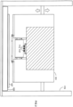
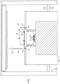
- Figures 1 to 3 represent a particularly preferred embodiment of an inkjet printing device according to the invention, in which the embodiments listed individually below are implemented as a combination.
- the means for mounting on the printing module 101 can comprise at least one device means for the releasable fixation 111.
- Corresponding counter-device means 111' are provided on the printing head 103.
- the means for the assembly can comprise at least one coupling means for a temporary fixation 113, wherein corresponding counter-coupling means 113' are provided on the print head 103.
- a temporary fixation of the print head 103 to the coupling means 113 of the print module 101 ensures that the print head 103, which has not yet been releasably fixed to the device means 111 by means of the fixing means 110, does not come loose from the (provisional) mounting position solely due to the force of gravity acting downwards on the print head 103.
- a print head 103 temporarily fixed in this way can only be released from the coupling means 111 by an external force.
- Such coupling means for the temporary fixation 113 can be used advantageously, for example, if a print head 103 has to be mounted in a position on the print module 101 that is difficult to reach, since it can be worked on easily with one hand.
- the device means for the releasable fixation 111 and the corresponding counter-device means 111' can be provided as a counterpart for a fixing means 110, which fixing means 110 can be designed as a screw device element or the coupling means for a temporary fixation 113 can be designed as an electrical connection element, in particular as a circuit board connector (socket or plug).
- the realized coupling means for a temporary fixation 113 is preferably directed downwards and the corresponding counter-coupling means 113' on the print head 103 is directed upwards.
- the assembly may comprise at least one fluidic connection 115 for the supply and/or discharge of ink, wherein the corresponding fluidic counter-connections 115' are provided on the print head 103.
- the at least one fluid connection 115 and the at least one coupling means for the temporary fixation 113 is held in a floating manner.
- Such an embodiment is particularly advantageous when a very precise positioning of the print head 103 in the assembly is to be made possible and achieved in one positioning step.
- the at least one fluid power connection 115 and the at least one coupling means for the temporary fixation 113 can be arranged such that a simultaneous coupling/uncoupling of the respective connections is provided.
- the at least one fluid connection 115 can have an automatic closure device 117 so that leakage of ink can be avoided when the fluid connection 115 is uncoupled. This is particularly advantageous because the storage device 115 is not soiled with ink when the print head 103 is replaced.
- the printing module 103 may comprise preset means for automatically aligning the print head 103, which may be adapted to press the print head 103 against two eccentrics arranged on two side flanks of an edge of the support frame 109 when the print head 103 is mounted in the assembly.
- the inkjet printer comprises the printing module 101 according to the invention in an embodiment in which the preferred elements outlined above can also be implemented and a positioning device 119 which is designed to be able to change the distance of the printing module 101 relative to a storage device 105 for a medium 107 to be printed on, wherein the positioning device 119 enables the printing module 101 to be adjusted between a working position and a repair position and, when printing on the medium 107 to be printed on, the printing module 101 can be positioned in the working position relative to the storage device 105 within a first distance interval, and when replacing the print head 103, the printing module 101 can be positioned in the repair position relative to the storage device 105 within a second distance interval.
- the minimum distance of the second distance interval in the repair position corresponds at least to the height of the print head 103.
- Figure 1 shows a particularly preferred embodiment of an inkjet printing device in which the printing module 101 is adjusted to the repair position in order to ensure that the print head 103 can be replaced.
- the printing module 101 is adjustably attached to the positioning device 119 via adjustment devices 121.
- the positioning device 119 rests, for example, on a base plate 120.
- the at least one coupling means for the temporary fixation 113 preferably provided on the printing module 101 is attached to a support device 125, which itself merges into a superstructure 127.
- At least some of the electronic and mechanical components required for the proper operation of the print head 103 are housed in the superstructure 127.
- the fluid connections 115 are integrally connected to the fluid lines 118 for the supply/discharge of the ink.
- Figure 2 shows the printing module 101, which is positioned in a working position in order to be able to print the medium 107 to be printed, which rests on the storage device 105.
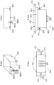
- the print head 103 is Figure 1 shown again enlarged.
- This print head 103 comprises a base element 137, which has at least one row of nozzles (not shown in the drawing), an ink chamber 135 with two upward-facing fluidic counter-connections 115', which enable the circulation of ink through the ink chamber 135, a superstructure 139 comprising electrical contacts for the at least one row of nozzles and laterally arranged heating mats for the uniform heating of the ink chamber 135 (not shown in the drawing).
- the print head 103 comprises counter-device means 111' for the releasable fixation on the print module 103, counter-coupling means 113' for the temporary fixation on the print module 103 and exchange means 141 arranged on the base element 138, which can be used as an aid for exchanging the print head 103.
- the fluid-technical counter-connections 115' have sealing rings 131, which Prevent ink leakage when connecting the fluidic mating connections 115' to the corresponding fluidic connections 115.
- Figure 4 shows the print head 103 from Figure 3 in top view.
- a change tool 141 which comprises counter-change means 143.
- Counter-change means 143 are brought into mutual engagement with change means 133 attached to the base element 135 of the print head 103.
- Such a tool can be used as an aid when replacing the print head 103.
- the change tool 141 comprises an integrated fixing means 110A.
- Figure 6 shows a perspective view of the changing tool 141.
- an integrated fixing means 110A can be understood as a combination connection of a screw with a screw nut 110B on the interchangeable tool 141, wherein the screw is introduced through a simple hole on the interchangeable tool 141 and is releasably fixed to the interchangeable tool 141 by a screw/screw nut connection.
- the printing module 101 can be provided with at least one device means for the releasable fixation 111 and the printing head 103 with corresponding counter-device means 111', such that the printing head 103 is releasably fixed with fixing means 110 in the assembly step according to the above-mentioned step e).
- the printing module 101 is additionally provided with at least one coupling means for the temporary fixation 113 and the printing head 103 with corresponding counter-coupling means 113', such that the assembly step according to the above-mentioned step e) takes place in two steps, in that in a first step the printing head 103 is temporarily fixed to the at least one coupling means for the temporary fixation 113 before the printing head 103 is releasably fixed to the device means for the releasable fixation 111 with fixing means 110 in the second step.
- the print head 103 is provided with a change means 133 and, in addition, a change tool 141, which comprises counter-change means 143 and an integrated fixing means 110A, is provided, wherein the removal and/or insertion of the print head 103 takes place according to the corresponding steps c), d) in such a way that the change means 133 of the print head 103 are brought into engagement with the corresponding counter-change means 143 and, before the removal and/or after the insertion of the print head 103, the change tool 141 with the integrated fixing means 110A is releasably fixed to auxiliary device means provided on the front of the support frame 109 and is removed after the execution of steps c) and/or d).
- the fixing means 110 can be inserted at the front and/or rear into the device means provided for the releasable fixation 111 and the corresponding counter-device means 111' with a fixing tool 112.
- Figure 7 shows a step of the replacement in which the printing module 103 is positioned in the repair position.
- the printing module 101 and its components in the figures are partly not shown to scale and/or enlarged and/or reduced.
Landscapes
- Ink Jet (AREA)
Claims (9)
- Module d'impression (101) comprenant un ensemble disposé sur le côté frontal pour monter une tête d'impression (103) dans une imprimante à jet d'encre, le module d'impression (101) étant espacé d'un dispositif de stockage (105) et l'ensemble comprenant un cadre support (109) ayant un orifice qui s'étend à travers le cadre support (109) et qui est prévue pour recevoir/ relâcher la tête d'impression (103), l'ensemble comprenant des moyens pour monter la tête d'impression (103), lesquels permettent d'insérer et d'enlever la même tête d'impression (101) sur le côté frontal dans une position de réparation du module d'impression (101) par rapport au dispositif de stockage (105), les moyens de montage comprenant au moins un moyen d'installation pour la fixation amovible (111) et, en plus, au moins un moyen de couplage (113) pour une fixation temporaire (113) de la tête d'impression (103), des contre-moyens d'installation (111') et de couplage (113') correspondants étant prévus sur la tête d'impression (103), caractérisé en ce que les moyens de couplage (113) sont conçus de telle manière qu'ils permettent d'insérer la tête d'impression sur le côté frontal à l'opposé de la direction de gravité et qu'une tête d'impression (103) fixée temporairement aux moyens de couplage (113) est fixée de telle manière que la tête d'impression qui n'a pas encore été fixée de manière amovible par des moyens de fixation (110) aux moyens d'installation (111), ne se détache pas d'une position de montage provisoire par la seule force de gravité agissant sur elle, mais elle ne peut être détachée des moyens de couplage (113) que par une force extérieure, ledit le moyen de couplage pour une fixation temporaire (113) étant orienté vers le bas et le contre-moyen de couplage correspondant (113') étant orienté sur la tête d'impression (103) vers le haut.
- Module d'impression (101) selon la revendication 1, caractérisé en ce que le moyen d'installation pour la fixation amovible (111) et le contre-moyen d'installation correspondant (111') sont chacun prévus comme contrepartie d'un moyen de fixation (110), quel moyen de fixation (110) peut être conçu comme un élément de dispositif à vis ou le moyen de couplage pour la fixation temporaire (113) est conçu comme un élément de raccord électrique, en particulier comme un connecteur de carte de circuit imprimé (connecteur mâle ou femelle).
- Module d'impression (101) selon la revendication 1 ou 2, caractérisé en ce que l'ensemble comprend au moins un raccord fluidique (115) pour l'alimentation et/ou la décharge d'encre, des contre-raccords fluidiques correspondants (115') étant prévus sur la tête d'impression (103) .
- Module d'impression (101) selon au moins l'une des revendications 1 à 3, caractérisé en ce que ledit au moins un raccord fluidique (115) et ledit au moins un moyen de couplage pour la fixation temporaire (113) sont maintenus de manière flottante.
- Module d'impression (101) selon la revendication 3 ou 4, caractérisé en ce que ledit au moins un raccord fluidique (115) et ledit au moins un moyen de couplage pour la fixation temporaire (113) sont disposés de telle manière qu'un couplage/découplage simultané des raccords respectifs est prévu.
- Module d'impression (101) selon au moins l'une des revendications 3 à 4, caractérisé en ce que ledit au moins un raccord fluidique (115) a un dispositif de fermeture automatique (117), de sorte qu'une fuite d'encre est évitable, lorsque ledit au moins un raccord fluidique (115) est découplée.
- Module d'impression (101) selon au moins l'une des revendications précédentes, caractérisé en ce que le module d'impression (103) comprend des moyens prédéfinis pour l'alignement automatique de la tête d'impression (103), ceux-ci étant adaptés de telle manière qu'ils pressent la tête d'impression (103) contre deux excentriques disposés sur deux flancs latéraux d'un bord du cadre support (109), lorsque la tête d'impression (103) est montée dans l'ensemble.
- Imprimante à jet d'encre comprenant un module d'impression (101) selon au moins l'une des revendications 1 à 7 et un dispositif de positionnement (119) qui est conçu pour pouvoir modifier la distance du module d'impression (101) par rapport à un dispositif de stockage (105) pour un support (107) à imprimer, caractérisé en ce que le module de positionnement (119) permet de déplacer le module d'impression (101) entre une position de travail et une position de réparation, et pendant l'impression sur le support à imprimer (107) le module d'impression (101) peut être positionné dans la position de travail par rapport au dispositif de stockage (105) dans un premier intervalle de distance, et lorsque la tête d'impression (103) est remplacée, le module d'impression (101) peut être positionné dans la position de réparation par rapport au dispositif de stockage (105) dans un deuxième intervalle de distance.
- Imprimante à jet d'encre selon la revendication 8, caractérisée en ce que, dans la position de réparation, la distance minimale du deuxième intervalle de distance correspond au moins à la hauteur de la tête d'impression (103).
Applications Claiming Priority (3)
| Application Number | Priority Date | Filing Date | Title |
|---|---|---|---|
| DE102014011882.7A DE102014011882A1 (de) | 2014-08-13 | 2014-08-13 | Druckmodul mit frontseitig auswechselbarem Druckkopf |
| ITBZ20140035 | 2014-09-16 | ||
| PCT/EP2015/001557 WO2016023620A1 (fr) | 2014-08-13 | 2015-07-29 | Module d'impression muni d'une tête d'impression remplaçable du côté avant |
Publications (3)
| Publication Number | Publication Date |
|---|---|
| EP3180195A1 EP3180195A1 (fr) | 2017-06-21 |
| EP3180195B1 EP3180195B1 (fr) | 2020-06-24 |
| EP3180195B2 true EP3180195B2 (fr) | 2024-05-08 |
Family
ID=53765181
Family Applications (1)
| Application Number | Title | Priority Date | Filing Date |
|---|---|---|---|
| EP15744881.2A Active EP3180195B2 (fr) | 2014-08-13 | 2015-07-29 | Module d'impression avec tête interchangeable a l'avant |
Country Status (4)
| Country | Link |
|---|---|
| US (1) | US10071548B2 (fr) |
| EP (1) | EP3180195B2 (fr) |
| ES (1) | ES2819510T5 (fr) |
| WO (1) | WO2016023620A1 (fr) |
Families Citing this family (5)
| Publication number | Priority date | Publication date | Assignee | Title |
|---|---|---|---|---|
| ES2640064B2 (es) * | 2016-04-29 | 2018-02-27 | Tecglass Sl | Carro, máquina y procedimiento de impresión digital sobre vidrio con módulos extraíbles |
| CN111070894B (zh) * | 2019-12-30 | 2025-06-27 | 厦门汉印股份有限公司 | 一种快拆式打印头模块及打印机 |
| CN119233896A (zh) | 2022-06-02 | 2024-12-31 | 马姆杰特科技有限公司 | 具有相对的枢转喷墨模块的打印单元 |
| KR102751725B1 (ko) * | 2022-06-30 | 2025-01-10 | 주식회사 고산테크 | 잉크젯 프린터용 헤드 어셈블리 및 이를 구비한 잉크젯 프린터 |
| JP2024141330A (ja) * | 2023-03-29 | 2024-10-10 | セイコーエプソン株式会社 | 印刷装置 |
Citations (1)
| Publication number | Priority date | Publication date | Assignee | Title |
|---|---|---|---|---|
| US20130314469A1 (en) † | 2010-07-22 | 2013-11-28 | Yuan Chang | Printhead mounting and adjusting mechanism for inkjet printer |
Family Cites Families (13)
| Publication number | Priority date | Publication date | Assignee | Title |
|---|---|---|---|---|
| DE69220273T2 (de) | 1991-03-28 | 1998-01-22 | Canon Kk | Bogenfördergerät für eine Aufzeichnungsvorrichtung |
| JP3800995B2 (ja) * | 2001-06-26 | 2006-07-26 | ブラザー工業株式会社 | インクジェット記録装置 |
| US6471335B1 (en) * | 2001-08-06 | 2002-10-29 | Creo Inc. | Method for mutual spatial registration of inkjet cartridges |
| DE10164527A1 (de) | 2001-12-15 | 2003-07-10 | Francotyp Postalia Ag | Anordnung zum Schutz eines Druckmoduls in einem Postverarbeitungsgerät |
| JP4415663B2 (ja) | 2003-12-12 | 2010-02-17 | ソニー株式会社 | 液体吐出装置 |
| GB0502440D0 (en) * | 2005-02-07 | 2005-03-16 | Xaar Technology Ltd | Printing machines |
| AT501432B1 (de) | 2005-02-08 | 2008-04-15 | Durst Phototech Digital Tech | Tintenstrahldruckvorrichtung und verfahren zum drucken von mehrfarbigen bildern |
| US7533976B2 (en) | 2005-04-27 | 2009-05-19 | Hewlett-Packard Development Company, L.P. | Sealing component defining first, second, and third seals |
| JP5194639B2 (ja) * | 2007-08-22 | 2013-05-08 | セイコーエプソン株式会社 | 液体噴射ヘッド用のメンテナンス装置及び液体噴射装置 |
| DE102010037829A1 (de) | 2010-09-28 | 2012-03-29 | OCé PRINTING SYSTEMS GMBH | Druckwerk für ein Tintendruckgerät |
| JP2012111098A (ja) | 2010-11-24 | 2012-06-14 | Seiko Epson Corp | 液体噴射ヘッドユニット、および、その製造方法 |
| JP5928674B2 (ja) | 2011-01-14 | 2016-06-01 | セイコーエプソン株式会社 | 液体噴射ヘッドユニット及び液体噴射装置 |
| JP6119173B2 (ja) | 2012-05-02 | 2017-04-26 | セイコーエプソン株式会社 | 液体噴射ヘッドモジュール及び液体噴射装置 |
-
2015
- 2015-07-29 US US15/502,529 patent/US10071548B2/en active Active
- 2015-07-29 EP EP15744881.2A patent/EP3180195B2/fr active Active
- 2015-07-29 WO PCT/EP2015/001557 patent/WO2016023620A1/fr not_active Ceased
- 2015-07-29 ES ES15744881T patent/ES2819510T5/es active Active
Patent Citations (1)
| Publication number | Priority date | Publication date | Assignee | Title |
|---|---|---|---|---|
| US20130314469A1 (en) † | 2010-07-22 | 2013-11-28 | Yuan Chang | Printhead mounting and adjusting mechanism for inkjet printer |
Also Published As
| Publication number | Publication date |
|---|---|
| ES2819510T3 (es) | 2021-04-16 |
| WO2016023620A1 (fr) | 2016-02-18 |
| EP3180195B1 (fr) | 2020-06-24 |
| US20170232769A1 (en) | 2017-08-17 |
| WO2016023620A8 (fr) | 2017-05-11 |
| US10071548B2 (en) | 2018-09-11 |
| EP3180195A1 (fr) | 2017-06-21 |
| ES2819510T5 (en) | 2024-12-18 |
Similar Documents
| Publication | Publication Date | Title |
|---|---|---|
| EP3180195B2 (fr) | Module d'impression avec tête interchangeable a l'avant | |
| DE68918074T2 (de) | Tintenstrahlaufzeichnungskopf und Tintenstrahlaufzeichnungsgerät. | |
| BE1017612A5 (de) | Inkjet-druckeinrichtung. | |
| EP3463903A1 (fr) | Tête de nettoyage et dispositif et procédé de nettoyage de têtes d'impression | |
| DE10331275A1 (de) | Befestigungs- oder Einbauvorrichtung für ein fahrzeugseitiges Teil | |
| EP2346689B1 (fr) | Agencement de tables d'impression | |
| EP3450182A1 (fr) | Imprimante destinée à l'impression direct de récipients | |
| EP0086954B1 (fr) | Outil d'extraction d'un tiroir électronique de son support | |
| WO2018041705A1 (fr) | Dispositif et procédé pour l'assemblage d'un cabochon avec un boîtier d'un dispositif d'éclairage d'un véhicule automobile | |
| DE102014011882A1 (de) | Druckmodul mit frontseitig auswechselbarem Druckkopf | |
| AT407060B (de) | Vorrichtung zum wechseln der nadelbretter einer nadelmaschine | |
| DE102014110278A1 (de) | Halterahmen für Steckverbindermodule und/oder Steckverbinder | |
| DE102010038145A1 (de) | Kühleinrichtung für ein Rändelwerkzeug | |
| DE69937096T2 (de) | Mechanismus zum installieren und halten eines durckkopfs | |
| EP3996927B1 (fr) | Imprimante pour imprimer des supports d'impression de type panneaux, dispositif d'assainissement pour l'imprimante et procédé d'entretien de l'imprimante | |
| DE102019131972B4 (de) | Befestigungsvorrichtung für eine elektronische Baugruppe | |
| DE202012000263U1 (de) | Drucksystem | |
| DE102013217952B3 (de) | Vorrichtung zur Zuführung eines Heißgasstroms | |
| DE102020128910B4 (de) | Haltevorrichtung zur Befestigung einer elektrischen Baugruppe an einem Druckkopf und eine entsprechende Druckkopf-Anordnung | |
| DE102019123099B3 (de) | Vorrichtung und Verfahren zum Herstellen von Schaltmodulen mit einem Gehäuse und zumindest einer darin eingeführten Elektronikkomponente | |
| DE69707192T2 (de) | Werkzeuglose Druckkopfhalterung | |
| EP3733420B1 (fr) | Module de tête d'impression et système d'impression d'essai | |
| EP3490805B1 (fr) | Dispositif et procédé d'alignement de têtes d'impression | |
| EP3296114A1 (fr) | Imprimante pourvue de système d'extraction pour un module d'impression | |
| EP2638591A1 (fr) | Circuit réfrigérant pour un système de cellules de combustible et procédé pour l'accouplement fluidique d'un module d'échangeur d'ions doté d'un composant d'un circuit réfrigérant |
Legal Events
| Date | Code | Title | Description |
|---|---|---|---|
| STAA | Information on the status of an ep patent application or granted ep patent |
Free format text: STATUS: THE INTERNATIONAL PUBLICATION HAS BEEN MADE |
|
| PUAI | Public reference made under article 153(3) epc to a published international application that has entered the european phase |
Free format text: ORIGINAL CODE: 0009012 |
|
| STAA | Information on the status of an ep patent application or granted ep patent |
Free format text: STATUS: REQUEST FOR EXAMINATION WAS MADE |
|
| 17P | Request for examination filed |
Effective date: 20170313 |
|
| AK | Designated contracting states |
Kind code of ref document: A1 Designated state(s): AL AT BE BG CH CY CZ DE DK EE ES FI FR GB GR HR HU IE IS IT LI LT LU LV MC MK MT NL NO PL PT RO RS SE SI SK SM TR |
|
| AX | Request for extension of the european patent |
Extension state: BA ME |
|
| DAV | Request for validation of the european patent (deleted) | ||
| DAX | Request for extension of the european patent (deleted) | ||
| RAP1 | Party data changed (applicant data changed or rights of an application transferred) |
Owner name: DURST PHOTOTECHNIK AG |
|
| GRAP | Despatch of communication of intention to grant a patent |
Free format text: ORIGINAL CODE: EPIDOSNIGR1 |
|
| STAA | Information on the status of an ep patent application or granted ep patent |
Free format text: STATUS: GRANT OF PATENT IS INTENDED |
|
| INTG | Intention to grant announced |
Effective date: 20200220 |
|
| GRAS | Grant fee paid |
Free format text: ORIGINAL CODE: EPIDOSNIGR3 |
|
| GRAA | (expected) grant |
Free format text: ORIGINAL CODE: 0009210 |
|
| STAA | Information on the status of an ep patent application or granted ep patent |
Free format text: STATUS: THE PATENT HAS BEEN GRANTED |
|
| AK | Designated contracting states |
Kind code of ref document: B1 Designated state(s): AL AT BE BG CH CY CZ DE DK EE ES FI FR GB GR HR HU IE IS IT LI LT LU LV MC MK MT NL NO PL PT RO RS SE SI SK SM TR |
|
| REG | Reference to a national code |
Ref country code: GB Ref legal event code: FG4D Free format text: NOT ENGLISH |
|
| REG | Reference to a national code |
Ref country code: CH Ref legal event code: EP |
|
| REG | Reference to a national code |
Ref country code: AT Ref legal event code: REF Ref document number: 1283498 Country of ref document: AT Kind code of ref document: T Effective date: 20200715 |
|
| REG | Reference to a national code |
Ref country code: DE Ref legal event code: R096 Ref document number: 502015012871 Country of ref document: DE |
|
| REG | Reference to a national code |
Ref country code: IE Ref legal event code: FG4D Free format text: LANGUAGE OF EP DOCUMENT: GERMAN |
|
| PG25 | Lapsed in a contracting state [announced via postgrant information from national office to epo] |
Ref country code: LT Free format text: LAPSE BECAUSE OF FAILURE TO SUBMIT A TRANSLATION OF THE DESCRIPTION OR TO PAY THE FEE WITHIN THE PRESCRIBED TIME-LIMIT Effective date: 20200624 Ref country code: FI Free format text: LAPSE BECAUSE OF FAILURE TO SUBMIT A TRANSLATION OF THE DESCRIPTION OR TO PAY THE FEE WITHIN THE PRESCRIBED TIME-LIMIT Effective date: 20200624 Ref country code: GR Free format text: LAPSE BECAUSE OF FAILURE TO SUBMIT A TRANSLATION OF THE DESCRIPTION OR TO PAY THE FEE WITHIN THE PRESCRIBED TIME-LIMIT Effective date: 20200925 Ref country code: NO Free format text: LAPSE BECAUSE OF FAILURE TO SUBMIT A TRANSLATION OF THE DESCRIPTION OR TO PAY THE FEE WITHIN THE PRESCRIBED TIME-LIMIT Effective date: 20200924 Ref country code: SE Free format text: LAPSE BECAUSE OF FAILURE TO SUBMIT A TRANSLATION OF THE DESCRIPTION OR TO PAY THE FEE WITHIN THE PRESCRIBED TIME-LIMIT Effective date: 20200624 |
|
| REG | Reference to a national code |
Ref country code: LT Ref legal event code: MG4D |
|
| PG25 | Lapsed in a contracting state [announced via postgrant information from national office to epo] |
Ref country code: BG Free format text: LAPSE BECAUSE OF FAILURE TO SUBMIT A TRANSLATION OF THE DESCRIPTION OR TO PAY THE FEE WITHIN THE PRESCRIBED TIME-LIMIT Effective date: 20200924 Ref country code: LV Free format text: LAPSE BECAUSE OF FAILURE TO SUBMIT A TRANSLATION OF THE DESCRIPTION OR TO PAY THE FEE WITHIN THE PRESCRIBED TIME-LIMIT Effective date: 20200624 Ref country code: RS Free format text: LAPSE BECAUSE OF FAILURE TO SUBMIT A TRANSLATION OF THE DESCRIPTION OR TO PAY THE FEE WITHIN THE PRESCRIBED TIME-LIMIT Effective date: 20200624 Ref country code: HR Free format text: LAPSE BECAUSE OF FAILURE TO SUBMIT A TRANSLATION OF THE DESCRIPTION OR TO PAY THE FEE WITHIN THE PRESCRIBED TIME-LIMIT Effective date: 20200624 |
|
| REG | Reference to a national code |
Ref country code: NL Ref legal event code: MP Effective date: 20200624 |
|
| PG25 | Lapsed in a contracting state [announced via postgrant information from national office to epo] |
Ref country code: AL Free format text: LAPSE BECAUSE OF FAILURE TO SUBMIT A TRANSLATION OF THE DESCRIPTION OR TO PAY THE FEE WITHIN THE PRESCRIBED TIME-LIMIT Effective date: 20200624 Ref country code: NL Free format text: LAPSE BECAUSE OF FAILURE TO SUBMIT A TRANSLATION OF THE DESCRIPTION OR TO PAY THE FEE WITHIN THE PRESCRIBED TIME-LIMIT Effective date: 20200624 |
|
| PG25 | Lapsed in a contracting state [announced via postgrant information from national office to epo] |
Ref country code: SM Free format text: LAPSE BECAUSE OF FAILURE TO SUBMIT A TRANSLATION OF THE DESCRIPTION OR TO PAY THE FEE WITHIN THE PRESCRIBED TIME-LIMIT Effective date: 20200624 Ref country code: EE Free format text: LAPSE BECAUSE OF FAILURE TO SUBMIT A TRANSLATION OF THE DESCRIPTION OR TO PAY THE FEE WITHIN THE PRESCRIBED TIME-LIMIT Effective date: 20200624 Ref country code: RO Free format text: LAPSE BECAUSE OF FAILURE TO SUBMIT A TRANSLATION OF THE DESCRIPTION OR TO PAY THE FEE WITHIN THE PRESCRIBED TIME-LIMIT Effective date: 20200624 Ref country code: CZ Free format text: LAPSE BECAUSE OF FAILURE TO SUBMIT A TRANSLATION OF THE DESCRIPTION OR TO PAY THE FEE WITHIN THE PRESCRIBED TIME-LIMIT Effective date: 20200624 Ref country code: PT Free format text: LAPSE BECAUSE OF FAILURE TO SUBMIT A TRANSLATION OF THE DESCRIPTION OR TO PAY THE FEE WITHIN THE PRESCRIBED TIME-LIMIT Effective date: 20201026 |
|
| PG25 | Lapsed in a contracting state [announced via postgrant information from national office to epo] |
Ref country code: SK Free format text: LAPSE BECAUSE OF FAILURE TO SUBMIT A TRANSLATION OF THE DESCRIPTION OR TO PAY THE FEE WITHIN THE PRESCRIBED TIME-LIMIT Effective date: 20200624 Ref country code: PL Free format text: LAPSE BECAUSE OF FAILURE TO SUBMIT A TRANSLATION OF THE DESCRIPTION OR TO PAY THE FEE WITHIN THE PRESCRIBED TIME-LIMIT Effective date: 20200624 Ref country code: IS Free format text: LAPSE BECAUSE OF FAILURE TO SUBMIT A TRANSLATION OF THE DESCRIPTION OR TO PAY THE FEE WITHIN THE PRESCRIBED TIME-LIMIT Effective date: 20201024 |
|
| REG | Reference to a national code |
Ref country code: CH Ref legal event code: PL |
|
| REG | Reference to a national code |
Ref country code: DE Ref legal event code: R026 Ref document number: 502015012871 Country of ref document: DE |
|
| PLBI | Opposition filed |
Free format text: ORIGINAL CODE: 0009260 |
|
| PG25 | Lapsed in a contracting state [announced via postgrant information from national office to epo] |
Ref country code: MC Free format text: LAPSE BECAUSE OF FAILURE TO SUBMIT A TRANSLATION OF THE DESCRIPTION OR TO PAY THE FEE WITHIN THE PRESCRIBED TIME-LIMIT Effective date: 20200624 |
|
| PLAX | Notice of opposition and request to file observation + time limit sent |
Free format text: ORIGINAL CODE: EPIDOSNOBS2 |
|
| REG | Reference to a national code |
Ref country code: ES Ref legal event code: FG2A Ref document number: 2819510 Country of ref document: ES Kind code of ref document: T3 Effective date: 20210416 |
|
| 26 | Opposition filed |
Opponent name: DOMINO UK LIMITED Effective date: 20210323 |
|
| REG | Reference to a national code |
Ref country code: BE Ref legal event code: MM Effective date: 20200731 |
|
| PG25 | Lapsed in a contracting state [announced via postgrant information from national office to epo] |
Ref country code: CH Free format text: LAPSE BECAUSE OF NON-PAYMENT OF DUE FEES Effective date: 20200731 Ref country code: DK Free format text: LAPSE BECAUSE OF FAILURE TO SUBMIT A TRANSLATION OF THE DESCRIPTION OR TO PAY THE FEE WITHIN THE PRESCRIBED TIME-LIMIT Effective date: 20200624 Ref country code: LI Free format text: LAPSE BECAUSE OF NON-PAYMENT OF DUE FEES Effective date: 20200731 Ref country code: LU Free format text: LAPSE BECAUSE OF NON-PAYMENT OF DUE FEES Effective date: 20200729 |
|
| PG25 | Lapsed in a contracting state [announced via postgrant information from national office to epo] |
Ref country code: BE Free format text: LAPSE BECAUSE OF NON-PAYMENT OF DUE FEES Effective date: 20200731 |
|
| PLBB | Reply of patent proprietor to notice(s) of opposition received |
Free format text: ORIGINAL CODE: EPIDOSNOBS3 |
|
| PG25 | Lapsed in a contracting state [announced via postgrant information from national office to epo] |
Ref country code: IE Free format text: LAPSE BECAUSE OF NON-PAYMENT OF DUE FEES Effective date: 20200729 Ref country code: SI Free format text: LAPSE BECAUSE OF FAILURE TO SUBMIT A TRANSLATION OF THE DESCRIPTION OR TO PAY THE FEE WITHIN THE PRESCRIBED TIME-LIMIT Effective date: 20200624 |
|
| RAP4 | Party data changed (patent owner data changed or rights of a patent transferred) |
Owner name: DURST GROUP AG |
|
| PG25 | Lapsed in a contracting state [announced via postgrant information from national office to epo] |
Ref country code: TR Free format text: LAPSE BECAUSE OF FAILURE TO SUBMIT A TRANSLATION OF THE DESCRIPTION OR TO PAY THE FEE WITHIN THE PRESCRIBED TIME-LIMIT Effective date: 20200624 Ref country code: MT Free format text: LAPSE BECAUSE OF FAILURE TO SUBMIT A TRANSLATION OF THE DESCRIPTION OR TO PAY THE FEE WITHIN THE PRESCRIBED TIME-LIMIT Effective date: 20200624 Ref country code: CY Free format text: LAPSE BECAUSE OF FAILURE TO SUBMIT A TRANSLATION OF THE DESCRIPTION OR TO PAY THE FEE WITHIN THE PRESCRIBED TIME-LIMIT Effective date: 20200624 |
|
| PG25 | Lapsed in a contracting state [announced via postgrant information from national office to epo] |
Ref country code: MK Free format text: LAPSE BECAUSE OF FAILURE TO SUBMIT A TRANSLATION OF THE DESCRIPTION OR TO PAY THE FEE WITHIN THE PRESCRIBED TIME-LIMIT Effective date: 20200624 |
|
| PUAH | Patent maintained in amended form |
Free format text: ORIGINAL CODE: 0009272 |
|
| STAA | Information on the status of an ep patent application or granted ep patent |
Free format text: STATUS: PATENT MAINTAINED AS AMENDED |
|
| 27A | Patent maintained in amended form |
Effective date: 20240508 |
|
| AK | Designated contracting states |
Kind code of ref document: B2 Designated state(s): AL AT BE BG CH CY CZ DE DK EE ES FI FR GB GR HR HU IE IS IT LI LT LU LV MC MK MT NL NO PL PT RO RS SE SI SK SM TR |
|
| REG | Reference to a national code |
Ref country code: DE Ref legal event code: R102 Ref document number: 502015012871 Country of ref document: DE |
|
| REG | Reference to a national code |
Ref country code: ES Ref legal event code: DC2A Ref document number: 2819510 Country of ref document: ES Kind code of ref document: T5 Effective date: 20241218 |
|
| PGFP | Annual fee paid to national office [announced via postgrant information from national office to epo] |
Ref country code: ES Payment date: 20250819 Year of fee payment: 11 |
|
| PGFP | Annual fee paid to national office [announced via postgrant information from national office to epo] |
Ref country code: DE Payment date: 20250722 Year of fee payment: 11 |
|
| PGFP | Annual fee paid to national office [announced via postgrant information from national office to epo] |
Ref country code: IT Payment date: 20250731 Year of fee payment: 11 |
|
| PGFP | Annual fee paid to national office [announced via postgrant information from national office to epo] |
Ref country code: GB Payment date: 20250724 Year of fee payment: 11 |
|
| PGFP | Annual fee paid to national office [announced via postgrant information from national office to epo] |
Ref country code: AT Payment date: 20250721 Year of fee payment: 11 Ref country code: FR Payment date: 20250723 Year of fee payment: 11 |