EP3180201B1 - Outil a main pour changer des pneus - Google Patents
Outil a main pour changer des pneus Download PDFInfo
- Publication number
- EP3180201B1 EP3180201B1 EP15749857.7A EP15749857A EP3180201B1 EP 3180201 B1 EP3180201 B1 EP 3180201B1 EP 15749857 A EP15749857 A EP 15749857A EP 3180201 B1 EP3180201 B1 EP 3180201B1
- Authority
- EP
- European Patent Office
- Prior art keywords
- engagement portion
- rim
- tyre
- flange
- bead
- Prior art date
- Legal status (The legal status is an assumption and is not a legal conclusion. Google has not performed a legal analysis and makes no representation as to the accuracy of the status listed.)
- Active
Links
Images


Classifications
-
- B—PERFORMING OPERATIONS; TRANSPORTING
- B60—VEHICLES IN GENERAL
- B60C—VEHICLE TYRES; TYRE INFLATION; TYRE CHANGING; CONNECTING VALVES TO INFLATABLE ELASTIC BODIES IN GENERAL; DEVICES OR ARRANGEMENTS RELATED TO TYRES
- B60C25/00—Apparatus or tools adapted for mounting, removing or inspecting tyres
- B60C25/01—Apparatus or tools adapted for mounting, removing or inspecting tyres for removing tyres from or mounting tyres on wheels
- B60C25/02—Tyre levers or the like, e.g. hand-held
-
- B—PERFORMING OPERATIONS; TRANSPORTING
- B25—HAND TOOLS; PORTABLE POWER-DRIVEN TOOLS; MANIPULATORS
- B25D—PERCUSSIVE TOOLS
- B25D1/00—Hand hammers; Hammer heads of special shape or materials
-
- B—PERFORMING OPERATIONS; TRANSPORTING
- B25—HAND TOOLS; PORTABLE POWER-DRIVEN TOOLS; MANIPULATORS
- B25D—PERCUSSIVE TOOLS
- B25D2250/00—General details of portable percussive tools; Components used in portable percussive tools
- B25D2250/005—Adjustable tool components; Adjustable parameters
-
- B—PERFORMING OPERATIONS; TRANSPORTING
- B60—VEHICLES IN GENERAL
- B60C—VEHICLE TYRES; TYRE INFLATION; TYRE CHANGING; CONNECTING VALVES TO INFLATABLE ELASTIC BODIES IN GENERAL; DEVICES OR ARRANGEMENTS RELATED TO TYRES
- B60C25/00—Apparatus or tools adapted for mounting, removing or inspecting tyres
- B60C25/01—Apparatus or tools adapted for mounting, removing or inspecting tyres for removing tyres from or mounting tyres on wheels
Definitions
- the present invention relates generally to the field of bicycle tools and more particularly, to a tool for facilitating the removal and installation of tyres mounted to a rim, such as, for example, bicycle tyres.
- a typical modern wheel such as a bicycle wheel, has a metal hub, wire tension spokes and a metal or carbon fibre rim which holds a pneumatic rubber tyre, usually including an inner tube.
- the rim is commonly a metal extrusion that is butted into itself to form a hoop, though may also be a structure of carbon fibre composite.
- Some wheels use both an aerodynamic carbon hoop bonded to an aluminium rim on which to mount conventional bicycle tyres.
- Rims designed for use with rim brakes comprise opposing flanges so as to provide a smooth parallel braking surface.
- Wheel rims also come in a variety of diameter and widths to provide optimum performance for different uses. For example, high performance road racing rims are relatively narrow, e.g. 18 mm, whereas wider touring or durable off-road tires usually require rims that are 24 mm wide or more.
- tyre levers are utilised to pry a bead section of the tyre away from the rim and then lift (lever) this bead section over and out of the rim.
- the other end of the tyre lever is then hooked around a spoke to keep the tyre bead free from the rim and allowing a second tyre lever to lift another bead section over and away from the rim.
- the bead of a tyre usually includes a wire or aramid fibres, which makes the bead relatively rigid in structure. Consequently, a considerable force has to be generated to stretch the bead over the rim section. The required stretch is also increased by the thickness of the tyre lever, which must also be overcome when lifting the bead section over the rim.
- Figure 1 illustrates a typical bicycle wheel 10 having a rim 12, spokes 14 and a tyre 16 with an inflatable tube (not shown) inside the tyre.
- Figure 2 (a) illustrates a cross section of the wheel 10 shown in Figure 1 with the tyre 16 and inner tube 18 installed on the rim 12. The tyre bead 20 is engaged with a groove running around the inner wall of the rim flanges 24 so as to secure the tyre 16 to the rim 12.
- Figure 2 (b) illustrates a cross section of another "clincher"-type wheel where part of the tyre bead 20 is moved out of the rim 12.
- the bead 20 of a tyre 16 is fitted to the rim 12 by utilising a simple lever 30 that is "wedged" between the inside of the rim flange 24 and the tyre bead 20.
- a simple lever 30 that is "wedged" between the inside of the rim flange 24 and the tyre bead 20.
- the contact point between the tyre lever 30 and the flange 24 forms a fulcrum for the tyre lever 30, allowing sufficient force to be generated at the tyre lever end to stretch and lift the bead section 20 over the flange 24.
- document FR543526 discloses, inter alia, an improved lever having a handle portion, a lever portion (10), a ""fixed” rim contact point (9) on one end of the lever portion (10) and a lip (11) for engaging the tyre bead located outside the rim. During use, this tool is provided over the tyre.
- This document provides all the features of the preamble of claim 1.
- Document FR506081 discloses a tyre lever ('A') comprising a handle portion and a lever portion.
- the lever portion has a first contact point (hook 'C') that is adapted to hookingly engage a flange of the rim and a second contact point (projecting ledge 'B') that is adapted to engage an overlapping tyre bead.
- this tool is provided under the rim.
- Document GB191134 discloses another "over the tyre" tyre lever.
- the tyre lever has, inter alia, an adjustable handle portion (flat bar 'f') and a projection 'g' that is adapted to engage with a tyre bead, as well as, a substantially semi-circular member 'a' having a bifurcation 'b', 'c' at the outer end.
- the bifurcation 'b', 'c' is placed on one edge of the wheel rim, so as to form a "fixed" pivot point, and projection 'g' is forced against one edge of the outer cover of a tyre.
- projection 'g' raises the tyre bead either into or out of the rim.
- Preferred embodiments of the invention seek to overcome one or more of the above disadvantages of the prior art.
- a tool for installing and removing a tyre having a bead comprising a substantially elongated body member having a longitudinal axis, the body member further comprising:
- the cross sectional profile of common tyre levers has to be relatively thin to allow the lever to be wedged between the rim flange and the bead and to minimise the additional stretch required to lift the bead over the rim flange. Consequently, the relatively thin cross sectional profile of common tyre levers greatly compromises the structural strength and provides an increased risk of breaking the lever during use.
- the tool of the present invention provides the advantage that any cross sectional profile may be used, so as to provide sufficient structural strength minimising the risk of breaking (or bending) the lever during use.
- the tool can be applied to a range of different rim widths without the need for adjustment of the tool, i.e. the fulcrum is simple shifted up or down the angled first planar contact surface.
- the second engagement portion may comprise a lip portion projecting towards said first engagement member.
- the lip portion may further comprise a second planar contact surface arranged substantially perpendicular with respect to the outer surface of the second flange when contacting the outer surface of the flange during use.
- the bridge portion may be of arcuate shape.
- the first engagement portion may further comprise at least one interchangeable contact surface member, having a third planar contact surface, and which is adapted to be removably secured to said first engagement portion.
- a relatively soft contact surface member may be used for a carbon-fibre rim, wherein a harder contact surface member may be more advantageous when used with a metal or aluminium rim.
- the material of the interchangeable contact surface member may be selected with regards to its hardness in respect to the rim and/or its contact properties when engaging with the rim.
- the third planar contact surface may be arranged at said predetermined angle with respect to said longitudinal axis when said at least one interchangeable contact surface member is secured to said first engagement portion.
- the at least one interchangeable contact surface member further may comprise a mounting portion adapted to demountably engage with said first engagement portion.
- the mounting portion may comprise any one of a clip mechanism and/or a sliding guide mechanism adapted to attachingly engage with a respective clip retaining recess provided at said first engagement portion.
- the mounting portion may comprise an adhering member adapted to attachingly engage with a respective adhering member attached to said first planar contact surface of said first engagement portion.
- the at least one interchangeable contact surface member may be made from a material that is structurally softer than the material of the engaged first and second rim flanges of a wheel.
- the handle portion, said first engagement portion, said second engagement portion and said bridge portion are integral parts of said body member.
- the tool of the present invention may further comprise at least one adjustment mechanism adapted to selectively move said first engagement portion and/or said second engagement portion, so as to increase or decrease said predetermined distance between said first engagement portion and said second engagement portion.
- the at least one adjustment mechanism may be operably coupled within said bridge portion and/or between said first engagement portion and said handle portion.
- the adjustment mechanism comprises a selectively lockable screw-type mechanism.
- the adjustment mechanism comprises a selectively lockable pivot joint.
- the adjustment mechanism comprises a ratchet-type mechanism.
- the tool of the present invention may further comprise a third engagement portion that is arranged at a second end of said handle portion, and which is adapted to cooperatively engage with a bead portion of a tyre, located within a rim of the wheel, and the adjacent flange portion of the rim, so as to lever the bead portion up and over the flange portion and move the bead portion out of the rim during use.
- a third engagement portion that is arranged at a second end of said handle portion, and which is adapted to cooperatively engage with a bead portion of a tyre, located within a rim of the wheel, and the adjacent flange portion of the rim, so as to lever the bead portion up and over the flange portion and move the bead portion out of the rim during use.
- the third engagement portion may comprise a first recess adapted to matingly engage with the flange portion of the rim so as to form a fulcrum, and a second recess adapted to hookingly engage with the bead portion of the tyre.
- said first recess and said second recess are located on opposite corners of said second end of said handle portion forming a lever between said first and second recess when said first recess is engaged with the flange portion of the rim.
- said first recess and said second recess are substantially semi-circular notches.
- the third engagement portion may comprise an inclined surface adapted to move the bead portion of a tyre up and over the flange portion when moving said inclined surface towards a predetermined direction along the flange portion of the rim.
- the inclined surface may be provided by two opposing grooves on opposite surfaces of said third engagement portion so as to form a wedge with a double-concave cross-section. Even more preferably, the predetermined direction may be towards the tapered end of said wedge.
- said substantially elongated body member may be made of a rigid material.
- said rigid material may be a plastic material.
- a first embodiment of the tool 100 of the present invention is made from a single piece of a rigid material.
- the tool 100 is made from plastic.
- any suitably rigid material e.g. metal, or composite material may be used.
- the tool 100 of the first embodiment comprises a handle portion 102 having a first end 104 and a second end 106.
- the first end 104 seamlessly merges into a first engagement portion 108 and bridge portion 110.
- the other end of the bridge portion 110 comprises a second engagement portion 112 located opposite and spaced apart from the first engagement portion 108.
- the recess area 114 defined by the arcuate bridge portion 110 is dimensioned to accommodate the profile of a wheel 10 and installed tyre 16 during use.
- the first engagement portion 108 defines a planar surface 116 whose planar orientation is inclined with respect to the longitudinal axis 118 of the tool 100.
- the angle ⁇ between the planar surface 116 and the longitudinal axis is an acute angle suitable to be operably placed onto the top of the rim flange 24, so as to provide a fulcrum for the tool 100.
- the angle ⁇ is within the range of 20° to 60°. Even more preferably, the angle ⁇ is 39°.
- the second engagement portion 112 comprises a lip portion 120 projecting towards the planar surface 116 of the first engagement portion 108.
- first and second engagement portion 108, 112 are arranged in line with the circumference of the arcuate bridge portion 110.
- bridge portion may be of any shape (e.g. rectangular) suitable to accommodate a wheel 10 and installed tyre 16 during use.
- the lip portion 120 further comprises a substantially planar contact surface 122 adapted to engage the bead section 20 from below during use.
- the planar contact surface 122 is arranged substantially perpendicular to the outer surface of the flange 24 when in use (i.e.
- the lip portion 120 may comprise a slightly hooked end so as to provide a more secure grip on the bead section 20 during the engagement.
- first and second engagement portion 108, 112 are generally spaced apart in a direction along the longitudinal axis 118 by a distance suitable for a predetermined range of rim widths.
- the closest distance between the lip portion 120 and the planar surface 116 may be 15 mm. Since the planar surface 116 is orientated at an angle ⁇ with respect to the longitudinal axis 118 of the tool 100, the tool 100 can be used on a specific range of rim widths. Alternatively, a tool 100 having a different distance between the lip portion 120 and the planar surface 116 may be provided to accommodate a different range of rim widths and tyre sizes.
- the bead section 20 can slide over the edge of the flange 24 inside the rim 12. There is no need to stretch the bead 20 any further than up to the edge of the flange 24, therefore reducing the force applied to the handle portion 102 to an absolute minimum necessary to lift the bead up and over the flange 24 into the rim 12. During this process, there is no contact between the tool 100 and the inner tube 18, eliminating the risk of damaging the inner tube 18 when installing the tyre 16 onto the rim 12.
- a second embodiment of the tool of the present invention further comprises an adjustment mechanism 200, 300, 400, 600 that is adapted to increase or decrease the distance between the first engagement portion 108 and the second engagement portion 112, therefore, providing a single tool 100 that can accommodate an increased range of rim widths and tyre sizes.
- the adjustment mechanism 200 a screw-type spacer mechanism
- the adjustment mechanism 200 is incorporated into the bridge portion 110 of the tool 100.
- the dial 202 of the screw-type spacer mechanism 200 is linearly away or towards the first engagement portion 108, consequently increasing or decreasing the distance between the first engagement portion 108 and the second engagement portion 112.
- the adjustment mechanism 200 further comprises a lock (not shown) adapted to lock the adjustment mechanism 200 in place once a desired width is set.
- the adjustment mechanism 300 may be installed between the first engagement portion 108 and the handle portion 102 and/or bridge portion 110, allowing, for example, the planar surface 116 to be moved toward or away from the handle- / bridge portion 102, 110, thus increasing or decreasing the distance between the first engagement portion 108 and the second engagement portion 112.
- the adjustment mechanism 400 may be a lockable pivot joint 402 pivotably coupling a first and second part of the bridge portion 110.
- a lockable pivot joint 402 pivotably coupling a first and second part of the bridge portion 110.
- at least one of the two halves of the bridge portion 110 is/are rotated about the pivot joint 402 and locked into place once a desired distance between the first engagement portion 108 and the second engagement portion 112 is reached.
- the adjustment mechanism 600 may be a ratchet-type mechanism 602 coupling a first part 110A and second part 110B of the bridge portion 110.
- a spring-loaded actuator 604 may lock the "sawtoothed" first part 110A of the bridge portion 110 in a desired position, wherein upon actuation of the actuator 604, the first part 110A of the bridge portion 110 may be moved so as to increase or decrease the distance between the first engagement portion 108 and the second engagement portion 112.
- the tool 100 of the present invention further comprises a third engagement portion 500 suitable for moving a bead section 20 out of engagement with a rim 12.
- the third engagement portion 500 is located at a second end of the handle portion 102, comprising a first recess 502, adapted to matingly engage with the top edge of a flange 24, and a second recess 504 spaced apart from the first recess 502 in a direction perpendicular to the longitudinal axis 118 and adapted to hookingly engage with a bead 20 of a tyre 16.
- the distance between the first and second recess 502, 504 is part of a lever formed by the tool 100 and the fulcrum on the first recess 502 to move the bead 20 up and over the rim 12.
- Figures 9 (a), (b) and (c) illustrate how the third engagement portion 500 of the tool 100 is applied to remove the bead 20 out of the rim 12.
- the deflated tyre 16 is pushed to one side of the rim 20 and the tool 100 is inserted sideways into the opened space between the tyre bead 20 and the flange 24.
- the tool 100 is then rotated (ca. 90°) about the longitudinal axis 118 so that the first recess 502 engages with the flange 24 of the rim 12 and the second recess 504 engages with the bead 20 of the tyre 16.
- the second recess 504 provides an improved grip onto the bead section 20 and the first recess 502 provides a more secure fulcrum on the flange 24 during use, allowing a greater section of the bead to be moved out of the rim and minimising any slippage of the fulcrum during use.
- the first and second recess 502, 504 may be semi-circular notches on each corner of the handle portion 102, wherein the notches are formed so as to avoid any sharp edges that may damage the inner tube during use.
- a third embodiment of the tool 100 of the present invention is disclosed, where an interchangeable contact surface member 600 is demountably attached to the first engagement portion 108, so as to allow different surface material to be used with different rims 12 (e.g. carbon, aluminium, steel etc.), therefore, potentially minimising any damage to the rim 12 caused by the contact with the tool 100.
- the user may attach a "softer" contact surface member 600 when applying the tool 100 to a carbon rim 12, wherein the user may attach a harder and/or “stickier” contact surface member 600 when applying the tool 100 to a steel or aluminium rim 12.
- the interchangeable contact surface member 600 also provides the advantage that a contact surface 116 showing damage or any signs of wear and tear is simply replaced by a new contact surface member 600, without having to replace the whole tool 100.
- the contact surface member 600 may be attached to the first engagement portion 108 via a "clip & groove” mechanism, where grooves 602 are arranged at opposite surfaces of the first engagement portion 108 and each groove 602 adapted to receive a respective lip portion 604 of the contact surface member 600, either by sliding the contact surface member 600 onto the first engagement portion 108, or by clipping the contact surface member 600 into the respective grooves 602 of the first engagement portion 108.
- the contact surface member 600 may be attached to the first engagement portion 108 using an adhering mechanism, such as, for example, a magnetic surface that attaches to a metal surface of the first engagement portion 108, or a hook & loop type mechanism may be utilised to attach the contact surface member 600 (e.g.
- any suitable demountable attachment mechanism can be used to removably attach the contact surface member 600 to the first engagement portion 108.
- any suitable shape and form of the interchangeable contact surface member 600 may be used to demountably attach to the first engagement portion 108.
- the outer contact surface 606 of the contact surface member 600 aligns with the contact surface 116 of the first engagement portion 108 so that the outer contact surface 606 is arranged at the same predetermined angle ⁇ as the contact surface 116 of the first engagement portion 108.
- the contact surface member 600 may be colour coded according to its structural properties (e.g. hardness, adherence), so that the user can easily differentiate between the different contact surface members 600 and chose the appropriate one for a specific rim material.
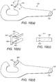
- an alternative third engagement portion 700 of the tool 100 is disclosed.
- the alternative third engagement portion 700 is suitable for moving a bead section 20 out of engagement with a rim 12.
- the alternative third engagement portion 700 is located at the second end of the handle portion 102, comprising two opposing inclined surfaces 702 arranged generally transverse with respect to the longitudinal axis 118 on respective surfaces of the handle portion 102.
- the two opposing inclined surfaces 702 are arranged so as to converge towards one edge of the handle portion 102, i.e. forming a "wedge".
- the inclined surfaces 702 are formed by two opposing grooves cut into respective surfaces of the handle portion 102.
- the angular alignment of the longitudinal axis 704 of one groove 702 may be offset with respect to the angular alignment of the longitudinal axis of the other groove 702 (when viewed with regards to the longitudinal axis 118 of the tool 100), so that, during use, the bead portion 20 of the tyre is not only pushed up, but also out and away from the rim flanges 24, while the other groove 702 functions as a guide sliding on the rim flange 24 of the wheel.
- the third engagement portion 700 may also be tapered towards the end of the handle portion 102 so as to facilitate sliding the third engagement portion 700 between the rim flange 24 and the bead portion 20 of the tyre.
- the third engagement portion 700 is pushed in a space between the rim flange 24 and the bead portion 20 so that the lower groove 702 is in contact with the top of the rim flange 24.
- the handle portion 102 is then pivoted about the contact point of the lower groove 702 to lift the bead portion 20 into the upper groove 702.
- the handle portion 102 is then slid on the rim flange 24 in a direction towards the tapered edge of the two inclined surfaces 702, therefore sliding the bead portion up and out of engagement with the rim flange 24.
- the tool 100 is illustrated during tyre removal, where the portion 700 may be rotated about the longitudinal axis of the tool 100 such that the leading edge of groove 702 lifts a portion of the tyre bead 20 over the rim flange 24 of the wheel 10 in advance of portion 700, allowing the lever to be moved easily around the circumference of the wheel rim 24. It is understood by the person skilled in the art that the opposite end portion of the lever tool 100 is used as a handle providing additional torque and leverage to assist the user when removing the tyre.
Landscapes
- Engineering & Computer Science (AREA)
- Mechanical Engineering (AREA)
- Tires In General (AREA)
Claims (15)
- Un outil (100) pour installer et retirer un pneu ayant un talon, comprenant un élément formant corps substantiellement allongé ayant un axe longitudinal, l'élément formant corps comprenant en sus :une portion formant poignée (102), disposée dans l'alignement dudit axe longitudinal (118) ;une première portion de mise en prise (108), disposée au niveau d'une première extrémité (104) de ladite portion formant poignée, conçue afin de se mettre en prise de façon opérationnelle avec une première collerette parmi des première et deuxième collerettes de jante opposées (24) d'une roue, de façon à former un point d'appui sur le point de contact avec la première collerette ;une deuxième portion de mise en prise (112), espacée selon une distance prédéterminée dans une direction s'éloignant de ladite première portion de mise en prise le long dudit axe longitudinal, conçue pour se mettre en prise de façon contiguë avec une portion de talon chevauchant une jante d'un pneu, de façon à déplacer la portion de talon (20) par-dessus la deuxième collerette parmi les première et deuxième collerettes de jante opposées pendant l'utilisation ;une portion formant pont (110), reliant de façon opérationnelle ladite première portion de mise en prise et ladite deuxième portion de mise en prise, conçue afin d'accueillir une gamme prédéterminée de profils en coupe transversale d'un pneu pendant l'utilisation, etcaractérisé en ce que ladite première portion de mise en prise comprend une première surface de contact plane (116) pouvant être placée sur la première collerette (24), dans lequel ladite première surface de contact plane (116) fait face à ladite deuxième portion de mise en prise et est disposée selon un angle aigu prédéterminé (α) par rapport audit axe longitudinal.
- Un outil selon n'importe laquelle des revendications précédentes, dans lequel ladite deuxième portion de mise en prise comprend une portion formant bord faisant saillie en direction dudit premier élément de mise en prise.
- Un outil selon la revendication 2, dans lequel ladite portion formant bord comprend en sus une deuxième surface de contact plane (122) disposée de façon substantiellement perpendiculaire par rapport à la surface extérieure de la deuxième collerette quand elle entre en contact avec la surface extérieure de la collerette pendant l'utilisation.
- Un outil selon n'importe laquelle des revendications précédentes, dans lequel ladite première portion de mise en prise comprend en sus au moins un élément de surface de contact interchangeable (600), ayant une troisième surface de contact plane (606), et qui est conçu afin d'être fixé de façon amovible à ladite première portion de mise en prise.
- Un outil selon la revendication 4, dans lequel ladite troisième surface de contact plane est disposée selon ledit angle prédéterminé par rapport audit axe longitudinal quand ledit au moins un élément de surface de contact interchangeable est fixé à ladite première portion de mise en prise.
- Un outil selon la revendication 4, dans lequel ledit au moins un élément de surface de contact interchangeable comprend en sus une portion de montage (604) conçue afin de se mettre en prise de façon démontable avec ladite première portion de mise en prise.
- Un outil selon n'importe laquelle des revendications précédentes, dans lequel ladite portion formant poignée, ladite première portion de mise en prise, ladite deuxième portion de mise en prise et ladite portion formant pont sont des parties solidaires dudit élément formant corps.
- Un outil selon n'importe laquelle des revendications 1 à 6, comprenant en sus au moins un mécanisme de réglage (200, 300, 400, 600) conçu afin de déplacer de façon sélective ladite première portion de mise en prise et/ou ladite deuxième portion de mise en prise, de façon à augmenter ou réduire ladite distance prédéterminée entre ladite première portion de mise en prise et ladite deuxième portion de mise en prise.
- Un outil selon la revendication 8, dans lequel ledit au moins un mécanisme de réglage est incorporé de façon opérationnelle à l'intérieur de ladite portion formant pont et/ou entre ladite première portion de mise en prise et ladite portion formant poignée.
- Un outil selon n'importe laquelle des revendications 8 et 9, dans lequel ledit mécanisme de réglage comprend n'importe quel élément parmi un mécanisme à vis pouvant être verrouillé de façon sélective et/ou une articulation pivot pouvant être verrouillée de façon sélective et/ou un mécanisme à rochet pouvant être verrouillé de façon sélective.
- Un outil selon n'importe laquelle des revendications précédentes, comprenant en sus une troisième portion de mise en prise (500, 700) disposée au niveau d'une deuxième extrémité (106) de ladite portion formant poignée, conçue afin de se mettre en prise de façon coopérative avec une portion de talon d'un pneu situé à l'intérieur d'une jante d'une roue et une portion de collerette adjacente d'une jante, de façon à soulever en faisant levier la portion de talon vers le haut et par-dessus la portion de collerette et à faire sortir la portion de talon de la jante pendant l'utilisation.
- Un outil selon la revendication 11, dans lequel ladite troisième portion de mise en prise comprend un premier renfoncement (502) conçu afin de se mettre en prise de façon à s'accoupler avec une portion de collerette de la jante de façon à former un point d'appui, et un deuxième renfoncement (504) conçu pour se mettre en prise de façon à s'accrocher avec une portion de talon du pneu.
- Un outil selon la revendication 12, dans lequel ledit premier renfoncement et ledit deuxième renfoncement sont situés sur des coins opposés de ladite deuxième extrémité de ladite portion formant poignée de façon à former un levier entre lesdits premier et deuxième renfoncements quand ledit premier renfoncement est mis en prise avec la portion de collerette de la jante pendant l'utilisation.
- Un outil selon la revendication 11, dans lequel ladite troisième portion de mise en prise comprend une surface inclinée (702) conçue pour déplacer la portion de talon d'un pneu vers le haut et par-dessus la portion de collerette quand ladite surface inclinée est déplacée dans une direction prédéterminée le long de la portion de collerette de la jante.
- Un outil selon la revendication 14, dans lequel ladite surface inclinée est fournie par deux rainures s'opposant sur des surfaces opposées de ladite troisième portion de mise en prise de façon à former un biseau avec une coupe transversale biconcave.
Applications Claiming Priority (3)
| Application Number | Priority Date | Filing Date | Title |
|---|---|---|---|
| GBGB1414255.8A GB201414255D0 (en) | 2014-08-12 | 2014-08-12 | A tyre removing and installation tool |
| GB1506767.1A GB2529280A (en) | 2014-08-12 | 2015-04-21 | A tyre removing and installation tool |
| PCT/GB2015/052274 WO2016024092A1 (fr) | 2014-08-12 | 2015-08-06 | Outil à main de démontage et de montage de pneumatique |
Publications (2)
| Publication Number | Publication Date |
|---|---|
| EP3180201A1 EP3180201A1 (fr) | 2017-06-21 |
| EP3180201B1 true EP3180201B1 (fr) | 2018-12-19 |
Family
ID=51629639
Family Applications (1)
| Application Number | Title | Priority Date | Filing Date |
|---|---|---|---|
| EP15749857.7A Active EP3180201B1 (fr) | 2014-08-12 | 2015-08-06 | Outil a main pour changer des pneus |
Country Status (5)
| Country | Link |
|---|---|
| US (1) | US10300750B2 (fr) |
| EP (1) | EP3180201B1 (fr) |
| ES (1) | ES2713396T3 (fr) |
| GB (2) | GB201414255D0 (fr) |
| WO (1) | WO2016024092A1 (fr) |
Families Citing this family (5)
| Publication number | Priority date | Publication date | Assignee | Title |
|---|---|---|---|---|
| CN107031320A (zh) * | 2017-05-15 | 2017-08-11 | 广州市耐动信息科技有限公司 | 一种免充气轮胎装胎机 |
| IT201700081299A1 (it) * | 2017-07-18 | 2019-01-18 | Rosmeri S R L | Utensile per il montaggio e smontaggio di copertoni per biciclette |
| USD911794S1 (en) * | 2019-11-04 | 2021-03-02 | Product Development Resource, LLC | Bike tire tool |
| USD963443S1 (en) * | 2019-11-04 | 2022-09-13 | Product Development Resource, LLC | Bike tire multi tool |
| USD1113591S1 (en) | 2025-05-07 | 2026-02-17 | Nicholas John Ackermann | Bicycle tire tool |
Family Cites Families (24)
| Publication number | Priority date | Publication date | Assignee | Title |
|---|---|---|---|---|
| BE434738A (fr) | ||||
| US929905A (en) * | 1908-12-15 | 1909-08-03 | Arthur Courtis Webber | Tire-tool. |
| US1330648A (en) * | 1918-11-21 | 1920-02-10 | Clarence L Nickle | Tongs |
| GB143403A (en) | 1919-06-05 | 1920-05-27 | William John Owens | Improved devices for placing pneumatic tyres on wheel rims and for removing them |
| FR506081A (fr) * | 1919-11-03 | 1920-08-13 | Moise Duprat | Remonte-pneu pour bicyclette |
| US1392591A (en) * | 1920-02-18 | 1921-10-04 | Mobley Ora | Tire-tool |
| US1439381A (en) * | 1920-04-19 | 1922-12-19 | Gustaf A Safstrom | Tire tool |
| US1372796A (en) | 1920-07-24 | 1921-03-29 | Bjornlie Mfg Company | Tire-tool |
| GB191134A (en) * | 1921-10-04 | 1923-01-04 | Frederick Tom Goddard | Improvements in or relating to tyre levers |
| FR543526A (fr) * | 1921-11-14 | 1922-09-05 | Levier perfectionné pour le montage des enveloppes de pneumatiques | |
| GB200037A (en) * | 1922-10-19 | 1923-07-05 | Thomas Ginley | Improvements relating to tyre levers |
| FR586711A (fr) * | 1924-09-30 | 1925-04-02 | Outil pour remonter les pneumatiques | |
| US1791681A (en) * | 1929-06-17 | 1931-02-10 | Purley V Morgan | Device for removing tire shoes from drop-center rims |
| FR724232A (fr) | 1930-12-19 | 1932-04-23 | Nouvelle pince pour toutes applications, mais plus spécialement utilisable pour monter et démonter les bandages des roues des véhicules | |
| US2009338A (en) * | 1934-07-24 | 1935-07-23 | Orville C Brown | Tire tool |
| US2061274A (en) * | 1935-10-12 | 1936-11-17 | Horn Emil | Tire wrench |
| US2333880A (en) * | 1941-12-03 | 1943-11-09 | Ohlsen Hans Christian | Tire tool |
| FR878330A (fr) | 1942-01-08 | 1943-01-18 | Pince pour montage des enveloppes pneumatiques sur leur jante | |
| FR908320A (fr) | 1944-12-20 | 1946-04-05 | Remonte pneumatiques | |
| US2492329A (en) * | 1945-12-26 | 1949-12-27 | Blanchard D Smith | Hand tire tool for manipulating casings |
| US2481764A (en) * | 1946-09-23 | 1949-09-13 | Bradley O Luton | Hand tool for loosening and forcing tire beads into rim centers |
| US2582869A (en) * | 1946-11-21 | 1952-01-15 | Connie H Honeycutt | Axially collapsing type tire removing hand tool |
| ITMO20010024U1 (it) * | 2001-06-26 | 2002-12-26 | Sicam Srl | Attrezzo per agevolare le operazioni di smontaggio e rimontaggio dei pneumatici sui cerchi |
| US9610811B2 (en) * | 2014-12-01 | 2017-04-04 | Scott Wu | Tire tool |
-
2014
- 2014-08-12 GB GBGB1414255.8A patent/GB201414255D0/en not_active Ceased
-
2015
- 2015-04-21 GB GB1506767.1A patent/GB2529280A/en not_active Withdrawn
- 2015-08-06 EP EP15749857.7A patent/EP3180201B1/fr active Active
- 2015-08-06 US US15/501,075 patent/US10300750B2/en active Active
- 2015-08-06 ES ES15749857T patent/ES2713396T3/es active Active
- 2015-08-06 WO PCT/GB2015/052274 patent/WO2016024092A1/fr not_active Ceased
Non-Patent Citations (1)
| Title |
|---|
| None * |
Also Published As
| Publication number | Publication date |
|---|---|
| GB201506767D0 (en) | 2015-06-03 |
| GB201414255D0 (en) | 2014-09-24 |
| WO2016024092A1 (fr) | 2016-02-18 |
| EP3180201A1 (fr) | 2017-06-21 |
| GB2529280A (en) | 2016-02-17 |
| US10300750B2 (en) | 2019-05-28 |
| ES2713396T3 (es) | 2019-05-21 |
| US20170253095A1 (en) | 2017-09-07 |
Similar Documents
| Publication | Publication Date | Title |
|---|---|---|
| EP3180201B1 (fr) | Outil a main pour changer des pneus | |
| EP1674305B1 (fr) | Outil démonte-pneumatique | |
| US8931150B2 (en) | Spring attachment tool for air brake shoes | |
| US7866365B2 (en) | Portable tire demounting tool | |
| US6032497A (en) | Vehicle immobilizer with self-positioning tire shop | |
| CA2905152C (fr) | Outil pour chaine de pneu | |
| US7163041B1 (en) | Tire installation and removal tool | |
| WO1998013221A1 (fr) | Demonte-pneu de bicyclette ameliore | |
| US7261136B1 (en) | Tire mounting tool | |
| US7793699B2 (en) | Apparatus for mounting tires on large wheels | |
| US597286A (en) | John horswill | |
| US9434220B2 (en) | Tire demounting tool for deep-dish wheel rims | |
| CN117203068A (zh) | 轮胎安装工具 | |
| US9707808B2 (en) | Tire removal tool | |
| EP2078625B1 (fr) | Appareil pour faciliter le montage ou le démontage d'un pneumatique de vehicule | |
| US2252108A (en) | Tire tool | |
| US792009A (en) | Tool for applying clincher-tire casings to clincher-rims. | |
| US20250033416A1 (en) | Non-pneumatic tire and a system and method of making same | |
| US20250282187A1 (en) | Tool | |
| US6863110B1 (en) | Method and apparatus for removing vehicle wheel | |
| US7334623B2 (en) | Tire mounting and demounting bar | |
| MXPA06011744A (en) | Improved tire installation and removal tool |
Legal Events
| Date | Code | Title | Description |
|---|---|---|---|
| STAA | Information on the status of an ep patent application or granted ep patent |
Free format text: STATUS: THE INTERNATIONAL PUBLICATION HAS BEEN MADE |
|
| PUAI | Public reference made under article 153(3) epc to a published international application that has entered the european phase |
Free format text: ORIGINAL CODE: 0009012 |
|
| STAA | Information on the status of an ep patent application or granted ep patent |
Free format text: STATUS: REQUEST FOR EXAMINATION WAS MADE |
|
| 17P | Request for examination filed |
Effective date: 20170126 |
|
| AK | Designated contracting states |
Kind code of ref document: A1 Designated state(s): AL AT BE BG CH CY CZ DE DK EE ES FI FR GB GR HR HU IE IS IT LI LT LU LV MC MK MT NL NO PL PT RO RS SE SI SK SM TR |
|
| AX | Request for extension of the european patent |
Extension state: BA ME |
|
| DAV | Request for validation of the european patent (deleted) | ||
| DAX | Request for extension of the european patent (deleted) | ||
| RIC1 | Information provided on ipc code assigned before grant |
Ipc: B25D 1/00 20060101ALI20171124BHEP Ipc: B60C 25/01 20060101ALI20171124BHEP Ipc: B60C 25/02 20060101AFI20171124BHEP |
|
| GRAP | Despatch of communication of intention to grant a patent |
Free format text: ORIGINAL CODE: EPIDOSNIGR1 |
|
| STAA | Information on the status of an ep patent application or granted ep patent |
Free format text: STATUS: GRANT OF PATENT IS INTENDED |
|
| INTG | Intention to grant announced |
Effective date: 20180109 |
|
| GRAS | Grant fee paid |
Free format text: ORIGINAL CODE: EPIDOSNIGR3 |
|
| GRAJ | Information related to disapproval of communication of intention to grant by the applicant or resumption of examination proceedings by the epo deleted |
Free format text: ORIGINAL CODE: EPIDOSDIGR1 |
|
| GRAL | Information related to payment of fee for publishing/printing deleted |
Free format text: ORIGINAL CODE: EPIDOSDIGR3 |
|
| STAA | Information on the status of an ep patent application or granted ep patent |
Free format text: STATUS: REQUEST FOR EXAMINATION WAS MADE |
|
| INTC | Intention to grant announced (deleted) | ||
| GRAP | Despatch of communication of intention to grant a patent |
Free format text: ORIGINAL CODE: EPIDOSNIGR1 |
|
| STAA | Information on the status of an ep patent application or granted ep patent |
Free format text: STATUS: GRANT OF PATENT IS INTENDED |
|
| INTG | Intention to grant announced |
Effective date: 20180713 |
|
| GRAA | (expected) grant |
Free format text: ORIGINAL CODE: 0009210 |
|
| STAA | Information on the status of an ep patent application or granted ep patent |
Free format text: STATUS: THE PATENT HAS BEEN GRANTED |
|
| AK | Designated contracting states |
Kind code of ref document: B1 Designated state(s): AL AT BE BG CH CY CZ DE DK EE ES FI FR GB GR HR HU IE IS IT LI LT LU LV MC MK MT NL NO PL PT RO RS SE SI SK SM TR |
|
| REG | Reference to a national code |
Ref country code: GB Ref legal event code: FG4D |
|
| REG | Reference to a national code |
Ref country code: CH Ref legal event code: EP |
|
| REG | Reference to a national code |
Ref country code: IE Ref legal event code: FG4D |
|
| REG | Reference to a national code |
Ref country code: DE Ref legal event code: R096 Ref document number: 602015021911 Country of ref document: DE |
|
| REG | Reference to a national code |
Ref country code: AT Ref legal event code: REF Ref document number: 1078294 Country of ref document: AT Kind code of ref document: T Effective date: 20190115 |
|
| REG | Reference to a national code |
Ref country code: CH Ref legal event code: NV Representative=s name: MURGITROYD AND COMPANY, CH |
|
| REG | Reference to a national code |
Ref country code: NL Ref legal event code: FP |
|
| PG25 | Lapsed in a contracting state [announced via postgrant information from national office to epo] |
Ref country code: LV Free format text: LAPSE BECAUSE OF FAILURE TO SUBMIT A TRANSLATION OF THE DESCRIPTION OR TO PAY THE FEE WITHIN THE PRESCRIBED TIME-LIMIT Effective date: 20181219 Ref country code: BG Free format text: LAPSE BECAUSE OF FAILURE TO SUBMIT A TRANSLATION OF THE DESCRIPTION OR TO PAY THE FEE WITHIN THE PRESCRIBED TIME-LIMIT Effective date: 20190319 Ref country code: LT Free format text: LAPSE BECAUSE OF FAILURE TO SUBMIT A TRANSLATION OF THE DESCRIPTION OR TO PAY THE FEE WITHIN THE PRESCRIBED TIME-LIMIT Effective date: 20181219 Ref country code: HR Free format text: LAPSE BECAUSE OF FAILURE TO SUBMIT A TRANSLATION OF THE DESCRIPTION OR TO PAY THE FEE WITHIN THE PRESCRIBED TIME-LIMIT Effective date: 20181219 Ref country code: NO Free format text: LAPSE BECAUSE OF FAILURE TO SUBMIT A TRANSLATION OF THE DESCRIPTION OR TO PAY THE FEE WITHIN THE PRESCRIBED TIME-LIMIT Effective date: 20190319 Ref country code: FI Free format text: LAPSE BECAUSE OF FAILURE TO SUBMIT A TRANSLATION OF THE DESCRIPTION OR TO PAY THE FEE WITHIN THE PRESCRIBED TIME-LIMIT Effective date: 20181219 |
|
| REG | Reference to a national code |
Ref country code: LT Ref legal event code: MG4D |
|
| REG | Reference to a national code |
Ref country code: AT Ref legal event code: MK05 Ref document number: 1078294 Country of ref document: AT Kind code of ref document: T Effective date: 20181219 |
|
| REG | Reference to a national code |
Ref country code: ES Ref legal event code: FG2A Ref document number: 2713396 Country of ref document: ES Kind code of ref document: T3 Effective date: 20190521 |
|
| PG25 | Lapsed in a contracting state [announced via postgrant information from national office to epo] |
Ref country code: SE Free format text: LAPSE BECAUSE OF FAILURE TO SUBMIT A TRANSLATION OF THE DESCRIPTION OR TO PAY THE FEE WITHIN THE PRESCRIBED TIME-LIMIT Effective date: 20181219 Ref country code: RS Free format text: LAPSE BECAUSE OF FAILURE TO SUBMIT A TRANSLATION OF THE DESCRIPTION OR TO PAY THE FEE WITHIN THE PRESCRIBED TIME-LIMIT Effective date: 20181219 Ref country code: AL Free format text: LAPSE BECAUSE OF FAILURE TO SUBMIT A TRANSLATION OF THE DESCRIPTION OR TO PAY THE FEE WITHIN THE PRESCRIBED TIME-LIMIT Effective date: 20181219 Ref country code: GR Free format text: LAPSE BECAUSE OF FAILURE TO SUBMIT A TRANSLATION OF THE DESCRIPTION OR TO PAY THE FEE WITHIN THE PRESCRIBED TIME-LIMIT Effective date: 20190320 |
|
| PG25 | Lapsed in a contracting state [announced via postgrant information from national office to epo] |
Ref country code: PL Free format text: LAPSE BECAUSE OF FAILURE TO SUBMIT A TRANSLATION OF THE DESCRIPTION OR TO PAY THE FEE WITHIN THE PRESCRIBED TIME-LIMIT Effective date: 20181219 Ref country code: CZ Free format text: LAPSE BECAUSE OF FAILURE TO SUBMIT A TRANSLATION OF THE DESCRIPTION OR TO PAY THE FEE WITHIN THE PRESCRIBED TIME-LIMIT Effective date: 20181219 Ref country code: PT Free format text: LAPSE BECAUSE OF FAILURE TO SUBMIT A TRANSLATION OF THE DESCRIPTION OR TO PAY THE FEE WITHIN THE PRESCRIBED TIME-LIMIT Effective date: 20190419 |
|
| PG25 | Lapsed in a contracting state [announced via postgrant information from national office to epo] |
Ref country code: SM Free format text: LAPSE BECAUSE OF FAILURE TO SUBMIT A TRANSLATION OF THE DESCRIPTION OR TO PAY THE FEE WITHIN THE PRESCRIBED TIME-LIMIT Effective date: 20181219 Ref country code: EE Free format text: LAPSE BECAUSE OF FAILURE TO SUBMIT A TRANSLATION OF THE DESCRIPTION OR TO PAY THE FEE WITHIN THE PRESCRIBED TIME-LIMIT Effective date: 20181219 Ref country code: IS Free format text: LAPSE BECAUSE OF FAILURE TO SUBMIT A TRANSLATION OF THE DESCRIPTION OR TO PAY THE FEE WITHIN THE PRESCRIBED TIME-LIMIT Effective date: 20190419 Ref country code: RO Free format text: LAPSE BECAUSE OF FAILURE TO SUBMIT A TRANSLATION OF THE DESCRIPTION OR TO PAY THE FEE WITHIN THE PRESCRIBED TIME-LIMIT Effective date: 20181219 Ref country code: SK Free format text: LAPSE BECAUSE OF FAILURE TO SUBMIT A TRANSLATION OF THE DESCRIPTION OR TO PAY THE FEE WITHIN THE PRESCRIBED TIME-LIMIT Effective date: 20181219 |
|
| REG | Reference to a national code |
Ref country code: DE Ref legal event code: R097 Ref document number: 602015021911 Country of ref document: DE |
|
| PLBE | No opposition filed within time limit |
Free format text: ORIGINAL CODE: 0009261 |
|
| STAA | Information on the status of an ep patent application or granted ep patent |
Free format text: STATUS: NO OPPOSITION FILED WITHIN TIME LIMIT |
|
| PG25 | Lapsed in a contracting state [announced via postgrant information from national office to epo] |
Ref country code: DK Free format text: LAPSE BECAUSE OF FAILURE TO SUBMIT A TRANSLATION OF THE DESCRIPTION OR TO PAY THE FEE WITHIN THE PRESCRIBED TIME-LIMIT Effective date: 20181219 Ref country code: AT Free format text: LAPSE BECAUSE OF FAILURE TO SUBMIT A TRANSLATION OF THE DESCRIPTION OR TO PAY THE FEE WITHIN THE PRESCRIBED TIME-LIMIT Effective date: 20181219 |
|
| 26N | No opposition filed |
Effective date: 20190920 |
|
| PG25 | Lapsed in a contracting state [announced via postgrant information from national office to epo] |
Ref country code: SI Free format text: LAPSE BECAUSE OF FAILURE TO SUBMIT A TRANSLATION OF THE DESCRIPTION OR TO PAY THE FEE WITHIN THE PRESCRIBED TIME-LIMIT Effective date: 20181219 |
|
| PG25 | Lapsed in a contracting state [announced via postgrant information from national office to epo] |
Ref country code: TR Free format text: LAPSE BECAUSE OF FAILURE TO SUBMIT A TRANSLATION OF THE DESCRIPTION OR TO PAY THE FEE WITHIN THE PRESCRIBED TIME-LIMIT Effective date: 20181219 |
|
| PG25 | Lapsed in a contracting state [announced via postgrant information from national office to epo] |
Ref country code: LU Free format text: LAPSE BECAUSE OF NON-PAYMENT OF DUE FEES Effective date: 20190806 Ref country code: MC Free format text: LAPSE BECAUSE OF FAILURE TO SUBMIT A TRANSLATION OF THE DESCRIPTION OR TO PAY THE FEE WITHIN THE PRESCRIBED TIME-LIMIT Effective date: 20181219 |
|
| PG25 | Lapsed in a contracting state [announced via postgrant information from national office to epo] |
Ref country code: CY Free format text: LAPSE BECAUSE OF FAILURE TO SUBMIT A TRANSLATION OF THE DESCRIPTION OR TO PAY THE FEE WITHIN THE PRESCRIBED TIME-LIMIT Effective date: 20181219 |
|
| PG25 | Lapsed in a contracting state [announced via postgrant information from national office to epo] |
Ref country code: MT Free format text: LAPSE BECAUSE OF FAILURE TO SUBMIT A TRANSLATION OF THE DESCRIPTION OR TO PAY THE FEE WITHIN THE PRESCRIBED TIME-LIMIT Effective date: 20181219 Ref country code: HU Free format text: LAPSE BECAUSE OF FAILURE TO SUBMIT A TRANSLATION OF THE DESCRIPTION OR TO PAY THE FEE WITHIN THE PRESCRIBED TIME-LIMIT; INVALID AB INITIO Effective date: 20150806 |
|
| PG25 | Lapsed in a contracting state [announced via postgrant information from national office to epo] |
Ref country code: MK Free format text: LAPSE BECAUSE OF FAILURE TO SUBMIT A TRANSLATION OF THE DESCRIPTION OR TO PAY THE FEE WITHIN THE PRESCRIBED TIME-LIMIT Effective date: 20181219 |
|
| PGFP | Annual fee paid to national office [announced via postgrant information from national office to epo] |
Ref country code: NL Payment date: 20250827 Year of fee payment: 11 |
|
| PGFP | Annual fee paid to national office [announced via postgrant information from national office to epo] |
Ref country code: ES Payment date: 20250902 Year of fee payment: 11 |
|
| PGFP | Annual fee paid to national office [announced via postgrant information from national office to epo] |
Ref country code: DE Payment date: 20250828 Year of fee payment: 11 |
|
| PGFP | Annual fee paid to national office [announced via postgrant information from national office to epo] |
Ref country code: IT Payment date: 20250826 Year of fee payment: 11 |
|
| PGFP | Annual fee paid to national office [announced via postgrant information from national office to epo] |
Ref country code: BE Payment date: 20250825 Year of fee payment: 11 Ref country code: GB Payment date: 20250829 Year of fee payment: 11 |
|
| PGFP | Annual fee paid to national office [announced via postgrant information from national office to epo] |
Ref country code: FR Payment date: 20250827 Year of fee payment: 11 |
|
| PGFP | Annual fee paid to national office [announced via postgrant information from national office to epo] |
Ref country code: CH Payment date: 20250901 Year of fee payment: 11 |
|
| PGFP | Annual fee paid to national office [announced via postgrant information from national office to epo] |
Ref country code: IE Payment date: 20250829 Year of fee payment: 11 |