EP3181908A1 - Pompe centrifuge à plusieurs étages avec tirants d'ancrage en tôle - Google Patents
Pompe centrifuge à plusieurs étages avec tirants d'ancrage en tôle Download PDFInfo
- Publication number
- EP3181908A1 EP3181908A1 EP15200756.3A EP15200756A EP3181908A1 EP 3181908 A1 EP3181908 A1 EP 3181908A1 EP 15200756 A EP15200756 A EP 15200756A EP 3181908 A1 EP3181908 A1 EP 3181908A1
- Authority
- EP
- European Patent Office
- Prior art keywords
- centrifugal pump
- tie rods
- foot part
- pump according
- foot
- Prior art date
- Legal status (The legal status is an assumption and is not a legal conclusion. Google has not performed a legal analysis and makes no representation as to the accuracy of the status listed.)
- Granted
Links
Images


Classifications
-
- F—MECHANICAL ENGINEERING; LIGHTING; HEATING; WEAPONS; BLASTING
- F04—POSITIVE - DISPLACEMENT MACHINES FOR LIQUIDS; PUMPS FOR LIQUIDS OR ELASTIC FLUIDS
- F04D—NON-POSITIVE-DISPLACEMENT PUMPS
- F04D1/00—Radial-flow pumps, e.g. centrifugal pumps; Helico-centrifugal pumps
- F04D1/06—Multi-stage pumps
- F04D1/063—Multi-stage pumps of the vertically split casing type
- F04D1/066—Multi-stage pumps of the vertically split casing type the casing consisting of a plurality of annuli bolted together
-
- F—MECHANICAL ENGINEERING; LIGHTING; HEATING; WEAPONS; BLASTING
- F04—POSITIVE - DISPLACEMENT MACHINES FOR LIQUIDS; PUMPS FOR LIQUIDS OR ELASTIC FLUIDS
- F04D—NON-POSITIVE-DISPLACEMENT PUMPS
- F04D1/00—Radial-flow pumps, e.g. centrifugal pumps; Helico-centrifugal pumps
- F04D1/06—Multi-stage pumps
-
- F—MECHANICAL ENGINEERING; LIGHTING; HEATING; WEAPONS; BLASTING
- F04—POSITIVE - DISPLACEMENT MACHINES FOR LIQUIDS; PUMPS FOR LIQUIDS OR ELASTIC FLUIDS
- F04D—NON-POSITIVE-DISPLACEMENT PUMPS
- F04D29/00—Details, component parts, or accessories
- F04D29/40—Casings; Connections of working fluid
- F04D29/42—Casings; Connections of working fluid for radial or helico-centrifugal pumps
- F04D29/426—Casings; Connections of working fluid for radial or helico-centrifugal pumps especially adapted for liquid pumps
- F04D29/4293—Details of fluid inlet or outlet
-
- F—MECHANICAL ENGINEERING; LIGHTING; HEATING; WEAPONS; BLASTING
- F04—POSITIVE - DISPLACEMENT MACHINES FOR LIQUIDS; PUMPS FOR LIQUIDS OR ELASTIC FLUIDS
- F04D—NON-POSITIVE-DISPLACEMENT PUMPS
- F04D29/00—Details, component parts, or accessories
- F04D29/60—Mounting; Assembling; Disassembling
- F04D29/62—Mounting; Assembling; Disassembling of radial or helico-centrifugal pumps
- F04D29/628—Mounting; Assembling; Disassembling of radial or helico-centrifugal pumps especially adapted for liquid pumps
-
- F—MECHANICAL ENGINEERING; LIGHTING; HEATING; WEAPONS; BLASTING
- F05—INDEXING SCHEMES RELATING TO ENGINES OR PUMPS IN VARIOUS SUBCLASSES OF CLASSES F01-F04
- F05D—INDEXING SCHEME FOR ASPECTS RELATING TO NON-POSITIVE-DISPLACEMENT MACHINES OR ENGINES, GAS-TURBINES OR JET-PROPULSION PLANTS
- F05D2230/00—Manufacture
- F05D2230/50—Building or constructing in particular ways
- F05D2230/54—Building or constructing in particular ways by sheet metal manufacturing
Definitions
- the invention relates to a multi-stage centrifugal pump with the features specified in the preamble of claim 1.
- centrifugal pumps are known in numerous design variants, in this context, reference is made in particular to the Grundfos CR series, which is available in different sizes on the market. Common to all these pumps is that they have a foot part, with which they stand in operation on the ground or a foundation provided for this purpose, and a head part, which is designed as a motor chair or is provided for receiving a motor chair, via which a drive motor for the Pump is connectable.
- these are pumps in which the actual centrifugal pump and the drive motor essentially form independent units, which are coupled to one another in the area of the motorized chair.
- Normally standard motors are used which are not specially designed for these pumps, but which can also be used in other drive applications.
- This centrifugal pump must therefore be structurally designed so that it can accommodate floor mounted the drive motor mounted on the head part and its reaction forces.
- the centrifugal pumps are designed in series, the head and foot parts match each, but differ in the number of interposed pump stages.
- tie rods that give the pump the mechanical cohesion.
- tie rods are provided, which are formed from round material and are provided at the ends with an external thread.
- These tie rods are either fixed in threaded holes of the foot or fastened there by nuts, the headboard side, the free ends of the tie rods are guided through corresponding holes in the head and nuts are set there.
- This tie rods thus integrated between the headboard and footboard pump stages are clamped together, whereby the entire structure gets its stability.
- a disadvantage of multi-stage centrifugal pumps of this type is that the tie rods are quite expensive to assemble. So they must first be screwed in the foot, after which the connection is made with the head part and finally the headboard side nuts are placed and tightened with the required torque. Moreover, these helical tie rods are expensive and heavy. They are clearly projecting laterally relative to the cylindrical pump body, so that they always form attack surfaces on which it is easy to get caught with a tool or other objects. Due to the lateral projection on the pump body bending moments on the headboard and foot are also effective, which can lead to undesirable deformations.
- the invention has for its object to improve a multi-stage centrifugal pump of the type mentioned in terms of tie rods and their attachment.
- the multi-stage centrifugal pump according to the invention has a foot part and a head part, between which pump stages are incorporated.
- Headboard and footboard are connected together by tie rods which are fixed at one end to the headboard and at the other end to the footboard, the tie rods being threaded at one end with which they are braced at the headboard or at the footboard.
- the tie rods are at least partially formed from sheet metal and have at least at the other end, ie at the non-threaded end at least one recess in the sheet, with which they are fixed at least in the pulling direction positively on the foot or on the headboard.
- centrifugal pumps of the type in question here have a foot, with which they stand up on the ground or a foundation, that is, a component that carries the entire pump and the motor connected thereto.
- the tie rods are at least partially formed from sheet metal, preferably up to the threaded portion at one end completely made of sheet metal.
- the tie rods should as far as possible be formed of sheet metal, that is, the threaded portion should be formed as short as necessary.
- the sheet metal part should thus bridge the entire area between the headboard and footboard or end immediately before the head or footboard, where then joins the threaded portion.
- Such tie rods formed from sheet metal can be produced inexpensively, for example by laser cutting or punching, which is particularly advantageous in large quantities.
- connection is made on one side form-fitting manner by means of the at least one recess, either on the foot part or on the head part, preferably on the foot part, so that the thread is arranged headboard side and bolted there with a nut.
- the extensive design of the tie rods made of sheet metal also has the advantage that they can be adapted to the outer contour of the pump stages, whereby the radial size in the pump stages can be significantly reduced. As a result, the known in constructions according to the prior art torque loads of the head and foot can be significantly reduced.
- the design of the tie rods made of sheet metal also allows a much more aesthetically pleasing design than was the case in the prior art, in which the clamping bolts protrude externally body-like radially.
- the dimensioning of the tie rods depends on the forces to be absorbed and the tensile strength of the material used. However, they should advantageously be at least dimensioned so that an inherent stability of the tie rods is given. This can also be supported, for example, by the fact that the tie rods have a curvature adapted to the curvature of the pump body, ie are bent around their longitudinal axis. Such a curvature makes it possible to apply the tie rods practically without any spacing to the pump body formed in the region of the pump stages, so that these, which is particularly advantageous, have the same temperature level as the pump body.
- the determination of the end formed of sheet metal is carried out according to the invention by means of at least one recess into which engages a correspondingly provided on the foot or head part projection. If the recess is completely within the sheet, a peg-like or hook-like projection is provided on the foot or head part side, in order to obtain a positive connection in the pulling direction.
- a pin may, for example, lie within an anchor recess of the foot part or be formed at a suitable location on the foot part.
- the recesses are referred to below, which are provided for the positive fixing, ie for anchoring the end formed of sheet metal of a tie rod and are determined.
- recesses In contrast to the recesses in the end formed of sheet metal of a tie rod hereinafter referred to only as recesses. It may be either recesses in the form of holes within the sheet or lateral recesses.
- the recesses in the head part are referred to below as hole recesses in which the headboard ends of the tie rods are fixed. These may be holes, holes or laterally open recesses.
- the tie rods each have a recess on at least one longitudinal side.
- a positive fixing in the head or foot part can be done by designing a corresponding anchor recess, which has an area in which the tie rod is inserted and has another area at which a counter part engages in this recess. This state can be achieved, for example, by pivoting, transverse shifting or turning.
- lateral recesses are provided on both longitudinal sides of the tie rod, preferably on same height, then there is a particularly uniform force in the tie rod.
- the threaded end of the tie rod made of sheet metal, in which further material is applied to the sheet metal body either by folding or by applying, in which then a thread is cut or stamped.
- a threaded bolt which is connected to the formed part of the tie rod by welding.
- hole recesses through which the threaded ends of the tie rods are guided and fixed and braced there by means of a respective nut.
- This attachment is advantageously headboard side, wherein the head part is advantageously designed as a motor chair. It is then the same component which not only closes the pump steps upwards, but at the same time also forms the motor mount.
- the hole recesses may be laterally open, so that it is not necessary to put the threaded ends of the tie rods through them, but that they can be inserted, for example, from the side. This facilitates in particular the automated assembly.
- the part of the pump clamped between the foot part and the head part has a cylindrical section, for example formed by a tube which forms the return channel from the pressure side back to the foot part.
- a cylindrical section for example formed by a tube which forms the return channel from the pressure side back to the foot part.
- the tie rods can also be arranged at a distance, even with this arrangement, a technically and optically advantageous design may result.
- anchor recesses are preferably provided in the foot part, each having an insertion part and a holding part.
- the insertion part is designed so that a sheet metal formed end of a tie rod can be passed through this insertion part and indeed so far until the recesses lie on the longitudinal sides within these Ankeraus foundedept. Then, by moving or pivoting a tie rod can be transferred with its blechteil solutionen end of the insertion part of an anchor recess in the holding part, in which the tie rod is held positively at least in the direction of its longitudinal axis and in which the surrounding the anchor recesses material laterally into the recesses of the blechteil paragraphen end engages the tie rod.
- the transfer from the insertion part in the holding part can advantageously be carried out by radial displacement or in a simple manner by pivoting, as will be described in detail below.
- the anchor recesses are designed so that the holding parts radially outwardly adjoin the insertion parts, so that the cylindrical portion of the surrounding pump stages secure the ends of the tie rods, which lie in the Hal former the Ankeraus strictly aus, positively, so that they no longer in reach the area of the insertion parts, in which they can be pushed through for assembly or disassembly purposes.
- anchor recesses are arranged in a circle around the longitudinal center axis of the pump, preferably in the foot part, and their insertion parts are covered by a component of the pump, for example a pump stage or the circumferential jacket, for positive fixing of the tie rod located in the holding part.
- the tie rods are advantageously arranged symmetrically about the longitudinal center and axis of rotation of the pump around, there may be provided three, four or more tie rods.
- the anchor recesses are arranged in an axial wall, preferably of the foot part.
- the actual foot can consist of a plate, for example, made of cast iron and an upwardly adjoining part either also made of cast, so be designed as a one-piece component with the plate or possibly also as a sheet metal construction.
- the insertion parts of the anchor recesses are arranged in a radial wall and the holding parts of the anchor recesses in an axial wall, preferably of the foot part.
- Such an arrangement has the advantage that the tie rods can be inserted from the side and fixed in a form-fitting manner, for example by pivoting. This results in a very simple and reliable installation.
- the holding parts of the anchor recesses may alternatively be provided in a corresponding recess or recess in the radial wall, typically in its peripheral side.
- both the head part and the foot part are formed as a metallic casting, wherein the foot part for setting up the pump on a foundation, typically on the ground, formed is and the head part for receiving an electric motor driving the pump is formed.
- These components can then be used for a whole series of pumps, wherein only the tie rods and the incorporated therebetween pump stages or the surrounding the return channel forming pipe must be adjusted according to the number of pump stage.
- the pump is advantageously designed as an in-line pump and has a suction port and a pressure port in the foot part, wherein the pump stages are surrounded by an annular channel through which the last pump stage is connected to the pressure port in the foot and the outer channel wall either adjacent or
- the tie rods are arranged at a small distance.
- the foot part can be formed with its suction and pressure connection as a casting, but it can also be constructed, for example, only the actual foot part forming plate made of cast iron and the rest of the foot part of sheet metal.
- tie rods are formed except for the threaded end portion of sheet metal, so the sheet metal part of the tie rod extends from the foot to the head or right up to it.
- the tie rods lie almost flush with the otherwise there cylindrical pump body. It when the tie rods are integrally formed and in particular also intrinsically stable, since then they are relatively easily einliederbar in largely automated assembly processes is particularly advantageous.
- the foot part has a cup-shaped structure, wherein the anchor recesses are then advantageously arranged where the pot bottom merges into the pot wall. It may then be provided, for example, the insertion part of the anchor recesses in the wall and the holding part in the ground. The anchor recess then extends into two areas. If the foot part is fluid-conducting and for this reason the inner side of the pot wall can not be provided with anchor recesses, the pot base can protrude radially beyond the pot wall, in order accordingly to arrange anchor recesses on the outside.
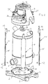
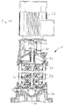
- the illustrated centrifugal pump 1 is a multi-stage centrifugal pump of the inline type (see also Fig. 11 ). It has a foot part 2, which is provided with its underside for placement on the floor or a corresponding foundation.
- the foot part 2 has substantially the shape of a rectangular plate which has four mounting recesses 3 at its corners, with which the foot part 2 can be screwed to the foundation, guided in the corresponding head screws through these recesses 3 and anchored in the foundation.
- the foot part 2 has a circular receptacle 4, which is provided for receiving a suction port 5 and a pressure port 6 exhibiting component which receives it upwardly subsequent pump stages, which are closed at the top by a cover part 7.
- a cylindrical pipe section 8 is arranged, which surrounds the pump stages at a distance and forms an annular channel through which the exiting at the end of the last pump stage liquid is led to the pressure port 6.
- the pump is closed by a head part 9, which at the same time forms a motor chair for an electric motor which can be flanged there.
- the suction and pressure connection 5, 6 having component, the adjoining pump stages, the surrounding pipe section 8 and the cover part 7 are clamped between the foot part 2 and the head part 9 positive and non-positive, by four symmetrically about the longitudinal
- These tie rods 11 are made of sheet metal and have an elongated narrow shape, they are bent about their longitudinal axis, corresponding to the curvature of the pipe section 8, so that they like Fig. 1 it can be seen that they continue to the outside.
- the tie rods 11 have a lower end 12, which is also formed of sheet metal and an upper end 13, which is formed by an externally threaded pin 14 which is firmly connected by welding to the upper end of the formed part of the tie rod 11 is.
- the sheet metal section 15 is provided with two recesses 16 on its longitudinal side, which are arranged at the same height, the underside of which is recessed 90 ° inwards and their upper side tapers obliquely to the outer edge of the sheet metal section 15.
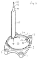
- four anchor holes 18 are provided in the foot part 2, namely at the edge of the receptacle 4, in the axial wall 17, whose contour is best in Fig. 4 is recognizable.
- Each anchor recess has an insertion part 19 and a holding part 20, which are matched to the lower end 12 of a tie rod.
- the insertion part 19 is dimensioned so that it corresponds to the cross-sectional area of the sheet metal section 15, that is, a tie rod 11 with its lower end 12 from above into the insertion part 19 can be inserted and passed.
- This lower end 12 is inserted so far into the insertion part 19 until the recesses 16 are arranged at the height of the anchor recess 18, then the tie rod 11 is displaced radially outwardly in the anchor recess 18, so that the comparatively narrow web part 21, which is between the Recesses 16 is formed in the sheet metal section 15, in the holding part 20 of the anchor recess 18 passes, whereby the tie rod 11 is positively fixed in the pulling direction 22 in the foot part 2.
- the receptacle 4 which is provided in terms of their dimensions for receiving the suction and pressure port 5, 6 receiving component, this component after incorporation of the tie rods 11 still record, but with the effect that by incorporating the component in the recording 4, the insertion parts 9 of the anchor recesses 18 closed and thus the lower ends 12 of the tie rods 11 are positively fixed within the foot part 2.
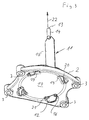
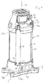
- the pipe section 8 which defines the annular channel to the outside, between the foot part 2a and the head part 9a.
- the structure in detail arises in particular from Fig. 7 , In this construction, the head and foot parts 9a, 2a made of castings are not lined with stainless steel sheet as in the above-described embodiment, but form parts of the flow channels.
- the basic structure is similar, but the receptacle 4a is formed closed, that is without recess on the inside. This is necessary to ensure the tightness relative to the pipe section 8.
- the receptacle 4a surrounding anchor recesses 18a are provided, which are arranged on the outside of the receptacle 4a and having a radial insertion part 19a and an axial holding part 20a.
- the radial insertion part 19a of an armature recess 18a lies in a radial wall 23a, which surrounds the receptacle 4a at a distance and receives the pressure and the suction connection 5, 6.
- This radial wall 23a is stepped at its upper end in an axial wall 17a, which is not part of the receptacle 4a, but forms an outer shoulder.
- the tie rods 11 themselves are designed exactly as in the previously described embodiment. They will be here, however, as in particular Fig. 6 can be seen, obliquely from the outside and up through the insertion part 19a, so the Ankeraus Principleungsteil inserted in the radial wall 23a until the recesses 16 and the web 21 of the tie rods 11 are arranged at the level of the holding parts 20a of the anchor recesses 18a.
- the tie rod 11 is pivoted obliquely upward until it rests parallel to the pipe section 8 at a distance and the threaded bolt 14 engages in the laterally open hole recess 24a, with respect to the upper end, he as in the previous embodiment under inclusion of a Washer screwed with a nut 25 and thus fixed.
- the narrow sheet metal portion 21 passes between the recesses 16 in the region of the holding part 20a of the anchor recess 18a in the axial wall 17a, whereby the parts of the projecting parts of the Sheet metal section 15 received a positive connection in the pulling direction 22 and in the opposite direction.
- the tie rod 11 is held in this position by the threaded bolt 14 defined by the nut 25, with which the upper end 14 of the tie rod 11 is fastened to the head part 9a.
- the holding part 20a of an anchor recess 18a is provided in the above-described embodiment in the axial wall 17a, but it can also be provided this part of the anchor recess 18a in the radial wall 23a, if this dimensioned accordingly and one matched to the lower end 12 of the tie rod 11 that is, in the form of corresponding recess or recess.
- the main advantage of the above-described arrangement is that the pump can be constructed almost completely starting from the foot part 2a to the head part 9a, after which the tie rods 11 are finally inserted into the anchor recesses 18a and secured there in a form-fitting manner by pivoting. The corresponding tensile stress between the foot 2a and the head part 9a is then applied by tightening the nut 25 with the intended torque.
- This design is therefore particularly advantageous for at least partially automated assembly.
- Fig. 11 is the basic structure of such a centrifugal pump with drive, which, as the break line in horizontal Direction clarified, stands for multi-stage centrifugal pumps with virtually any number of pump stages.
- a drive motor 26 in the form of an electric motor whose shaft 27 is rotatably connected to a shaft 28 of the centrifugal pump 1 by a coupling.
- On the drive shaft 28 of the centrifugal centrifugal impellers 29 are rotatably arranged according to the number of stages, which together with housing-fixed nozzles 30 form the pump stages.
- the delivery fluid will flow over the (in Fig. 11 not visible) suction connection 5 led to the suction port of the lowest pump stage and passes from there pump stage to pump stage with pressure increase upwards, where it exits within the head part 9a and is passed via an annular channel 31 back down to the foot part and there to the pressure port 6.
Landscapes
- Engineering & Computer Science (AREA)
- Mechanical Engineering (AREA)
- General Engineering & Computer Science (AREA)
- Structures Of Non-Positive Displacement Pumps (AREA)
Priority Applications (6)
| Application Number | Priority Date | Filing Date | Title |
|---|---|---|---|
| EP15200756.3A EP3181908B1 (fr) | 2015-12-17 | 2015-12-17 | Pompe centrifuge à plusierurs étages avec tirants d'ancrage en tôle |
| PCT/EP2016/080043 WO2017102491A1 (fr) | 2015-12-17 | 2016-12-07 | Pompe centrifuge multi-étagée comprenant des tirants d'ancrage constitués de tôle |
| CN201680074525.7A CN108368851B (zh) | 2015-12-17 | 2016-12-07 | 具有由片材构成的拉杆的多级离心泵 |
| DE202016008104.8U DE202016008104U1 (de) | 2015-12-17 | 2016-12-07 | Kreiselpumpe |
| US16/060,215 US10808703B2 (en) | 2015-12-17 | 2016-12-07 | Multi-stage centrifugal pump having tie rods formed from sheet metal |
| RU2018123322A RU2703428C1 (ru) | 2015-12-17 | 2016-12-07 | Многоступенчатый центробежный насос, имеющий стяжные анкеры, выполненные из листового металла |
Applications Claiming Priority (1)
| Application Number | Priority Date | Filing Date | Title |
|---|---|---|---|
| EP15200756.3A EP3181908B1 (fr) | 2015-12-17 | 2015-12-17 | Pompe centrifuge à plusierurs étages avec tirants d'ancrage en tôle |
Publications (2)
| Publication Number | Publication Date |
|---|---|
| EP3181908A1 true EP3181908A1 (fr) | 2017-06-21 |
| EP3181908B1 EP3181908B1 (fr) | 2020-05-13 |
Family
ID=54850262
Family Applications (1)
| Application Number | Title | Priority Date | Filing Date |
|---|---|---|---|
| EP15200756.3A Active EP3181908B1 (fr) | 2015-12-17 | 2015-12-17 | Pompe centrifuge à plusierurs étages avec tirants d'ancrage en tôle |
Country Status (6)
| Country | Link |
|---|---|
| US (1) | US10808703B2 (fr) |
| EP (1) | EP3181908B1 (fr) |
| CN (1) | CN108368851B (fr) |
| DE (1) | DE202016008104U1 (fr) |
| RU (1) | RU2703428C1 (fr) |
| WO (1) | WO2017102491A1 (fr) |
Cited By (3)
| Publication number | Priority date | Publication date | Assignee | Title |
|---|---|---|---|---|
| EP3670919A1 (fr) | 2018-12-20 | 2020-06-24 | Grundfos Holding A/S | Ensemble de pompe |
| EP4080058A1 (fr) | 2021-04-19 | 2022-10-26 | Grundfos Holding A/S | Ensemble pompe centrifuge |
| WO2025247888A1 (fr) | 2024-05-31 | 2025-12-04 | Grundfos Holding A/S | Composant de pompe pour ensemble pompe centrifuge |
Families Citing this family (5)
| Publication number | Priority date | Publication date | Assignee | Title |
|---|---|---|---|---|
| EP3434909B1 (fr) * | 2017-07-25 | 2023-09-27 | CIRCOR Pumps North America, LLC | Carter de pompe comportant une bride de support et une bride d'aspiration intégrales |
| US11585356B2 (en) | 2018-10-25 | 2023-02-21 | Pierburg Pump Technology Gmbh | Motor vehicle pump arrangement and mounting arrangement for a motor vehicle pump arrangement |
| USD936176S1 (en) * | 2019-08-12 | 2021-11-16 | Logical Concepts, Inc. | Submersible pump cage |
| IT202000004882A1 (it) * | 2020-03-09 | 2021-09-09 | Dab Pumps Spa | Elettropompa con camicia perfezionata |
| CN113294349A (zh) * | 2021-05-19 | 2021-08-24 | 广东瑞荣泵业有限公司 | 分段式冲压不锈钢井用潜水泵 |
Citations (5)
| Publication number | Priority date | Publication date | Assignee | Title |
|---|---|---|---|---|
| DE3410080C1 (de) * | 1984-03-20 | 1985-07-11 | Klein, Schanzlin & Becker Ag, 6710 Frankenthal | Raumsparendes Verbindungselement |
| DE29817337U1 (de) * | 1998-09-26 | 1998-12-17 | Grundfos A/S, Bjerringbro | Kreiselpumpe der Inline-Bauart zum Fördern heißer Flüssigkeiten |
| JP2001041187A (ja) * | 1999-07-30 | 2001-02-13 | Teral Kyokuto Inc | 深井戸用水中モータポンプ及びその吐出ケーシング又は逆止弁ケーシング |
| JP2003172285A (ja) * | 2001-11-30 | 2003-06-20 | Kawamoto Pump Mfg Co Ltd | 多段ポンプ用ケーシング固定バンドおよびそのケーシング固定バンドの製造方法 |
| EP2143959A1 (fr) * | 2008-07-10 | 2010-01-13 | Grundfos Management A/S | Groupe motopompe et procédé de création modulaire d'un groupe motopompe |
Family Cites Families (11)
| Publication number | Priority date | Publication date | Assignee | Title |
|---|---|---|---|---|
| US4339105A (en) * | 1980-06-16 | 1982-07-13 | Bell Telephone Laboratories, Incorporated | Clamp for securing large can-type capacitors to a circuit chassis |
| FR2661218B1 (fr) * | 1990-04-24 | 1992-07-31 | Salmson Pompes | Ensemble de pompe centrifuge verticale. |
| JP3052199B2 (ja) * | 1998-05-11 | 2000-06-12 | 株式会社テラルキヨクトウ | 遠心多段ポンプ |
| JP3953328B2 (ja) * | 2002-01-21 | 2007-08-08 | 株式会社荏原製作所 | 羽根車 |
| JP4633396B2 (ja) * | 2004-07-16 | 2011-02-16 | 株式会社荏原製作所 | 遠心式ポンプ |
| US7946810B2 (en) * | 2006-10-10 | 2011-05-24 | Grundfos Pumps Corporation | Multistage pump assembly |
| US8172523B2 (en) | 2006-10-10 | 2012-05-08 | Grudfos Pumps Corporation | Multistage pump assembly having removable cartridge |
| ITTO20110446A1 (it) * | 2011-05-19 | 2012-11-20 | Cosmogas Srl | Scambiatore di calore e procedimento di realizzazione |
| EP2607703B1 (fr) | 2011-12-22 | 2014-06-18 | Grundfos Holding A/S | Pompe centrifuge |
| ITPD20120284A1 (it) * | 2012-10-02 | 2014-04-03 | Dab Pumps Spa | Struttura di elettropompa centrifuga perfezionata |
| CN103846860A (zh) * | 2014-03-24 | 2014-06-11 | 瓮福(集团)有限责任公司 | 一种多级泵轴套快速拆卸装置 |
-
2015
- 2015-12-17 EP EP15200756.3A patent/EP3181908B1/fr active Active
-
2016
- 2016-12-07 DE DE202016008104.8U patent/DE202016008104U1/de active Active
- 2016-12-07 US US16/060,215 patent/US10808703B2/en active Active
- 2016-12-07 CN CN201680074525.7A patent/CN108368851B/zh active Active
- 2016-12-07 WO PCT/EP2016/080043 patent/WO2017102491A1/fr not_active Ceased
- 2016-12-07 RU RU2018123322A patent/RU2703428C1/ru active
Patent Citations (5)
| Publication number | Priority date | Publication date | Assignee | Title |
|---|---|---|---|---|
| DE3410080C1 (de) * | 1984-03-20 | 1985-07-11 | Klein, Schanzlin & Becker Ag, 6710 Frankenthal | Raumsparendes Verbindungselement |
| DE29817337U1 (de) * | 1998-09-26 | 1998-12-17 | Grundfos A/S, Bjerringbro | Kreiselpumpe der Inline-Bauart zum Fördern heißer Flüssigkeiten |
| JP2001041187A (ja) * | 1999-07-30 | 2001-02-13 | Teral Kyokuto Inc | 深井戸用水中モータポンプ及びその吐出ケーシング又は逆止弁ケーシング |
| JP2003172285A (ja) * | 2001-11-30 | 2003-06-20 | Kawamoto Pump Mfg Co Ltd | 多段ポンプ用ケーシング固定バンドおよびそのケーシング固定バンドの製造方法 |
| EP2143959A1 (fr) * | 2008-07-10 | 2010-01-13 | Grundfos Management A/S | Groupe motopompe et procédé de création modulaire d'un groupe motopompe |
Cited By (5)
| Publication number | Priority date | Publication date | Assignee | Title |
|---|---|---|---|---|
| EP3670919A1 (fr) | 2018-12-20 | 2020-06-24 | Grundfos Holding A/S | Ensemble de pompe |
| CN111350669A (zh) * | 2018-12-20 | 2020-06-30 | 格兰富控股联合股份公司 | 泵组件 |
| EP4080058A1 (fr) | 2021-04-19 | 2022-10-26 | Grundfos Holding A/S | Ensemble pompe centrifuge |
| US11879474B2 (en) | 2021-04-19 | 2024-01-23 | Grundfos Holding A/S | Centrifugal pump assembly |
| WO2025247888A1 (fr) | 2024-05-31 | 2025-12-04 | Grundfos Holding A/S | Composant de pompe pour ensemble pompe centrifuge |
Also Published As
| Publication number | Publication date |
|---|---|
| EP3181908B1 (fr) | 2020-05-13 |
| CN108368851A (zh) | 2018-08-03 |
| US10808703B2 (en) | 2020-10-20 |
| WO2017102491A1 (fr) | 2017-06-22 |
| RU2703428C1 (ru) | 2019-10-16 |
| DE202016008104U1 (de) | 2017-02-10 |
| US20180363659A1 (en) | 2018-12-20 |
| CN108368851B (zh) | 2021-07-13 |
Similar Documents
| Publication | Publication Date | Title |
|---|---|---|
| EP3181908B1 (fr) | Pompe centrifuge à plusierurs étages avec tirants d'ancrage en tôle | |
| EP2818721B1 (fr) | Pompe centrifuge | |
| DE102012212603A1 (de) | Arretiervorrichtung mit Wandschalungsbefestigungseinrichtung und Verfahren | |
| EP0805297A2 (fr) | Dispositif d'ancrage | |
| DE102012212600A1 (de) | Arretiervorrichtung mit Anschlag für Ankerstab und Verfahren | |
| EP2195480B1 (fr) | Lave-linge | |
| EP2046612A1 (fr) | Dispositif de levage | |
| EP3126575B1 (fr) | Corniche de pont et ensemble de fixation d'une corniche de pont | |
| DE19703495C2 (de) | Trogmischer | |
| EP1260639A2 (fr) | Support mural sur un cadre de montage | |
| DE102019201395A1 (de) | Wandschalung mit Hülse für Ankerlöcher, Hülse und Reinigungsverfahren | |
| EP2818722B1 (fr) | Pompe centrifuge | |
| EP1170509A2 (fr) | Connexion d'aspiration ou de refoulement d'une pompe centrifuge | |
| DE102006009602A1 (de) | Traganordnung eines Behälters an einem tragenden Bauteil eines Lastkraftwagens | |
| DE102004029557B4 (de) | Vertikales Kreiselpumpenaggregat | |
| EP3348742B1 (fr) | Dispositif destiné à supporter une plaque de façade sur une structure portante | |
| DE3006057A1 (de) | Schneckenpumpe mit unterer aufhaengung | |
| AT516179B1 (de) | Verbindungsbeschlag für die Längsverbindung zwischen Pfahlstücken | |
| DE102005046043B4 (de) | Befestigungsanordnung einer Messerklinge an einer Mischschnecke eines Futtermischwagens | |
| DE2507903A1 (de) | Rammpfahl, bestehend aus rammschaft und pfahlschuh mit verdraengerteil | |
| DE202009010497U1 (de) | Winkel zur Befestigung eines Bauelementes | |
| EP3399114A1 (fr) | Débitmètre pour la sortie d'un récipient de liquide | |
| EP1767087B1 (fr) | Dispositif de fixation d'une lame d'un vis de mélange pour un chariot mélangeur de fourrage | |
| DE102015007793A1 (de) | Verbindungselement für Bauteile eines Katzenkratzbaums und Katzenkratzbaum mit einem solchen Verbindungselement | |
| DE20022573U1 (de) | Kopfaufbau für das Gehäuse einer mehrstufigen Kreiselpumpe |
Legal Events
| Date | Code | Title | Description |
|---|---|---|---|
| PUAI | Public reference made under article 153(3) epc to a published international application that has entered the european phase |
Free format text: ORIGINAL CODE: 0009012 |
|
| STAA | Information on the status of an ep patent application or granted ep patent |
Free format text: STATUS: THE APPLICATION HAS BEEN PUBLISHED |
|
| AK | Designated contracting states |
Kind code of ref document: A1 Designated state(s): AL AT BE BG CH CY CZ DE DK EE ES FI FR GB GR HR HU IE IS IT LI LT LU LV MC MK MT NL NO PL PT RO RS SE SI SK SM TR |
|
| AX | Request for extension of the european patent |
Extension state: BA ME |
|
| STAA | Information on the status of an ep patent application or granted ep patent |
Free format text: STATUS: REQUEST FOR EXAMINATION WAS MADE |
|
| 17P | Request for examination filed |
Effective date: 20171220 |
|
| RBV | Designated contracting states (corrected) |
Designated state(s): AL AT BE BG CH CY CZ DE DK EE ES FI FR GB GR HR HU IE IS IT LI LT LU LV MC MK MT NL NO PL PT RO RS SE SI SK SM TR |
|
| GRAP | Despatch of communication of intention to grant a patent |
Free format text: ORIGINAL CODE: EPIDOSNIGR1 |
|
| STAA | Information on the status of an ep patent application or granted ep patent |
Free format text: STATUS: GRANT OF PATENT IS INTENDED |
|
| INTG | Intention to grant announced |
Effective date: 20191127 |
|
| GRAS | Grant fee paid |
Free format text: ORIGINAL CODE: EPIDOSNIGR3 |
|
| GRAJ | Information related to disapproval of communication of intention to grant by the applicant or resumption of examination proceedings by the epo deleted |
Free format text: ORIGINAL CODE: EPIDOSDIGR1 |
|
| GRAL | Information related to payment of fee for publishing/printing deleted |
Free format text: ORIGINAL CODE: EPIDOSDIGR3 |
|
| STAA | Information on the status of an ep patent application or granted ep patent |
Free format text: STATUS: REQUEST FOR EXAMINATION WAS MADE |
|
| GRAR | Information related to intention to grant a patent recorded |
Free format text: ORIGINAL CODE: EPIDOSNIGR71 |
|
| STAA | Information on the status of an ep patent application or granted ep patent |
Free format text: STATUS: GRANT OF PATENT IS INTENDED |
|
| GRAA | (expected) grant |
Free format text: ORIGINAL CODE: 0009210 |
|
| STAA | Information on the status of an ep patent application or granted ep patent |
Free format text: STATUS: THE PATENT HAS BEEN GRANTED |
|
| INTC | Intention to grant announced (deleted) | ||
| INTG | Intention to grant announced |
Effective date: 20200331 |
|
| AK | Designated contracting states |
Kind code of ref document: B1 Designated state(s): AL AT BE BG CH CY CZ DE DK EE ES FI FR GB GR HR HU IE IS IT LI LT LU LV MC MK MT NL NO PL PT RO RS SE SI SK SM TR |
|
| REG | Reference to a national code |
Ref country code: GB Ref legal event code: FG4D Free format text: NOT ENGLISH |
|
| REG | Reference to a national code |
Ref country code: CH Ref legal event code: EP |
|
| REG | Reference to a national code |
Ref country code: DE Ref legal event code: R096 Ref document number: 502015012572 Country of ref document: DE |
|
| REG | Reference to a national code |
Ref country code: AT Ref legal event code: REF Ref document number: 1270655 Country of ref document: AT Kind code of ref document: T Effective date: 20200615 |
|
| REG | Reference to a national code |
Ref country code: LT Ref legal event code: MG4D |
|
| REG | Reference to a national code |
Ref country code: NL Ref legal event code: MP Effective date: 20200513 |
|
| PG25 | Lapsed in a contracting state [announced via postgrant information from national office to epo] |
Ref country code: LT Free format text: LAPSE BECAUSE OF FAILURE TO SUBMIT A TRANSLATION OF THE DESCRIPTION OR TO PAY THE FEE WITHIN THE PRESCRIBED TIME-LIMIT Effective date: 20200513 Ref country code: PT Free format text: LAPSE BECAUSE OF FAILURE TO SUBMIT A TRANSLATION OF THE DESCRIPTION OR TO PAY THE FEE WITHIN THE PRESCRIBED TIME-LIMIT Effective date: 20200914 Ref country code: FI Free format text: LAPSE BECAUSE OF FAILURE TO SUBMIT A TRANSLATION OF THE DESCRIPTION OR TO PAY THE FEE WITHIN THE PRESCRIBED TIME-LIMIT Effective date: 20200513 Ref country code: GR Free format text: LAPSE BECAUSE OF FAILURE TO SUBMIT A TRANSLATION OF THE DESCRIPTION OR TO PAY THE FEE WITHIN THE PRESCRIBED TIME-LIMIT Effective date: 20200814 Ref country code: NO Free format text: LAPSE BECAUSE OF FAILURE TO SUBMIT A TRANSLATION OF THE DESCRIPTION OR TO PAY THE FEE WITHIN THE PRESCRIBED TIME-LIMIT Effective date: 20200813 Ref country code: SE Free format text: LAPSE BECAUSE OF FAILURE TO SUBMIT A TRANSLATION OF THE DESCRIPTION OR TO PAY THE FEE WITHIN THE PRESCRIBED TIME-LIMIT Effective date: 20200513 Ref country code: IS Free format text: LAPSE BECAUSE OF FAILURE TO SUBMIT A TRANSLATION OF THE DESCRIPTION OR TO PAY THE FEE WITHIN THE PRESCRIBED TIME-LIMIT Effective date: 20200913 |
|
| PG25 | Lapsed in a contracting state [announced via postgrant information from national office to epo] |
Ref country code: BG Free format text: LAPSE BECAUSE OF FAILURE TO SUBMIT A TRANSLATION OF THE DESCRIPTION OR TO PAY THE FEE WITHIN THE PRESCRIBED TIME-LIMIT Effective date: 20200813 Ref country code: RS Free format text: LAPSE BECAUSE OF FAILURE TO SUBMIT A TRANSLATION OF THE DESCRIPTION OR TO PAY THE FEE WITHIN THE PRESCRIBED TIME-LIMIT Effective date: 20200513 Ref country code: HR Free format text: LAPSE BECAUSE OF FAILURE TO SUBMIT A TRANSLATION OF THE DESCRIPTION OR TO PAY THE FEE WITHIN THE PRESCRIBED TIME-LIMIT Effective date: 20200513 Ref country code: LV Free format text: LAPSE BECAUSE OF FAILURE TO SUBMIT A TRANSLATION OF THE DESCRIPTION OR TO PAY THE FEE WITHIN THE PRESCRIBED TIME-LIMIT Effective date: 20200513 |
|
| PG25 | Lapsed in a contracting state [announced via postgrant information from national office to epo] |
Ref country code: AL Free format text: LAPSE BECAUSE OF FAILURE TO SUBMIT A TRANSLATION OF THE DESCRIPTION OR TO PAY THE FEE WITHIN THE PRESCRIBED TIME-LIMIT Effective date: 20200513 Ref country code: NL Free format text: LAPSE BECAUSE OF FAILURE TO SUBMIT A TRANSLATION OF THE DESCRIPTION OR TO PAY THE FEE WITHIN THE PRESCRIBED TIME-LIMIT Effective date: 20200513 |
|
| PG25 | Lapsed in a contracting state [announced via postgrant information from national office to epo] |
Ref country code: RO Free format text: LAPSE BECAUSE OF FAILURE TO SUBMIT A TRANSLATION OF THE DESCRIPTION OR TO PAY THE FEE WITHIN THE PRESCRIBED TIME-LIMIT Effective date: 20200513 Ref country code: CZ Free format text: LAPSE BECAUSE OF FAILURE TO SUBMIT A TRANSLATION OF THE DESCRIPTION OR TO PAY THE FEE WITHIN THE PRESCRIBED TIME-LIMIT Effective date: 20200513 Ref country code: ES Free format text: LAPSE BECAUSE OF FAILURE TO SUBMIT A TRANSLATION OF THE DESCRIPTION OR TO PAY THE FEE WITHIN THE PRESCRIBED TIME-LIMIT Effective date: 20200513 Ref country code: DK Free format text: LAPSE BECAUSE OF FAILURE TO SUBMIT A TRANSLATION OF THE DESCRIPTION OR TO PAY THE FEE WITHIN THE PRESCRIBED TIME-LIMIT Effective date: 20200513 Ref country code: SM Free format text: LAPSE BECAUSE OF FAILURE TO SUBMIT A TRANSLATION OF THE DESCRIPTION OR TO PAY THE FEE WITHIN THE PRESCRIBED TIME-LIMIT Effective date: 20200513 Ref country code: IT Free format text: LAPSE BECAUSE OF FAILURE TO SUBMIT A TRANSLATION OF THE DESCRIPTION OR TO PAY THE FEE WITHIN THE PRESCRIBED TIME-LIMIT Effective date: 20200513 Ref country code: EE Free format text: LAPSE BECAUSE OF FAILURE TO SUBMIT A TRANSLATION OF THE DESCRIPTION OR TO PAY THE FEE WITHIN THE PRESCRIBED TIME-LIMIT Effective date: 20200513 |
|
| REG | Reference to a national code |
Ref country code: DE Ref legal event code: R097 Ref document number: 502015012572 Country of ref document: DE |
|
| PG25 | Lapsed in a contracting state [announced via postgrant information from national office to epo] |
Ref country code: SK Free format text: LAPSE BECAUSE OF FAILURE TO SUBMIT A TRANSLATION OF THE DESCRIPTION OR TO PAY THE FEE WITHIN THE PRESCRIBED TIME-LIMIT Effective date: 20200513 Ref country code: PL Free format text: LAPSE BECAUSE OF FAILURE TO SUBMIT A TRANSLATION OF THE DESCRIPTION OR TO PAY THE FEE WITHIN THE PRESCRIBED TIME-LIMIT Effective date: 20200513 |
|
| PLBE | No opposition filed within time limit |
Free format text: ORIGINAL CODE: 0009261 |
|
| STAA | Information on the status of an ep patent application or granted ep patent |
Free format text: STATUS: NO OPPOSITION FILED WITHIN TIME LIMIT |
|
| 26N | No opposition filed |
Effective date: 20210216 |
|
| PG25 | Lapsed in a contracting state [announced via postgrant information from national office to epo] |
Ref country code: SI Free format text: LAPSE BECAUSE OF FAILURE TO SUBMIT A TRANSLATION OF THE DESCRIPTION OR TO PAY THE FEE WITHIN THE PRESCRIBED TIME-LIMIT Effective date: 20200513 |
|
| REG | Reference to a national code |
Ref country code: CH Ref legal event code: PL |
|
| PG25 | Lapsed in a contracting state [announced via postgrant information from national office to epo] |
Ref country code: MC Free format text: LAPSE BECAUSE OF FAILURE TO SUBMIT A TRANSLATION OF THE DESCRIPTION OR TO PAY THE FEE WITHIN THE PRESCRIBED TIME-LIMIT Effective date: 20200513 |
|
| REG | Reference to a national code |
Ref country code: BE Ref legal event code: MM Effective date: 20201231 |
|
| PG25 | Lapsed in a contracting state [announced via postgrant information from national office to epo] |
Ref country code: IE Free format text: LAPSE BECAUSE OF NON-PAYMENT OF DUE FEES Effective date: 20201217 Ref country code: LU Free format text: LAPSE BECAUSE OF NON-PAYMENT OF DUE FEES Effective date: 20201217 Ref country code: FR Free format text: LAPSE BECAUSE OF NON-PAYMENT OF DUE FEES Effective date: 20201231 |
|
| PG25 | Lapsed in a contracting state [announced via postgrant information from national office to epo] |
Ref country code: CH Free format text: LAPSE BECAUSE OF NON-PAYMENT OF DUE FEES Effective date: 20201231 Ref country code: LI Free format text: LAPSE BECAUSE OF NON-PAYMENT OF DUE FEES Effective date: 20201231 |
|
| REG | Reference to a national code |
Ref country code: AT Ref legal event code: MM01 Ref document number: 1270655 Country of ref document: AT Kind code of ref document: T Effective date: 20201217 |
|
| PG25 | Lapsed in a contracting state [announced via postgrant information from national office to epo] |
Ref country code: AT Free format text: LAPSE BECAUSE OF NON-PAYMENT OF DUE FEES Effective date: 20201217 |
|
| PG25 | Lapsed in a contracting state [announced via postgrant information from national office to epo] |
Ref country code: TR Free format text: LAPSE BECAUSE OF FAILURE TO SUBMIT A TRANSLATION OF THE DESCRIPTION OR TO PAY THE FEE WITHIN THE PRESCRIBED TIME-LIMIT Effective date: 20200513 Ref country code: MT Free format text: LAPSE BECAUSE OF FAILURE TO SUBMIT A TRANSLATION OF THE DESCRIPTION OR TO PAY THE FEE WITHIN THE PRESCRIBED TIME-LIMIT Effective date: 20200513 Ref country code: CY Free format text: LAPSE BECAUSE OF FAILURE TO SUBMIT A TRANSLATION OF THE DESCRIPTION OR TO PAY THE FEE WITHIN THE PRESCRIBED TIME-LIMIT Effective date: 20200513 |
|
| PG25 | Lapsed in a contracting state [announced via postgrant information from national office to epo] |
Ref country code: MK Free format text: LAPSE BECAUSE OF FAILURE TO SUBMIT A TRANSLATION OF THE DESCRIPTION OR TO PAY THE FEE WITHIN THE PRESCRIBED TIME-LIMIT Effective date: 20200513 |
|
| PG25 | Lapsed in a contracting state [announced via postgrant information from national office to epo] |
Ref country code: BE Free format text: LAPSE BECAUSE OF NON-PAYMENT OF DUE FEES Effective date: 20201231 |
|
| REG | Reference to a national code |
Ref country code: DE Ref legal event code: R082 Ref document number: 502015012572 Country of ref document: DE |
|
| PGFP | Annual fee paid to national office [announced via postgrant information from national office to epo] |
Ref country code: GB Payment date: 20231220 Year of fee payment: 9 |
|
| PGFP | Annual fee paid to national office [announced via postgrant information from national office to epo] |
Ref country code: DE Payment date: 20231214 Year of fee payment: 9 |
|
| REG | Reference to a national code |
Ref country code: DE Ref legal event code: R119 Ref document number: 502015012572 Country of ref document: DE |
|
| GBPC | Gb: european patent ceased through non-payment of renewal fee |
Effective date: 20241217 |
|
| PG25 | Lapsed in a contracting state [announced via postgrant information from national office to epo] |
Ref country code: DE Free format text: LAPSE BECAUSE OF NON-PAYMENT OF DUE FEES Effective date: 20250701 |
|
| PG25 | Lapsed in a contracting state [announced via postgrant information from national office to epo] |
Ref country code: GB Free format text: LAPSE BECAUSE OF NON-PAYMENT OF DUE FEES Effective date: 20241217 |