EP3182014A1 - Raccords d'injecteur - Google Patents
Raccords d'injecteur Download PDFInfo
- Publication number
- EP3182014A1 EP3182014A1 EP16202593.6A EP16202593A EP3182014A1 EP 3182014 A1 EP3182014 A1 EP 3182014A1 EP 16202593 A EP16202593 A EP 16202593A EP 3182014 A1 EP3182014 A1 EP 3182014A1
- Authority
- EP
- European Patent Office
- Prior art keywords
- receptacle
- feed arm
- supply manifold
- injector
- recited
- Prior art date
- Legal status (The legal status is an assumption and is not a legal conclusion. Google has not performed a legal analysis and makes no representation as to the accuracy of the status listed.)
- Granted
Links
Images



Classifications
-
- F—MECHANICAL ENGINEERING; LIGHTING; HEATING; WEAPONS; BLASTING
- F23—COMBUSTION APPARATUS; COMBUSTION PROCESSES
- F23R—GENERATING COMBUSTION PRODUCTS OF HIGH PRESSURE OR HIGH VELOCITY, e.g. GAS-TURBINE COMBUSTION CHAMBERS
- F23R3/00—Continuous combustion chambers using liquid or gaseous fuel
- F23R3/28—Continuous combustion chambers using liquid or gaseous fuel characterised by the fuel supply
- F23R3/283—Attaching or cooling of fuel injecting means including supports for fuel injectors, stems, or lances
-
- F—MECHANICAL ENGINEERING; LIGHTING; HEATING; WEAPONS; BLASTING
- F02—COMBUSTION ENGINES; HOT-GAS OR COMBUSTION-PRODUCT ENGINE PLANTS
- F02C—GAS-TURBINE PLANTS; AIR INTAKES FOR JET-PROPULSION PLANTS; CONTROLLING FUEL SUPPLY IN AIR-BREATHING JET-PROPULSION PLANTS
- F02C7/00—Features, components parts, details or accessories, not provided for in, or of interest apart form groups F02C1/00 - F02C6/00; Air intakes for jet-propulsion plants
- F02C7/22—Fuel supply systems
- F02C7/222—Fuel flow conduits, e.g. manifolds
-
- F—MECHANICAL ENGINEERING; LIGHTING; HEATING; WEAPONS; BLASTING
- F05—INDEXING SCHEMES RELATING TO ENGINES OR PUMPS IN VARIOUS SUBCLASSES OF CLASSES F01-F04
- F05D—INDEXING SCHEME FOR ASPECTS RELATING TO NON-POSITIVE-DISPLACEMENT MACHINES OR ENGINES, GAS-TURBINES OR JET-PROPULSION PLANTS
- F05D2220/00—Application
- F05D2220/30—Application in turbines
- F05D2220/32—Application in turbines in gas turbines
-
- F—MECHANICAL ENGINEERING; LIGHTING; HEATING; WEAPONS; BLASTING
- F05—INDEXING SCHEMES RELATING TO ENGINES OR PUMPS IN VARIOUS SUBCLASSES OF CLASSES F01-F04
- F05D—INDEXING SCHEME FOR ASPECTS RELATING TO NON-POSITIVE-DISPLACEMENT MACHINES OR ENGINES, GAS-TURBINES OR JET-PROPULSION PLANTS
- F05D2230/00—Manufacture
- F05D2230/20—Manufacture essentially without removing material
- F05D2230/23—Manufacture essentially without removing material by permanently joining parts together
- F05D2230/232—Manufacture essentially without removing material by permanently joining parts together by welding
- F05D2230/237—Brazing
-
- F—MECHANICAL ENGINEERING; LIGHTING; HEATING; WEAPONS; BLASTING
- F05—INDEXING SCHEMES RELATING TO ENGINES OR PUMPS IN VARIOUS SUBCLASSES OF CLASSES F01-F04
- F05D—INDEXING SCHEME FOR ASPECTS RELATING TO NON-POSITIVE-DISPLACEMENT MACHINES OR ENGINES, GAS-TURBINES OR JET-PROPULSION PLANTS
- F05D2230/00—Manufacture
- F05D2230/30—Manufacture with deposition of material
-
- F—MECHANICAL ENGINEERING; LIGHTING; HEATING; WEAPONS; BLASTING
- F05—INDEXING SCHEMES RELATING TO ENGINES OR PUMPS IN VARIOUS SUBCLASSES OF CLASSES F01-F04
- F05D—INDEXING SCHEME FOR ASPECTS RELATING TO NON-POSITIVE-DISPLACEMENT MACHINES OR ENGINES, GAS-TURBINES OR JET-PROPULSION PLANTS
- F05D2250/00—Geometry
- F05D2250/20—Three-dimensional
- F05D2250/28—Three-dimensional patterned
- F05D2250/281—Three-dimensional patterned threaded
-
- F—MECHANICAL ENGINEERING; LIGHTING; HEATING; WEAPONS; BLASTING
- F23—COMBUSTION APPARATUS; COMBUSTION PROCESSES
- F23D—BURNERS
- F23D2900/00—Special features of, or arrangements for burners using fluid fuels or solid fuels suspended in a carrier gas
- F23D2900/14—Special features of gas burners
- F23D2900/14641—Special features of gas burners with gas distribution manifolds or bars provided with a plurality of nozzles
-
- F—MECHANICAL ENGINEERING; LIGHTING; HEATING; WEAPONS; BLASTING
- F23—COMBUSTION APPARATUS; COMBUSTION PROCESSES
- F23R—GENERATING COMBUSTION PRODUCTS OF HIGH PRESSURE OR HIGH VELOCITY, e.g. GAS-TURBINE COMBUSTION CHAMBERS
- F23R2900/00—Special features of, or arrangements for continuous combustion chambers; Combustion processes therefor
- F23R2900/00012—Details of sealing devices
Definitions
- the present disclosure relates to manifolds, injectors, and more particularly to fittings for connecting manifolds and injectors such as used in gas turbine engines.
- Fittings to connect fuel manifolds to fuel nozzles and injectors in gas turbine engines can account for a substantial portion of the weight of a fuel system.
- Traditional fittings also are a limiting factor in engine design, since the space taken up by the fittings limits the minimum diameter for other engine components. This means engine cases are made larger than otherwise needed in order to accommodate the injector or nozzle fittings. Large cases add to the drag on an aircraft and therefore limit fuel efficiency.
- An injector includes a feed arm extending from an inlet fitting to a nozzle body opposite the inlet fitting.
- the nozzle body includes a spray outlet in fluid communication with the inlet fitting for issuing a spray of fluid supplied at the inlet fitting.
- the inlet fitting of the feed arm includes a receptacle therein for receiving a fluid supply manifold inside the inlet fitting of the feed arm.
- the receptacle can include internal threads configured to be threaded to corresponding threads for securing an outlet end of a fluid supply manifold in the receptacle.
- a mounting flange can extend radially outward from the inlet fitting of the feed arm for mounting the feed arm to a supporting structure.
- the receptacle of the inlet fitting can be between the mounting flange and the nozzle body lengthwise along the feed arm.
- the internal threads can be within the feed arm between the mounting flange and the nozzle body lengthwise along the feed arm.
- the receptacle can include at least one seal for sealing against an outlet end of a fuel supply manifold in the receptacle.
- the receptacle can include a flared seal surface, e.g., wherein the flared seal surface flares in at least one direction including radially inward or radially outward.
- the receptacle can be connected to the feed arm by at least one of brazing or additive manufacturing.
- the receptacle can be connected to the feed arm by a flexure beam.
- a fluid delivery assembly includes a fluid supply manifold and an injector as described herein, wherein an outlet end the fluid supply manifold is engaged within the receptacle of the feed arm.
- a threaded nut can be disposed about the fluid supply manifold.
- the outlet end of the fluid supply manifold can define an enlargement configured to prevent relative axial movement of the threaded nut beyond the outlet end of the fluid supply manifold.
- the receptacle of the feed arm can include internal threads threaded to corresponding threads of the threaded nut for securing the outlet end of the fluid supply manifold in the receptacle.
- the threaded nut can include a flange external from the receptacle with engagement surfaces configured to engage a tool for rotating the threaded nut to engage or disengage the threads in the receptacle of the feed arm.
- a fuel manifold assembly for a gas turbine engine includes a fuel supply manifold and a threaded nut disposed about the fuel supply manifold as described above.
- the threaded nut defines external threads proximate the enlargement of the fuel supply manifold configured to engage with internal threads of a receptacle of a fuel injector feed arm.
- the enlargement of the outlet end of the fuel supply manifold can define a flared sealing surface configured to seal against a corresponding sealing surface in a receptacle of an injector feed arm.
- the enlargement of the outlet end of the fuel supply manifold can define a cylindrical, outward facing sealing surface configured to seal against a corresponding sealing surface in a receptacle of an injector feed arm.
- FIG. 1 a partial view of an exemplary embodiment of an injector in accordance with the disclosure is shown in Fig. 1 and is designated generally by reference character 100.
- Other embodiments of injectors in accordance with the disclosure, or aspects thereof, are provided in Figs. 2 to 8 , as will be described.
- the systems and methods described herein can be used for fuel systems in gas turbine engines, or any other suitable fluid delivery system, e.g., where a manifold is connected to injectors or other fluid delivery components.
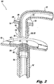
- Injector 100 includes a feed arm 102 extending from an inlet fitting 104 to a nozzle body 106 opposite the inlet fitting 104.
- the nozzle body 106 includes a spray outlet 108 in fluid communication with the inlet fitting 104 for issuing a spray of fluid supplied at the inlet fitting 104.
- the inlet fitting 104 of the feed arm 102 includes a receptacle 110 therein for receiving a fluid supply manifold 112 inside the inlet fitting 104 of the feed arm.
- the receptacle 110 includes internal threads 114 configured to be threaded to corresponding threads 116 for securing an outlet end 118 of fluid supply manifold 112 in the receptacle 110.
- a mounting flange 120 extends radially outward from the inlet fitting 104 of the feed arm 102 for mounting the feed arm 102 to a supporting structure 122, e.g., an engine case.
- the receptacle 110 and the internal threads 114 of the inlet fitting 104 are within the feed arm 102 between the mounting flange 120 and the nozzle body 106 (shown in Fig. 1 ) lengthwise along the feed arm 102.
- the receptacle 110 includes at least one seal for sealing against the outlet end 118 of the fuel supply manifold 112 in the receptacle 110.
- the receptacle 110 includes a flared seal surface 124.
- the outlet end of the fluid supply manifold defines an enlargement 128 with a corresponding flared sealing surface 126.
- the flared sealing surfaces 124 and 126 engage one another to seal fluid within the internal passage formed inside fluid supply manifold 112 and feed arm 102.
- Fig. 3 when fluid supply manifold 112 and feed arm 102 are assembled together, the flared sealing surfaces 124 and 126 engage one another to seal fluid within the internal passage formed inside fluid supply manifold 112 and feed arm 102.
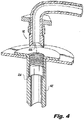
- the flare direction of the flaring of the sealing surface 124 can be reversed from radially inward to be radially outward facing, as is sealing surface 224 of feed arm 102 in Fig. 4 , and the corresponding sealing surface 226 of manifold 112 is flared in the opposite direction as well.
- the enlargement 128 of the outlet end 118 of the fuel supply manifold 112 defines a cylindrical, outward facing sealing surface 130 configured to seal against a corresponding sealing surface 132 in the receptacle 110 of feed arm 102.
- Any of surfaces 124, 224, 126, 226, 130, and 132 can include any suitable sealing features such as O-rings or the like to ensure proper sealing.
- a threaded nut 134 is disposed about the fluid supply manifold 112.
- the enlargement 128 of the outlet end 118 of the fluid supply manifold 112 is configured to prevent relative axial movement of the threaded nut 134 beyond the outlet end 118 of the fluid supply manifold 112.
- the external threads 116 of the threaded nut are proximate the enlargement 128 of the fluid supply manifold 112.
- the enlargement 128 of fluid supply manifold 112 is captive within receptacle 110 when the threads 114 and 116 are threaded together, thus securing the outlet end 118 of the fluid supply manifold 112 in the receptacle 110.
- the threaded nut 134 includes a flange 136 external from the receptacle 110 with engagement surfaces 138, e.g., arranged in a hexagon, configured to engage a tool, e.g., a hexagon wrench, for rotating the threaded nut 134 to engage or disengage the threads 116 in the receptacle 110 of the feed arm 102.
- the fluid supply manifold 112, threaded nut 134, and injector 100 form part of a fluid delivery assembly, optionally with additional similar injectors, manifold outlets, and threaded nuts, e.g., for supplying fuel form a source such as a fuel tank to a combustor of a gas turbine engine.
- a source such as a fuel tank to a combustor of a gas turbine engine.
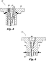
- FIG. 5 another embodiment of injector 200 is shown, wherein the receptacle 210, similar to receptacle 110 described above, is joined within feed arm 202, where the joints are indicated in Fig. 5 with the large arrows.
- FIG. 6 an exemplary example of an injector 300 including a receptacle 310, similar to receptacle 110 described above, is shown, wherein the receptacle 310 is integral with an upper portion 301 of feed arm 302, which is joined to the lower portion of feed arm 302 at a joint indicated by the large arrows in Fig. 6 .
- FIG. 7 shows another example of an injector 400 with a receptacle 401, similar to receptacle 110 described above, joined to the feed arm 402 at the joint indicated by the large arrows in Fig. 7 .
- injector 500 is shown, including a receptacle 510 much as those described above, wherein the receptacle is connected to the feed arm 502 by a flexure beam 507.
- the flexure beam is joined to the receptacle 510 and to the feed arm 502 at the joints indicated by large arrows in Fig. 8 .
- the different connection configurations shown in Figs. 5 to 8 may be suitable for different applications. For example, the joints in Figs.
- Fig. 8 are remote from the seal locations, and allow for thermal isolation between cool fluids delivered through the manifold and potentially extreme heat outside the feed arm.
- the example in Fig. 8 also allows for tolerance of high torque, if required for example to tighten a threaded nut such as described above.
- a receptacle in accordance with this disclosure can be formed integrally with a feed arm, e.g., by additive manufacturing, conventional machining or any other suitable process, as in Fig. 1 . It is also contemplated that a combination of integrally forming and brazing can be used, as in Fig. 6 , wherein receptacle 310 is connected to the feed arm by being integrally formed with upper portion 301, which is in turn joined to lower portion 303 of feed arm 302.
- the seal location can be along the faces that engage a manifold axially, as indicated in Fig. 5 by reference character 260, which can optionally be flared as described above with respect to Figs 2 and 3 .
- Surface 250 in Fig. 5 is threaded for engaging a manifold such as manifold 112 described above, and similar threads are included in Figs. 6 to 8 .
Landscapes
- Engineering & Computer Science (AREA)
- Chemical & Material Sciences (AREA)
- Combustion & Propulsion (AREA)
- Mechanical Engineering (AREA)
- General Engineering & Computer Science (AREA)
- Fuel-Injection Apparatus (AREA)
Applications Claiming Priority (1)
| Application Number | Priority Date | Filing Date | Title |
|---|---|---|---|
| US14/971,339 US10436448B2 (en) | 2015-12-16 | 2015-12-16 | Injector fittings |
Publications (2)
| Publication Number | Publication Date |
|---|---|
| EP3182014A1 true EP3182014A1 (fr) | 2017-06-21 |
| EP3182014B1 EP3182014B1 (fr) | 2019-10-30 |
Family
ID=57542757
Family Applications (1)
| Application Number | Title | Priority Date | Filing Date |
|---|---|---|---|
| EP16202593.6A Active EP3182014B1 (fr) | 2015-12-16 | 2016-12-07 | Raccords d'injecteur |
Country Status (2)
| Country | Link |
|---|---|
| US (1) | US10436448B2 (fr) |
| EP (1) | EP3182014B1 (fr) |
Families Citing this family (6)
| Publication number | Priority date | Publication date | Assignee | Title |
|---|---|---|---|---|
| JP6863718B2 (ja) * | 2016-11-21 | 2021-04-21 | 三菱パワー株式会社 | ガスタービン燃焼器 |
| US11111821B2 (en) | 2019-09-18 | 2021-09-07 | Raytheon Technologies Corporation | Retention assembly for gas turbine engine |
| US11466859B2 (en) * | 2020-12-18 | 2022-10-11 | Pratt & Whitney Canada Corp. | Gap filler for a fuel system gallery |
| US20230108259A1 (en) * | 2021-10-05 | 2023-04-06 | Delavan Inc. | Threaded joints for fluid injection components |
| US12209750B2 (en) * | 2023-02-14 | 2025-01-28 | Collins Engine Nozzles, Inc. | Line replaceable fuel injector panels with single hatch installation |
| US12480657B1 (en) * | 2025-04-29 | 2025-11-25 | General Electric Company | Gas turbine engine and fuel nozzle therefor |
Citations (6)
| Publication number | Priority date | Publication date | Assignee | Title |
|---|---|---|---|---|
| FR2227436A1 (fr) * | 1973-04-27 | 1974-11-22 | Snecma | |
| US5279112A (en) * | 1992-02-18 | 1994-01-18 | General Electric Company | Fuel line fitting |
| EP2719953A2 (fr) * | 2012-10-09 | 2014-04-16 | Delavan Inc. | Injecteurs multipoints à étage auxiliaire |
| WO2014137696A2 (fr) * | 2013-03-04 | 2014-09-12 | Siemens Aktiengesellschaft | Appareil de chambre de combustion dans un moteur à turbine à gaz |
| WO2014210402A1 (fr) * | 2013-06-27 | 2014-12-31 | Siemens Energy, Inc. | Appareil de combustion dans un moteur à turbine à gaz |
| WO2015012908A2 (fr) * | 2013-07-01 | 2015-01-29 | United Technologies Corporation | Buse à carburant à deux circuits et à raccord unique |
Family Cites Families (2)
| Publication number | Priority date | Publication date | Assignee | Title |
|---|---|---|---|---|
| CA2248736C (fr) | 1996-03-13 | 2007-03-27 | Parker-Hannifin Corporation | Buse a bouclier thermique interieur |
| US8196845B2 (en) * | 2007-09-17 | 2012-06-12 | Delavan Inc | Flexure seal for fuel injection nozzle |
-
2015
- 2015-12-16 US US14/971,339 patent/US10436448B2/en active Active
-
2016
- 2016-12-07 EP EP16202593.6A patent/EP3182014B1/fr active Active
Patent Citations (6)
| Publication number | Priority date | Publication date | Assignee | Title |
|---|---|---|---|---|
| FR2227436A1 (fr) * | 1973-04-27 | 1974-11-22 | Snecma | |
| US5279112A (en) * | 1992-02-18 | 1994-01-18 | General Electric Company | Fuel line fitting |
| EP2719953A2 (fr) * | 2012-10-09 | 2014-04-16 | Delavan Inc. | Injecteurs multipoints à étage auxiliaire |
| WO2014137696A2 (fr) * | 2013-03-04 | 2014-09-12 | Siemens Aktiengesellschaft | Appareil de chambre de combustion dans un moteur à turbine à gaz |
| WO2014210402A1 (fr) * | 2013-06-27 | 2014-12-31 | Siemens Energy, Inc. | Appareil de combustion dans un moteur à turbine à gaz |
| WO2015012908A2 (fr) * | 2013-07-01 | 2015-01-29 | United Technologies Corporation | Buse à carburant à deux circuits et à raccord unique |
Also Published As
| Publication number | Publication date |
|---|---|
| US20170176010A1 (en) | 2017-06-22 |
| US10436448B2 (en) | 2019-10-08 |
| EP3182014B1 (fr) | 2019-10-30 |
Similar Documents
| Publication | Publication Date | Title |
|---|---|---|
| EP3182014B1 (fr) | Raccords d'injecteur | |
| US8641099B2 (en) | Coupling with one-piece plural nipples | |
| US9506403B2 (en) | Fastener | |
| US5890746A (en) | Cooled and wetted redundant seal tube fitting | |
| US10371293B2 (en) | Movement-constraining assembly for fluid-conveying system | |
| EP3358140B1 (fr) | Raccord pour tube à parois multiples | |
| EP2902605A1 (fr) | Collecteur de carburant et dispositif d'injecteur de carburant pour turbine à gaz | |
| US10208723B2 (en) | Threaded fuel rails | |
| EP4063734B1 (fr) | Ensemble pour un moteur de turbine à gaz comprenant un injecteur de carburant | |
| US12123314B2 (en) | Service tube assembly for a gas turbine engine | |
| US9958093B2 (en) | Flexible hose assembly with multiple flow passages | |
| US9772054B2 (en) | Concentric flexible hose assembly | |
| JP6649677B2 (ja) | ガソリン直噴エンジン用燃料レール | |
| US9683690B2 (en) | Movement-constraining assembly for fluid-conveying system | |
| US11408540B2 (en) | Tube coupling assembly | |
| US10344624B2 (en) | Captive component on a fastener | |
| US10240793B2 (en) | Single-fitting, dual-circuit fuel nozzle | |
| CN114423928B (zh) | 用于对涡轮机的外壳体进行冷却的装置和设置有这种装置的涡轮机 | |
| KR101960201B1 (ko) | 가솔린 직분사 엔진용 연료 레일의 단말 시일 구조 | |
| US20100139279A1 (en) | Fuel delivery system and method of assembling the same | |
| US10119635B2 (en) | Locking fluid fittings | |
| EP3358237B1 (fr) | Raccord de tuyau | |
| US20180094816A1 (en) | Injector resonator for a gas turbine engine | |
| US20100148498A1 (en) | Swivel Misalignment Coupling for Connecting Conduit Sections | |
| WO2014052045A1 (fr) | Système de raccord amovible pour relier un flexible ou un tube à un tube d'enveloppement |
Legal Events
| Date | Code | Title | Description |
|---|---|---|---|
| PUAI | Public reference made under article 153(3) epc to a published international application that has entered the european phase |
Free format text: ORIGINAL CODE: 0009012 |
|
| STAA | Information on the status of an ep patent application or granted ep patent |
Free format text: STATUS: THE APPLICATION HAS BEEN PUBLISHED |
|
| AK | Designated contracting states |
Kind code of ref document: A1 Designated state(s): AL AT BE BG CH CY CZ DE DK EE ES FI FR GB GR HR HU IE IS IT LI LT LU LV MC MK MT NL NO PL PT RO RS SE SI SK SM TR |
|
| AX | Request for extension of the european patent |
Extension state: BA ME |
|
| STAA | Information on the status of an ep patent application or granted ep patent |
Free format text: STATUS: REQUEST FOR EXAMINATION WAS MADE |
|
| 17P | Request for examination filed |
Effective date: 20171221 |
|
| RBV | Designated contracting states (corrected) |
Designated state(s): AL AT BE BG CH CY CZ DE DK EE ES FI FR GB GR HR HU IE IS IT LI LT LU LV MC MK MT NL NO PL PT RO RS SE SI SK SM TR |
|
| RIN1 | Information on inventor provided before grant (corrected) |
Inventor name: CAPLES, MARK A Inventor name: PFEFFER, BRETT A. Inventor name: RYON, JASON A. Inventor name: BLEEKER, DANIEL E. |
|
| GRAP | Despatch of communication of intention to grant a patent |
Free format text: ORIGINAL CODE: EPIDOSNIGR1 |
|
| STAA | Information on the status of an ep patent application or granted ep patent |
Free format text: STATUS: GRANT OF PATENT IS INTENDED |
|
| RIC1 | Information provided on ipc code assigned before grant |
Ipc: F02C 7/22 20060101ALI20190410BHEP Ipc: F23R 3/28 20060101AFI20190410BHEP |
|
| INTG | Intention to grant announced |
Effective date: 20190506 |
|
| GRAS | Grant fee paid |
Free format text: ORIGINAL CODE: EPIDOSNIGR3 |
|
| GRAA | (expected) grant |
Free format text: ORIGINAL CODE: 0009210 |
|
| STAA | Information on the status of an ep patent application or granted ep patent |
Free format text: STATUS: THE PATENT HAS BEEN GRANTED |
|
| AK | Designated contracting states |
Kind code of ref document: B1 Designated state(s): AL AT BE BG CH CY CZ DE DK EE ES FI FR GB GR HR HU IE IS IT LI LT LU LV MC MK MT NL NO PL PT RO RS SE SI SK SM TR |
|
| REG | Reference to a national code |
Ref country code: GB Ref legal event code: FG4D |
|
| REG | Reference to a national code |
Ref country code: CH Ref legal event code: EP |
|
| REG | Reference to a national code |
Ref country code: AT Ref legal event code: REF Ref document number: 1196562 Country of ref document: AT Kind code of ref document: T Effective date: 20191115 |
|
| REG | Reference to a national code |
Ref country code: DE Ref legal event code: R096 Ref document number: 602016023241 Country of ref document: DE |
|
| REG | Reference to a national code |
Ref country code: IE Ref legal event code: FG4D |
|
| REG | Reference to a national code |
Ref country code: LT Ref legal event code: MG4D |
|
| PG25 | Lapsed in a contracting state [announced via postgrant information from national office to epo] |
Ref country code: NL Free format text: LAPSE BECAUSE OF FAILURE TO SUBMIT A TRANSLATION OF THE DESCRIPTION OR TO PAY THE FEE WITHIN THE PRESCRIBED TIME-LIMIT Effective date: 20191030 Ref country code: PT Free format text: LAPSE BECAUSE OF FAILURE TO SUBMIT A TRANSLATION OF THE DESCRIPTION OR TO PAY THE FEE WITHIN THE PRESCRIBED TIME-LIMIT Effective date: 20200302 Ref country code: LT Free format text: LAPSE BECAUSE OF FAILURE TO SUBMIT A TRANSLATION OF THE DESCRIPTION OR TO PAY THE FEE WITHIN THE PRESCRIBED TIME-LIMIT Effective date: 20191030 Ref country code: BG Free format text: LAPSE BECAUSE OF FAILURE TO SUBMIT A TRANSLATION OF THE DESCRIPTION OR TO PAY THE FEE WITHIN THE PRESCRIBED TIME-LIMIT Effective date: 20200130 Ref country code: FI Free format text: LAPSE BECAUSE OF FAILURE TO SUBMIT A TRANSLATION OF THE DESCRIPTION OR TO PAY THE FEE WITHIN THE PRESCRIBED TIME-LIMIT Effective date: 20191030 Ref country code: PL Free format text: LAPSE BECAUSE OF FAILURE TO SUBMIT A TRANSLATION OF THE DESCRIPTION OR TO PAY THE FEE WITHIN THE PRESCRIBED TIME-LIMIT Effective date: 20191030 Ref country code: SE Free format text: LAPSE BECAUSE OF FAILURE TO SUBMIT A TRANSLATION OF THE DESCRIPTION OR TO PAY THE FEE WITHIN THE PRESCRIBED TIME-LIMIT Effective date: 20191030 Ref country code: LV Free format text: LAPSE BECAUSE OF FAILURE TO SUBMIT A TRANSLATION OF THE DESCRIPTION OR TO PAY THE FEE WITHIN THE PRESCRIBED TIME-LIMIT Effective date: 20191030 Ref country code: GR Free format text: LAPSE BECAUSE OF FAILURE TO SUBMIT A TRANSLATION OF THE DESCRIPTION OR TO PAY THE FEE WITHIN THE PRESCRIBED TIME-LIMIT Effective date: 20200131 Ref country code: NO Free format text: LAPSE BECAUSE OF FAILURE TO SUBMIT A TRANSLATION OF THE DESCRIPTION OR TO PAY THE FEE WITHIN THE PRESCRIBED TIME-LIMIT Effective date: 20200130 |
|
| REG | Reference to a national code |
Ref country code: NL Ref legal event code: MP Effective date: 20191030 |
|
| PG25 | Lapsed in a contracting state [announced via postgrant information from national office to epo] |
Ref country code: HR Free format text: LAPSE BECAUSE OF FAILURE TO SUBMIT A TRANSLATION OF THE DESCRIPTION OR TO PAY THE FEE WITHIN THE PRESCRIBED TIME-LIMIT Effective date: 20191030 Ref country code: RS Free format text: LAPSE BECAUSE OF FAILURE TO SUBMIT A TRANSLATION OF THE DESCRIPTION OR TO PAY THE FEE WITHIN THE PRESCRIBED TIME-LIMIT Effective date: 20191030 Ref country code: IS Free format text: LAPSE BECAUSE OF FAILURE TO SUBMIT A TRANSLATION OF THE DESCRIPTION OR TO PAY THE FEE WITHIN THE PRESCRIBED TIME-LIMIT Effective date: 20200229 |
|
| PG25 | Lapsed in a contracting state [announced via postgrant information from national office to epo] |
Ref country code: AL Free format text: LAPSE BECAUSE OF FAILURE TO SUBMIT A TRANSLATION OF THE DESCRIPTION OR TO PAY THE FEE WITHIN THE PRESCRIBED TIME-LIMIT Effective date: 20191030 |
|
| PG25 | Lapsed in a contracting state [announced via postgrant information from national office to epo] |
Ref country code: CZ Free format text: LAPSE BECAUSE OF FAILURE TO SUBMIT A TRANSLATION OF THE DESCRIPTION OR TO PAY THE FEE WITHIN THE PRESCRIBED TIME-LIMIT Effective date: 20191030 Ref country code: RO Free format text: LAPSE BECAUSE OF FAILURE TO SUBMIT A TRANSLATION OF THE DESCRIPTION OR TO PAY THE FEE WITHIN THE PRESCRIBED TIME-LIMIT Effective date: 20191030 Ref country code: ES Free format text: LAPSE BECAUSE OF FAILURE TO SUBMIT A TRANSLATION OF THE DESCRIPTION OR TO PAY THE FEE WITHIN THE PRESCRIBED TIME-LIMIT Effective date: 20191030 Ref country code: EE Free format text: LAPSE BECAUSE OF FAILURE TO SUBMIT A TRANSLATION OF THE DESCRIPTION OR TO PAY THE FEE WITHIN THE PRESCRIBED TIME-LIMIT Effective date: 20191030 Ref country code: DK Free format text: LAPSE BECAUSE OF FAILURE TO SUBMIT A TRANSLATION OF THE DESCRIPTION OR TO PAY THE FEE WITHIN THE PRESCRIBED TIME-LIMIT Effective date: 20191030 |
|
| REG | Reference to a national code |
Ref country code: CH Ref legal event code: PL Ref country code: DE Ref legal event code: R097 Ref document number: 602016023241 Country of ref document: DE |
|
| REG | Reference to a national code |
Ref country code: AT Ref legal event code: MK05 Ref document number: 1196562 Country of ref document: AT Kind code of ref document: T Effective date: 20191030 |
|
| REG | Reference to a national code |
Ref country code: BE Ref legal event code: MM Effective date: 20191231 |
|
| PG25 | Lapsed in a contracting state [announced via postgrant information from national office to epo] |
Ref country code: SK Free format text: LAPSE BECAUSE OF FAILURE TO SUBMIT A TRANSLATION OF THE DESCRIPTION OR TO PAY THE FEE WITHIN THE PRESCRIBED TIME-LIMIT Effective date: 20191030 Ref country code: MC Free format text: LAPSE BECAUSE OF FAILURE TO SUBMIT A TRANSLATION OF THE DESCRIPTION OR TO PAY THE FEE WITHIN THE PRESCRIBED TIME-LIMIT Effective date: 20191030 Ref country code: SM Free format text: LAPSE BECAUSE OF FAILURE TO SUBMIT A TRANSLATION OF THE DESCRIPTION OR TO PAY THE FEE WITHIN THE PRESCRIBED TIME-LIMIT Effective date: 20191030 Ref country code: IT Free format text: LAPSE BECAUSE OF FAILURE TO SUBMIT A TRANSLATION OF THE DESCRIPTION OR TO PAY THE FEE WITHIN THE PRESCRIBED TIME-LIMIT Effective date: 20191030 |
|
| PLBE | No opposition filed within time limit |
Free format text: ORIGINAL CODE: 0009261 |
|
| STAA | Information on the status of an ep patent application or granted ep patent |
Free format text: STATUS: NO OPPOSITION FILED WITHIN TIME LIMIT |
|
| 26N | No opposition filed |
Effective date: 20200731 |
|
| PG25 | Lapsed in a contracting state [announced via postgrant information from national office to epo] |
Ref country code: LU Free format text: LAPSE BECAUSE OF NON-PAYMENT OF DUE FEES Effective date: 20191207 Ref country code: IE Free format text: LAPSE BECAUSE OF NON-PAYMENT OF DUE FEES Effective date: 20191207 |
|
| PG25 | Lapsed in a contracting state [announced via postgrant information from national office to epo] |
Ref country code: SI Free format text: LAPSE BECAUSE OF FAILURE TO SUBMIT A TRANSLATION OF THE DESCRIPTION OR TO PAY THE FEE WITHIN THE PRESCRIBED TIME-LIMIT Effective date: 20191030 Ref country code: BE Free format text: LAPSE BECAUSE OF NON-PAYMENT OF DUE FEES Effective date: 20191231 Ref country code: CH Free format text: LAPSE BECAUSE OF NON-PAYMENT OF DUE FEES Effective date: 20191231 Ref country code: LI Free format text: LAPSE BECAUSE OF NON-PAYMENT OF DUE FEES Effective date: 20191231 Ref country code: AT Free format text: LAPSE BECAUSE OF FAILURE TO SUBMIT A TRANSLATION OF THE DESCRIPTION OR TO PAY THE FEE WITHIN THE PRESCRIBED TIME-LIMIT Effective date: 20191030 |
|
| PG25 | Lapsed in a contracting state [announced via postgrant information from national office to epo] |
Ref country code: CY Free format text: LAPSE BECAUSE OF FAILURE TO SUBMIT A TRANSLATION OF THE DESCRIPTION OR TO PAY THE FEE WITHIN THE PRESCRIBED TIME-LIMIT Effective date: 20191030 |
|
| PG25 | Lapsed in a contracting state [announced via postgrant information from national office to epo] |
Ref country code: HU Free format text: LAPSE BECAUSE OF FAILURE TO SUBMIT A TRANSLATION OF THE DESCRIPTION OR TO PAY THE FEE WITHIN THE PRESCRIBED TIME-LIMIT; INVALID AB INITIO Effective date: 20161207 Ref country code: MT Free format text: LAPSE BECAUSE OF FAILURE TO SUBMIT A TRANSLATION OF THE DESCRIPTION OR TO PAY THE FEE WITHIN THE PRESCRIBED TIME-LIMIT Effective date: 20191030 |
|
| PG25 | Lapsed in a contracting state [announced via postgrant information from national office to epo] |
Ref country code: TR Free format text: LAPSE BECAUSE OF FAILURE TO SUBMIT A TRANSLATION OF THE DESCRIPTION OR TO PAY THE FEE WITHIN THE PRESCRIBED TIME-LIMIT Effective date: 20191030 |
|
| PG25 | Lapsed in a contracting state [announced via postgrant information from national office to epo] |
Ref country code: MK Free format text: LAPSE BECAUSE OF FAILURE TO SUBMIT A TRANSLATION OF THE DESCRIPTION OR TO PAY THE FEE WITHIN THE PRESCRIBED TIME-LIMIT Effective date: 20191030 |
|
| P01 | Opt-out of the competence of the unified patent court (upc) registered |
Effective date: 20230530 |
|
| PGFP | Annual fee paid to national office [announced via postgrant information from national office to epo] |
Ref country code: DE Payment date: 20251126 Year of fee payment: 10 |
|
| PGFP | Annual fee paid to national office [announced via postgrant information from national office to epo] |
Ref country code: GB Payment date: 20251120 Year of fee payment: 10 |
|
| PGFP | Annual fee paid to national office [announced via postgrant information from national office to epo] |
Ref country code: FR Payment date: 20251120 Year of fee payment: 10 |