EP3182015A1 - Chambre de combustion et turbine à gaz la comprenant - Google Patents
Chambre de combustion et turbine à gaz la comprenant Download PDFInfo
- Publication number
- EP3182015A1 EP3182015A1 EP15845017.1A EP15845017A EP3182015A1 EP 3182015 A1 EP3182015 A1 EP 3182015A1 EP 15845017 A EP15845017 A EP 15845017A EP 3182015 A1 EP3182015 A1 EP 3182015A1
- Authority
- EP
- European Patent Office
- Prior art keywords
- tapered surface
- burner
- cylinder
- plate thickness
- flow path
- Prior art date
- Legal status (The legal status is an assumption and is not a legal conclusion. Google has not performed a legal analysis and makes no representation as to the accuracy of the status listed.)
- Granted
Links
Images


Classifications
-
- F—MECHANICAL ENGINEERING; LIGHTING; HEATING; WEAPONS; BLASTING
- F23—COMBUSTION APPARATUS; COMBUSTION PROCESSES
- F23R—GENERATING COMBUSTION PRODUCTS OF HIGH PRESSURE OR HIGH VELOCITY, e.g. GAS-TURBINE COMBUSTION CHAMBERS
- F23R3/00—Continuous combustion chambers using liquid or gaseous fuel
- F23R3/02—Continuous combustion chambers using liquid or gaseous fuel characterised by the air-flow or gas-flow configuration
- F23R3/04—Air inlet arrangements
- F23R3/10—Air inlet arrangements for primary air
-
- F—MECHANICAL ENGINEERING; LIGHTING; HEATING; WEAPONS; BLASTING
- F02—COMBUSTION ENGINES; HOT-GAS OR COMBUSTION-PRODUCT ENGINE PLANTS
- F02C—GAS-TURBINE PLANTS; AIR INTAKES FOR JET-PROPULSION PLANTS; CONTROLLING FUEL SUPPLY IN AIR-BREATHING JET-PROPULSION PLANTS
- F02C3/00—Gas-turbine plants characterised by the use of combustion products as the working fluid
- F02C3/04—Gas-turbine plants characterised by the use of combustion products as the working fluid having a turbine driving a compressor
-
- F—MECHANICAL ENGINEERING; LIGHTING; HEATING; WEAPONS; BLASTING
- F23—COMBUSTION APPARATUS; COMBUSTION PROCESSES
- F23R—GENERATING COMBUSTION PRODUCTS OF HIGH PRESSURE OR HIGH VELOCITY, e.g. GAS-TURBINE COMBUSTION CHAMBERS
- F23R3/00—Continuous combustion chambers using liquid or gaseous fuel
- F23R3/02—Continuous combustion chambers using liquid or gaseous fuel characterised by the air-flow or gas-flow configuration
- F23R3/04—Air inlet arrangements
- F23R3/10—Air inlet arrangements for primary air
- F23R3/12—Air inlet arrangements for primary air inducing a vortex
- F23R3/14—Air inlet arrangements for primary air inducing a vortex by using swirl vanes
-
- F—MECHANICAL ENGINEERING; LIGHTING; HEATING; WEAPONS; BLASTING
- F23—COMBUSTION APPARATUS; COMBUSTION PROCESSES
- F23R—GENERATING COMBUSTION PRODUCTS OF HIGH PRESSURE OR HIGH VELOCITY, e.g. GAS-TURBINE COMBUSTION CHAMBERS
- F23R3/00—Continuous combustion chambers using liquid or gaseous fuel
- F23R3/28—Continuous combustion chambers using liquid or gaseous fuel characterised by the fuel supply
- F23R3/286—Continuous combustion chambers using liquid or gaseous fuel characterised by the fuel supply having fuel-air premixing devices
-
- F—MECHANICAL ENGINEERING; LIGHTING; HEATING; WEAPONS; BLASTING
- F23—COMBUSTION APPARATUS; COMBUSTION PROCESSES
- F23R—GENERATING COMBUSTION PRODUCTS OF HIGH PRESSURE OR HIGH VELOCITY, e.g. GAS-TURBINE COMBUSTION CHAMBERS
- F23R3/00—Continuous combustion chambers using liquid or gaseous fuel
- F23R3/28—Continuous combustion chambers using liquid or gaseous fuel characterised by the fuel supply
- F23R3/30—Continuous combustion chambers using liquid or gaseous fuel characterised by the fuel supply comprising fuel prevapourising devices
-
- F—MECHANICAL ENGINEERING; LIGHTING; HEATING; WEAPONS; BLASTING
- F05—INDEXING SCHEMES RELATING TO ENGINES OR PUMPS IN VARIOUS SUBCLASSES OF CLASSES F01-F04
- F05D—INDEXING SCHEME FOR ASPECTS RELATING TO NON-POSITIVE-DISPLACEMENT MACHINES OR ENGINES, GAS-TURBINES OR JET-PROPULSION PLANTS
- F05D2240/00—Components
- F05D2240/35—Combustors or associated equipment
-
- F—MECHANICAL ENGINEERING; LIGHTING; HEATING; WEAPONS; BLASTING
- F23—COMBUSTION APPARATUS; COMBUSTION PROCESSES
- F23R—GENERATING COMBUSTION PRODUCTS OF HIGH PRESSURE OR HIGH VELOCITY, e.g. GAS-TURBINE COMBUSTION CHAMBERS
- F23R3/00—Continuous combustion chambers using liquid or gaseous fuel
- F23R3/28—Continuous combustion chambers using liquid or gaseous fuel characterised by the fuel supply
- F23R3/34—Feeding into different combustion zones
- F23R3/343—Pilot flames, i.e. fuel nozzles or injectors using only a very small proportion of the total fuel to insure continuous combustion
Definitions
- the present invention relates to a combustor and a gas turbine comprising the same.
- a combustor disclosed in Patent Document 1 includes a nozzle, having a rod-shaped portion, that sprays fuel, and a cylinder, surrounding the outer circumference of the nozzle, that jets air and the fuel from the nozzle toward a downstream side.
- Patent Document 1 Japanese Unexamined Patent Application Publication No. 2005-315457A
- the fuel is burned in the combustor, and a combustion gas produced by that burning flows in the combustor.
- the combustor thus has multiple components present in a high-temperature environment. What is needed, therefore, is a way to extend the service life of a combustor including such components.
- an object of the present invention is to provide a combustor that can have an extended service life, as well as a gas turbine including such a combustor.
- a combustor includes:
- the tapered surface is formed in the downstream end portion of the burner cylinder, and thus it is difficult for a gas containing fuel flowing on an inner circumferential side of the burner cylinder and air flowing on the outer circumferential side of the burner cylinder to form vortices on a downstream side of a downstream end of the burner cylinder.
- the possibility of flames forming near the downstream end of the burner cylinder can be reduced.
- the tapered surface formation width of the tapered surface in the plate thickness direction is no less than half the plate thickness of the part of the burner cylinder-forming plate where the tapered surface is not formed, the gas containing the fuel and the air will substantially not form vortices on the downstream side of the downstream end of the burner cylinder; or, even if such vortices are formed, those vortices will be small.
- the tapered surface formation width of the tapered surface in the plate thickness direction is 60% of the plate thickness of the part of the burner cylinder-forming plate where the tapered surface is not formed, there is a possibility of the gas containing the fuel and the air forming small vortices on the downstream side of the downstream end of the burner cylinder.
- the tapered surface formation width of the tapered surface in the plate thickness direction is set to no less than half the plate thickness of the part of the burner cylinder-forming plate where the tapered surface is not formed.
- an outer tapered surface may be formed in the outer circumferential side of the burner cylinder as the tapered surface, and a tapered surface formation width of the outer tapered surface in the plate thickness direction may be no less than half the plate thickness of the part of the burner cylinder-forming plate where the tapered surface is not formed.
- the air flowing along the outer circumferential side of the burner cylinder flows along the outer tapered surface, and thus this air approaches the burner axis while flowing toward the downstream side.
- this combustor a situation in which the gas containing the fuel flowing along the inner circumferential side of the burner cylinder spreads out in radial directions relative to the burner axis can be suppressed.
- an outer tapered surface may be formed in the outer circumferential side of the burner cylinder and an inner tapered surface may be formed in an inner circumferential side of the burner cylinder, and a width obtained by combining the tapered surface formation width of the outer tapered surface in the plate thickness direction and a taper formation width of the inner tapered surface in the plate thickness direction may be no less than half the plate thickness of the part of the burner cylinder-forming plate where the tapered surface is not formed.
- the tapered surface is formed in the downstream end portion of the burner cylinder, and furthermore, the tapered surface formation width, in the plate thickness direction, of the tapered surface including the outer tapered surface and the inner tapered surface is no less than half the plate thickness of the part of the burner cylinder-forming plate where the tapered surface is not formed.
- the possibility of flames forming near the downstream end of the burner cylinder can be reduced.
- the tapered surface formation width of the outer tapered surface in the plate thickness direction may be greater than the taper formation width of the inner tapered surface in the plate thickness direction.
- an inner tapered surface may be formed in an inner circumferential side of the burner cylinder as the tapered surface, and a taper formation width of the inner tapered surface in the plate thickness direction may be no less than half the plate thickness of the part of the burner cylinder-forming plate where the tapered surface is not formed.
- the tapered surface is formed in the downstream end portion of the burner cylinder, and furthermore, the tapered surface formation width of the inner tapered surface in the plate thickness direction is no less than half the plate thickness of the part of the burner cylinder-forming plate where the inner tapered surface is not formed.
- the possibility of flames forming near the downstream end of the burner cylinder can be reduced.
- the combustor may include a plurality of burners, each having the nozzle and the burner cylinder.
- the burner axes of the plurality of burners may be parallel to each other; at least a first outer circumference portion that is a part of the outer circumference of the burner cylinder of a first burner that is one of the plurality of burners may face a part of an inner circumference of the outside flow path cylinder such that a first purge air flow path serving as the purge air flow path is formed between the first outer circumference portion and the part of the inner circumference of the outside flow path cylinder; a second purge air flow path in which air flows toward the downstream side may be formed between a part of an outer circumference of the burner cylinder of a second burner that, of the plurality of burners, is adjacent to the first burner, and a second outer circumference portion that is a part of the outer circumference of the burner cylinder of the first burner; and an angle of
- the angle of the tapered surface relative to the burner axis be small.
- the angle of the outer tapered surface in the second outer circumference portion relative to the burner axis is greater than the angle of the outer tapered surface in the first outer circumference portion relative to the burner axis.
- the second burner is adjacent to the second outer circumference portion of the first burner.
- the gas containing the fuel which has flowed along the inner circumferential side of the first burner cylinder, is floating near the downstream end of the part where the second outer circumference portion is formed in the downstream end portion of the first burner cylinder, it is possible that the fuel will ignite near that downstream end.
- the angle of the outer tapered surface formed in the second outer circumference portion relative to the burner axis is made greater than the angle of the outer tapered surface formed in the first outer circumference portion relative to the burner axis in order to ensure that the gas containing the fuel jetted from the first burner cylinder moves away from the adjacent second burner.
- the first burner may be a premixed combustion burner that burns fuel jetted from the burner cylinder of the first burner through premixed combustion;
- the second burner may be a diffusion combustion burner that burns fuel jetted from the burner cylinder of the second burner through diffusion combustion;
- a plurality of the first burners may be arranged in a circumferential direction centered on the second burner; and the outside flow path cylinder may have a cylindrical shape centered on the second burner so as to cover the plurality of first burners.
- a tapered surface may be formed in a downstream end portion of the outside flow path cylinder such that a plate thickness of an outside flow path cylinder-forming plate that forms the outside flow path cylinder gradually thins as the outside flow path cylinder-forming plate extends toward the downstream side, and a tapered surface formation width of the tapered surface in the plate thickness direction may be no less than half the plate thickness of the outside flow path cylinder-forming plate.
- a gas turbine includes:
- thermal damage and the like in a burner cylinder can be suppressed and the service life of a combustor can be extended.
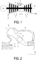
- a gas turbine includes a compressor 1 that generates compressed air by compressing outside air, a plurality of combustors 4 that generate a combustion gas by burning fuel F in the compressed air, and a turbine 5 driven by the combustion gas.
- the compressor 1 has a compressor rotor 2 that rotates about a rotational axis Ar and a compressor casing 3 that covers the compressor rotor 2 while allowing the compressor rotor 2 to rotate.
- the turbine 5 has a turbine rotor 6 that rotates about a rotational axis Ar and a turbine casing 7 that covers the turbine rotor 6 while allowing the turbine rotor 6 to rotate.
- the rotational axis Ar of the compressor rotor 2 and the rotational axis Ar of the turbine rotor 6 are located on the same straight line.
- the compressor rotor 2 and the turbine rotor 6 are connected with each other to form a gas turbine rotor 8. Meanwhile, the compressor casing 3 and the turbine casing 7 are connected with each other to form a gas turbine casing 9.
- a generator rotor for example, is connected to the gas turbine rotor 8. Furthermore, the combustors 4 are fixed to the gas turbine casing 9.
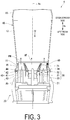
- each combustor 4 includes a combustion liner (or transition piece) 10 and a fuel jetting device 20.
- the fuel F is burned inside the combustion liner 10, and the combustion gas generated by burning the fuel F is guided to the turbine 5.
- the fuel jetting device 20 jets the fuel F and air A into the combustion liner 10.
- the fuel jetting device 20 includes: a pilot burner (second burner or diffusion combustion burner) 30 that burns the jetted fuel through diffusion combustion; main burners (first burners or premixed combustion burners) 40 that burn the jetted fuel through premixed combustion; and a burner holding cylinder 21 that holds the pilot burner 30 and the main burners 40.
- a pilot burner second burner or diffusion combustion burner
- main burners first burners or premixed combustion burners
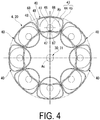
- the pilot burner 30 includes: a rod-shaped pilot nozzle 31 centered on a combustor axis Ac and extending in an axial direction Da; a pilot burner cylinder 33 that covers the outer circumference of the pilot nozzle 31; and a plurality of revolving plates 32 that cause the compressed air to swirl around the combustor axis Ac.
- one side in the axial direction Da which is the direction in which the combustor axis Ac extends, will be referred to as an upstream side, and the other side in the axial direction Da will be referred to as a downstream side.
- the combustor axis Ac is also a burner axis of the pilot burner 30.
- a spraying hole for spraying the fuel is formed in a downstream side end of the pilot nozzle 31.
- the plurality of revolving plates 32 are provided downstream from the location where the spraying hole is formed in the pilot nozzle 31.
- Each revolving plate 32 extends from the outer circumference of the pilot nozzle 31 in a direction including a radial direction component, and is connected to an inner circumferential surface of the pilot burner cylinder 33.
- the pilot burner cylinder 33 includes a main portion 34 located on the outer circumference of the pilot nozzle 31, and a cone portion 35 that is connected to a downstream side of the main portion 34 and gradually flares outward as the cone portion 35 extends in the downstream direction.
- the plurality of revolving plates 32 are connected to an inner circumferential surface of the main portion 34 in the pilot burner cylinder 33.
- the compressed air compressed by the compressor 1 flows into the pilot burner cylinder 33 from the upstream side thereof.
- the pilot burner cylinder 33 jets the fuel sprayed from the pilot nozzle 31, along with the compressed air, from a downstream end thereof. This fuel is burned in the combustion liner 10 through diffusion combustion.
- the plurality of main burners 40 are arranged in a circumferential direction, centered on to the combustor axis Ac, so as to surround the outer circumferential side of the pilot burner 30.
- each main burner 40 includes: a rod-shaped main nozzle 41, centered on a burner axis Ab parallel to the combustor axis Ac, and extending in the axial direction Da; a main burner cylinder 43 that covers the outer circumference of the main nozzle 41; and a plurality of revolving plates 42 that cause the compressed air to swirl around the burner axis Ab. Because the burner axis Ab of the main burner 40 is parallel to the combustor axis Ac, the axial direction Da relative to the combustor axis Ac is the same direction as the axial direction Da relative to the burner axis Ab.
- the upstream side in the axial direction Da relative to the combustor axis Ac corresponds to the upstream side in the axial direction Da relative to the burner axis Ab
- the downstream side in the axial direction Da relative to the combustor axis Ac corresponds to the downstream side in the axial direction Da relative to the burner axis Ab.
- a spraying hole for spraying the fuel is formed in a part midway along the main nozzle 41 in the axial direction Da.
- the plurality of revolving plates 42 are provided near the location where the spraying hole is formed in the main nozzle 41.
- Each revolving plate 42 extends from the outer circumference of the main nozzle 41 in a direction including a radial direction component, and is connected to an inner circumferential surface of the main burner cylinder 43.
- the main burner cylinder 43 includes a main portion 44 located on the outer circumference of the main nozzle 41, and an extended portion 45 that is connected to a downstream side of the main portion 44 and extends in the downstream direction.
- the plurality of revolving plates 42 are connected to an inner circumferential surface of the main portion 44 in the main burner cylinder 43.
- the compressed air compressed by the compressor 1 flows into the main burner cylinder 43 from the upstream side thereof.
- the main burner cylinder 43 jets the premixed gas PM from the downstream end thereof.
- the fuel in the premixed gas PM is burned through premixed combustion in the combustion liner 10.
- a spraying hole for spraying the fuel may be formed in the revolving plates 42, and the fuel may be sprayed into the main burner cylinder 43 from this spraying hole.
- the part corresponding to the rod-shaped main nozzle 41 described above constitutes a hub rod, and the main nozzle is formed including this hub rod and the plurality of revolving plates 42. Fuel is supplied into the hub rod from the exterior, and the fuel is supplied from the hub rod to the revolving plates 42.
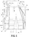
- the main portion 44 of the main burner cylinder 43 has a circular shape when viewed from the axial direction Da.
- the extended portion 45 of the main burner cylinder 43 has an arch shape formed by a large circular arc centered on the combustor axis Ac, a small circular arc located further toward the combustor axis Ac than the large circular arc and centered on the combustor axis Ac, and connection lines extending in a radial direction relative to the combustor axis Ac and linearly connecting ends of the large circular arc to corresponding ends of the small circular arc.
- a portion corresponding to the large circular arc constitutes a first outer circumference portion 46
- a portion corresponding to the small circular arc constitutes a second outer circumference portion 47
- portions corresponding to the connection lines constitute third outer circumference portions 48.
- the burner holding cylinder 21 has a cylindrical shape centered on the combustor axis Ac and covers the outer circumferential side of the main portions 44 of the plurality of main burner cylinders 43.
- the combustion liner 10 includes: a connecting portion 11 on an inner circumferential side of which the extended portions 45 of the plurality of main burner cylinders 43 are located; a combustion portion 13 forming a fuel region in which the fuel jetted from the main burners 40 and the pilot burner 30 is burned; and a combustion gas guide portion 15 that guides the combustion gas generated by burning the fuel to the turbine 5.
- Both the connecting portion 11 and the combustion portion 13 have a cylindrical shape centered on the combustor axis Ac.
- the combustion gas guide portion 15 has a tubular shape.
- An upstream end of the connecting portion 11 of the combustion liner 10 is connected to the burner holding cylinder 21.
- the combustion portion 13 of the combustion liner 10 is formed on the downstream side of the connecting portion 11 of the combustion liner 10.
- the combustion gas guide portion 15 of the combustion liner 10 is formed on the downstream side of the combustion portion 13 of the combustion liner 10.
- a connecting portion air hole 12 is formed in the cylindrical connecting portion 11 passing therethrough from the outer circumferential side to the inner circumferential side, so as to guide the compressed air from the compressor 1 as first purge air A1 to the inner circumferential side.
- An outside flow path cylinder 60 is disposed in the vicinity of a boundary between the connecting portion 11 and the combustion portion 13 of the combustion liner 10, the outside flow path cylinder 60 forming a first purge air flow path 66 between the outer circumferential sides of the plurality of main burners 40 and the inner circumferential side of the outside flow path cylinder 60 on the inner circumferential side of that boundary.
- the outside flow path cylinder 60 includes a cylindrical main portion 61 centered on the combustor axis Ac and a connecting portion 62 extending from a downstream side of the main portion 61 toward the outer circumferential side and connected to the combustion liner 10.
- a film air hole 14 is formed in a part of the combustion liner 10 opposing the main portion 61 of the outside flow path cylinder 60, passing through the combustion liner 10 from the outer circumferential side to the inner circumferential side, so as to guide the compressed air from the compressor 1 as film air A4 to the inner circumferential side.
- the aforementioned first purge air flow path 66 in which the first purge air A1 flows from the upstream side to the downstream side, is formed between the inner circumferential side of the main portion 61 of the outside flow path cylinder 60 and the first outer circumference portions 46 of the extended portions 45 of the plurality of main burner cylinders 43.
- a second purge air flow path 67 in which second purge air A2 flows from the upstream side to the downstream side, is formed between the second outer circumference portions 47 of the extended portions 45 of the plurality of main burner cylinders 43 and the outer circumference of the cone portion 35 of the pilot burner cylinder 33.
- a third purge air flow path 68 through which third purge air flows from the upstream side to the downstream side is formed between the third outer circumference portions 48 of the extended portions 45 of the main burner cylinders 43 adjacent to each other in a circumferential direction centered on the combustor axis Ac.
- the third purge air and the aforementioned second purge air A2 are both compressed air that has been compressed by the compressor 1 and has flowed into the inner circumferential side of the burner holding cylinder 21.
- a tapered surface 50 is formed in the downstream end portion of the main burner cylinder 43 such that the plate thickness of a burner cylinder-forming plate 49 that forms the main burner cylinder 43 gradually thins as the burner cylinder-forming plate 49 extends toward the downstream side.
- This tapered surface 50 is an outer tapered surface 51, formed in the outer circumferential side of the main burner cylinder 43, that slopes so as to gradually approach the inner circumferential surface of the main burner cylinder 43 as the outer tapered surface extends toward the downstream side.
- the outer tapered surface 51 is formed across the entire outer circumference of the main burner cylinder 43.
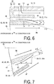
- the outer tapered surface 51 includes an outer tapered surface 51a formed in the first outer circumference portion 46 of the main burner cylinder 43, as illustrated in FIG. 6 , and an outer tapered surface 51b formed in the second outer circumference portion 47 of the main burner cylinder 43, as illustrated in FIG. 7 .
- the outer tapered surface 51 also includes an outer tapered surface (not illustrated) formed in the third outer circumference surface of the main burner cylinder 43.
- a tapered surface formation width t1 of the outer tapered surface 51a formed in the first outer circumference portion 46, in a plate thickness direction is no less than half a plate thickness t of a part of the burner cylinder-forming plate 49 where the outer tapered surface 51a is not formed. More preferably, the tapered surface formation width t1 of the outer tapered surface 51a formed in the first outer circumference portion 46, in the plate thickness direction, is no less than 60% of the plate thickness t of the part of the burner cylinder-forming plate 49 where the outer tapered surface 51a is not formed.
- the plate thickness t serving as a reference is the plate thickness of a furthest downstream part in the part of the burner cylinder-forming plate 49 where the outer tapered surface 51a is not formed.
- a tapered surface formation length s1 of the outer tapered surface 51a formed in the first outer circumference portion 46, in the axial direction Da, is longer than the aforementioned tapered surface formation width t1.
- An angle ⁇ 1 of the outer tapered surface 51a formed in the first outer circumference portion 46 relative to the burner axis Ab is no greater than 50° and no less than 20° (50° ⁇ ⁇ 1 ⁇ 20°).
- the inner circumferential surface and the outer circumferential surface of the burner cylinder-forming plate 49 at the part thereof where the first outer circumference portion 46 is formed are both parallel to the burner axis Ab. Accordingly, the angles of the outer tapered surface 51a relative to the inner circumferential surface and the outer circumferential surface of the burner cylinder-forming plate 49 at the outer tapered surface 51a are also no greater than 50° and no less than 20°.
- the angle ⁇ 1 of the outer tapered surface 51a relative to the burner axis Ab is an angle in a virtual plane that contains the burner axis Ab and intersects with the outer tapered surface 51a.
- the angles of the tapered surface 50 relative to the burner axis Ab are angles in a virtual plane that contains the burner axis Ab and intersects with the tapered surface 50.
- a tapered surface formation width t2 of the outer tapered surface 51b formed in the second outer circumference portion 47, in the plate thickness direction is no less than half the plate thickness t of a part of the burner cylinder-forming plate 49 where the outer tapered surface 51b is not formed. More preferably, the tapered surface formation width t2 of the outer tapered surface 51b formed in the second outer circumference portion 47, in the plate thickness direction, is no less than 60% of the plate thickness t of the part of the burner cylinder-forming plate 49 where the outer tapered surface 51b is not formed.
- a tapered surface formation length s2 of the outer tapered surface 51b formed in the second outer circumference portion 47, in the axial direction Da is no less than the aforementioned tapered surface formation width t2.
- the tapered surface formation length s2 of the outer tapered surface 51b formed in the second outer circumference portion 47, in the axial direction Da is the same length as the tapered surface formation length s1 of the outer tapered surface 51a formed in the first outer circumference portion 46, in the axial direction Da.
- An angle ⁇ 2 of the outer tapered surface 51b formed in the second outer circumference portion 47 relative to the burner axis Ab is greater than the angle ⁇ 1 of the outer tapered surface 51a formed in the first outer circumference portion 46 relative to the burner axis Ab.
- the angle ⁇ 2 is no greater than 70° and no less than 30° (70° ⁇ ⁇ 2 ⁇ 30°).
- a tapered surface formation width of the outer tapered surface 51 formed in the third outer circumference portion 48, in a plate thickness direction is also no less than half the plate thickness t of the part of the burner cylinder-forming plate 49 where the outer tapered surface 51 is not formed. More preferably, the tapered surface formation width of the outer tapered surface 51 formed in the third outer circumference portion 48, in the plate thickness direction, is also no less than 60% of the plate thickness t of the part of the burner cylinder-forming plate 49 where the outer tapered surface 51 is not formed.
- the angle of the outer tapered surface 51 formed in the third outer circumference portion 48 relative to the burner axis Ab is no greater than 50° and no less than 20°.
- a downstream end surface 45x of the main burner cylinder 43x is a flat surface perpendicular to the inner circumferential surface and the outer circumferential surface of the main burner cylinder 43x.
- the premixed gas PM flowing from the main burner cylinder 43x forms a vortex
- the first purge air A1 flowing from the first purge air flow path 66 formed on the outer circumferential side of the first outer circumference portion 46 of the main burner cylinder 43x forms a vortex.
- the premixed gas PM and the first purge air A1 form vortices on the downstream side of the downstream end surface 45x of the main burner cylinder 43x in this manner, there is an increased possibility of flames forming near the downstream end surface 45x of the main burner cylinder 43x.
- flames may form near the downstream end surface 45x of the main burner cylinder 43x depending on the operating state of the combustor.
- the downstream end portion of the main burner cylinder 43x will be put in a high-temperature environment, which subjects the main burner cylinder 43x to thermal damage and shortens the service life of the main burner cylinder 43x.
- the outer tapered surface 51 is formed across the entire outer circumference of the main burner cylinder 43 in the downstream end portion of the main burner cylinder 43 as described earlier.
- the possibility of flames forming near the downstream end of the main burner cylinder 43 can be reduced.
- thermal damage and the like in the main burner cylinder 43 can be suppressed and the service life of the main burner cylinder 43 can be extended more than is possible with the comparative example.
- the premixed gas PM and the first purge air A1 will substantially not form vortices on the downstream side of the downstream end of the main burner cylinder 43; or, even if such vortices are formed, those vortices will be small.
- the tapered surface formation width of the tapered surface 50 in the plate thickness direction is 60% of the plate thickness t of the part of the burner cylinder-forming plate 49 where the tapered surface 50 is not formed
- the premixed gas PM and the first purge air A1 forming small vortices on the downstream side of the downstream end of the main burner cylinder 43.
- the tapered surface formation width of the tapered surface 50 in the plate thickness direction is set to no less than half the plate thickness t of the part of the burner cylinder-forming plate 49 where the tapered surface 50 is not formed.
- the outer tapered surface 51 which is formed in the outer circumferential side of the main burner cylinder 43 and slopes so as to gradually approach the inner circumferential surface of the main burner cylinder 43 as the outer tapered surface extends toward the downstream side, is employed as the tapered surface 50.
- the angle of the tapered surface 50 relative to the burner axis Ab be small.
- the angle ⁇ 2 of the outer tapered surface 51b formed in the second outer circumference portion 47 relative to the burner axis Ab is greater than the angle ⁇ 1 of the outer tapered surface 51a formed in the first outer circumference portion 46 relative to the burner axis Ab.
- the pilot burner 30, which jets a gas AF in which fuel and air are not premixed and forms a diffusion flame, is disposed on the side toward the combustor axis Ac of the second outer circumference portion 47 of the main burner cylinder 43. Accordingly, if the premixed gas PM is floating near the downstream end of the part where the second outer circumference portion 47 is formed in the downstream end portion of the main burner cylinder 43, it is possible that the premixed gas PM will ignite near that downstream end.
- the angle ⁇ 2 of the outer tapered surface 51b formed in the second outer circumference portion 47 relative to the burner axis Ab is made greater than the angle ⁇ 1 of the outer tapered surface 51a formed in the first outer circumference portion 46 relative to the burner axis Ab in order to ensure that the premixed gas PM jetted from the main burner cylinder 43 moves away from the pilot burner 30.
- other main burners 40 are disposed on the circumferential direction sides of the third outer circumference portions 48 of the main burner cylinders 43 (that is, the circumferential direction centered on the combustor axis Ac).
- the angle of the outer tapered surface 51 formed in the third outer circumference portion 48 relative to the burner axis Ab be greater than the angle ⁇ 1 of the outer tapered surface 51a formed in the first outer circumference portion 46 relative to the burner axis Ab.
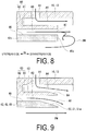
- FIG. 9 A first modified example of the combustor according to the embodiment described above will be described using FIG. 9 .
- the combustor according to the present modified example has the same configuration as the combustor according to the embodiment described above, except that a tapered surface is formed in the downstream end portion of the outside flow path cylinder 60 of the combustor according to the embodiment described above.
- the tapered surface of the outside flow path cylinder 60 is an outer tapered surface 64, formed in the outer circumferential side of the outside flow path cylinder 60, that slopes so as to gradually approach the inner circumferential surface of the outside flow path cylinder 60 as the outer tapered surface extends toward the downstream side.
- the tapered surface formation width of the outer tapered surface 64 in the plate thickness direction is no less than half the plate thickness of a part of an outside flow path cylinder-forming plate 63, which forms the main portion 61 of the outside flow path cylinder 60, where the outer tapered surface 64 is not formed.
- the present modified example it is difficult for the first purge air A1 flowing along the inner circumferential side of the outside flow path cylinder 60 and the film air A4 flowing along the outer circumferential side of the outside flow path cylinder 60 to form vortices on the downstream side of the downstream end of the outside flow path cylinder 60. As such, according to the present modified example, resistance to the flow of these airs can be suppressed.
- the outer tapered surface 64 is formed in the outer circumferential side of the outside flow path cylinder 60 as the tapered surface.
- the flow of the film air A4 and the first purge air A1 shifts slightly toward the combustor axis Ac (see FIG. 3 ), or in other words, moves away from the inner circumferential surface of the combustion liner 10, as those airs flow downstream.
- the premixed gas PM jetted from the main burner cylinder 43 the premixed gas PM flowing on the outside flow path cylinder 60 side shifts toward the combustor axis Ac as that gas flows downstream.
- thermal damage and the like at the downstream end of the main burner cylinder 43, at the downstream end of the part thereof where the first outer circumference portion 46 is formed, can be further suppressed, and thermal damage and the like to the inner circumferential surface of the combustion liner 10 can be further suppressed as well.
- FIG. 10 A second modified example of the combustor according to the embodiment described above will be described using FIG. 10 .
- the combustor according to the present modified example is also obtained by forming a tapered surface in the downstream end portion of the outside flow path cylinder 60 of the combustor according to the embodiment described above.
- the tapered surface of the outside flow path cylinder 60 according to the present modified example is an inner tapered surface 65, formed in the inner circumferential side of the outside flow path cylinder 60, that slopes so as to gradually approach the outer circumferential surface of the outside flow path cylinder 60 as the inner tapered surface extends toward the downstream side.
- the tapered surface formation width of the inner tapered surface 65 in the plate thickness direction is no less than half the plate thickness of a part of the outside flow path cylinder-forming plate 63, which forms the main portion 61 of the outside flow path cylinder 60, where the inner tapered surface 65 is not formed.
- the present modified example it is difficult for the first purge air A1 flowing along the inner circumferential side of the outside flow path cylinder 60 and the film air A4 flowing along the outer circumferential side of the outside flow path cylinder 60 to form vortices on the downstream side of the downstream end of the outside flow path cylinder 60. As such, according to the present modified example, resistance to the flow of these airs can be suppressed.
- the inner tapered surface 65 is formed in the inner circumferential side of the outside flow path cylinder 60 as the tapered surface.
- the flow the film air A4 and some of the first purge air A1 moves slightly away from the combustor axis Ac (see FIG. 3 ), or in other words, shifts toward the inner circumferential surface of the combustion liner 10, as those airs flow downstream.
- the film air A4 flows along the inner circumferential surface of the combustion liner 10 more than in the above-described embodiment and first modified example, which makes it possible to enhance a film cooling effect in the combustion liner 10.
- FIG. 11 A third modified example of the combustor according to the embodiment described above will be described using FIG. 11 .
- an outer tapered surface 51c and an inner tapered surface 52 are formed in the downstream end portion of the main burner cylinder 43.
- the outer tapered surface 51c is a surface, formed in the outer circumferential side of the main burner cylinder 43, that slopes so as to gradually approach the inner circumferential surface of the main burner cylinder 43 as the outer tapered surface extends toward the downstream side.
- the inner tapered surface 52 is a surface, formed in the inner circumferential side of the main burner cylinder 43, that slopes so as to gradually approach the outer circumferential surface of the main burner cylinder 43 as the inner tapered surface extends toward the downstream side.
- a width obtained by combining a tapered surface formation width t3 of the outer tapered surface 51c in the plate thickness direction and a tapered surface formation width t4 of the inner tapered surface 52 in the plate thickness direction is no less than half the plate thickness t of a part of the burner cylinder-forming plate 49 where the outer tapered surface 51c and the inner tapered surface 52 are not formed.
- a width of the tapered surface 50, which includes the outer tapered surface 51 c and the inner tapered surface 52, in the plate thickness direction is no less than half the plate thickness t of a part where the tapered surface 50 is not formed.
- a tapered surface formation width of the tapered surface 50 including the outer tapered surface 51c and the inner tapered surface 52, in the plate thickness direction is no less than 60% of the plate thickness t of the part of the burner cylinder-forming plate 49 where the tapered surface 50 is not formed. Additionally, the tapered surface formation width t3 of the outer tapered surface 51c in the plate thickness direction is greater than the taper formation width t4 of the inner tapered surface 52 in the plate thickness direction.
- an angle ⁇ 1 of the outer tapered surface 51c relative to the burner axis Ab is no greater than 50° and no less than 20° (50° ⁇ ⁇ 1 ⁇ 20°).
- an angle ⁇ 3 of the inner tapered surface 52 relative to the burner axis Ab is also no greater than 50° and no less than 20° (50° ⁇ ⁇ 3 ⁇ 20°).
- each angle of a surface relative to the axis is one of two angles in a supplementary angle relationship. In this application, the smaller of the two angles in a supplementary angle relationship is taken as the angle of the tapered surface 50 relative to the axis.
- the angle ⁇ 1 of the outer tapered surface 51c relative to the burner axis Ab and the angle ⁇ 3 of the inner tapered surface 52 relative to the burner axis Ab need not be the same angle.
- a width of the tapered surface 50 which is a combination of the outer tapered surface 51c and the inner tapered surface 52, in the plate thickness direction, is no less than half the plate thickness t of a part where the tapered surface 50 is not formed, as in the above-described embodiment and modified examples. Accordingly, the premixed gas PM and the first purge air A1 will substantially not form vortices on the downstream side of the downstream end of the main burner cylinder 43, or even if such vortices are formed, those vortices will be small. Thus, according to the present modified example as well, thermal damage and the like in the main burner cylinder 43 can be suppressed and the service life of the main burner cylinder 43 can be extended.
- the tapered surface formation width t3 of the outer tapered surface 51c in the plate thickness direction is greater than the taper formation width t4 of the inner tapered surface 52 in the plate thickness direction. Accordingly, on the downstream side of the downstream end of the main burner cylinder 43, the flow of the first purge air A1 flowing along the outer tapered surface 51c has greater influence than the flow of the premixed gas PM flowing along the inner tapered surface 52, and thus a situation where the premixed gas PM jetted from the main burner cylinder 43 spreads out in radial directions relative to the burner axis Ab can be suppressed.
- FIG. 12 A fourth modified example of the combustor according to the embodiment described above will be described using FIG. 12 .
- an inner tapered surface 52a is formed in the downstream end portion of the main burner cylinder 43.
- the inner tapered surface 52a is a surface, formed in the inner circumferential side of the main burner cylinder 43, that slopes so as to gradually approach the outer circumferential surface of the main burner cylinder 43 as the inner tapered surface extends toward the downstream side.
- a tapered surface formation width t5 of the inner tapered surface 52a in the plate thickness direction is no less than half the plate thickness t of a part of the burner cylinder-forming plate 49 where the inner tapered surface 52a is not formed. More preferably, the tapered surface formation width t5 of the inner tapered surface 52a in the plate thickness direction is no less than 60% of the plate thickness t of the part of the burner cylinder-forming plate 49 where the inner tapered surface 52a is not formed.
- An angle ⁇ 3 of the inner tapered surface 52a relative to the burner axis Ab is no greater than 50° and no less than 20° (50° ⁇ ⁇ 3 ⁇ 20°).
- the width t5 of the inner tapered surface 52a in the plate thickness direction is no less than half the plate thickness t of the part where the inner tapered surface 52a is not formed, as described above. Accordingly, the premixed gas PM and the first purge air A1 will substantially not form vortices on the downstream side of the downstream end of the main burner cylinder 43, or even if such vortices are formed, those vortices will be small. Thus, according to the present modified example as well, thermal damage and the like in the main burner cylinder 43 can be suppressed and the service life of the main burner cylinder 43 can be extended.
- the inner tapered surface 52a is formed as the tapered surface 50, and thus unlike the above-described embodiment and modified examples, the premixed gas PM jetted from the main burner cylinder 43 tends to spread out in radial directions relative to the burner axis Ab.
- the present modified example may be employed in a case where thermal damage to the inner circumferential surface of the combustion liner 10 can be suppressed even if the premixed gas PM jetted from the main burner cylinder 43 spreads out slightly in radial directions relative to the burner axis Ab, such as in a case where a sufficient effect of cooling such as film cooling can be anticipated for the inner circumferential surface of the combustion liner 10, or a case where there is a long distance from the main burners 40 to the inner circumferential surface of a combustor basket in radial directions centered on the combustor axis Ac (see FIG. 3 ).
- FIG. 13 A fifth modified example of the combustor according to the embodiment described above will be described using FIG. 13 .
- the tapered surfaces have shapes that are straight lines on a virtual plane that contains the axis and intersects with the tapered surfaces.
- the tapered surface may have a shape that is a curve on the virtual plane that contains the axis and intersects with the tapered surface.
- an outer tapered surface 51d formed in a downstream end portion of the main burner cylinder 43 is a smooth curved surface, convex in a direction away from the burner axis Ab, on a virtual plane that contains the burner axis Ab and intersects with the outer tapered surface 51 d.
- This curved surface may be a smooth curved surface that is concave in a direction toward the burner axis Ab.
- FIG. 13 illustrates an example pertaining to the outer tapered surface 51d formed in the downstream end portion of the main burner cylinder 43.
- the inner tapered surface formed in the downstream end portion of the main burner cylinder 43, the tapered surface formed in the outside flow path cylinder 60, and so on may each have a shape that is a curve on the virtual plane that contains the axis and intersects with the tapered surface.
- an average angle of the tapered surface relative to the axis or an angle of a line connecting an upstream end and a downstream end of the tapered surface relative to the axis is used as the angle of the tapered surface relative to the axis.
- thermal damage and the like in a burner cylinder can be suppressed and the service life of a combustor can be extended.
Landscapes
- Engineering & Computer Science (AREA)
- Chemical & Material Sciences (AREA)
- Combustion & Propulsion (AREA)
- Mechanical Engineering (AREA)
- General Engineering & Computer Science (AREA)
- Gas Burners (AREA)
- Pre-Mixing And Non-Premixing Gas Burner (AREA)
Applications Claiming Priority (2)
| Application Number | Priority Date | Filing Date | Title |
|---|---|---|---|
| JP2014192498A JP6413196B2 (ja) | 2014-09-22 | 2014-09-22 | 燃焼器、及びこれを備えているガスタービン |
| PCT/JP2015/074833 WO2016047393A1 (fr) | 2014-09-22 | 2015-09-01 | Chambre de combustion et turbine à gaz la comprenant |
Publications (3)
| Publication Number | Publication Date |
|---|---|
| EP3182015A1 true EP3182015A1 (fr) | 2017-06-21 |
| EP3182015A4 EP3182015A4 (fr) | 2017-09-13 |
| EP3182015B1 EP3182015B1 (fr) | 2021-02-17 |
Family
ID=55580921
Family Applications (1)
| Application Number | Title | Priority Date | Filing Date |
|---|---|---|---|
| EP15845017.1A Active EP3182015B1 (fr) | 2014-09-22 | 2015-09-01 | Chambre de combustion et turbine à gaz la comprenant |
Country Status (7)
| Country | Link |
|---|---|
| US (1) | US11137141B2 (fr) |
| EP (1) | EP3182015B1 (fr) |
| JP (1) | JP6413196B2 (fr) |
| KR (1) | KR101898402B1 (fr) |
| CN (1) | CN106716016B (fr) |
| TW (1) | TWI588349B (fr) |
| WO (1) | WO2016047393A1 (fr) |
Families Citing this family (6)
| Publication number | Priority date | Publication date | Assignee | Title |
|---|---|---|---|---|
| CN107477612B (zh) * | 2017-07-20 | 2019-09-24 | 中国科学院工程热物理研究所 | 燃烧器 |
| RU201414U1 (ru) * | 2020-02-21 | 2020-12-14 | Акционерное общество "Управление отходами" | Топка выносная для получения газообразного теплоносителя сжиганием газообразного топлива |
| DE112021003888B4 (de) | 2020-10-07 | 2026-01-22 | Mitsubishi Heavy Industries, Ltd. | Gasturbinenbrennkammer und gasturbine |
| US12359813B2 (en) * | 2021-12-29 | 2025-07-15 | General Electric Company | Engine fuel nozzle and swirler |
| KR20250171352A (ko) * | 2023-06-13 | 2025-12-08 | 미츠비시 파워 가부시키가이샤 | 가스 터빈 연소기 및 가스 터빈 |
| US12571539B2 (en) | 2023-12-08 | 2026-03-10 | General Electric Company | Turbine engine having a combustion section with a fuel nozzle |
Family Cites Families (18)
| Publication number | Priority date | Publication date | Assignee | Title |
|---|---|---|---|---|
| GB1421399A (en) * | 1972-11-13 | 1976-01-14 | Snecma | Fuel injectors |
| JP3427617B2 (ja) | 1996-05-29 | 2003-07-22 | 株式会社日立製作所 | ガスタービン燃焼器 |
| WO1998025084A1 (fr) | 1996-12-04 | 1998-06-11 | Siemens Westinghouse Power Corporation | VEILLEUSE DE DIFFUSION A PREMELANGE POUR BRULEUR A FAIBLE DEGAGEMENT DE NOx |
| JP3337427B2 (ja) * | 1998-09-17 | 2002-10-21 | 三菱重工業株式会社 | ガスタービン用燃焼器 |
| JP2000314526A (ja) * | 1999-04-28 | 2000-11-14 | Ishikawajima Harima Heavy Ind Co Ltd | ガスタービン燃焼器の予蒸発予混合バーナおよび予混合バーナ |
| US6367262B1 (en) * | 2000-09-29 | 2002-04-09 | General Electric Company | Multiple annular swirler |
| JP2002276943A (ja) * | 2001-03-14 | 2002-09-25 | Mitsubishi Heavy Ind Ltd | ガスタービン用燃料ノズル |
| JP3826196B2 (ja) * | 2003-09-30 | 2006-09-27 | 独立行政法人 宇宙航空研究開発機構 | プレフィルマー式エアブラスト微粒化ノズル |
| JP4031774B2 (ja) * | 2004-04-27 | 2008-01-09 | 三菱重工業株式会社 | ガスタービン用燃焼器 |
| JP4070758B2 (ja) * | 2004-09-10 | 2008-04-02 | 三菱重工業株式会社 | ガスタービン燃焼器 |
| US7878000B2 (en) * | 2005-12-20 | 2011-02-01 | General Electric Company | Pilot fuel injector for mixer assembly of a high pressure gas turbine engine |
| US8443607B2 (en) * | 2009-02-20 | 2013-05-21 | General Electric Company | Coaxial fuel and air premixer for a gas turbine combustor |
| JP5472863B2 (ja) | 2009-06-03 | 2014-04-16 | 独立行政法人 宇宙航空研究開発機構 | ステージング型燃料ノズル |
| US8387393B2 (en) * | 2009-06-23 | 2013-03-05 | Siemens Energy, Inc. | Flashback resistant fuel injection system |
| US8590311B2 (en) * | 2010-04-28 | 2013-11-26 | General Electric Company | Pocketed air and fuel mixing tube |
| WO2013128572A1 (fr) * | 2012-02-28 | 2013-09-06 | 三菱重工業株式会社 | Brûleur, et turbine à gaz |
| JP6004976B2 (ja) * | 2013-03-21 | 2016-10-12 | 三菱重工業株式会社 | 燃焼器及びガスタービン |
| TWM489172U (en) | 2014-08-06 | 2014-11-01 | Sen-Yuan Huang | Fiber having collagen protein surface layer |
-
2014
- 2014-09-22 JP JP2014192498A patent/JP6413196B2/ja active Active
-
2015
- 2015-09-01 KR KR1020177007176A patent/KR101898402B1/ko active Active
- 2015-09-01 US US15/510,025 patent/US11137141B2/en active Active
- 2015-09-01 WO PCT/JP2015/074833 patent/WO2016047393A1/fr not_active Ceased
- 2015-09-01 CN CN201580050039.7A patent/CN106716016B/zh active Active
- 2015-09-01 EP EP15845017.1A patent/EP3182015B1/fr active Active
- 2015-09-07 TW TW104129517A patent/TWI588349B/zh active
Also Published As
| Publication number | Publication date |
|---|---|
| KR20170044681A (ko) | 2017-04-25 |
| KR101898402B1 (ko) | 2018-10-31 |
| US11137141B2 (en) | 2021-10-05 |
| JP2016061545A (ja) | 2016-04-25 |
| CN106716016B (zh) | 2020-03-10 |
| EP3182015B1 (fr) | 2021-02-17 |
| EP3182015A4 (fr) | 2017-09-13 |
| TWI588349B (zh) | 2017-06-21 |
| CN106716016A (zh) | 2017-05-24 |
| WO2016047393A1 (fr) | 2016-03-31 |
| JP6413196B2 (ja) | 2018-10-31 |
| US20170307218A1 (en) | 2017-10-26 |
| TW201629327A (zh) | 2016-08-16 |
Similar Documents
| Publication | Publication Date | Title |
|---|---|---|
| EP3182015A1 (fr) | Chambre de combustion et turbine à gaz la comprenant | |
| RU2632073C2 (ru) | Узел впрыска топлива и установка, содержащая узел впрыска топлива | |
| US9249977B2 (en) | Combustor with acoustic liner | |
| JP4872992B2 (ja) | 燃焼器,燃焼器の燃料供給方法及び燃焼器の改造方法 | |
| EP3182012B1 (fr) | Chambre de combustion et sa turbine à gaz | |
| US10408130B2 (en) | Mixing system | |
| JP6082287B2 (ja) | 燃焼器、ガスタービン、及び燃焼器の第一筒 | |
| US9194587B2 (en) | Gas turbine combustion chamber | |
| TWI582355B (zh) | 燃燒器、燃氣渦輪機 | |
| KR102255587B1 (ko) | 가스 터빈 연소기 | |
| CA2897378C (fr) | Ejecteur de turbine a gaz | |
| US8938969B2 (en) | Combustor and rotating machine | |
| US10557633B2 (en) | Combustor including premixing burners and stagnation eliminating blocks provided therebetween, and gas turbine | |
| US20130276449A1 (en) | Combustor cap mounting structure for a turbine engine | |
| EP3309457B1 (fr) | Système d'atténuation de la dynamique de combustion | |
| EP2354661B1 (fr) | Dispositif de combustion pour turbine à gaz | |
| JP2005195263A (ja) | ガスタービン燃焼器 | |
| US20120305677A1 (en) | System for conditioning flow through a nozzle |
Legal Events
| Date | Code | Title | Description |
|---|---|---|---|
| STAA | Information on the status of an ep patent application or granted ep patent |
Free format text: STATUS: THE INTERNATIONAL PUBLICATION HAS BEEN MADE |
|
| PUAI | Public reference made under article 153(3) epc to a published international application that has entered the european phase |
Free format text: ORIGINAL CODE: 0009012 |
|
| STAA | Information on the status of an ep patent application or granted ep patent |
Free format text: STATUS: REQUEST FOR EXAMINATION WAS MADE |
|
| 17P | Request for examination filed |
Effective date: 20170316 |
|
| AK | Designated contracting states |
Kind code of ref document: A1 Designated state(s): AL AT BE BG CH CY CZ DE DK EE ES FI FR GB GR HR HU IE IS IT LI LT LU LV MC MK MT NL NO PL PT RO RS SE SI SK SM TR |
|
| AX | Request for extension of the european patent |
Extension state: BA ME |
|
| A4 | Supplementary search report drawn up and despatched |
Effective date: 20170817 |
|
| RIC1 | Information provided on ipc code assigned before grant |
Ipc: F23R 3/10 20060101ALI20170810BHEP Ipc: F23R 3/28 20060101ALI20170810BHEP Ipc: F23R 3/30 20060101AFI20170810BHEP Ipc: F23R 3/04 20060101ALI20170810BHEP Ipc: F23R 3/14 20060101ALI20170810BHEP |
|
| DAV | Request for validation of the european patent (deleted) | ||
| DAX | Request for extension of the european patent (deleted) | ||
| STAA | Information on the status of an ep patent application or granted ep patent |
Free format text: STATUS: EXAMINATION IS IN PROGRESS |
|
| 17Q | First examination report despatched |
Effective date: 20190814 |
|
| GRAJ | Information related to disapproval of communication of intention to grant by the applicant or resumption of examination proceedings by the epo deleted |
Free format text: ORIGINAL CODE: EPIDOSDIGR1 |
|
| STAA | Information on the status of an ep patent application or granted ep patent |
Free format text: STATUS: GRANT OF PATENT IS INTENDED |
|
| GRAP | Despatch of communication of intention to grant a patent |
Free format text: ORIGINAL CODE: EPIDOSNIGR1 |
|
| INTG | Intention to grant announced |
Effective date: 20201005 |
|
| RAP1 | Party data changed (applicant data changed or rights of an application transferred) |
Owner name: MITSUBISHI POWER, LTD. |
|
| GRAS | Grant fee paid |
Free format text: ORIGINAL CODE: EPIDOSNIGR3 |
|
| GRAA | (expected) grant |
Free format text: ORIGINAL CODE: 0009210 |
|
| STAA | Information on the status of an ep patent application or granted ep patent |
Free format text: STATUS: THE PATENT HAS BEEN GRANTED |
|
| AK | Designated contracting states |
Kind code of ref document: B1 Designated state(s): AL AT BE BG CH CY CZ DE DK EE ES FI FR GB GR HR HU IE IS IT LI LT LU LV MC MK MT NL NO PL PT RO RS SE SI SK SM TR |
|
| REG | Reference to a national code |
Ref country code: GB Ref legal event code: FG4D |
|
| REG | Reference to a national code |
Ref country code: CH Ref legal event code: EP |
|
| REG | Reference to a national code |
Ref country code: DE Ref legal event code: R096 Ref document number: 602015065769 Country of ref document: DE |
|
| REG | Reference to a national code |
Ref country code: AT Ref legal event code: REF Ref document number: 1361962 Country of ref document: AT Kind code of ref document: T Effective date: 20210315 |
|
| REG | Reference to a national code |
Ref country code: IE Ref legal event code: FG4D |
|
| REG | Reference to a national code |
Ref country code: LT Ref legal event code: MG9D |
|
| REG | Reference to a national code |
Ref country code: NL Ref legal event code: MP Effective date: 20210217 |
|
| PG25 | Lapsed in a contracting state [announced via postgrant information from national office to epo] |
Ref country code: PT Free format text: LAPSE BECAUSE OF FAILURE TO SUBMIT A TRANSLATION OF THE DESCRIPTION OR TO PAY THE FEE WITHIN THE PRESCRIBED TIME-LIMIT Effective date: 20210617 Ref country code: NO Free format text: LAPSE BECAUSE OF FAILURE TO SUBMIT A TRANSLATION OF THE DESCRIPTION OR TO PAY THE FEE WITHIN THE PRESCRIBED TIME-LIMIT Effective date: 20210517 Ref country code: LT Free format text: LAPSE BECAUSE OF FAILURE TO SUBMIT A TRANSLATION OF THE DESCRIPTION OR TO PAY THE FEE WITHIN THE PRESCRIBED TIME-LIMIT Effective date: 20210217 Ref country code: BG Free format text: LAPSE BECAUSE OF FAILURE TO SUBMIT A TRANSLATION OF THE DESCRIPTION OR TO PAY THE FEE WITHIN THE PRESCRIBED TIME-LIMIT Effective date: 20210517 Ref country code: FI Free format text: LAPSE BECAUSE OF FAILURE TO SUBMIT A TRANSLATION OF THE DESCRIPTION OR TO PAY THE FEE WITHIN THE PRESCRIBED TIME-LIMIT Effective date: 20210217 Ref country code: HR Free format text: LAPSE BECAUSE OF FAILURE TO SUBMIT A TRANSLATION OF THE DESCRIPTION OR TO PAY THE FEE WITHIN THE PRESCRIBED TIME-LIMIT Effective date: 20210217 Ref country code: GR Free format text: LAPSE BECAUSE OF FAILURE TO SUBMIT A TRANSLATION OF THE DESCRIPTION OR TO PAY THE FEE WITHIN THE PRESCRIBED TIME-LIMIT Effective date: 20210518 |
|
| REG | Reference to a national code |
Ref country code: AT Ref legal event code: MK05 Ref document number: 1361962 Country of ref document: AT Kind code of ref document: T Effective date: 20210217 |
|
| PG25 | Lapsed in a contracting state [announced via postgrant information from national office to epo] |
Ref country code: NL Free format text: LAPSE BECAUSE OF FAILURE TO SUBMIT A TRANSLATION OF THE DESCRIPTION OR TO PAY THE FEE WITHIN THE PRESCRIBED TIME-LIMIT Effective date: 20210217 Ref country code: RS Free format text: LAPSE BECAUSE OF FAILURE TO SUBMIT A TRANSLATION OF THE DESCRIPTION OR TO PAY THE FEE WITHIN THE PRESCRIBED TIME-LIMIT Effective date: 20210217 Ref country code: LV Free format text: LAPSE BECAUSE OF FAILURE TO SUBMIT A TRANSLATION OF THE DESCRIPTION OR TO PAY THE FEE WITHIN THE PRESCRIBED TIME-LIMIT Effective date: 20210217 Ref country code: PL Free format text: LAPSE BECAUSE OF FAILURE TO SUBMIT A TRANSLATION OF THE DESCRIPTION OR TO PAY THE FEE WITHIN THE PRESCRIBED TIME-LIMIT Effective date: 20210217 Ref country code: SE Free format text: LAPSE BECAUSE OF FAILURE TO SUBMIT A TRANSLATION OF THE DESCRIPTION OR TO PAY THE FEE WITHIN THE PRESCRIBED TIME-LIMIT Effective date: 20210217 |
|
| PG25 | Lapsed in a contracting state [announced via postgrant information from national office to epo] |
Ref country code: IS Free format text: LAPSE BECAUSE OF FAILURE TO SUBMIT A TRANSLATION OF THE DESCRIPTION OR TO PAY THE FEE WITHIN THE PRESCRIBED TIME-LIMIT Effective date: 20210617 |
|
| PG25 | Lapsed in a contracting state [announced via postgrant information from national office to epo] |
Ref country code: CZ Free format text: LAPSE BECAUSE OF FAILURE TO SUBMIT A TRANSLATION OF THE DESCRIPTION OR TO PAY THE FEE WITHIN THE PRESCRIBED TIME-LIMIT Effective date: 20210217 Ref country code: EE Free format text: LAPSE BECAUSE OF FAILURE TO SUBMIT A TRANSLATION OF THE DESCRIPTION OR TO PAY THE FEE WITHIN THE PRESCRIBED TIME-LIMIT Effective date: 20210217 Ref country code: AT Free format text: LAPSE BECAUSE OF FAILURE TO SUBMIT A TRANSLATION OF THE DESCRIPTION OR TO PAY THE FEE WITHIN THE PRESCRIBED TIME-LIMIT Effective date: 20210217 Ref country code: SM Free format text: LAPSE BECAUSE OF FAILURE TO SUBMIT A TRANSLATION OF THE DESCRIPTION OR TO PAY THE FEE WITHIN THE PRESCRIBED TIME-LIMIT Effective date: 20210217 |
|
| REG | Reference to a national code |
Ref country code: DE Ref legal event code: R097 Ref document number: 602015065769 Country of ref document: DE |
|
| PG25 | Lapsed in a contracting state [announced via postgrant information from national office to epo] |
Ref country code: DK Free format text: LAPSE BECAUSE OF FAILURE TO SUBMIT A TRANSLATION OF THE DESCRIPTION OR TO PAY THE FEE WITHIN THE PRESCRIBED TIME-LIMIT Effective date: 20210217 Ref country code: RO Free format text: LAPSE BECAUSE OF FAILURE TO SUBMIT A TRANSLATION OF THE DESCRIPTION OR TO PAY THE FEE WITHIN THE PRESCRIBED TIME-LIMIT Effective date: 20210217 Ref country code: SK Free format text: LAPSE BECAUSE OF FAILURE TO SUBMIT A TRANSLATION OF THE DESCRIPTION OR TO PAY THE FEE WITHIN THE PRESCRIBED TIME-LIMIT Effective date: 20210217 |
|
| PLBE | No opposition filed within time limit |
Free format text: ORIGINAL CODE: 0009261 |
|
| STAA | Information on the status of an ep patent application or granted ep patent |
Free format text: STATUS: NO OPPOSITION FILED WITHIN TIME LIMIT |
|
| 26N | No opposition filed |
Effective date: 20211118 |
|
| PG25 | Lapsed in a contracting state [announced via postgrant information from national office to epo] |
Ref country code: ES Free format text: LAPSE BECAUSE OF FAILURE TO SUBMIT A TRANSLATION OF THE DESCRIPTION OR TO PAY THE FEE WITHIN THE PRESCRIBED TIME-LIMIT Effective date: 20210217 Ref country code: AL Free format text: LAPSE BECAUSE OF FAILURE TO SUBMIT A TRANSLATION OF THE DESCRIPTION OR TO PAY THE FEE WITHIN THE PRESCRIBED TIME-LIMIT Effective date: 20210217 |
|
| PG25 | Lapsed in a contracting state [announced via postgrant information from national office to epo] |
Ref country code: SI Free format text: LAPSE BECAUSE OF FAILURE TO SUBMIT A TRANSLATION OF THE DESCRIPTION OR TO PAY THE FEE WITHIN THE PRESCRIBED TIME-LIMIT Effective date: 20210217 |
|
| PG25 | Lapsed in a contracting state [announced via postgrant information from national office to epo] |
Ref country code: IT Free format text: LAPSE BECAUSE OF FAILURE TO SUBMIT A TRANSLATION OF THE DESCRIPTION OR TO PAY THE FEE WITHIN THE PRESCRIBED TIME-LIMIT Effective date: 20210217 |
|
| REG | Reference to a national code |
Ref country code: CH Ref legal event code: PL |
|
| REG | Reference to a national code |
Ref country code: BE Ref legal event code: MM Effective date: 20210930 |
|
| PG25 | Lapsed in a contracting state [announced via postgrant information from national office to epo] |
Ref country code: IS Free format text: LAPSE BECAUSE OF FAILURE TO SUBMIT A TRANSLATION OF THE DESCRIPTION OR TO PAY THE FEE WITHIN THE PRESCRIBED TIME-LIMIT Effective date: 20210617 Ref country code: MC Free format text: LAPSE BECAUSE OF FAILURE TO SUBMIT A TRANSLATION OF THE DESCRIPTION OR TO PAY THE FEE WITHIN THE PRESCRIBED TIME-LIMIT Effective date: 20210217 |
|
| PG25 | Lapsed in a contracting state [announced via postgrant information from national office to epo] |
Ref country code: LU Free format text: LAPSE BECAUSE OF NON-PAYMENT OF DUE FEES Effective date: 20210901 Ref country code: IE Free format text: LAPSE BECAUSE OF NON-PAYMENT OF DUE FEES Effective date: 20210901 Ref country code: FR Free format text: LAPSE BECAUSE OF NON-PAYMENT OF DUE FEES Effective date: 20210930 Ref country code: BE Free format text: LAPSE BECAUSE OF NON-PAYMENT OF DUE FEES Effective date: 20210930 |
|
| PG25 | Lapsed in a contracting state [announced via postgrant information from national office to epo] |
Ref country code: LI Free format text: LAPSE BECAUSE OF NON-PAYMENT OF DUE FEES Effective date: 20210930 Ref country code: CH Free format text: LAPSE BECAUSE OF NON-PAYMENT OF DUE FEES Effective date: 20210930 |
|
| PG25 | Lapsed in a contracting state [announced via postgrant information from national office to epo] |
Ref country code: HU Free format text: LAPSE BECAUSE OF FAILURE TO SUBMIT A TRANSLATION OF THE DESCRIPTION OR TO PAY THE FEE WITHIN THE PRESCRIBED TIME-LIMIT; INVALID AB INITIO Effective date: 20150901 |
|
| PG25 | Lapsed in a contracting state [announced via postgrant information from national office to epo] |
Ref country code: CY Free format text: LAPSE BECAUSE OF FAILURE TO SUBMIT A TRANSLATION OF THE DESCRIPTION OR TO PAY THE FEE WITHIN THE PRESCRIBED TIME-LIMIT Effective date: 20210217 |
|
| PG25 | Lapsed in a contracting state [announced via postgrant information from national office to epo] |
Ref country code: MK Free format text: LAPSE BECAUSE OF FAILURE TO SUBMIT A TRANSLATION OF THE DESCRIPTION OR TO PAY THE FEE WITHIN THE PRESCRIBED TIME-LIMIT Effective date: 20210217 |
|
| PG25 | Lapsed in a contracting state [announced via postgrant information from national office to epo] |
Ref country code: MT Free format text: LAPSE BECAUSE OF FAILURE TO SUBMIT A TRANSLATION OF THE DESCRIPTION OR TO PAY THE FEE WITHIN THE PRESCRIBED TIME-LIMIT Effective date: 20210217 |
|
| PGFP | Annual fee paid to national office [announced via postgrant information from national office to epo] |
Ref country code: DE Payment date: 20250730 Year of fee payment: 11 |
|
| PGFP | Annual fee paid to national office [announced via postgrant information from national office to epo] |
Ref country code: GB Payment date: 20250731 Year of fee payment: 11 |
|
| PG25 | Lapsed in a contracting state [announced via postgrant information from national office to epo] |
Ref country code: TR Free format text: LAPSE BECAUSE OF FAILURE TO SUBMIT A TRANSLATION OF THE DESCRIPTION OR TO PAY THE FEE WITHIN THE PRESCRIBED TIME-LIMIT Effective date: 20210217 |