EP3183103B1 - Mastermodell mit komplexer form und kit zur herstellung davon - Google Patents
Mastermodell mit komplexer form und kit zur herstellung davon Download PDFInfo
- Publication number
- EP3183103B1 EP3183103B1 EP15759910.1A EP15759910A EP3183103B1 EP 3183103 B1 EP3183103 B1 EP 3183103B1 EP 15759910 A EP15759910 A EP 15759910A EP 3183103 B1 EP3183103 B1 EP 3183103B1
- Authority
- EP
- European Patent Office
- Prior art keywords
- spar
- slots
- frames
- master model
- length
- Prior art date
- Legal status (The legal status is an assumption and is not a legal conclusion. Google has not performed a legal analysis and makes no representation as to the accuracy of the status listed.)
- Active
Links
Images

Classifications
-
- B—PERFORMING OPERATIONS; TRANSPORTING
- B29—WORKING OF PLASTICS; WORKING OF SUBSTANCES IN A PLASTIC STATE IN GENERAL
- B29C—SHAPING OR JOINING OF PLASTICS; SHAPING OF MATERIAL IN A PLASTIC STATE, NOT OTHERWISE PROVIDED FOR; AFTER-TREATMENT OF THE SHAPED PRODUCTS, e.g. REPAIRING
- B29C33/00—Moulds or cores; Details thereof or accessories therefor
- B29C33/30—Mounting, exchanging or centering
- B29C33/301—Modular mould systems [MMS], i.e. moulds built up by stacking mould elements, e.g. plates, blocks, rods
- B29C33/302—Assembling a large number of mould elements to constitute one cavity
-
- B—PERFORMING OPERATIONS; TRANSPORTING
- B29—WORKING OF PLASTICS; WORKING OF SUBSTANCES IN A PLASTIC STATE IN GENERAL
- B29C—SHAPING OR JOINING OF PLASTICS; SHAPING OF MATERIAL IN A PLASTIC STATE, NOT OTHERWISE PROVIDED FOR; AFTER-TREATMENT OF THE SHAPED PRODUCTS, e.g. REPAIRING
- B29C33/00—Moulds or cores; Details thereof or accessories therefor
- B29C33/30—Mounting, exchanging or centering
- B29C33/303—Mounting, exchanging or centering centering mould parts or halves, e.g. during mounting
-
- B—PERFORMING OPERATIONS; TRANSPORTING
- B29—WORKING OF PLASTICS; WORKING OF SUBSTANCES IN A PLASTIC STATE IN GENERAL
- B29C—SHAPING OR JOINING OF PLASTICS; SHAPING OF MATERIAL IN A PLASTIC STATE, NOT OTHERWISE PROVIDED FOR; AFTER-TREATMENT OF THE SHAPED PRODUCTS, e.g. REPAIRING
- B29C33/00—Moulds or cores; Details thereof or accessories therefor
- B29C33/30—Mounting, exchanging or centering
- B29C33/307—Mould plates mounted on frames; Mounting the mould plates; Frame constructions therefor
-
- B—PERFORMING OPERATIONS; TRANSPORTING
- B29—WORKING OF PLASTICS; WORKING OF SUBSTANCES IN A PLASTIC STATE IN GENERAL
- B29L—INDEXING SCHEME ASSOCIATED WITH SUBCLASS B29C, RELATING TO PARTICULAR ARTICLES
- B29L2031/00—Other particular articles
- B29L2031/30—Vehicles, e.g. ships or aircraft, or body parts thereof
- B29L2031/3067—Ships
- B29L2031/307—Hulls
Definitions
- the present invention relates to a master model of complex shape, for example for the molding of a ship or boat hull.
- a kit completes the invention.
- the master models are intended to form surfaces of complex shape on which we will be able to achieve an object whose outer surface will take this complex shape. They are used in ship hull construction and are usually manufactured for limited series and then destroyed. In addition, their method of manufacture is that they are not movable simply if their size is important because they are generally one piece or indisputedmontables.
- a master model consisting of elements that can be assembled easily to give a rigid and resistant structure and can be disassembled just as easily to be moved or stored before a possible future reassembly.
- at least part of the elements constituting the master model can be reused for the realization of a new model master of different shape, including at least the longitudinal members as will be seen.
- the invention thus relates to a master model defining a useful surface of complex shape, in particular for molding hulls of boats or ships, comprising: a set of juxtaposed pairs, each pair comprising a panel having at least one useful edge arranged to form a corresponding section of said useful surface, the pairs being arranged parallel to each other and held together with predetermined spacings and so that their useful edges form the desired useful surface.
- the panel of each pair comprises at least one slot forming a through-light in the thickness and not outgoing, and the couples are secured by at least one spar which is adapted to be threaded along its length through the slots couples and which has transverse notches for receiving and maintaining torques, each notch being arranged to accommodate, after the spar has been threaded and in favor of a transverse relative translation of the spar with respect to the pairs, the part concerned of the panel of each couple.
- the invention also relates to a kit for producing a model master comprising at least slotted couples and notched spars for the realization of the master model of the invention by threading the longitudinal members in the slots and translation of the notches of the spars on couples.
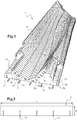
- the invention makes it possible to produce a mold or master model 1 having a complex shaped molding surface, in particular for molding hulls of boats or surface or deep-sea vessels, by implementing a set of couples.
- An example of such a mold or master model is given on the Figure 1 .
- the length of such a master model can be from a few meters to several tens of meters, with a width of several meters, and with pairs spaced 50 cm to a few meters between them.
- Each pair 2a, 2b, 2c ... is a flat panel, solid, extended and comprising at least a lower edge 9 and an upper edge 8.
- the upper edge 8 of the pair is intended to achieve the complex shape of the master model and it is thus cut according to a section of the useful surface of this model master.
- the pairs 2a, 2b, 2c ... vertically are placed on a support, by their lower edges 9, parallel to each other, and are held together by at least 3 notched spars 11.
- the elements surface 5 are finally installed between the upper edges 8 of the pairs 2a, 2b, 2c ... in order to form the complex surface of the mold or master model 1.
- the pairs are installed on a support which comprises means for positioning and maintaining the couples themselves.
- the means for positioning and holding the support are, for example, notches, either of the lower edge of the pairs, or of the support, or both, and in the latter case said notches are preferably complementary to fit into each other. others in pairs.
- the means for positioning and holding the support may also comprise jaw clamping means capable of engaging the couples, said clamping means being preferably adjustable in position.
- the supports are shown schematically by beams 4.
- the pairs 2a, 2b, 2c ... are arranged transversely with respect to the length of the master model 1.
- These pairs are preferably panels which have good rigidity and which are easily machinable. If the panels are preferably wood or wood-based, they may be partly or wholly metallic. It may be the same for the longitudinal members.
- the pairs 2a, 2b, 2c comprise elongated straight / linear slots of given length and width and which form alignments between the successive adjacent pairs along the length of the master pattern or a part of this length and in which alignments slits 10 is put on the longitudinal members 3, 3a, 3b ... shaped elongate plates.
- the slots of the couples 10 are in full and therefore do not open on an edge 8, 9 of torque 2a, 2b, 2c ...
- these slot alignments 10 are made on a subset of the slots and thus couples 2a, 2b, 2c ... successive successive corresponding.
- the longitudinal members may be of the length of the master model or may be shorter than the length of the model master and may then, if desired, designate them as "single spars".
- the stringers are arranged in series and so that there is overlap of neighboring / adjacent beams to the corresponding ends of the longitudinal members 3 on the minus two adjacent pairs.
- the length, height in this case, of the slots 10 is greater or nearly equal to the width or height I of the spar 3 and, preferably, the thickness of the spar is substantially equal to the width of the slot to allow both to pass the spar into the slots through the pairs and to obtain a minimum clearance between the pairs and the spar 3 at least at the slots 10.
- the width of the slots 10 is greater than the thickness of the spar to facilitate the action of threading the spar 3 through the pairs 2a, 2b, 2c ... If, preferably, the slots 10 are rectangular openings through the pairs 2a, 2b, 2c ..., in variants they may have truncated triangular shapes.
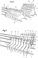
- the longitudinal spar 3 comprises, along one of its two edges of length L, notches 11 perpendicular to said edge. These notches are made so that, once the spar introduced and threaded along its length through the subset of adjacent pairs of slots, the spar 3 can slide / translate, transversely, according to its width / height along the slots in order to release a portion of said slots of the subassembly and thus to allow the maintenance of couples.
- the beam moves in a direction carried by planes parallel to the pairs and, therefore, perpendicular to the direction that the spar 3 had followed during its prior introduction by threading through the different slots 10 and which is shown schematically by the thickened arrow 6 on the Figure 4 .
- the width of the notch 11 is substantially equal to the thickness of the torque in its corresponding portion of sliding / translation so that once the spar on and then translated, the game is minimum between the pairs and the spar at least at the notches.
- each of the pairs of panels may comprise guides, on the one hand, along the two lengthwise edges of the slot considered, and / or, on the other hand, in continuity with the slot on the torque panel along the two axes of these two slot length edges.
- the guides are on the side of the end of the slot to which is made the transverse translation of the spar.
- These guides may be on one side / face of the couple or on both sides.
- These guides are for example made with an L-shaped angle, so two wings perpendicular to each other. On one of the two wings will support the surface of the spar and the other wing being fixed / secured to the surface of the panel of the couple.
- the guides are present only along the edges of the slot and result from a deformation of the metal by repoussage having succeeded in opening the slot.
- the notches 11 are formed along only one of the two lengthwise edges L of the spar 3.
- the spacings between the notches are different between the two length edges of the spar to be able to use the same noton spar for two different arrangements of the corresponding pairs by turning the spar.
- the notched spar 3 has a number of notches equal to the number of pairs that it maintains along its length
- the notched spar has a number of notches greater than the number of pairs that it keeps on its length L.
- a given pair comprises at least two slots 10, each of the slots of said pair belonging to a distinct subset of adjacent pairs of slots and for which subassembly, a spar is provided.
- each of the slots of the pair belongs to a distinct subset of adjacent pairs of slots receiving its own spar.
- the slots are distributed substantially regularly on the surface of the torque and on the width of the torque. For example, there may be a slot to each end of the width (laterally) of the pair and one or more other slots between the two end / side.
- the slots of a given pair are in planes of slots that are not parallel to each other and that the planes carried by the connected and connected side rails are not parallel to each other. and, preferably, these planes have the same direction which corresponds to the length of the master pattern and they are therefore perpendicular to the pairs.
- a model master structure has been considered in which the pairs are vertical and perpendicular to the length of the model master and longitudinal members parallel to this model master length and therefore perpendicular to the couples. It is understood that in the case where the master model is made with pairs parallel to each other but no longer vertical but inclined, the notches are then no longer perpendicular to the length edge of the spar but inclined as the pairs. Other arrangements of the pairs between them are possible and, for example non-parallel to each other, for example radial in the case where the master model must form a curved elongated element, and in such cases, the orientations of the notches and the spacings between notches will be adapted.
- Curved beams may even be provided in the case of a radial or star arrangement of the pairs.
- the plane of alignment of the slots of a subset of slots may be non-perpendicular to the pairs.
- the spar instead of being planar can be bypassed.
- each slot is made in pairs and the two slots of a pair are parallel to each other and adjacent to each other.
- This arrangement in pairs of slots 10 is better visible on the Figure 3 where the 2x foreground couple has been made transparent and we can see the background pair 2y (dashed underline to signify that it is seen in transparency).
- the two slots 10 of the background pair 2y (marked with dashed arrows to signify that they are viewed in transparency) are aligned with those of the foreground pair 2x.
- a 3x spar was threaded and translated into one of the two slots of each pair and through the two couples 2x, 2y, the two slots concerned being aligned so that the spar which is here a straight plate can pass.
- This embodiment of paired slots is particularly advantageous in the case where the stringers have a length less than the length of the master pattern and they must be put in series with overlapping of their corresponding ends through at least one, preferably two (or more) adjacent pairs. Indeed, this overlap requires a lateral shift of a first spar to the next along the serialization because a given slot can receive a spar.
- the first spar ends in the first slot of the pair of slots and the next spar begins, at the overlap between two close pairs, in the second slot of said pair of slots with a reduced lateral shift from one spar to the next and while remaining in parallel planes between them, the two slots of the pair being close and parallel.
- a locking blade which is introduced into the portion released from at least one of the slots having received a spar, the width of the locking blade being substantially equal to the length of the portion released from the slot following the translation of the spar to block in the slot the spar and slipped translated.
- This locking blade may be triangular in shape to form a wedge that will be easier to thread into the slot.
- the locking blade forms a keying.
- secondary beams with notches are also used, and these secondary beams are threaded along their lengths into the slots after the initial beams have been threaded and translated. It is understood that the width or height of the secondary spar must be less than or equal to the length of the portion released from the slot following the translation of the initial spar. Similarly, the notches of the secondary spar must be oriented opposite to that of the notches of the initial spar because said notches of the secondary spar are intended to come opposite corresponding pairs on the opposite side to the initial spar of the slot. The secondary spar is also translated along its width along the slot but in a direction opposite to the translation that had made the initial spar. To lock the assembly, a groove blade is then introduced into at least one of the slots between the initial spar and the secondary spar to block these two side members slid towards the two opposite sides of the slot.
- pairs 2a, 2b, 2c ..., apart from the specific shape of their upper edges 8, are relatively simple to manufacture with respect to the slots 10 because they are identical / stackable for a certain number of couples, or all couples especially when the slots are made in pairs.
- the present invention is not limited to the particular embodiments which have just been described, but extends to all variants and equivalents in accordance with its spirit.
- the invention can be declined according to many other possibilities without departing from the scope defined by the description and the claims.
- the beams may be T-shaped or L-shaped and in this case the width and / or shape of the slot will be adapted accordingly.
- the master model can be dismantled and reassembled, it is possible, in a variant, to use definitive fastening means between the torques and the longitudinal members, the said definitive fastening means typically being collages, welds or solders.
- the master torque 1 which makes it possible to make moldings of large parts, is not limited to maritime applications but can be applied to other fields such as, for example, the molding of an aircraft wing in aeronautics.
Landscapes
- Engineering & Computer Science (AREA)
- Mechanical Engineering (AREA)
- Toys (AREA)
- Connection Of Plates (AREA)
- Moulds For Moulding Plastics Or The Like (AREA)
Claims (11)
- Mastermodell (1) mit einer Nutzfläche komplexer Form, insbesondere zum Formen von Boots- oder Schiffskörpern, das eine Gesamtheit von nebeneinander angeordneten Paaren (2a, 2b, 2c ...) aufweist, wobei jedes Paar (2a, 2b, 2c ...) eine Platte mit wenigstens einem Nutzrand (8) aufweist, um einen entsprechenden Querschnitt der Nutzfläche zu bilden, wobei die Paare (2a, 2b, 2c ...) zueinander parallel angeordnet und mit vorbestimmten Zwischenräumen so zusammengehalten werden, daß deren Nutzränder (8) die gewünschte Nutzfläche bilden,
dadurch gekennzeichnet, daß die Platte jedes Paars (2a, 2b, 2c ...) wenigstens einen Schlitz (10) aufweist, der eine in der Dicke durchgehende und nicht mündende Öffnung bildet, und
daß die Paare (2a, 2b, 2c ...) durch wenigstens einen Längsträger (3, 3a, 3b ...) zusammengehalten werden, der dazu ausgelegt ist, der Länge (L) nach durch die Schlitze (10) der Paare hindurch eingezogen (6) zu werden, und der quer verlaufende Aussparungen (11) zum Aufnehmen und Festhalten der Paare (2a, 2b, 2c ...) aufweist, wobei jede Aussparung (11) dazu ausgelegt ist, nachdem der Längsträger eingezogen worden ist und aufgrund der relativen Querverlagerung (7) des Längsträgers gegenüber den Paaren, den entsprechenden Teil der Platte jedes Paars (2a, 2b, 2c ...) aufzunehmen. - Mastermodell gemäß Anspruch 1, dadurch gekennzeichnet, daß die Breite jeder Aussparung wenigstens im betreffenden Bereich des Paars im Wesentlichen gleich der Dicke des entsprechenden Paars (2a, 2b, 2c ...) ist, damit das Spiel zwischen dem betreffenden Paar und dem Längsträger minimal ist.
- Mastermodell gemäß Anspruch 2, dadurch gekennzeichnet, daß die Form und die Dicke des Längsträgers (3, 3a, 3b ...) praktisch gleich jener der Schlitze (10) ist, in die dieser eingezogen wird, damit dann, wenn der Längsträger eingezogen und dann quer verlagert worden ist, um die Paare (2a, 2b, 2c ...) in die Aussparungen (11) einzufügen, das Spiel zwischen dem betreffenden Paar und dem Längsträger minimal ist.
- Mastermodell gemäß einem der vorangehenden Ansprüche, dadurch gekennzeichnet, daß der Längsträger (3, 3a, 3b ...) zwei voneinander abgewandte Längsränder (L) hat und entlang dieser beiden Längsränder quer verlaufende Aussparungen (11) aufweist.
- Mastermodell gemäß einem der vorangehenden Ansprüche, dadurch gekennzeichnet, daß jedes Paar (2a, 2b, 2c ...) wenigstens zwei Schlitze aufweist und daß die Paare (2a, 2b, 2c ...) mittels wenigstens zweier Längsträger (3, 3a, 3b ...), die eine flache Form haben und von denen jeder in einen zugehörigen Schlitz jedes Paars (2a, 2b, 2c ...) eingezogen ist, derart zusammengefügt sind, daß sich die größte Abmessung des Querschnitts eines Längsträgers in einer zu der eines anderen Längsträgers im Wesentlichen nicht parallelen Richtung erstreckt.
- Mastermodell gemäß einem der vorangehenden Ansprüche, dadurch gekennzeichnet, daß in den Paaren (2a, 2b, 2c ...) wenigstens einige der Schlitze (10) paarweise ausgeführt sind, wobei die Schlitze eines Paars zueinander parallel und benachbart sind.
- Mastermodell gemäß einem der vorangehenden Ansprüche, dadurch gekennzeichnet, daß die Paare (2a, 2b, 2c ...) auf einer Unterlage (4) angeordnet sind, wobei die Unterlage Mittel zum Positionieren und Festhalten der Paare vor dem Einsetzen des Längsträgers (3, 3a, 3b ...) aufweist.
- Mastermodell gemäß einem der vorangehenden Ansprüche, dadurch gekennzeichnet, daß der wenigstens eine Längsträger aus einer Reihe von einzelnen Längsträgern (3, 3a, 3b ...) gebildet ist, von denen jeder eine Einzellänge aufweist, die kleiner als die Länge des Mastermodells ist, und die in quer zueinander versetzten Reihen über die Länge des Mastermodells (1) und mit Überlappungen der aneinander liegenden Enden durch wenigstens zwei aneinander liegende Paare (2a, 2b, 2c ...) hindurch angeordnet sind.
- Mastermodell gemäß einem der vorangehenden Ansprüche, dadurch gekennzeichnet, daß eine Arretierplatte in einen freigelegten Teil wenigstens eines der Schlitze (10) eingeführt ist, um eine Keilverbindung zu bilden, wobei die Breite der Arretierplatte im Wesentlichen gleich der Länge des freigelegten Teils des Schlitzes ist, wenn der Längsträger (3, 3a, 3b ...) quer verlagert ist, um den verlagerten Längsträger im Schlitz (10) zu blockieren.
- Mastermodell gemäß Anspruch 9, dadurch gekennzeichnet, daß die Arretierplatte im Wesentlichen die gleiche Länge wie jene des entsprechenden Längsträgers aufweist.
- Kit zur Herstellung eines Mastermodells, das wenigstens Paare (2a, 2b, 2c ...) mit Schlitzen (10) und Längsträger (3, 3a, 3b ...) mit Aussparungen (11) aufweist, die die Herstellung eines Mastermodells gemäß einem der vorangehenden Ansprüche durch Einziehen (6) der Längsträger in die Schlitze und Verlagerung (7) der Aussparungen der Längsträger auf den Paaren ermöglicht.
Applications Claiming Priority (2)
| Application Number | Priority Date | Filing Date | Title |
|---|---|---|---|
| FR1457918A FR3024957B1 (fr) | 2014-08-21 | 2014-08-21 | Maitre modele de forme complexe, kit de realisation |
| PCT/FR2015/052228 WO2016027035A1 (fr) | 2014-08-21 | 2015-08-19 | Maître modèle de forme complexe, kit de réalisation |
Publications (2)
| Publication Number | Publication Date |
|---|---|
| EP3183103A1 EP3183103A1 (de) | 2017-06-28 |
| EP3183103B1 true EP3183103B1 (de) | 2018-09-12 |
Family
ID=51688317
Family Applications (1)
| Application Number | Title | Priority Date | Filing Date |
|---|---|---|---|
| EP15759910.1A Active EP3183103B1 (de) | 2014-08-21 | 2015-08-19 | Mastermodell mit komplexer form und kit zur herstellung davon |
Country Status (4)
| Country | Link |
|---|---|
| US (1) | US10513055B2 (de) |
| EP (1) | EP3183103B1 (de) |
| FR (1) | FR3024957B1 (de) |
| WO (1) | WO2016027035A1 (de) |
Families Citing this family (3)
| Publication number | Priority date | Publication date | Assignee | Title |
|---|---|---|---|---|
| EP3743268B1 (de) * | 2018-01-24 | 2023-05-24 | LM Wind Power A/S | Verfahren und form zur herstellung von vorformlingen für ein windturbinenrotorblatt |
| US11801619B2 (en) * | 2021-10-05 | 2023-10-31 | The Boeing Company | Rapid tooling layup mandrel |
| DE102023128415A1 (de) * | 2023-10-17 | 2025-04-17 | Deutsches Zentrum für Luft- und Raumfahrt e.V. | Formwerkzeug und Verfahren zur Herstellung von Faserverbundwerkstoffkomponenten |
Family Cites Families (6)
| Publication number | Priority date | Publication date | Assignee | Title |
|---|---|---|---|---|
| US1837078A (en) * | 1929-04-23 | 1931-12-15 | Raymond D Sullivan | Ship hull construction |
| FR2598648A1 (fr) * | 1986-05-16 | 1987-11-20 | Perriere Bernard | Moule pour la fabrication de pieces composites, et procede en vue de son obtention |
| EP0981411A4 (de) * | 1997-05-06 | 2003-06-25 | Boeing Co | Hybrides auflegewerkzeug |
| US7112299B2 (en) * | 2003-07-09 | 2006-09-26 | Michael Merrick | Systems and methods for fabricating composite fiberglass laminate articles |
| EP2800657B1 (de) * | 2012-01-04 | 2016-03-16 | Dencam Composite A/S | Mastermodellstruktur |
| DE102012202376B4 (de) * | 2012-02-16 | 2014-09-11 | Senvion Se | Direktform für Rotorblätter für Windenergieanlagen |
-
2014
- 2014-08-21 FR FR1457918A patent/FR3024957B1/fr active Active
-
2015
- 2015-08-19 EP EP15759910.1A patent/EP3183103B1/de active Active
- 2015-08-19 WO PCT/FR2015/052228 patent/WO2016027035A1/fr not_active Ceased
- 2015-08-19 US US15/504,420 patent/US10513055B2/en active Active
Non-Patent Citations (1)
| Title |
|---|
| None * |
Also Published As
| Publication number | Publication date |
|---|---|
| US20170239849A1 (en) | 2017-08-24 |
| WO2016027035A1 (fr) | 2016-02-25 |
| FR3024957B1 (fr) | 2016-08-19 |
| FR3024957A1 (fr) | 2016-02-26 |
| US10513055B2 (en) | 2019-12-24 |
| EP3183103A1 (de) | 2017-06-28 |
Similar Documents
| Publication | Publication Date | Title |
|---|---|---|
| CA2868850C (fr) | Dispositif de fixation d'un equipement sur un panneau | |
| EP3131746B1 (de) | Polygonales teil mit hohlräumen für einen paneelkern, insbesondere eines satellitenantennenreflektors | |
| EP3183103B1 (de) | Mastermodell mit komplexer form und kit zur herstellung davon | |
| FR2881205A1 (fr) | Ensemble d'elements pour l'obtention d'un panneau | |
| FR2988275A1 (fr) | Caisson de meuble | |
| EP2492435B1 (de) | Skelett in einem Bausatz für feststehende, schwenkbare oder schiebbare Tür- oder Fensterflügel oder Ähnliches | |
| FR2718473A1 (fr) | Glissière de sécurité pour bordures de voies de circulation. | |
| WO2013021142A1 (fr) | Dispositif pour la mise en forme d'une tole par matriçage | |
| EP0329753B1 (de) | Wandschalung und verfahren zu ihrer herstellung | |
| EP2765259A1 (de) | Vertikales Abschirmungssystem | |
| EP1237780A1 (de) | Klarsichtfenster und sein herstellungsverfahren | |
| FR3004067A1 (fr) | Profile, notamment metallique, destine a permettre une fixation d'un film sur une structure de serre et systeme de fixation d'un film sur une structure de serre comprenant un tel profile | |
| WO2008145856A2 (fr) | Element d'assemblage d'angle pour coffrage et coffrage ainsi obtenu | |
| EP3443864A1 (de) | Scharnier, mit gelenken ausgestattete vorrichtung, die ein solches scharnier umfasst oder aus einem solchen scharnier besteht, und herstellungsverfahren eines solchen scharniers | |
| EP2290174A1 (de) | Zaunpfosten | |
| FR3044723A1 (fr) | Ensemble de montage a rainures inclinees | |
| EP3221207B1 (de) | Anordnung zur verstärkung von einsätzen aus einem polymermaterial mit trennbaren verstärkungseinsätzen | |
| CA3181671A1 (fr) | Procede de fabrication d'une poutre a section fermee | |
| FR2979367A1 (fr) | Mannequin pour la fabrication d'ouverture dans du beton coule | |
| FR2938412A1 (fr) | Chassis entoile demontable et son dispositif de liaison et d'ecartement de ses montants creux ou evides | |
| CH347967A (fr) | Coffrage pour le moulage d'un matériau tel que du béton | |
| FR2668524A1 (fr) | Procede de fabrication de coffrages et coffrages pour l'execution de parois a profil curviligne ou angulaire. | |
| FR3083557A1 (fr) | Dispositif de fixation de cloture a embase invisible | |
| FR2997116A1 (fr) | Mannequin pour la fabrication d'ouverture dans du beton coule | |
| EP0701032A1 (de) | Modularer Umfassungs-Satz zum Abgrenzen eines erweiterbaren, umschlossenen Rauminhaltes |
Legal Events
| Date | Code | Title | Description |
|---|---|---|---|
| STAA | Information on the status of an ep patent application or granted ep patent |
Free format text: STATUS: THE INTERNATIONAL PUBLICATION HAS BEEN MADE |
|
| PUAI | Public reference made under article 153(3) epc to a published international application that has entered the european phase |
Free format text: ORIGINAL CODE: 0009012 |
|
| STAA | Information on the status of an ep patent application or granted ep patent |
Free format text: STATUS: REQUEST FOR EXAMINATION WAS MADE |
|
| 17P | Request for examination filed |
Effective date: 20170213 |
|
| AK | Designated contracting states |
Kind code of ref document: A1 Designated state(s): AL AT BE BG CH CY CZ DE DK EE ES FI FR GB GR HR HU IE IS IT LI LT LU LV MC MK MT NL NO PL PT RO RS SE SI SK SM TR |
|
| AX | Request for extension of the european patent |
Extension state: BA ME |
|
| DAV | Request for validation of the european patent (deleted) | ||
| DAX | Request for extension of the european patent (deleted) | ||
| GRAP | Despatch of communication of intention to grant a patent |
Free format text: ORIGINAL CODE: EPIDOSNIGR1 |
|
| STAA | Information on the status of an ep patent application or granted ep patent |
Free format text: STATUS: GRANT OF PATENT IS INTENDED |
|
| INTG | Intention to grant announced |
Effective date: 20180412 |
|
| GRAS | Grant fee paid |
Free format text: ORIGINAL CODE: EPIDOSNIGR3 |
|
| GRAA | (expected) grant |
Free format text: ORIGINAL CODE: 0009210 |
|
| STAA | Information on the status of an ep patent application or granted ep patent |
Free format text: STATUS: THE PATENT HAS BEEN GRANTED |
|
| AK | Designated contracting states |
Kind code of ref document: B1 Designated state(s): AL AT BE BG CH CY CZ DE DK EE ES FI FR GB GR HR HU IE IS IT LI LT LU LV MC MK MT NL NO PL PT RO RS SE SI SK SM TR |
|
| REG | Reference to a national code |
Ref country code: GB Ref legal event code: FG4D Free format text: NOT ENGLISH |
|
| REG | Reference to a national code |
Ref country code: CH Ref legal event code: EP |
|
| REG | Reference to a national code |
Ref country code: IE Ref legal event code: FG4D Free format text: LANGUAGE OF EP DOCUMENT: FRENCH |
|
| REG | Reference to a national code |
Ref country code: DE Ref legal event code: R096 Ref document number: 602015016235 Country of ref document: DE |
|
| REG | Reference to a national code |
Ref country code: AT Ref legal event code: REF Ref document number: 1040020 Country of ref document: AT Kind code of ref document: T Effective date: 20181015 |
|
| REG | Reference to a national code |
Ref country code: NL Ref legal event code: FP |
|
| REG | Reference to a national code |
Ref country code: LT Ref legal event code: MG4D |
|
| PG25 | Lapsed in a contracting state [announced via postgrant information from national office to epo] |
Ref country code: GR Free format text: LAPSE BECAUSE OF FAILURE TO SUBMIT A TRANSLATION OF THE DESCRIPTION OR TO PAY THE FEE WITHIN THE PRESCRIBED TIME-LIMIT Effective date: 20181213 Ref country code: NO Free format text: LAPSE BECAUSE OF FAILURE TO SUBMIT A TRANSLATION OF THE DESCRIPTION OR TO PAY THE FEE WITHIN THE PRESCRIBED TIME-LIMIT Effective date: 20181212 Ref country code: RS Free format text: LAPSE BECAUSE OF FAILURE TO SUBMIT A TRANSLATION OF THE DESCRIPTION OR TO PAY THE FEE WITHIN THE PRESCRIBED TIME-LIMIT Effective date: 20180912 Ref country code: FI Free format text: LAPSE BECAUSE OF FAILURE TO SUBMIT A TRANSLATION OF THE DESCRIPTION OR TO PAY THE FEE WITHIN THE PRESCRIBED TIME-LIMIT Effective date: 20180912 Ref country code: LT Free format text: LAPSE BECAUSE OF FAILURE TO SUBMIT A TRANSLATION OF THE DESCRIPTION OR TO PAY THE FEE WITHIN THE PRESCRIBED TIME-LIMIT Effective date: 20180912 Ref country code: SE Free format text: LAPSE BECAUSE OF FAILURE TO SUBMIT A TRANSLATION OF THE DESCRIPTION OR TO PAY THE FEE WITHIN THE PRESCRIBED TIME-LIMIT Effective date: 20180912 Ref country code: BG Free format text: LAPSE BECAUSE OF FAILURE TO SUBMIT A TRANSLATION OF THE DESCRIPTION OR TO PAY THE FEE WITHIN THE PRESCRIBED TIME-LIMIT Effective date: 20181212 |
|
| PG25 | Lapsed in a contracting state [announced via postgrant information from national office to epo] |
Ref country code: LV Free format text: LAPSE BECAUSE OF FAILURE TO SUBMIT A TRANSLATION OF THE DESCRIPTION OR TO PAY THE FEE WITHIN THE PRESCRIBED TIME-LIMIT Effective date: 20180912 Ref country code: HR Free format text: LAPSE BECAUSE OF FAILURE TO SUBMIT A TRANSLATION OF THE DESCRIPTION OR TO PAY THE FEE WITHIN THE PRESCRIBED TIME-LIMIT Effective date: 20180912 Ref country code: AL Free format text: LAPSE BECAUSE OF FAILURE TO SUBMIT A TRANSLATION OF THE DESCRIPTION OR TO PAY THE FEE WITHIN THE PRESCRIBED TIME-LIMIT Effective date: 20180912 |
|
| REG | Reference to a national code |
Ref country code: AT Ref legal event code: MK05 Ref document number: 1040020 Country of ref document: AT Kind code of ref document: T Effective date: 20180912 |
|
| PG25 | Lapsed in a contracting state [announced via postgrant information from national office to epo] |
Ref country code: PL Free format text: LAPSE BECAUSE OF FAILURE TO SUBMIT A TRANSLATION OF THE DESCRIPTION OR TO PAY THE FEE WITHIN THE PRESCRIBED TIME-LIMIT Effective date: 20180912 Ref country code: IS Free format text: LAPSE BECAUSE OF FAILURE TO SUBMIT A TRANSLATION OF THE DESCRIPTION OR TO PAY THE FEE WITHIN THE PRESCRIBED TIME-LIMIT Effective date: 20190112 Ref country code: ES Free format text: LAPSE BECAUSE OF FAILURE TO SUBMIT A TRANSLATION OF THE DESCRIPTION OR TO PAY THE FEE WITHIN THE PRESCRIBED TIME-LIMIT Effective date: 20180912 Ref country code: CZ Free format text: LAPSE BECAUSE OF FAILURE TO SUBMIT A TRANSLATION OF THE DESCRIPTION OR TO PAY THE FEE WITHIN THE PRESCRIBED TIME-LIMIT Effective date: 20180912 Ref country code: AT Free format text: LAPSE BECAUSE OF FAILURE TO SUBMIT A TRANSLATION OF THE DESCRIPTION OR TO PAY THE FEE WITHIN THE PRESCRIBED TIME-LIMIT Effective date: 20180912 Ref country code: RO Free format text: LAPSE BECAUSE OF FAILURE TO SUBMIT A TRANSLATION OF THE DESCRIPTION OR TO PAY THE FEE WITHIN THE PRESCRIBED TIME-LIMIT Effective date: 20180912 Ref country code: EE Free format text: LAPSE BECAUSE OF FAILURE TO SUBMIT A TRANSLATION OF THE DESCRIPTION OR TO PAY THE FEE WITHIN THE PRESCRIBED TIME-LIMIT Effective date: 20180912 |
|
| PG25 | Lapsed in a contracting state [announced via postgrant information from national office to epo] |
Ref country code: SM Free format text: LAPSE BECAUSE OF FAILURE TO SUBMIT A TRANSLATION OF THE DESCRIPTION OR TO PAY THE FEE WITHIN THE PRESCRIBED TIME-LIMIT Effective date: 20180912 Ref country code: PT Free format text: LAPSE BECAUSE OF FAILURE TO SUBMIT A TRANSLATION OF THE DESCRIPTION OR TO PAY THE FEE WITHIN THE PRESCRIBED TIME-LIMIT Effective date: 20190112 Ref country code: SK Free format text: LAPSE BECAUSE OF FAILURE TO SUBMIT A TRANSLATION OF THE DESCRIPTION OR TO PAY THE FEE WITHIN THE PRESCRIBED TIME-LIMIT Effective date: 20180912 |
|
| REG | Reference to a national code |
Ref country code: DE Ref legal event code: R097 Ref document number: 602015016235 Country of ref document: DE |
|
| PLBE | No opposition filed within time limit |
Free format text: ORIGINAL CODE: 0009261 |
|
| STAA | Information on the status of an ep patent application or granted ep patent |
Free format text: STATUS: NO OPPOSITION FILED WITHIN TIME LIMIT |
|
| PG25 | Lapsed in a contracting state [announced via postgrant information from national office to epo] |
Ref country code: DK Free format text: LAPSE BECAUSE OF FAILURE TO SUBMIT A TRANSLATION OF THE DESCRIPTION OR TO PAY THE FEE WITHIN THE PRESCRIBED TIME-LIMIT Effective date: 20180912 |
|
| 26N | No opposition filed |
Effective date: 20190613 |
|
| PG25 | Lapsed in a contracting state [announced via postgrant information from national office to epo] |
Ref country code: SI Free format text: LAPSE BECAUSE OF FAILURE TO SUBMIT A TRANSLATION OF THE DESCRIPTION OR TO PAY THE FEE WITHIN THE PRESCRIBED TIME-LIMIT Effective date: 20180912 |
|
| PG25 | Lapsed in a contracting state [announced via postgrant information from national office to epo] |
Ref country code: TR Free format text: LAPSE BECAUSE OF FAILURE TO SUBMIT A TRANSLATION OF THE DESCRIPTION OR TO PAY THE FEE WITHIN THE PRESCRIBED TIME-LIMIT Effective date: 20180912 |
|
| PG25 | Lapsed in a contracting state [announced via postgrant information from national office to epo] |
Ref country code: LI Free format text: LAPSE BECAUSE OF NON-PAYMENT OF DUE FEES Effective date: 20190831 Ref country code: MC Free format text: LAPSE BECAUSE OF FAILURE TO SUBMIT A TRANSLATION OF THE DESCRIPTION OR TO PAY THE FEE WITHIN THE PRESCRIBED TIME-LIMIT Effective date: 20180912 Ref country code: LU Free format text: LAPSE BECAUSE OF NON-PAYMENT OF DUE FEES Effective date: 20190819 Ref country code: CH Free format text: LAPSE BECAUSE OF NON-PAYMENT OF DUE FEES Effective date: 20190831 |
|
| REG | Reference to a national code |
Ref country code: BE Ref legal event code: MM Effective date: 20190831 |
|
| PG25 | Lapsed in a contracting state [announced via postgrant information from national office to epo] |
Ref country code: IE Free format text: LAPSE BECAUSE OF NON-PAYMENT OF DUE FEES Effective date: 20190819 |
|
| PG25 | Lapsed in a contracting state [announced via postgrant information from national office to epo] |
Ref country code: BE Free format text: LAPSE BECAUSE OF NON-PAYMENT OF DUE FEES Effective date: 20190831 |
|
| PG25 | Lapsed in a contracting state [announced via postgrant information from national office to epo] |
Ref country code: CY Free format text: LAPSE BECAUSE OF FAILURE TO SUBMIT A TRANSLATION OF THE DESCRIPTION OR TO PAY THE FEE WITHIN THE PRESCRIBED TIME-LIMIT Effective date: 20180912 |
|
| PG25 | Lapsed in a contracting state [announced via postgrant information from national office to epo] |
Ref country code: HU Free format text: LAPSE BECAUSE OF FAILURE TO SUBMIT A TRANSLATION OF THE DESCRIPTION OR TO PAY THE FEE WITHIN THE PRESCRIBED TIME-LIMIT; INVALID AB INITIO Effective date: 20150819 Ref country code: MT Free format text: LAPSE BECAUSE OF FAILURE TO SUBMIT A TRANSLATION OF THE DESCRIPTION OR TO PAY THE FEE WITHIN THE PRESCRIBED TIME-LIMIT Effective date: 20180912 |
|
| REG | Reference to a national code |
Ref country code: FR Ref legal event code: PLFP Year of fee payment: 8 |
|
| PG25 | Lapsed in a contracting state [announced via postgrant information from national office to epo] |
Ref country code: MK Free format text: LAPSE BECAUSE OF FAILURE TO SUBMIT A TRANSLATION OF THE DESCRIPTION OR TO PAY THE FEE WITHIN THE PRESCRIBED TIME-LIMIT Effective date: 20180912 |
|
| REG | Reference to a national code |
Ref country code: NL Ref legal event code: HC Owner name: EXAIL; FR Free format text: DETAILS ASSIGNMENT: CHANGE OF OWNER(S), CHANGE OF OWNER(S) NAME; FORMER OWNER NAME: IXBLUE Effective date: 20230404 |
|
| P01 | Opt-out of the competence of the unified patent court (upc) registered |
Effective date: 20230524 |
|
| REG | Reference to a national code |
Ref country code: DE Ref legal event code: R081 Ref document number: 602015016235 Country of ref document: DE Owner name: EXAIL SAS, FR Free format text: FORMER OWNER: IXBLUE, SAINT-GERMAIN-EN-LAYE, FR |
|
| PGFP | Annual fee paid to national office [announced via postgrant information from national office to epo] |
Ref country code: NL Payment date: 20250821 Year of fee payment: 11 |
|
| PGFP | Annual fee paid to national office [announced via postgrant information from national office to epo] |
Ref country code: DE Payment date: 20250718 Year of fee payment: 11 |
|
| PGFP | Annual fee paid to national office [announced via postgrant information from national office to epo] |
Ref country code: IT Payment date: 20250725 Year of fee payment: 11 |
|
| PGFP | Annual fee paid to national office [announced via postgrant information from national office to epo] |
Ref country code: GB Payment date: 20250717 Year of fee payment: 11 |
|
| PGFP | Annual fee paid to national office [announced via postgrant information from national office to epo] |
Ref country code: FR Payment date: 20250717 Year of fee payment: 11 |