EP3183175B1 - Machine permettant d'appliquer des étiquettes-manchons rétractables et procédé d'application desdites étiquettes - Google Patents
Machine permettant d'appliquer des étiquettes-manchons rétractables et procédé d'application desdites étiquettes Download PDFInfo
- Publication number
- EP3183175B1 EP3183175B1 EP14799024.6A EP14799024A EP3183175B1 EP 3183175 B1 EP3183175 B1 EP 3183175B1 EP 14799024 A EP14799024 A EP 14799024A EP 3183175 B1 EP3183175 B1 EP 3183175B1
- Authority
- EP
- European Patent Office
- Prior art keywords
- containers
- labels
- machine
- label
- container
- Prior art date
- Legal status (The legal status is an assumption and is not a legal conclusion. Google has not performed a legal analysis and makes no representation as to the accuracy of the status listed.)
- Not-in-force
Links
Images



Classifications
-
- B—PERFORMING OPERATIONS; TRANSPORTING
- B65—CONVEYING; PACKING; STORING; HANDLING THIN OR FILAMENTARY MATERIAL
- B65C—LABELLING OR TAGGING MACHINES, APPARATUS, OR PROCESSES
- B65C3/00—Labelling other than flat surfaces
- B65C3/06—Affixing labels to short rigid containers
- B65C3/065—Affixing labels to short rigid containers by placing tubular labels around the container
Definitions
- the present invention relates to a machine for applying shrink sleeve labels and to a process for applying said shrink sleeve labels.
- the invention refers to the field of labelling different containers (e.g. bottles, cups or bottles, either made up of glass or of plastics).
- containers e.g. bottles, cups or bottles, either made up of glass or of plastics.
- labelling of containers for food products or for other products can be made by using labels comprised of a plastic film, mainly a printed film, having the property of shrinking when subjected to the heat action, and usually known as heat shrinking film.
- Heat shrinking film has a thin thickness, approximately ranging between 30 and 75 microns, and can be realised by different polymers.
- said film is comprised of PVC, PET or OPS.
- Said labels are usually realised by folding and welding (or gluing) a film band so as to obtain a tubular element, thus joining the two ends of the film band along a line that can be assimilated to a generatrix of the cylinder so obtained.
- Tubular element is flattened and wound as a bobbin, said bobbin supplying machines applying labels obtained from said material by a transverse cut of portions having a set length.
- Said labels are known as "shrink sleeves", the shrinking properties of which are activated by exposure to the heat. They are applied with, or without the use of glue.
- Labelling machines exist, usually and advantageously associated to and provided downward to, machines of the FFS (Form, Fill and Seal) type, i.e. machines that can realise by thermoforming, a continuous band of container, provided one after the other, said containers being coupled each other by the upper part of the same thermoformed band.
- FFS Form, Fill and Seal
- containers are filled with the product (e.g. water or yoghurt), and then the upper opening is sealed, while in the final step a cut is carried out on the upper part of the thermoformed container, said cut being made along the perimeter of the opening of the container, thus permitting separation of single containers.
- HFFS horizontal FFS machines
- horizontal linear advancement direction wherein by "horizontal” it is meant a direction substantially parallel with respect to the floor or to the resting plane of the machine) along which different container thermoforming process steps are carried out, i.e. filling, closure and cutting in the relevant stations.
- FS Food and Seal machines
- said machine starting with already formed cups, stacked each other, that are inserted within the machine, which is similar to the FFS machine, without the provision of the thermoforming step and of the final cut.
- each step of the cycle is carried out blocking advancement of continuous band (for FFS machine) on which containers are obtained in correspondence of the relevant working station, and when the step is terminated, they are moved again until blocking the same in correspondence of the following working station.
- continuous band for FFS machine
- machines for applying shrink sleeve labels that must operate along with FFS or FS machines are so realized to provide separate steps and actuated according to a batch mode, said steps being distinct and successive each other, namely:
- Labelling steps of the container are thus carried out along said linear advancement direction, downward the FFS process, or integrated with the same.
- said time is not sufficient to conveniently carry out some operations, so that a solution permitting prolonging the same, even of few tenths of a second, would cause a reduction of efficiency and productivity of the FFS machine.
- said support and movement system for said containers can comprise a plurality of support elements comprising a plurality of cavities that can support at least a column of containers in an upright position and provided as a grid, i.e. spaced each other, and placed along parallel lines and columns.
- said support elements can be plates, preferably comprised of rigid material, and so shaped to have a plurality of holes for housing, from above, each container.
- said support elements can be transverse elements, parallel each other and provided transversely with respect to the linear advancement direction of the machine, said transverse elements being spaced each other so as to create a cavity to house a line of containers.
- said support elements can be comprised of mats made up of flexible material shaped to have a plurality of holes for housing, from above, each one of said containers.
- profile surface of said plurality of cavities can have the lower portion blunt, preferably with a 45° angle.
- said means for applying said labels comprises a column of shuttles for each column of containers, configured in such a way to be wound by the relevant label when said supply means have supplied a label on the same, support and pushing means for said label, and motion means for moving said pushing means with respect to said shuttle to apply said label on said container, said motion means being so configured to bring said application means from a rest position, wherein said label winds said shuttle and is supported by said support and pushing means, to an application position, wherein said label winds said container and is supported by said support and pushing means.
- said application means can comprise two support transverse elements, transversely provided with respect to the linear advancement direction, one above the other, each shuttle being integral with said upper support transverse element, said pushing means being integrally coupled with the lower support transverse element, said movement system being able to cause the displacement of the lower support transverse element with respect to the upper support transverse element to cause the displacement upward of said label with respect to the container to apply the label from the bottom on the same moving container.
- said application means can further comprise connection means between said transverse support elements.
- said application means can further comprise return means between said support transverse means in said rest position.
- said motion means of said application means comprises a cam ⁇ roll assembly, wherein said cam is fixed with respect to the resting plane of the machine and said roll is integral with said pushing means.
- said roll can be integral with said lower support transverse element.
- said heating means can comprise pre-heating means for partial shrinking of said labels on said containers, and heating means, downward said pre-heating means, for full shrinking said labels on said containers.
- said pre-heating means can comprise a pair of lateral hollow diffusers, placed according to a longitudinal direction with respect to the linear advancement direction, laterally with respect to each one at least one column of containers, so as to be aside said containers when the same are transported through said pre-heating means, said lateral hollow diffusers being provided with a longitudinal slot, said slot being placed so as to be in correspondence of a portion of said containers and being connected with a conduct for passage of a fluid through said slots to activate partial heat-shrinking of said labels on said portion of said containers.
- said pre-heating means can comprise a pair of lateral diffusers for each column of containers, each pair of lateral diffusers being offset, so that partial heat-shrinking of a column of containers occurs before heat-shrinking of the adjacent column.
- said heating means can comprise full heating means, including a channel longitudinal with respect to the linear advancement direction, for each column of containers, said longitudinal channel being connected to a fluid conduct and comprising a chamber with two outlet openings for fluid suitable to direct said fluid according to the direction of the walls of said channel for a uniform distribution of said fluid within said channel and to activate full heat-shrinking of said label on said container.
- said walls of said at least one channel can comprise a portion so shaped to deviate flow of the fluid toward a portion of said container and of said label.
- said heating means can comprise a suction hood.
- said means for supplying said labels can be provided along the linear advancement direction of said containers.
- said label supply means can be provided laterally with respect to the linear advancement direction of said containers and said application means can make a diagonal translational motion in order to be supplied with said labels in correspondence of said supply means and in order to be in correspondence of said containers to permit application from the bottom of said labels on said containers.
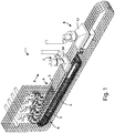
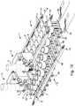
- figure 1 it is shown a preferred embodiment of the labelling machine according to the invention, indicated by reference number 1.
- Said machine 1 is realized to apply one or more shrink sleeve labels 2 to one or more containers 3 along a linear advancement direction A.
- said linear advancement direction A is horizontal, i.e. parallel with respect to the machine 1 resting plane.
- containers 3 have a frustum-conical shape, with the lower base 13, having the lower surface faced downward and the larger base 14 faced upward and having a perimeter edge 15 projecting with respect to the body of the same container 3.
- said containers 3 must be conveniently kept in an upright position, to prevent that its contents move and displace within the same.
- some food products are of the stratified type, e.g. a yoghourt with a layer of jam, and to fulfil with the needing of displaying it to the final consumer, said stratification must be maintained intact.
- shape of the container can be different, without departing from the scope of the present invention.
- sleeve labels 2 obtained from a heat-shrinkable material, preferably a plastic material, closed to realize a hollow cylinder having such dimensions to wind, even only partially, with respect to its height, the outer surface of the container 3 to be labelled.
- a machine 1 suitable for transporting and labelling at the same time four containers 3 placed along four columns of containers 3.
- the machine 1 according to the invention can be conveniently employed also to label a plurality of containers, according to the manufacturing needing and to the width of the manufacturing line.
- Machine 1 comprises a system 4 for supporting and moving one or more container 3 columns along the linear advancement direction A.
- Said support and motion system 4 is configured so as to make an endless continuous movement, for continuously transporting said one or more container 3 column, when they are supported by said support and motion system 4.
- support and motion system 4 comprises a plurality of support elements 9, able to support said containers 3 in an upright position and placed according to a grid pattern, i.e. spaced each other and along parallel lines and columns.
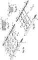
- support and motion system 4 comprises motion means 16 for said support elements 9, in this specific case two transmission chains 16 (e.g. partially shown in figures 2a, 2b and 5a - 5c ), connected on lateral edges of support elements 9and able displacing said support elements 9 with an endless continuous movement, thus creating a single chain element (as shown in figure 1 ).
- said support elements 9 are shaped so as to have a plurality of holes 10 for housing, from the above, each one of said containers 3, with their lower base 13 faced downward, so that upper edge 15 of the container can rest on the contour surface 17 of each hole 10 of the support element 9.
- said support elements 9 have a central line with four shaped holes 10 and two lines of hemi-holes 11 lateral with respect to said central line of holes 10, so that when a support element 9 is provided aside a further support element 9, hemi-holes 11 of support elements 9 placed side by side can support a further line of containers 3.
- Said support elements 9 are thus segments of a single chain, placed side by side so as to house a plurality of containers 3 and able to lie along a common plane during transportation of containers 3 and at the same time to rotate to adapt to the run of the transmission chain 16.
- Said support element 9 can be comprised of rigid material, e.g. aluminium plates, or of flexible material, e.g. a holed flexible mat.
- support elements can be simply a plurality of transverse elements 35, parallel each other and provided transversely with respect to the linear advancement direction A of machine 1, and spaced each other so as to create a cavity 18 to house a row of containers 3 between two transverse elements 35.
- containers 3 rest their upper edges 15 on perimeter edges 17 of said transverse elements 35, in correspondence of cavity 18.
- machine 1 further comprises means 5 for applying sleeve labels 2 to said one or more containers.
- Said application means 5 are moved and supported along said linear advancement direction A by a relevant support and motion system, or advancement means, 6, e.g. comprising a transmission chain 19 that can move said application means 5 according to a continuous endless movement, thus realizing a closed continuous chain.
- Application means 5 are supplied with sleeve labels 2 by supply means 12 that can realize labels 2 and supply them to application means 5.
- Said supply means 12 can be part of the machine 1 or they can be of different type, without departing from the scope of the present invention.
- said supply means 12 that are able to make and supply labels can work at a rate of 400 - 450 labels per minute, with labels suitable to containers with a height of about 10 cm.
- said supply means 12 can separate and supply label 2 obtained form a holed tubular element.
- said tubular element can be not holed before, and said supply means 12 can cut the tubular element supplying the sleeve label to be realised.
- Label 2 application means 5 are provided under said label 2 supply means 12 and are provided along lines so as to correspond to the lines of containers 3 transported by support and motion means 4 of said containers 3.
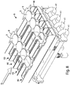
- Said application means 5 comprise a label 2 application shuttle 20 for each column of containers 3 to be labelled.
- Four shuttles 20 are provided in this embodiment, placed along a single line, each shuttle 20 having an at least partially frustum-conical shape (e.g. for 1/5 of its height), with the minor base 21 faced upward to ease insertion of the label 2 from above.
- Each shuttle 20 has a plurality of longitudinal ribs 22, creating depressions on shuttle 20 surface.
- said application means 5 comprise two transverse support elements 23 and 24 (provided transversely with respect to the linear advancement direction A), one 23 above the other 24 and spaced each other, and one or more connection means 25, in the shape of tubular elements, between said transverse support elements 23 and 24.
- Said upper transverse support element 23 is laterally coupled with motion means 6, particularly with the transmission chain 19.
- connection elements 25 are integrally coupled with the upper transverse support element 23 and sliding coupled with said lower transverse support element 24, said lower transverse support element 24 being able making a movement with respect to said upper transverse support element 23, sliding along said connection elements 25.
- said application means 5 comprise a plurality of pushing means 26, integrally coupled, in correspondence of their lower ends, with the lower transverse support element 24, thus being movable with respect to the upper transverse support element 23, the latter having said shuttles 20 integrally coupled.
- Said pushing elements 26 are provided in a group comprising two or more units, four units in this embodiment, for each shuttle 20, and every group is symmetrically provided with respect to the central axis of the relevant shuttle 20, so that, when the lower transverse support element 24 makes a movement approaching the upper transverse support element 23, each group of pushing elements 26 licks the perimeter surface of the shuttle, in correspondence of the ribs 22, said ribs 22 being in the same number of the pushing elements 26 and being realised on the surface of every shuttle 20.
- said pushing elements 26 have, in correspondence of their upper end, a projecting element or prong 27, so that when a sleeve label 2 is placed on said shuttle 20, resting on every upper end of the pushing elements 26, said prongs 27 being placed inside the label 2 to conveniently maintain the label 2 in its position.
- Said sleeve label 2 application means 5 further comprise a motion system permitting starting the movement of the lower transverse support element 24, along with the pushing elements 26, with respect to the upper transverse support element 23, and thus with respect to the shuttles 20.
- said motion system comprises a cam follower assembly. Particularly, close to one or both the lateral portions of the lower transverse support element 24 is coupled with a roll 29 permitting freely rotating about its own axis. Further, said system provides a closed (not shown) or open (as shown in figure 4 ) shaped path or cam 28, on which said roll 29 can slide. Said shaped path or cam 28 is fixed with respect to the resting plane of the machine 1, and thus it is not movable.
- prongs 27 inside perimeter of the label at the end of the lifting stroke upper profile of prongs 27 will be higher than the upper portion of the shuttle 20. This is an important feature since, for "not full body” labels, pushing elements 26 and their prongs 27 rise well beyond the upper portion of shuttles 20, until resting the upper edge of the label 2 under the horizontal flap of container 3, or in any case up to the wished height position. These positioning is obtained by a suitable vertical stroke of pushing elements 26 that obviously must be proportionate to the container 3 sizes and to the height position to be reached by the label.
- Said movement is caused by sliding of roll 29 along cam 28 against the action of return means, such as a spring 30 provided on said connection elements 25 between two transverse support elements 23 and 24.
- Spring 30 further keeps pushing plate 24 in its position also along the return path of the chain or motion means 6, where cam 28 goes without guiding the roll 29 all along the path.
- Cam 28 is only present in the label 2 lifting zone and then spring 30 brings transverse support elements 23 and 24 down, in rest position.
- Label application means 5 are moved by a linear continuous movement, passing from rest position to application position by a continuous movement.
- application means 5 After that application means 5 have brought label 2 about containers 3, application means 5 remain in the application position until when the pre-heat-shrinking step of label 2 on container 3 occurred, thus moving along with containers 3 by a continuous motion.
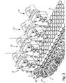
- machine 1 provides pre-heating means 7 suitable for pre-heat-shrinking of sleeve labels 2 on containers 3.
- Pre-heating means 7 are provided for each column of containers 3, four in the present embodiment.
- Said means 7, particularly shown in figures 6 and 7 comprise a pair of hollow lateral diffusers 31, provided according to a longitudinal direction with respect to the linear advancement direction A of containers 3, and in such a way to be aside said containers 3 when said containers 3 are conveyed through said pre-heating means 7.
- Said diffusers 31 have a longitudinal slot 32, advantageously provided close to the upper portion of the diffusers 31 so as to be at the same height of the upper portion of labels 2, and are connected to a relevant fluid conduct 33, e.g. hot air or vapour, provided longitudinally with respect to the advancement direction A of machine 1.
- Said conducts 33 are cantilevered above said application means 5 and under said containers' 3 transportation means 4.
- pre-heating means 7 further provide a vapour suction hood 34.
- diffusers 31 are offset and alternate each other between the container 3 columns, so that heat-shrinking of each container 3 column occurs in a different moment.
- said heat-shrinking could occur at the same time if diffusers 31 are placed side by side.
- machine 1 can provide a full heat-shrinking station 8.
- application means 5 are retracted and labels 2, rigidly coupled with containers 3, are transported by container 3 support and motion means 4, toward full heat-shrinking station 8.
- Said station 8 provides a plurality of channels 40 longitudinal with respect to the linear advancement direction A, wherein the full heat-shrinking of labels 2 on containers 3 occurs. It is provided a channel 40 for each column of container 3 - label 2 assembly.
- Said channels 40 are connected to conducts 41 within which a fluid (hot air or vapour) flows.
- Said channels 40 are so shaped to have a first inlet chamber 42 with an inlet opening 43 connected to the conduct 41, and two lateral outlet openings 44 provided in correspondence of sides of the chamber 41, transversely with respect to the sliding direction A, so as to allow the fluid exiting toward lateral walls 45 of channel 40, hitting outer sides of label 2.
- flaps 46 can be provided on a portion of walls 45 of channels 40, the inclination of which can be modified according to the needing, to make hot gas flow direction diverging toward a portion of the label 2, thus permitting a better and uniform heat-shrinking of label 2.
- said flaps 46 can be suitably shaped, inclined, ecc.
- a suction hood 47 is provided in correspondence of the upper portion of the full heat-shrinking station 8.
- Said hood 47 has the function not only of evacuating vapour, but also to direct and determine flow upward to lick container 3 surfaces. Said hood 47 is further provided with a motor controlled by a speed electronic change gear to adjust the rate.
- FIG. 10 An alternative embodiment of the labelling machine according to the invention is shown in figure 10 , wherein same components with the machine described in the above will be indicated by same reference numbers.
- Machine 1 according to the invention of figure 10 differs from machine described in the above in that sleeve label 2 supply step to label 2 application means 5 occurs in a position lateral and parallel with respect to the advancement linear direction A of containers 3.
- label supply means 12 are provided laterally with respect to the advancement linear direction A of containers 3 and label 2 application means 5 make a translational motion, particularly according to a direction diagonal with respect to the container 3 linear advancement direction A, in correspondence of said supply means 12 in order to supply labels 2 to said shuttles 20 in correspondence of said supply means 12, coming back in a position coincident with container 3 linear advancement direction A to permit supplying from the bottom said labels 2 to said containers 3.
- said application means 5 make a relative motion along relevant tracks 48, that are transversely oriented with respect to the linear advancement direction A and integral with support and motion means 6 of said application means 5, so that they pass from a label 2 supply position, in correspondence of label 2 supply means 12, to an application position in correspondence of containers 3.
- Said embodiment has the advantage of obtaining a machine with a lower height, even if wider.
Landscapes
- Labeling Devices (AREA)
Claims (19)
- Machine (1) réalisée pour appliquer des étiquettes-manchons (2) rétractables sur au moins une colonne de contenants (3) prévus les uns après les autres le long d'une direction d'avancement linéaire (A), ladite machine (1) comprenant :- des moyens d'alimentation (12) pour l'alimentation en dites étiquettes (2) des moyens pour l'application continue des mêmes étiquettes (2) sur chaque contenant (3) ;- des moyens (5) pour l'avancement continu desdits moyens d'application (5) d'étiquette (2) le long de ladite direction d'avancement linéaire (A) ;- un système (4) pour le support et le déplacement continu d'au moins une colonne de contenants (3) le long de ladite direction d'avancement linéaire (A), chaque contenant (3) étant alimenté depuis le dessus sur ledit système de support et de déplacement (4) ;- des moyens de chauffage (7, 8) pour lesdites étiquettes de manchon (2), prévus le long dudit système de support et de déplacement (4) desdits contenants (3), pour obtenir un rétrécissement partiel ou complet desdites étiquettes-manchons (2) lorsqu'elles sont appliquées sur le contenant pertinent (3) ;lesdits moyens (5) pour l'application desdites étiquettes-manchons (2) se déplaçant par lesdits moyens d'avancement (6) de sorte à amener une desdites étiquettes (2) en correspondance d'un desdits contenants (3) et étant configurés pour provoquer le déplacement vers le haut de ladite étiquette (2) par rapport au contenant pertinent (3) pour appliquer l'étiquette (2) du dessous sur le même contenant se déplaçant en continu (3) ; etlesdits moyens de chauffage (7, 8) étant configurés de sorte à activer le rétrécissement partiel ou complet desdites étiquettes (2) par rapport auxdits contenants (3) lorsque lesdites étiquettes (2) sont appliquées sur lesdits contenants (3) pendant le transport continu desdits contenants (3) par ledit système de support et de déplacement pertinent (4),dans laquelle lesdits moyens (5) pour l'application desdites étiquettes (2) comprennent une colonne de navettes (20) pour chaque colonne de contenants (3), configurée de manière à être enroulée par l'étiquette pertinente (2) lorsque lesdits moyens d'alimentation (12) ont alimenté une étiquette (2) sur les mêmes moyens de support et de poussée (26) pour ladite étiquette (2), etdes moyens de mouvement (28, 29) pour le mouvement desdits moyens de poussée (26) par rapport à ladite navette (20) pour appliquer ladite étiquette (2) sur ledit contenant (3), lesdits moyens de mouvement (28, 29) étant configurés de sorte à amener lesdits moyens d'application (5) d'une position de repos, dans laquelle ladite étiquette (2) enroule ladite navette (20) et est supportée par lesdits moyens de support et de poussée (26), dans une position d'application, dans laquelle ladite étiquette (2) enroule ledit contenant (3) et est supportée par lesdits moyens de support et de poussée (26), etdans laquelle lesdits moyens de mouvement desdits moyens d'application (5) comprennent un ensemble de came (28)-rouleau (29), dans laquelle ladite came (28) est fixée par rapport au plan restant de la machine et ledit rouleau (29) est d'un seul tenant avec lesdits moyens de poussée (26).
- Machine (1) selon la revendication précédente, caractérisée en ce que ledit système de support et de mouvement (4) pour lesdits contenants (3) comprend une pluralité d'éléments de support (9, 35) comprenant une pluralité de cavités (10, 11, 18) qui peut supporter au moins une colonne de contenants (3) dans une position verticale et prévues comme une grille, c'est-à-dire espacées les unes des autres, et placées le long de lignes et colonnes parallèles.
- Machine (1) selon la revendication précédente, caractérisée en ce que lesdits éléments de support sont des plaques (9), de préférence composées de matériau rigide, et formées de sorte à présenter une pluralité de trous (10, 11) pour le logement, de dessus, de chaque contenant (3).
- Machine (1) selon la revendication 2, caractérisée en ce que lesdits éléments de support sont des éléments transversaux (35), parallèles les uns aux autres et prévus transversalement par rapport à la direction d'avancement linéaire (A) de la machine (1), lesdits éléments transversaux (35) étant espacés les uns des autres de sorte à créer une cavité (18) pour loger une ligne de contenants (3).
- Machine (1) selon la revendication 2, caractérisée en ce que lesdits éléments de support sont composés de tapis réalisés en matériau flexible formé pour présenter une pluralité de trous pour le logement, de dessus, de chacun desdits contenants.
- Machine (1) selon l'une des revendications précédentes 2 à 5, caractérisée en ce que la surface de profil (17) de ladite pluralité de cavités (10, 11, 18) présente la portion inférieure émoussée, de préférence avec un angle de 45°.
- Machine (1) selon l'une quelconque des revendications précédentes, caractérisée en ce que lesdits moyens d'application (5) comprennent deux éléments de support transversaux (23, 24), transversalement prévus par rapport à la direction d'avancement linéaire (A), un au-dessus de l'autre, chaque navette (20) étant d'un seul tenant avec ledit élément transversal de support supérieur (23), lesdits moyens de poussée (26) étant couplés d'un seul tenant avec l'élément transversal de support inférieur (24), lesdits moyens de mouvement (28, 29) étant capables de provoquer le déplacement de l'élément transversal de support inférieur (24) par rapport à l'élément transversal de support supérieur (23) pour provoquer le déplacement vers le haut de ladite étiquette (2) par rapport au contenant (3) pour appliquer l'étiquette (2) de dessous sur le même contenant mobile (3).
- Machine (1) selon la revendication précédente, caractérisée en ce que lesdits moyens d'application (5) comprennent en outre des moyens de connexion (25) entre lesdits éléments de support transversaux (23, 24).
- Machine (1) selon l'une des revendications précédentes 7 ou 8, caractérisée en ce que lesdits moyens d'application (5) comprennent en outre des moyens de rappel (30) entre lesdits éléments de support transversaux (23, 24) dans ladite position de repos.
- Machine (1) selon l'une quelconque des revendications précédentes 7 à 9, caractérisée en ce que ledit rouleau (29) est d'un seul tenant avec ledit élément de support transversal inférieur (24).
- Machine (1) selon l'une des revendications précédentes, caractérisée en ce que lesdits moyens de chauffage peuvent comprendre des moyens de préchauffage (7) pour le rétrécissement partiel desdites étiquettes (2) sur lesdits contenants (3), et des moyens de chauffage (8), vers le bas desdits moyens de préchauffage (7), pour le rétrécissement complet desdites étiquettes (2) sur lesdits contenants (3).
- Machine (1) selon la revendication précédente, caractérisée en ce que lesdits moyens de préchauffage (7) comprennent une paire de diffuseurs creux latéraux (31), placés selon une direction longitudinale par rapport à la direction d'avancement linéaire (A), latéralement par rapport à chaque au moins une colonne de contenants (3) de sorte à être de côté desdits contenants (3) lorsque ceux-ci sont transportés à travers lesdits moyens de préchauffage (7), lesdits diffuseurs creux latéraux (31) étant dotés d'une fente longitudinale (32), ladite fente (32) étant placée de sorte à être en correspondance d'une portion desdits contenants (3) et étant reliée à un conduit (33) pour le passage d'un fluide à travers ladite fente (32) pour activer le rétrécissement thermique partiel desdites étiquettes (2) sur ladite portion desdits contenants (3).
- Machine (1) selon la revendication précédente, caractérisée en ce que, lorsque ladite machine (1) fournit deux ou plus colonnes de contenants (3), lesdits moyens de préchauffage (7) comprennent une paire de diffuseurs latéraux (31) pour chaque colonne de contenants (3), chaque paire de diffuseurs latéraux (31) étant décalée de sorte que le rétrécissement thermique partiel d'une colonne de contenants (3) se produise avant le rétrécissement thermique de la colonne adjacente.
- Machine (1) selon l'une des revendications précédentes, caractérisée en ce que lesdits moyens de chauffage comprennent des moyens de chauffage complets (8) comportant un canal longitudinal (40) par rapport à la direction d'avancement linéaire (A), pour chaque colonne de contenants (3), ledit canal longitudinal (40) étant relié à une conduite de fluide (41) et comprenant une chambre (42) avec deux ouvertures de sortie (44) pour du fluide adaptées pour diriger ledit fluide selon la direction des parois (45) dudit canal longitudinal (40) pour une distribution uniforme dudit fluide dans ledit canal (40) et pour activer le rétrécissement thermique complet de ladite étiquette (2) sur ledit contenant (3).
- Machine (1) selon la revendication précédente, caractérisée en ce que lesdites parois (45) dudit au moins un canal longitudinal (40) comprennent une portion ainsi formée pour dévier le flux du fluide vers une portion dudit contenant (3) et de ladite étiquette (2).
- Machine (1) selon l'une des revendications précédentes, caractérisée en ce que lesdits moyens de chauffage (7, 8) comprennent une hotte aspirante (34, 47).
- Machine (1) selon l'une des revendications précédentes, caractérisée en ce que lesdits moyens (12) pour l'alimentation desdites étiquettes (2) sont prévus le long de la direction d'avancement linéaire (A) desdits contenants (3).
- Machine (1) selon l'une des revendications précédentes 1 à 17, caractérisée en ce que lesdits moyens d'alimentation (12) en étiquettes (2) sont prévus latéralement par rapport à la direction d'avancement linéaire (A) desdits contenants (3) et en ce que lesdits moyens d'application (5) font un mouvement translationnel diagonal afin d'être alimentés en dites étiquettes (2) en correspondance desdits moyens d'alimentation (12) et afin d'être en correspondance desdits contenants (3) pour permettre l'application du dessous desdites étiquettes (2) sur lesdits contenants (3).
- Procédé d'application d'étiquettes-manchons rétractables (2) sur au moins une colonne de contenants (3) prévues les unes après les autres le long d'une direction d'avancement linéaire (A) au moyen de la machine selon les revendications 1-18, ledit procédé fournissant les étapes suivantes :- l'alimentation en lesdites étiquettes (2) desdits moyens (5) pour l'application continue des mêmes étiquettes (2) sur chaque contenant (3) ;- le déplacement continu par les moyens d'avancement (6) desdits moyens d'application(5) desdites étiquettes (2) le long de ladite direction d'avancement linéaire (A) ;- l'alimentation de dessus de chaque contenant (3) sur le système de support et de mouvement (4) ;- le déplacement continu par ledit système de support et de mouvement (4) d'au moins une colonne de contenants (3) le long de ladite direction d'avancement linéaire (A) ;- le déplacement continu desdits moyens d'application (5) d'étiquettes-manchons (2) par lesdits moyens d'avancement (6) de sorte à amener une desdites étiquettes (2) en correspondance d'un desdits contenants (3) ;- l'amenée du déplacement vers le haut de ladite étiquette (2) par rapport au contenant pertinent (3) à appliquer l'étiquette (2) de dessous sur le même contenant mobile (3) ;- le chauffage desdites étiquettes-manchons (2) sur lesdits contenants (3) par les moyens de chauffage (7, 8) prévus le long dudit système de support et de mouvement (4) de contenant (3), pour obtenir un rétrécissement thermique partiel ou complet desdites étiquettes-manchons (2) lorsqu'elles sont appliquées sur le contenant pertinent (3) ; et- l'activation du rétrécissement thermique partiel ou complet desdites étiquettes (2) par rapport auxdits contenants (3) lorsque lesdites étiquettes (2) sont appliquées sur lesdits contenants (3) pendant leur transport continu desdits contenants (3) par le système de support et mouvement (4) pertinent.
Applications Claiming Priority (1)
| Application Number | Priority Date | Filing Date | Title |
|---|---|---|---|
| PCT/IT2014/000220 WO2016027286A1 (fr) | 2014-08-18 | 2014-08-18 | Machine permettant d'appliquer des étiquettes-manchons rétractables et procédé d'application desdites étiquettes |
Publications (2)
| Publication Number | Publication Date |
|---|---|
| EP3183175A1 EP3183175A1 (fr) | 2017-06-28 |
| EP3183175B1 true EP3183175B1 (fr) | 2021-11-24 |
Family
ID=51900497
Family Applications (1)
| Application Number | Title | Priority Date | Filing Date |
|---|---|---|---|
| EP14799024.6A Not-in-force EP3183175B1 (fr) | 2014-08-18 | 2014-08-18 | Machine permettant d'appliquer des étiquettes-manchons rétractables et procédé d'application desdites étiquettes |
Country Status (3)
| Country | Link |
|---|---|
| EP (1) | EP3183175B1 (fr) |
| AR (1) | AR101560A1 (fr) |
| WO (1) | WO2016027286A1 (fr) |
Families Citing this family (8)
| Publication number | Priority date | Publication date | Assignee | Title |
|---|---|---|---|---|
| EP3202676A4 (fr) * | 2014-09-30 | 2018-05-16 | Fuji Seal International, Inc. | Système d'ajustement de film |
| FR3082831B1 (fr) * | 2018-06-21 | 2021-03-05 | Synerlink | Machine de pose d'etiquettes avec indexation |
| IT201900003003A1 (it) * | 2019-03-01 | 2020-09-01 | Finpac Italia S R L | Macchina e metodo per l’applicazione di etichette tubolari su contenitori |
| CN110697190B (zh) * | 2019-10-24 | 2025-01-10 | 杭州中亚机械股份有限公司 | 一种标纸供应装置 |
| CN110667966B (zh) * | 2019-10-24 | 2024-12-06 | 杭州中亚机械股份有限公司 | 一种标纸载具 |
| DE102020106384A1 (de) | 2020-03-09 | 2021-09-09 | Maier Packaging Gmbh | Vorrichtung und Verfahren zum Anbringen von Schrumpfetiketten an Behältern |
| CN113562281B (zh) * | 2021-08-30 | 2024-05-03 | 上海首颂包装机械有限公司 | 用于对不易站立的容器进行套标的套标设备及方法 |
| CN114751042A (zh) * | 2022-03-07 | 2022-07-15 | 杭州中亚机械股份有限公司 | 一种联杯产品中热缩标签的固定装置及灌装生产线 |
Family Cites Families (4)
| Publication number | Priority date | Publication date | Assignee | Title |
|---|---|---|---|---|
| ES2272948T3 (es) * | 2003-01-29 | 2007-05-01 | Benco Pack S.P.A. | Procedimiento e instalacion para aplicar una etiqueta termorretractil en recipientes. |
| ATE392302T1 (de) * | 2004-02-27 | 2008-05-15 | Hassia Verpackung Ag | Verfahren und vorrichtung zur seitenwanddekoration von verpackungsbehältnissen |
| ITRE20070082A1 (it) * | 2007-06-22 | 2008-12-23 | Benco Pack Spa | Macchina e metodo per l'etichettatura di contenitori |
| IT1395687B1 (it) * | 2009-08-03 | 2012-10-16 | Sacmi Labelling S P A Ora Sacmi Verona S P A | Dispositivo per l'applicazione di etichette termoretraibili |
-
2014
- 2014-08-18 WO PCT/IT2014/000220 patent/WO2016027286A1/fr not_active Ceased
- 2014-08-18 EP EP14799024.6A patent/EP3183175B1/fr not_active Not-in-force
-
2015
- 2015-08-14 AR ARP150102624A patent/AR101560A1/es unknown
Also Published As
| Publication number | Publication date |
|---|---|
| EP3183175A1 (fr) | 2017-06-28 |
| AR101560A1 (es) | 2016-12-28 |
| WO2016027286A1 (fr) | 2016-02-25 |
Similar Documents
| Publication | Publication Date | Title |
|---|---|---|
| WO2016027286A1 (fr) | Machine permettant d'appliquer des étiquettes-manchons rétractables et procédé d'application desdites étiquettes | |
| US8293047B2 (en) | Machine and a method for labelling containers | |
| RU2592552C2 (ru) | Конвейер для узла обработки изделий, в частности для сгибающего узла для получения упаковок с текучими пищевыми продуктами | |
| CN104822596B (zh) | 用于将打开装置施加在食物产品的密封包装件上的单元 | |
| US10486371B2 (en) | Packaging for a group of at least two containers made of plastics material | |
| CN105799139B (zh) | 一种塑料瓶自动成型液体灌装机 | |
| JP6054977B2 (ja) | 注入可能食品包装マシン用の折曲げユニット | |
| US6966166B2 (en) | High-speed continuous action form-fill-seal machine and methods | |
| US3423902A (en) | Production and filling of plastic containers | |
| US4441955A (en) | Base cup applicator | |
| US20110240588A1 (en) | Method for making containers, and corresponding container | |
| ES2823487T3 (es) | Procedimiento y máquina de ensamblaje de cuerpos tubulares rígidos hechos de material de cartón con una estructura de cierre | |
| JP5940067B2 (ja) | 容器を製造するための特に液体食品用の容器を製造するための方法および機械 | |
| JP6685931B2 (ja) | 流動食品の密封パックを供給するための供給ユニット | |
| CA2067496A1 (fr) | Dispositif de remplissage et de fermeture de contenants de liquide | |
| KR20160015547A (ko) | 프레스 절단장치를 구비한 사면 포장기 | |
| JP2011046051A (ja) | 包装袋の製造方法および製造装置 | |
| CN205572985U (zh) | 一种塑料瓶自动成型液体灌装机 | |
| US4746321A (en) | Automatic machine for forming boxes of the double-plinth type | |
| NO177694B (no) | Fremgangsmåte og anordning for oppreisning av et flatlagt, rörformet emne | |
| JP5266506B2 (ja) | 縦型複数列充填包装装置 | |
| JP4278611B2 (ja) | 容器を熱成形によって製造し該容器に装飾用バンデロールを配置するための装置 | |
| JP7383648B2 (ja) | 割出しを備えるラベル貼付機 | |
| KR200479008Y1 (ko) | 아이스크림용 튜브용기 정렬장치 | |
| ES2779625T3 (es) | Manipulador para manipular los sobrebordes de una película de plástico envuelta en torno a envases para formar un conjunto de envases, aparato que comprende tales manipuladores y método de control relativo |
Legal Events
| Date | Code | Title | Description |
|---|---|---|---|
| STAA | Information on the status of an ep patent application or granted ep patent |
Free format text: STATUS: THE INTERNATIONAL PUBLICATION HAS BEEN MADE |
|
| PUAI | Public reference made under article 153(3) epc to a published international application that has entered the european phase |
Free format text: ORIGINAL CODE: 0009012 |
|
| STAA | Information on the status of an ep patent application or granted ep patent |
Free format text: STATUS: REQUEST FOR EXAMINATION WAS MADE |
|
| 17P | Request for examination filed |
Effective date: 20170302 |
|
| AK | Designated contracting states |
Kind code of ref document: A1 Designated state(s): AL AT BE BG CH CY CZ DE DK EE ES FI FR GB GR HR HU IE IS IT LI LT LU LV MC MK MT NL NO PL PT RO RS SE SI SK SM TR |
|
| AX | Request for extension of the european patent |
Extension state: BA ME |
|
| DAX | Request for extension of the european patent (deleted) | ||
| GRAP | Despatch of communication of intention to grant a patent |
Free format text: ORIGINAL CODE: EPIDOSNIGR1 |
|
| STAA | Information on the status of an ep patent application or granted ep patent |
Free format text: STATUS: GRANT OF PATENT IS INTENDED |
|
| INTG | Intention to grant announced |
Effective date: 20210607 |
|
| GRAS | Grant fee paid |
Free format text: ORIGINAL CODE: EPIDOSNIGR3 |
|
| GRAA | (expected) grant |
Free format text: ORIGINAL CODE: 0009210 |
|
| STAA | Information on the status of an ep patent application or granted ep patent |
Free format text: STATUS: THE PATENT HAS BEEN GRANTED |
|
| AK | Designated contracting states |
Kind code of ref document: B1 Designated state(s): AL AT BE BG CH CY CZ DE DK EE ES FI FR GB GR HR HU IE IS IT LI LT LU LV MC MK MT NL NO PL PT RO RS SE SI SK SM TR |
|
| REG | Reference to a national code |
Ref country code: GB Ref legal event code: FG4D |
|
| REG | Reference to a national code |
Ref country code: AT Ref legal event code: REF Ref document number: 1449695 Country of ref document: AT Kind code of ref document: T Effective date: 20211215 |
|
| REG | Reference to a national code |
Ref country code: DE Ref legal event code: R096 Ref document number: 602014081419 Country of ref document: DE |
|
| REG | Reference to a national code |
Ref country code: IE Ref legal event code: FG4D |
|
| REG | Reference to a national code |
Ref country code: LT Ref legal event code: MG9D |
|
| REG | Reference to a national code |
Ref country code: NL Ref legal event code: MP Effective date: 20211124 |
|
| RAP4 | Party data changed (patent owner data changed or rights of a patent transferred) |
Owner name: NEWTECH S.R.L. |
|
| REG | Reference to a national code |
Ref country code: AT Ref legal event code: MK05 Ref document number: 1449695 Country of ref document: AT Kind code of ref document: T Effective date: 20211124 |
|
| PG25 | Lapsed in a contracting state [announced via postgrant information from national office to epo] |
Ref country code: RS Free format text: LAPSE BECAUSE OF FAILURE TO SUBMIT A TRANSLATION OF THE DESCRIPTION OR TO PAY THE FEE WITHIN THE PRESCRIBED TIME-LIMIT Effective date: 20211124 Ref country code: LT Free format text: LAPSE BECAUSE OF FAILURE TO SUBMIT A TRANSLATION OF THE DESCRIPTION OR TO PAY THE FEE WITHIN THE PRESCRIBED TIME-LIMIT Effective date: 20211124 Ref country code: FI Free format text: LAPSE BECAUSE OF FAILURE TO SUBMIT A TRANSLATION OF THE DESCRIPTION OR TO PAY THE FEE WITHIN THE PRESCRIBED TIME-LIMIT Effective date: 20211124 Ref country code: BG Free format text: LAPSE BECAUSE OF FAILURE TO SUBMIT A TRANSLATION OF THE DESCRIPTION OR TO PAY THE FEE WITHIN THE PRESCRIBED TIME-LIMIT Effective date: 20220224 Ref country code: AT Free format text: LAPSE BECAUSE OF FAILURE TO SUBMIT A TRANSLATION OF THE DESCRIPTION OR TO PAY THE FEE WITHIN THE PRESCRIBED TIME-LIMIT Effective date: 20211124 |
|
| REG | Reference to a national code |
Ref country code: DE Ref legal event code: R081 Ref document number: 602014081419 Country of ref document: DE Owner name: NEWTECH S.R.L., IT Free format text: FORMER OWNER: NEWTECH S.R.L., MILANO, IT |
|
| PG25 | Lapsed in a contracting state [announced via postgrant information from national office to epo] |
Ref country code: IS Free format text: LAPSE BECAUSE OF FAILURE TO SUBMIT A TRANSLATION OF THE DESCRIPTION OR TO PAY THE FEE WITHIN THE PRESCRIBED TIME-LIMIT Effective date: 20220324 Ref country code: SE Free format text: LAPSE BECAUSE OF FAILURE TO SUBMIT A TRANSLATION OF THE DESCRIPTION OR TO PAY THE FEE WITHIN THE PRESCRIBED TIME-LIMIT Effective date: 20211124 Ref country code: PT Free format text: LAPSE BECAUSE OF FAILURE TO SUBMIT A TRANSLATION OF THE DESCRIPTION OR TO PAY THE FEE WITHIN THE PRESCRIBED TIME-LIMIT Effective date: 20220324 Ref country code: PL Free format text: LAPSE BECAUSE OF FAILURE TO SUBMIT A TRANSLATION OF THE DESCRIPTION OR TO PAY THE FEE WITHIN THE PRESCRIBED TIME-LIMIT Effective date: 20211124 Ref country code: NO Free format text: LAPSE BECAUSE OF FAILURE TO SUBMIT A TRANSLATION OF THE DESCRIPTION OR TO PAY THE FEE WITHIN THE PRESCRIBED TIME-LIMIT Effective date: 20220224 Ref country code: NL Free format text: LAPSE BECAUSE OF FAILURE TO SUBMIT A TRANSLATION OF THE DESCRIPTION OR TO PAY THE FEE WITHIN THE PRESCRIBED TIME-LIMIT Effective date: 20211124 Ref country code: LV Free format text: LAPSE BECAUSE OF FAILURE TO SUBMIT A TRANSLATION OF THE DESCRIPTION OR TO PAY THE FEE WITHIN THE PRESCRIBED TIME-LIMIT Effective date: 20211124 Ref country code: HR Free format text: LAPSE BECAUSE OF FAILURE TO SUBMIT A TRANSLATION OF THE DESCRIPTION OR TO PAY THE FEE WITHIN THE PRESCRIBED TIME-LIMIT Effective date: 20211124 Ref country code: GR Free format text: LAPSE BECAUSE OF FAILURE TO SUBMIT A TRANSLATION OF THE DESCRIPTION OR TO PAY THE FEE WITHIN THE PRESCRIBED TIME-LIMIT Effective date: 20220225 Ref country code: ES Free format text: LAPSE BECAUSE OF FAILURE TO SUBMIT A TRANSLATION OF THE DESCRIPTION OR TO PAY THE FEE WITHIN THE PRESCRIBED TIME-LIMIT Effective date: 20211124 |
|
| PG25 | Lapsed in a contracting state [announced via postgrant information from national office to epo] |
Ref country code: SM Free format text: LAPSE BECAUSE OF FAILURE TO SUBMIT A TRANSLATION OF THE DESCRIPTION OR TO PAY THE FEE WITHIN THE PRESCRIBED TIME-LIMIT Effective date: 20211124 Ref country code: SK Free format text: LAPSE BECAUSE OF FAILURE TO SUBMIT A TRANSLATION OF THE DESCRIPTION OR TO PAY THE FEE WITHIN THE PRESCRIBED TIME-LIMIT Effective date: 20211124 Ref country code: RO Free format text: LAPSE BECAUSE OF FAILURE TO SUBMIT A TRANSLATION OF THE DESCRIPTION OR TO PAY THE FEE WITHIN THE PRESCRIBED TIME-LIMIT Effective date: 20211124 Ref country code: EE Free format text: LAPSE BECAUSE OF FAILURE TO SUBMIT A TRANSLATION OF THE DESCRIPTION OR TO PAY THE FEE WITHIN THE PRESCRIBED TIME-LIMIT Effective date: 20211124 Ref country code: DK Free format text: LAPSE BECAUSE OF FAILURE TO SUBMIT A TRANSLATION OF THE DESCRIPTION OR TO PAY THE FEE WITHIN THE PRESCRIBED TIME-LIMIT Effective date: 20211124 Ref country code: CZ Free format text: LAPSE BECAUSE OF FAILURE TO SUBMIT A TRANSLATION OF THE DESCRIPTION OR TO PAY THE FEE WITHIN THE PRESCRIBED TIME-LIMIT Effective date: 20211124 |
|
| REG | Reference to a national code |
Ref country code: DE Ref legal event code: R097 Ref document number: 602014081419 Country of ref document: DE |
|
| PLBE | No opposition filed within time limit |
Free format text: ORIGINAL CODE: 0009261 |
|
| STAA | Information on the status of an ep patent application or granted ep patent |
Free format text: STATUS: NO OPPOSITION FILED WITHIN TIME LIMIT |
|
| PG25 | Lapsed in a contracting state [announced via postgrant information from national office to epo] |
Ref country code: AL Free format text: LAPSE BECAUSE OF FAILURE TO SUBMIT A TRANSLATION OF THE DESCRIPTION OR TO PAY THE FEE WITHIN THE PRESCRIBED TIME-LIMIT Effective date: 20211124 |
|
| PGFP | Annual fee paid to national office [announced via postgrant information from national office to epo] |
Ref country code: IT Payment date: 20220817 Year of fee payment: 9 |
|
| 26N | No opposition filed |
Effective date: 20220825 |
|
| PG25 | Lapsed in a contracting state [announced via postgrant information from national office to epo] |
Ref country code: SI Free format text: LAPSE BECAUSE OF FAILURE TO SUBMIT A TRANSLATION OF THE DESCRIPTION OR TO PAY THE FEE WITHIN THE PRESCRIBED TIME-LIMIT Effective date: 20211124 |
|
| PG25 | Lapsed in a contracting state [announced via postgrant information from national office to epo] |
Ref country code: MC Free format text: LAPSE BECAUSE OF FAILURE TO SUBMIT A TRANSLATION OF THE DESCRIPTION OR TO PAY THE FEE WITHIN THE PRESCRIBED TIME-LIMIT Effective date: 20211124 |
|
| REG | Reference to a national code |
Ref country code: CH Ref legal event code: PL |
|
| GBPC | Gb: european patent ceased through non-payment of renewal fee |
Effective date: 20220818 |
|
| PG25 | Lapsed in a contracting state [announced via postgrant information from national office to epo] |
Ref country code: LU Free format text: LAPSE BECAUSE OF NON-PAYMENT OF DUE FEES Effective date: 20220818 Ref country code: LI Free format text: LAPSE BECAUSE OF NON-PAYMENT OF DUE FEES Effective date: 20220831 Ref country code: CH Free format text: LAPSE BECAUSE OF NON-PAYMENT OF DUE FEES Effective date: 20220831 |
|
| REG | Reference to a national code |
Ref country code: BE Ref legal event code: MM Effective date: 20220831 |
|
| PG25 | Lapsed in a contracting state [announced via postgrant information from national office to epo] |
Ref country code: IE Free format text: LAPSE BECAUSE OF NON-PAYMENT OF DUE FEES Effective date: 20220818 |
|
| PGFP | Annual fee paid to national office [announced via postgrant information from national office to epo] |
Ref country code: FR Payment date: 20230620 Year of fee payment: 10 |
|
| PG25 | Lapsed in a contracting state [announced via postgrant information from national office to epo] |
Ref country code: BE Free format text: LAPSE BECAUSE OF NON-PAYMENT OF DUE FEES Effective date: 20220831 |
|
| PG25 | Lapsed in a contracting state [announced via postgrant information from national office to epo] |
Ref country code: GB Free format text: LAPSE BECAUSE OF NON-PAYMENT OF DUE FEES Effective date: 20220818 |
|
| PGFP | Annual fee paid to national office [announced via postgrant information from national office to epo] |
Ref country code: DE Payment date: 20230620 Year of fee payment: 10 |
|
| PG25 | Lapsed in a contracting state [announced via postgrant information from national office to epo] |
Ref country code: HU Free format text: LAPSE BECAUSE OF FAILURE TO SUBMIT A TRANSLATION OF THE DESCRIPTION OR TO PAY THE FEE WITHIN THE PRESCRIBED TIME-LIMIT; INVALID AB INITIO Effective date: 20140818 |
|
| PG25 | Lapsed in a contracting state [announced via postgrant information from national office to epo] |
Ref country code: CY Free format text: LAPSE BECAUSE OF FAILURE TO SUBMIT A TRANSLATION OF THE DESCRIPTION OR TO PAY THE FEE WITHIN THE PRESCRIBED TIME-LIMIT Effective date: 20211124 |
|
| PG25 | Lapsed in a contracting state [announced via postgrant information from national office to epo] |
Ref country code: MK Free format text: LAPSE BECAUSE OF FAILURE TO SUBMIT A TRANSLATION OF THE DESCRIPTION OR TO PAY THE FEE WITHIN THE PRESCRIBED TIME-LIMIT Effective date: 20211124 |
|
| PG25 | Lapsed in a contracting state [announced via postgrant information from national office to epo] |
Ref country code: IT Free format text: LAPSE BECAUSE OF NON-PAYMENT OF DUE FEES Effective date: 20230818 |
|
| PG25 | Lapsed in a contracting state [announced via postgrant information from national office to epo] |
Ref country code: MT Free format text: LAPSE BECAUSE OF FAILURE TO SUBMIT A TRANSLATION OF THE DESCRIPTION OR TO PAY THE FEE WITHIN THE PRESCRIBED TIME-LIMIT Effective date: 20211124 |
|
| REG | Reference to a national code |
Ref country code: DE Ref legal event code: R119 Ref document number: 602014081419 Country of ref document: DE |
|
| PG25 | Lapsed in a contracting state [announced via postgrant information from national office to epo] |
Ref country code: DE Free format text: LAPSE BECAUSE OF NON-PAYMENT OF DUE FEES Effective date: 20250301 |
|
| PG25 | Lapsed in a contracting state [announced via postgrant information from national office to epo] |
Ref country code: FR Free format text: LAPSE BECAUSE OF NON-PAYMENT OF DUE FEES Effective date: 20240831 |
|
| PG25 | Lapsed in a contracting state [announced via postgrant information from national office to epo] |
Ref country code: TR Free format text: LAPSE BECAUSE OF FAILURE TO SUBMIT A TRANSLATION OF THE DESCRIPTION OR TO PAY THE FEE WITHIN THE PRESCRIBED TIME-LIMIT Effective date: 20211124 |