EP3183201B1 - Ensemble treuil et procédé d'utilisation - Google Patents
Ensemble treuil et procédé d'utilisation Download PDFInfo
- Publication number
- EP3183201B1 EP3183201B1 EP15766561.3A EP15766561A EP3183201B1 EP 3183201 B1 EP3183201 B1 EP 3183201B1 EP 15766561 A EP15766561 A EP 15766561A EP 3183201 B1 EP3183201 B1 EP 3183201B1
- Authority
- EP
- European Patent Office
- Prior art keywords
- winch
- spooling
- pedestal
- support arm
- assembly
- Prior art date
- Legal status (The legal status is an assumption and is not a legal conclusion. Google has not performed a legal analysis and makes no representation as to the accuracy of the status listed.)
- Active
Links
Images


Classifications
-
- B—PERFORMING OPERATIONS; TRANSPORTING
- B66—HOISTING; LIFTING; HAULING
- B66D—CAPSTANS; WINCHES; TACKLES, e.g. PULLEY BLOCKS; HOISTS
- B66D1/00—Rope, cable, or chain winding mechanisms; Capstans
- B66D1/28—Other constructional details
- B66D1/36—Guiding, or otherwise ensuring winding in an orderly manner, of ropes, cables, or chains
- B66D1/38—Guiding, or otherwise ensuring winding in an orderly manner, of ropes, cables, or chains by means of guides movable relative to drum or barrel
-
- B—PERFORMING OPERATIONS; TRANSPORTING
- B65—CONVEYING; PACKING; STORING; HANDLING THIN OR FILAMENTARY MATERIAL
- B65H—HANDLING THIN OR FILAMENTARY MATERIAL, e.g. SHEETS, WEBS, CABLES
- B65H2701/00—Handled material; Storage means
- B65H2701/30—Handled filamentary material
- B65H2701/35—Ropes, lines
-
- B—PERFORMING OPERATIONS; TRANSPORTING
- B65—CONVEYING; PACKING; STORING; HANDLING THIN OR FILAMENTARY MATERIAL
- B65H—HANDLING THIN OR FILAMENTARY MATERIAL, e.g. SHEETS, WEBS, CABLES
- B65H75/00—Storing webs, tapes, or filamentary material, e.g. on reels
- B65H75/02—Cores, formers, supports, or holders for coiled, wound, or folded material, e.g. reels, spindles, bobbins, cop tubes, cans, mandrels or chucks
- B65H75/34—Cores, formers, supports, or holders for coiled, wound, or folded material, e.g. reels, spindles, bobbins, cop tubes, cans, mandrels or chucks specially adapted or mounted for storing and repeatedly paying-out and re-storing lengths of material provided for particular purposes, e.g. anchored hoses, power cables
- B65H75/38—Cores, formers, supports, or holders for coiled, wound, or folded material, e.g. reels, spindles, bobbins, cop tubes, cans, mandrels or chucks specially adapted or mounted for storing and repeatedly paying-out and re-storing lengths of material provided for particular purposes, e.g. anchored hoses, power cables involving the use of a core or former internal to, and supporting, a stored package of material
- B65H75/44—Constructional details
- B65H75/4402—Guiding arrangements to control paying-out and re-storing of the material
Definitions
- the present invention relates to winch assemblies which use a winch drum motor to spool cables and other lines onto and off winch drums, and in particular to an improved spooling carriage for use in such winch assemblies. Aspects of the invention include a winch assembly including such a spooling carriage and a method of use.
- Winch assemblies are required to perform a range of tasks for example winding, reeling, spooling, lifting and lowering cable, rope, wire, umbilicals, pipes, cords, conduits or lines onto or from a reel, drum or spool.
- the reel, drum or spool typically has a central cylinder with an axis and a pair of side walls.
- winch assemblies utilise a spool guide to spool the cable onto or off the winch drum.
- the use of the spool guide mitigates problems with crushing and pinching between the spooled cable layers and facilitates the orderly spooling of cable onto or off the winch drum.
- the spool guide may mitigate uneven spooling by reducing gaps left between adjacent layers of spooled cable and also reduce the accumulation of spooled cable at the side wall of the winch drum.
- winch drum motors and winch assemblies are generally designed to tolerate heavy loads. However, winching tasks involving pulling in or paying out heavy loads at an increased fleet angle may raise sideways or lateral forces on the spool guide. If the force is excessive the spool guide may be damaged or fail.
- the range of tasks which the winch assembly may be required to perform means that the positioning and height of the winch assemblies may be required to be changed to accommodate each winching application. Constructing custom support frames and relocating a winch can be cumbersome and time consuming. Alternatively multiple winches may be provided, with each winch assigned to a specific task. However, such bespoke configurations are costly, and the footprint of multiple winches may be an issue where space is limited, such as in offshore environments.
- WO 2012/040777 A1 discloses the preamble of claims 1 and 14. JP S59 71285 U describes a winch with a support arm configured to be secured to a winch pedestal at a desired angle relative to the horizontal and/or vertical plane.
- the invention provides a spooling carriage according to claim 1 and a method of operating a winch assembly according to claim 14.
- the dependent claims provide advantageous embodiments of the invention.
- the spooling carriage By pivoting the spooling carriage relative to the hub on the winch pedestal the spooling carriage may be pivoted around the winch pedestal and may achieve a wide range of winch cable exit angles or discharge angles.
- the variable spooling carriage may facilitate the winch cable performing a range of winching tasks resulting in improved productivity and/or efficiency.
- the above invention may provide a robust, reliable and sturdy winch assembly.
- the use of at least one support arm to support the spooling carriage which is supported by the hub on the winch pedestal may facilitate the spooling carriage withstanding heavy winch loads and sideways forces.
- the winch assembly may be used to winch and/or spool a wide variety of lines, including but not limited to cable, tether, rope, wire, wire rope, umbilical, pipe, cord or conduit.
- the winch assembly preferably includes a winch drive motor.
- the winch drive motor may be configured to drive and/or rotate the winch drum on the winch pedestal about the winch axis.
- the winch drive motor may be connected to a gearbox.
- the hub on the winch pedestal may be a component of the pedestal housing or a component of a pedestal motor housing.
- the hub may comprise a spigot, and may comprise a pedestal motor housing spigot.
- the spigot may comprise any suitable shape which allows the at least one support arm to pivotally connect to the spigot and provide load bearing support to the spooling carriage.
- the spigot has a cylindrical shape.
- the spigot comprises a load bearing surface.
- the spigot may therefore be a load bearing pivot, and preferably is a load bearing pivot which is co-axial with the winch axis.
- the spigot may define a cylindrical surface located on or fixed to the winch pedestal structure which pivotally supports and provides loading bearing support to the at least one support arm.
- the support arm may comprise a support plate.
- the support plate may have an outer edge or skirt which may be upstanding from the support plate.
- the outer edge or skirt of the support plate may provide structural strength to the support arm, and may provide resistance to flexing, bending and twisting of the support arm.
- the outer edge or skirt of the support plate may prevent flexing of the support plate about an axis which intersects the plane of the edge of the support plate.
- the support plate of the support arm may provide a surface for mounting of one or more components of the winch assembly, such as a control unit. Depending on the height of the outer edge of the support arm, the edge may provide protection to components mounted on the support plate from damage.
- the support arm may have a spigot ring located at one end.
- the spigot ring may comprise a suitably sized aperture which may be configured to receive the spigot on the winch pedestal.
- the spigot ring aperture and the spigot may be dimensioned so that the spigot is pivotally received in the aperture.
- the spigot ring may be pivotally connected to the spigot and may be configured to pivot the support arms about the spigot.
- the spooling carriage is supported by two support arms. More preferably both support arms are pivotally connected to the winch pedestal via the hub.
- each load bearing support arm is pivotally connected to a spigot on the winch pedestal.
- the arrangement of a pair of parallel laterally-spaced support arms on either side of the winch pedestal provides the spooling carriage with a rigid structure which may provide strength and support to the spooling carriage against heavy winch loads and sideways forces.
- the distance between the outer surface of the winch pedestal and the inside surface of each support arm may be minimised to reduce the lateral movement of each arm relative to the winch pedestal.
- the close proximity of the support arms to the winch pedestal as the arms pivot about the hub on the winch pedestal may restrict lateral movement of the support arms and provide rigidity and strength to the support arms and the spooling carriage.
- the arrangement of the spigot ring on support arm with the spigot on the winch pedestal may be configured to transfer the load of the support arm and any load that the support arm bears from the support arm to the winch pedestal structure.
- the support arms may be configured to rotate about the spigot to align the spooling guide assembly on the spooling carriage with a predetermined desired angle relative to the horizontal and/or vertical plane.
- the support arms may be secured to the winch pedestal structure at this desired angle.
- a locking mechanism may comprise one or more securing bolts or pins to fix the support arms to the winch pedestal. Other suitable securing means may be used.
- the at least one support arm may have at least one slot or hole configured to receive the one or more securing bolt or pin.
- the winch pedestal may have at least one corresponding slot or hole configured to receive at least one securing bolt or pin, which may facilitate the at least one support arm to be secured to the winch pedestal.
- Securing the support arms to the winch pedestal may provide further rigidity to the winch structure and may provides additional support and strength to the spooling carriage. This arrangement may facilitate the spooling carriage withstanding heavy winch loads and sideways forces.
- the point at which the supporting arms are secured to winch pedestal may provide load bearing support to the support arms and spooling carriage.
- the load bearing support provided by the spigot and the locking mechanism may facilitate the spooling carriage and its support arms withstanding heavy loads and sideways forces.
- the profile shape of the at least one support arm may comprise any suitably shaped profile which allows the at least one support arm to support the spooling carriage.
- the support arm may provide lateral support to the spooling carriage and facilitate the spooling carriage withstanding heavy loads and sideways forces.
- the profile shape of the at least one support arm is a linear shape.
- the profile shape of the at least one support arm is at least a partially curved shape.
- the at least one support arm pivots through an angle of at least sixty degrees. More preferably the at least one support arm pivots through an angle of approximately ninety degrees.
- the at least one support arm pivots between an angle of approximately zero degrees and approximately one hundred and eighty degrees to the horizontal plane.
- the at least one support arm pivots between an angle of approximately zero degrees and approximately ninety degrees to the horizontal plane.
- the spooling carriage comprises a spooling guide assembly.
- the spooling assembly may comprise at least one spooling roller.
- the spooling roller may be configured to receive the line.
- the spooling guide assembly may have at least two spooling rollers.
- the spooling rollers may be configured to receive the winch line.
- the spooling guide assembly may be configured to move in a reciprocating motion, which may be in a horizontal plane.
- the spooling guide assembly is moved along a spooling shaft, which may be parallel to the winch axis.
- the spooling of the tensioned cable may be controlled and allow spooling in an orderly manner. Controlled spooling mitigates problems with crushing and pinching between the spooled cable layers as it is spooled onto or from a reel.
- the spooling carriage comprises a spooling shaft motor.
- the spooling shaft motor may be configured to move the spooling guide assembly along the spooling shaft.
- the winch assembly comprises a control unit configured to control the spooling shaft motor and/or the winch drive motor. More preferably the spooling shaft motor is controlled independently from the winch drive motor.
- control unit monitors one or more of the speed of the spooling shaft motor, the speed of the winch drum motor and/or the position of the spooling assembly.
- the control unit may be configured to position the spooling rollers and/or monitor the position the spooling rollers as they move on the spooling shaft.
- the control unit may use the winch drum rotational speed, spooling shaft motor rotational speed and/or the location or horizontal motion of the spooling guide assembly to facilitate efficient spooling.
- the control unit may also facilitate the spooling rollers being aligned with the winch line as it is spooled onto or off the winch drum to mitigate tension on the winch line between the spooling rollers and the winch drum.
- the winch assembly may comprise a second winch drive motor mounted on the drum drive shaft.
- the second winch drive motor may be used in combination with the first winch drive motor for winching/spooling heavy loads and/or lines.
- the second winch drive motor may be used as a back-up winch drum motor.
- a spooling carriage for a winch assembly comprising; a spooling guide assembly; at least one support arm to support the spooling guide carriage; wherein the at least one support arm is configured to be is pivotally connected to a winch pedestal via a hub surrounding a winch axis of the winch assembly; wherein the support arm is configured to be secured to the winch pedestal at a desired angle relative to the horizontal and/or vertical plane; and wherein the spooling guide assembly is configured to move in a reciprocating motion.
- At least one support arm to support the spooling carriage it may provide strength to the spooling carriage and may facilitate the spooling carriage withstanding heavy winch loads, side loads and/or sideways lateral forces.
- the position of the spooling guide assembly may be moved to any desired angle relative to the horizontal and/or vertical plane and fixed at that position by rotating at least one support arm about its pivot and the securing the at least one support arm at the desired angle relative to the horizontal and/or vertical plane.
- the pivot of the at least one support arm is coaxial with the winch axis.
- the spooling guide assembly comprises at least one spooling roller.
- the spooling guide assembly has at least two spooling rollers and the spooling rollers may be configured to receive a winch line therebetween.
- the spooling guide assembly may be configured to move in a reciprocating motion, which may be in a horizontal plane.
- the spooling guide assembly is moved along a spooling shaft, which may be parallel to the winch axis
- the spooling guide assembly may be driven from the winch drive motor.
- the winch drive motor may be mechanically synchronised with the spooling shaft.
- the spooling guide assembly is driven independently from the winch drive motor.
- the spooling guide assembly is driven by a spooling shaft motor.
- the spooling shaft motor may be configured to move the spooling rollers along a spooling shaft.
- a control unit may be configured to control the spooling shaft motor and the direction of travel of the spooling guide assembly along the spooling shaft.
- the control unit may be configured to position the spooling rollers and/or monitor the position the spooling rollers as they move on the spooling shaft.
- one or more sensors may be located in the spooling carriage to monitor the spooling guide assembly as it moves on the spooling shaft. At least one output signal from the one or more sensors may determine the direction that the spooling motor turns and/or the direction of travel of the guide assembly on the spooling shaft.
- the control unit may monitor the winch drum rotational speed, spooling shaft motor rotational speed and/or the location or horizontal motion of the spooling guide assembly to facilitate efficient spooling.
- the spooling carriage may comprise two support arms to support the spooling carriage. More preferably both support arms may be pivotally connected to a winch pedestal hub.
- the method may comprise driving the spooling assembly independently from the winch drive motor.
- the desired position may be any angle relative to the horizontal and/or vertical plane.
- the method may comprise securing the spooling carriage relative to the winch pedestal at the desired angle by securing the at least one support arm to the winch pedestal.
- the method may use any suitable securing means such as bolts or pins.
- the method may comprise stopping the winch drive motor and releasing the spooling carriage from the winch pedestal, rotating the spooling carriage relative to the winch axis to a second desired position and securing the spooling carriage at the second desired position.
- the method may comprise activating a winch drive motor to rotate the winch drum.
- the method may comprise moving the spooling guide assembly in a reciprocating motion, along a spooling shaft.
- the spooling shaft may be parallel to the winch axis
- the method may comprise monitoring a winch drum rotational speed to ensure that a spooling guide assembly in the spooling carriage is in the correct position to facilitate efficient spooling onto or off the winch drum.
- the method may comprise monitoring the position of the spooling guide assembly on the spooling shaft to facilitate efficient spooling onto or off the winch drum.
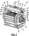
- FIG. 1 An embodiment of the present invention is illustrated in Figure 1 and provides a number of advantages over prior art winches, specifically by providing a robust and sturdy spooling carriage which is capable of being adjusted to facilitate cable exit/entry angles between approximately zero degrees and approximately ninety degrees to the horizontal plane the winch is capable of performing a wide range of winching and spooling tasks.
- FIG 1 shows a winch assembly 10 in perspective view.
- Figures 2A and 2B show the winch assembly in profile and cross-sectional views.
- the winch assembly is configured to a slightly different discharge angle compared to the discharge angle shown in Figure 1 to improve the clarity of the drawings.
- the winch assembly 10 can be seen to comprise a winch support pedestal 12 and a winch motor 14.
- the winch support pedestal 12 houses a winch drum 16 which is connected to a winch motor 14 on a winch drum drive shaft 15.
- the winch motor 14 is configured to rotate a winch drum drive shaft 15 to spool a cable 18 onto or off the winch drum 16.
- a brake assembly 17 provides braking torque to the winch drum drive shaft 15.
- the winch pedestal 12 has a bearing assembly 29 which can tolerate large axial or radial forces and may prevent the torque capacity of the winch motor 14 or brake assembly 17 being exceeded.
- a second winch motor may be located on the other end of the winch drum drive shaft 15 and may be used in combination with the first winch motor 14 to provide additional torque when winching/spooling heavy loads.
- a second brake assembly may also be located on the winch to provide additional braking torque.
- the second winch motor hub may be used as a back-up motor in the event that the first winch motor 14 fails.
- a spooling carriage 20 is attached to the winch support pedestal 12 and is supported by pivoting support arms 22 and 24 located on either side of the winch support pedestal 12.
- a benefit of providing support arms 22 and 24 is that they provide strength and support to the spooling carriage 20 and may mitigate the risk of damage or failure of the spooling carriage 20 by withstanding the stress and strains of heavy loads and sideways forces.
- the spooling carriage 20 comprises a spooling guide assembly 34 which has a spooling rollers 36 configured to receive the cable 18.
- the spooling guide assembly 34 is configured to move in a horizontal reciprocating motion along spooling shaft 38 by a spooling shaft motor 40.
- the spooling shaft motor 40 is controlled by a control unit 42 which is configured to position spooling rollers 36 in relation to the winch drum to facilitate efficient spooling.
- the control unit 42 uses feedback information relating to the winch drum rotational speed, spooling shaft motor speed and/or the location or horizontal motion of the spooling guide assembly 34 to ensure that cable is spooled onto or off the winch drum 16 in the most efficient manner.
- the control unit 42 facilitates the spooling rollers 36 being aligned with the cable 18 as it is spooled onto or off the winch drum 16 to mitigate tension on the cable 18 between the spooling rollers 36 and the winch drum 16.
- the support arms 22 and 24 have a support plate 22a and 24a with an outer edge 22b and 24b which is substantially perpendicular to the support plate 22a and 24a.
- the outer edge 22b and 24b provides structural strength to the support arm and provide resistance to flexing, bending and twisting of the support arms 22 and 24.
- the support plate 22a and 24a of the support arms 22 and 24 provides an attachment surface for mounting components of the winch assembly such as a control unit or sensors 42. Depending on the height of the outer edge, the edge may provide protection to the components located on the support plate from damage.
- the support plate 22a and 24a of the support arms 22 and 24 has a suitable width to prevent or provide resistance to bending or twisting of the support arm 22 and 24.
- this example refers to a support arm 22 and 24 having a support plate 22a and 24a with an outer edge 22b and 24b any other suitable support arm structures and dimensions is used that provide the support arm 22 and 24 with structural strength and prevent twisting, bending or flexing of the support arm 22 and 24.
- the support arms 22 and 24 have slots 28 which are configured to receive one or more securing bolts 30.
- the winch support pedestal 12 has corresponding series of holes 32 located on either side of the winch support pedestal 12.
- the securing bolts are configured to extend through the slot 28 of the support arm and to be received in the hole 32 on the winch support pedestal 12.
- the securing bolts secure the position of the supporting arms 22 and 24 to the winch support pedestal 12.
- One or more securing bolts are located in the slots 28 and holes 32 on each support arm to secure the position of the supporting arms 22 and 24 relative to the winch support pedestal 12.
- the use of securing bolts is merely an example and any other manner of securing the supporting arms 22 and 24 to the winch support pedestal 12 may be used, such as securing pins or clamps.
- Figure 3 shows an enlarged cross-sectional view of the winch to provide details on pivotally arrangement of the support arms 22 and 24 on the winch pedestal. Components of the winch and spooling carriage have been removed for clarity.
- the support arms 22 and 24 are pivotally connected to the winch pedestal 12 via pedestal motor housing spigots 19 and 21 on the winch pedestal 12.
- the spigots 19 and 21 surround the winch axis and are coaxial with the winch axis.
- spigot ring 23 At one end of the support arm 22 is located spigot ring 23.
- Spigot ring 23 has a suitably sized aperture which is configured to receive the spigot 19.
- the spigot ring 23 is pivotally connected to the spigot 19 and is configured to allow the support arms 22 to pivot about spigots 19.
- spigot ring 25 At one end of the support arm 24 is located spigot ring 25.
- Spigot ring 25 has a suitably sized aperture which is configured to receive the spigot 21.
- the spigot ring 25 is pivotally connected to the spigot 21 and is configured to allow support arm 24 to pivot about spigots 21.
- Figure 4 show a spooling carriage a cross-sectional view. The view of the spooling carriage has been enlarged and is not to scale to provide details on the structure of the spooling carriage.
- the inner surface of the distal ends of support plates 22a and 24a form the sides of the spooling carriage 20.
- the spooling carriage comprises a bar 61 which is secured between the support plate 22a and 24a of the support arms 22 and 24 and provides structural support to the spooling carriage.
- the bar 61 also provides support to the spooling guide assembly 34.
- Plates 63 (shown in Figure 1 ) extend between the outer edges 22b and 24b of the support arms 22 and 24 to provide protection to the spooling guide assembly 34 and to provide additional rigidity to the spooling carriage.
- the spooling carriage may be a separate unit which is secured to the support arms 22 and 24.
- the separate unit may be affixed to the support plates 22a and 24a or the support plate edges 22b and 24b.
- a desired exit angle or discharge angle that the cable is to exit or enter the spooling guide assembly 34 is determined.
- the spooling carriage 20 is pivoted by rotating the support arms 22 and 24 about the spigots 19 and 21 until the spooling guide assembly 34 is aligned with this predetermined desired angle.
- the spooling carriage 20 is pivoted approximately zero degrees to the horizontal plane by pivoting support arms 22 and 24 about their pivots 19 and 21.
- the support arms 22 and 24 are pivoted about spigots 19 and 21 such that the spooling carriage is positioned approximately zero degrees to the horizontal plane.
- the support arms 22 and 24 are pivotally supported by the spigots 19 and 21 on the winch pedestal.
- the load of the support arms, spooling carriage and/or cable is transferred to the winch pedestal via the support arrangement of the spigot rings 23 and 25 of support arms 22 and 23 and the spigots 19 and 21 of the winch pedestal.
- the spigots 19 and 21 provide load bearing support to the support arms 22 and 24 as the support arms pivot around the spigots 19 and 21.
- the arrangement of the pair of parallel laterally-spaced support arms 22 and 24 on either side of the winch pedestal 12 also provide the spooling carriage with a rigid structure which provides strength and support to the spooling carriage against heavy winch loads and sideways forces.
- the support arms 22 and 24 are secured at this position.
- Securing bolts 30 are positioned in slot 28 of the support arms 22 and 24 and engage bolt holes 32 on the winch pedestal 12.
- the securing bolts are configured to secure the supporting arms 22 and 24 to the winch support pedestal 12 at the desired angle.
- Securing the support arms 22 and 24 provides further rigidity to the winch structure and provides additional support and strength to the spooling carriage and facilitates the spooling carriage withstanding heavy winch loads and sideways forces against sideways forces.
- the securing bolts 30 are first removed from the holes 32 on the winch support pedestal 12 and slot 28 of the support arm 22.
- the support arms 22 and 24 of the spooling carriage 20 are pivoted about spigots 19 and 21 to position the spooling carriage 20 at a second desired angle relative to the horizontal plane.
- the load from the support arms 22 and 24 and spooling carriage 20 is transferred from the support arms 22 and 24 to the winch pedestal 14 via the arrangement of the spigot rings 23 and 25 on support arms 22 and 24 with the spigots 19 and 21 on the winch pedestal.
- the securing bolts 30 are then repositioned in slot 28 of the support arms 22 and 24 and hole 32 on the winch support pedestal 12 to secure the support arms 22 and 24 to the winch support pedestal 12 at the second angle position.
- By securing the support arms 22 and 24 to the winch pedestal provides further rigidity to the winch structure and provides additional support and strength to the spooling carriage and facilitates the spooling carriage withstanding heavy winch loads and sideways forces.
- any stress or strains applied to the winch line or spooling carriage is transferred to the winch pedestal via the support arm 22 and 24 and spigots 19 and 21.
- the arrangement of the spigot ring 23 on support arm 22 with the spigot 19 on the winch pedestal is configured to transfer the load of the support arm 22 and any load support arm bears from the support arm to the winch pedestal structure.
- the arrangement of the spigot ring 25 on support arm 24 with the spigot 21 on the winch pedestal 12 is configured to transfer the load of the support arm 24 and any load which the support arm 24 bears from the support arm 24 to the winch pedestal structure.
- the securing bolts 30 that secure the support arms 22 and 24 to bolt holes 32 on the winch pedestal 12 facilitate the transfer of load applied to the winch line or spooling carriage to the winch pedestal via the support arms. However, as the spigots also transfer a load or force applied to the winch line or spooling carriage to the winch pedestal via the support arms, the force transferred via the securing bolts may be reduced.
- the load bearing support provided by the spigots and the securing bolts 30 may enable the spooling carriage and its support arms to withstand sideways forces exposed to the spooling carriage over a wide range of cable exit/entry angles.
- the load bearing support provided by the spigots and the securing bolts 30 may enable the spooling carriage and its support arms to withstand sideways forces exposed to the spooling carriage over a wide range of cable exit/entry angles.
- the winch assembly is able to perform tasks involving pulling in or paying out heavy loads at an increased fleet angle as the sideways or lateral forces acting on the spool guide are transferred via the support arms to the winch pedestal.
- Another benefit of the improved spooling carriage is that it may improve the performance of the winch assembly by providing an independent spooling shaft motor which is controlled by a control unit.
- the control unit may monitor the rotational speed of the winch drum and the speed of movement and or location of the spooling guide assembly to ensure that the cable is spooled onto or off the winch drum in an orderly manner and mitigating cable tension and sideways forces between the spooling carriage and the winch drum.
Landscapes
- Engineering & Computer Science (AREA)
- Mechanical Engineering (AREA)
- Jib Cranes (AREA)
Claims (15)
- Un chariot d'enroulement (20) pour un ensemble de treuil (10) comprenant ;
un ensemble de guidage d'enroulement (34) ;
au moins un bras de support (22, 24) pour soutenir le chariot d'enroulement ;
dans lequel au moins un bras de support (22, 24) est configuré pour être relié de manière pivotante à un socle de treuil (12) via un moyeu entourant un axe de treuil de l'ensemble de treuil (10) ;
et dans lequel l'ensemble de guidage d'enroulement (34) est configuré pour se déplacer dans un mouvement de va-et-vient, caractérisé par le fait que le bras de support (22, 24) est configuré pour être fixé au socle de treuil (12) à l'angle souhaité par rapport au plan horizontal et/ou vertical. - Le chariot d'enroulement (20) de la revendication 1, dans lequel au moins un bras de support (22, 24) est configuré pour faire tourner le chariot d'enroulement (20) à n'importe quel angle souhaité par rapport au plan horizontal et/ou vertical.
- Le chariot d'enroulement (20) de la revendication 1 ou de la revendication 2, dans lequel l'ensemble de guidage d'enroulement (34) est entraîné indépendamment d'un moteur d'entraînement de treuil (14) par un moteur d'arbre d'enroulement (40).
- Le chariot d'enroulement (20) de la revendication 3, comprenant une unité de commande (42) configurée pour surveiller ou commander la vitesse du moteur de l'arbre d'enroulement (40), le sens de déplacement de l'ensemble de guidage d'enroulement (34) le long d'un arbre d'enroulement (38) et/ou la vitesse de rotation d'un tambour de treuil.
- Un ensemble de treuil (10) comprenant :un socle de treuil (12) ;un tambour de treuil (16) monté sur un arbre d'entraînement de tambour de treuil (15) et configuré pour être entraîné afin de tourner sur le socle de treuil (12) autour d'un axe de treuil ; etle chariot d'enroulement de l'une des revendications 1 à 4.
- L'ensemble de treuil (10) de la revendication 5, comprenant un moteur d'entraînement de treuil (14).
- L'ensemble de treuil (10) de la revendication 5 ou de la revendication 6, dans lequel le moyeu du socle de treuil (12) est un composant du boîtier du socle de treuil ou un composant du boîtier du moteur du socle de treuil.
- L'ensemble de treuil (10) de l'une des revendications 5 à 7, dans lequel le moyeu comprend un ergot (19, 21) et dans lequel l'ergot comprend une surface portante ou dans lequel l'ergot est un pivot portant qui est coaxial avec l'axe de treuil.
- L'ensemble de treuil (10) de la revendication 8, dans lequel l'ergot (19, 21) présente une forme cylindrique.
- L'ensemble de treuil (10) de l'une des revendications 5 à 9, dans lequel au moins un bras de support (22, 24) comprend une plaque de support (22a, 24a).
- L'ensemble de treuil (10) de l'une des revendications 8 à 10, dans lequel au moins un bras de support (22, 24) est configuré pour tourner autour de l'ergot (19, 21) afin de déplacer l'ensemble de guidage d'enroulement (34) sur le chariot d'enroulement (20) à l'angle souhaité prédéterminé par rapport au plan horizontal et/ou vertical.
- L'ensemble de treuil (10) de la revendication 11, dans lequel l'agencement d'une bague d'ergot sur au moins un bras de support (22, 24) avec l'ergot (19, 21) sur le socle de treuil (14) est configuré pour transférer la charge d'au moins un bras de support (22, 24) et toute charge qu'au moins un bras de support porte du bras de support (22, 24) à la structure du socle de treuil.
- L'ensemble de treuil (10) de l'une des revendications 5 à 12, dans lequel au moins un bras de support (22, 24) est configuré pour pivoter d'un angle d'au moins soixante degrés.
- Un procédé de fonctionnement d'un ensemble de treuil (10) comprenant les étapes suivantes :fournir un ensemble de treuil (10) comprenant un socle de treuil (12) ;un tambour de treuil (16) monté sur un arbre d'entraînement de tambour de treuil (15) sur un axe de treuil ;et un chariot d'enroulement (20) supporté par au moins un bras de support (22, 24), dans lequel le chariot d'enroulement (20) comprend un ensemble de guidage d'enroulement (34) configuré pour se déplacer dans un mouvement de va-et-vient ; caractérisé par les étapes consistant àfaire tourner le chariot d'enroulement (20) par rapport au socle de treuil (12) dans la position souhaitée en faisant pivoter au moins un bras de support (22, 24) autour d'un moyeu qui entoure l'axe de treuil ; etfixer le chariot d'enroulement (20) par rapport au socle de treuil (12) dans la position souhaitée.
- Le procédé de la revendication 14 comprenant les étapes suivantes :fixer le chariot d'enroulement à l'angle souhaité par rapport au socle de treuil (12) en fixant au moins un bras de support (22, 24) au socle de treuil (12) ;tirer ou dérouler un câble de treuil ; ettransférer une force latérale agissant sur le câble au socle de treuil (12) via au moins un bras de support (22, 24).
Applications Claiming Priority (2)
| Application Number | Priority Date | Filing Date | Title |
|---|---|---|---|
| GB1414739.1A GB2529433B (en) | 2014-08-19 | 2014-08-19 | Winch assembly and method of use |
| PCT/GB2015/052364 WO2016027070A1 (fr) | 2014-08-19 | 2015-08-14 | Ensemble treuil et procédé d'utilisation |
Publications (3)
| Publication Number | Publication Date |
|---|---|
| EP3183201A1 EP3183201A1 (fr) | 2017-06-28 |
| EP3183201B1 true EP3183201B1 (fr) | 2021-03-10 |
| EP3183201B8 EP3183201B8 (fr) | 2021-06-16 |
Family
ID=51662668
Family Applications (1)
| Application Number | Title | Priority Date | Filing Date |
|---|---|---|---|
| EP15766561.3A Not-in-force EP3183201B8 (fr) | 2014-08-19 | 2015-08-14 | Ensemble treuil et procédé d'utilisation |
Country Status (6)
| Country | Link |
|---|---|
| US (1) | US20180229983A1 (fr) |
| EP (1) | EP3183201B8 (fr) |
| DK (1) | DK3183201T3 (fr) |
| GB (1) | GB2529433B (fr) |
| SG (1) | SG11201701199VA (fr) |
| WO (1) | WO2016027070A1 (fr) |
Families Citing this family (8)
| Publication number | Priority date | Publication date | Assignee | Title |
|---|---|---|---|---|
| US10233705B2 (en) | 2015-07-17 | 2019-03-19 | PATCO Machine & Fab., Inc. | Reel control systems with data logging |
| US10865068B2 (en) | 2019-04-23 | 2020-12-15 | PATCO Machine & Fab., Inc. | Electronically controlled reel systems including electric motors |
| CN107697689B (zh) * | 2017-07-03 | 2019-03-01 | 嘉善兴茂毛纺织染整有限公司 | 一种能实现卷布以及放布的纺织装置 |
| US20190161315A1 (en) * | 2017-11-29 | 2019-05-30 | Cameron International Corporation | Controlled rotational measuring head and spooling system for strings configured to deliver and retrieve downhole tools and method of its use |
| CN108408621B (zh) * | 2018-03-30 | 2019-10-18 | 宁波联达绞盘有限公司 | 绞盘 |
| US11174122B2 (en) | 2018-04-23 | 2021-11-16 | PATCO Machine & Fab., Inc. | Reel with power advance repositionable level wind |
| USD943233S1 (en) * | 2020-02-10 | 2022-02-08 | Dalext Products Pty Ltd | Winch |
| US12234130B2 (en) * | 2020-10-09 | 2025-02-25 | Warn Industries, Inc. | Fairlead with integrated positioning device |
Family Cites Families (27)
| Publication number | Priority date | Publication date | Assignee | Title |
|---|---|---|---|---|
| US959621A (en) * | 1908-08-11 | 1910-05-31 | Jeffrey Mfg Co | Cable-reeling mechanism for electric locomotives. |
| US1946920A (en) * | 1933-06-23 | 1934-02-13 | Columbus Mckinnon Chain Compan | Means for controlling the slack of cables |
| US3176931A (en) * | 1962-02-02 | 1965-04-06 | Clifford B Haunay & Son Inc | Static grounding reels |
| US3552682A (en) * | 1968-10-22 | 1971-01-05 | Breeze Corp | Level wind device |
| US3533575A (en) * | 1968-11-07 | 1970-10-13 | Breeze Corp | Intermittent level wind |
| US3645503A (en) * | 1970-08-13 | 1972-02-29 | Superwich Inc | Cable control unit |
| GB1486056A (en) * | 1974-06-11 | 1977-09-14 | Ferodo Sa | Winding cables and the like on to storage drums |
| US4083510A (en) * | 1976-06-14 | 1978-04-11 | Mccaffrey-Ruddock Tagline Corporation | Self-adjusting fairlead for spring rewound tagline device |
| JPS583958B2 (ja) * | 1979-01-17 | 1983-01-24 | 大洋船具株式会社 | ウインチ装置 |
| FI64254C (fi) * | 1981-07-03 | 1983-10-10 | Perusyhtyme Oy | Kabeluppsamlingssystem foer el-drivna gruvfordon och arbetsmaskiner |
| JPS5971285U (ja) * | 1982-11-02 | 1984-05-15 | 株式会社小松製作所 | ウインチの乱巻防止装置 |
| US4552340A (en) * | 1983-09-29 | 1985-11-12 | True Dimension Inc. | Portable winch |
| US4767073A (en) * | 1984-09-10 | 1988-08-30 | Malzacher Fred H | Cable spooling system |
| US4666102A (en) * | 1985-09-23 | 1987-05-19 | Westinghouse Electric Corp. | Cable dispensing and take-up apparatus |
| GB9623713D0 (en) * | 1996-11-14 | 1997-01-08 | Hartley Brian | Semi-automatic electric cable extension reel |
| CA2227801A1 (fr) * | 1997-03-15 | 1998-09-15 | Theodor Kromer Gmbh Unternehmensgruppe Unican | Dispositif d'egalisation du poids d'une charge suspendue |
| US5950953A (en) * | 1998-01-27 | 1999-09-14 | Benton F. Baugh | Reel with adjustable fleet angle |
| KR20050035346A (ko) * | 2003-10-13 | 2005-04-18 | 협우물산 주식회사 | 호스 자동 감김 및 인출장치를 갖는 생력형 방제시스템 |
| US7210647B2 (en) * | 2005-05-23 | 2007-05-01 | Patco Machine And Fabricating, Inc. | Reel with level winding mechanism |
| GB0714880D0 (en) * | 2007-07-31 | 2007-09-12 | Expro North Sea Ltd | Winch assembly |
| GB0722581D0 (en) * | 2007-11-16 | 2007-12-27 | Brown Ian A | Auto-Guide |
| US9248999B2 (en) * | 2009-09-25 | 2016-02-02 | Harry Xydias | Level wind arm for a winch assembly |
| CN102753462A (zh) * | 2010-01-14 | 2012-10-24 | 格瑞克明尼苏达有限公司 | 软管卷盘卷轴 |
| AU2010224459B2 (en) * | 2010-09-29 | 2016-05-05 | Harry Xydias | Level wind assembly for a winch drum including a tensioning arm |
| US8061644B1 (en) * | 2011-01-12 | 2011-11-22 | PATCO Machine & Fab., Inc. | Incrementally adjustable level winding mechanism |
| EP2921448B1 (fr) * | 2014-03-18 | 2016-05-18 | ABB Technology Oy | Procédé pour faire fonctionner un treuil et treuil |
| US9689437B1 (en) * | 2016-06-23 | 2017-06-27 | Premier Coil Solutions, Inc. | Clutch mechanism |
-
2014
- 2014-08-19 GB GB1414739.1A patent/GB2529433B/en not_active Expired - Fee Related
-
2015
- 2015-08-14 DK DK15766561.3T patent/DK3183201T3/da active
- 2015-08-14 US US15/504,261 patent/US20180229983A1/en not_active Abandoned
- 2015-08-14 WO PCT/GB2015/052364 patent/WO2016027070A1/fr not_active Ceased
- 2015-08-14 SG SG11201701199VA patent/SG11201701199VA/en unknown
- 2015-08-14 EP EP15766561.3A patent/EP3183201B8/fr not_active Not-in-force
Non-Patent Citations (1)
| Title |
|---|
| None * |
Also Published As
| Publication number | Publication date |
|---|---|
| GB2529433B (en) | 2017-04-05 |
| GB201414739D0 (en) | 2014-10-01 |
| WO2016027070A1 (fr) | 2016-02-25 |
| EP3183201B8 (fr) | 2021-06-16 |
| US20180229983A1 (en) | 2018-08-16 |
| GB2529433A (en) | 2016-02-24 |
| SG11201701199VA (en) | 2017-03-30 |
| DK3183201T3 (da) | 2021-06-14 |
| EP3183201A1 (fr) | 2017-06-28 |
Similar Documents
| Publication | Publication Date | Title |
|---|---|---|
| EP3183201B1 (fr) | Ensemble treuil et procédé d'utilisation | |
| AU2011234316B2 (en) | Winch apparatus | |
| JP7362739B2 (ja) | ロープガイド装置、電動巻上機及びクレーンシステム | |
| US10351396B2 (en) | Apparatus and method for replacing cable or wire in a hoisting system | |
| WO2012128637A1 (fr) | Dispositif pour serrer une corde | |
| EP2363624B1 (fr) | Mécanisme de palier pour bobine de conduit aérien | |
| WO2009028932A1 (fr) | Dispositif de déplacement axial, système de déploiement de corde, et procédé de déploiement d'une corde | |
| CA2798576C (fr) | Dispositif de guidage de cable pour un treuil a cable | |
| EP3197808B1 (fr) | Ensemble d'entraînement de bobine | |
| CN113614019A (zh) | 绞车的绳引导装置 | |
| CN113697701A (zh) | 卷筒、起升机构及升降机 | |
| CN104743463B (zh) | 一种钢丝绳保护装置及具有其的旋挖钻机 | |
| CN224105468U (zh) | 起吊装置及天车 | |
| EP4480883A1 (fr) | Gestion de câble de grue et de tuyau | |
| CN222846226U (zh) | 一种管材收放管拖车 | |
| KR20090012275U (ko) | 와이어 로프 교체용 가이드 장치 | |
| EP2872439B1 (fr) | Ensemble treuil marin | |
| KR20180026110A (ko) | 케이블 드럼용 지그 | |
| KR20250169562A (ko) | 기초 파일 위치 결정 시스템 | |
| KR20130003981U (ko) | 파이프 조립용 회전장치 | |
| JPH10218573A (ja) | 燃料取扱機の主ホイスト巻上機 |
Legal Events
| Date | Code | Title | Description |
|---|---|---|---|
| STAA | Information on the status of an ep patent application or granted ep patent |
Free format text: STATUS: THE INTERNATIONAL PUBLICATION HAS BEEN MADE |
|
| PUAI | Public reference made under article 153(3) epc to a published international application that has entered the european phase |
Free format text: ORIGINAL CODE: 0009012 |
|
| STAA | Information on the status of an ep patent application or granted ep patent |
Free format text: STATUS: REQUEST FOR EXAMINATION WAS MADE |
|
| 17P | Request for examination filed |
Effective date: 20170313 |
|
| AK | Designated contracting states |
Kind code of ref document: A1 Designated state(s): AL AT BE BG CH CY CZ DE DK EE ES FI FR GB GR HR HU IE IS IT LI LT LU LV MC MK MT NL NO PL PT RO RS SE SI SK SM TR |
|
| AX | Request for extension of the european patent |
Extension state: BA ME |
|
| DAV | Request for validation of the european patent (deleted) | ||
| DAX | Request for extension of the european patent (deleted) | ||
| GRAP | Despatch of communication of intention to grant a patent |
Free format text: ORIGINAL CODE: EPIDOSNIGR1 |
|
| STAA | Information on the status of an ep patent application or granted ep patent |
Free format text: STATUS: GRANT OF PATENT IS INTENDED |
|
| INTG | Intention to grant announced |
Effective date: 20201005 |
|
| GRAS | Grant fee paid |
Free format text: ORIGINAL CODE: EPIDOSNIGR3 |
|
| GRAA | (expected) grant |
Free format text: ORIGINAL CODE: 0009210 |
|
| STAA | Information on the status of an ep patent application or granted ep patent |
Free format text: STATUS: THE PATENT HAS BEEN GRANTED |
|
| AK | Designated contracting states |
Kind code of ref document: B1 Designated state(s): AL AT BE BG CH CY CZ DE DK EE ES FI FR GB GR HR HU IE IS IT LI LT LU LV MC MK MT NL NO PL PT RO RS SE SI SK SM TR |
|
| REG | Reference to a national code |
Ref country code: GB Ref legal event code: FG4D |
|
| REG | Reference to a national code |
Ref country code: AT Ref legal event code: REF Ref document number: 1369631 Country of ref document: AT Kind code of ref document: T Effective date: 20210315 Ref country code: CH Ref legal event code: EP |
|
| REG | Reference to a national code |
Ref country code: IE Ref legal event code: FG4D |
|
| REG | Reference to a national code |
Ref country code: DE Ref legal event code: R096 Ref document number: 602015066677 Country of ref document: DE |
|
| RBV | Designated contracting states (corrected) |
Designated state(s): AL AT BE BG CH CY CZ DE DK EE ES FI FR GR HR HU IE IS IT LI LT LU LV MC MK MT NL NO PL PT RO RS SE SI SK SM TR |
|
| REG | Reference to a national code |
Ref country code: NL Ref legal event code: FP |
|
| REG | Reference to a national code |
Ref country code: CH Ref legal event code: PK Free format text: BERICHTIGUNG B8 |
|
| REG | Reference to a national code |
Ref country code: DK Ref legal event code: T3 Effective date: 20210607 |
|
| REG | Reference to a national code |
Ref country code: LT Ref legal event code: MG9D |
|
| PG25 | Lapsed in a contracting state [announced via postgrant information from national office to epo] |
Ref country code: LT Free format text: LAPSE BECAUSE OF FAILURE TO SUBMIT A TRANSLATION OF THE DESCRIPTION OR TO PAY THE FEE WITHIN THE PRESCRIBED TIME-LIMIT Effective date: 20210310 Ref country code: GR Free format text: LAPSE BECAUSE OF FAILURE TO SUBMIT A TRANSLATION OF THE DESCRIPTION OR TO PAY THE FEE WITHIN THE PRESCRIBED TIME-LIMIT Effective date: 20210611 Ref country code: HR Free format text: LAPSE BECAUSE OF FAILURE TO SUBMIT A TRANSLATION OF THE DESCRIPTION OR TO PAY THE FEE WITHIN THE PRESCRIBED TIME-LIMIT Effective date: 20210310 Ref country code: FI Free format text: LAPSE BECAUSE OF FAILURE TO SUBMIT A TRANSLATION OF THE DESCRIPTION OR TO PAY THE FEE WITHIN THE PRESCRIBED TIME-LIMIT Effective date: 20210310 Ref country code: BG Free format text: LAPSE BECAUSE OF FAILURE TO SUBMIT A TRANSLATION OF THE DESCRIPTION OR TO PAY THE FEE WITHIN THE PRESCRIBED TIME-LIMIT Effective date: 20210610 |
|
| REG | Reference to a national code |
Ref country code: AT Ref legal event code: MK05 Ref document number: 1369631 Country of ref document: AT Kind code of ref document: T Effective date: 20210310 |
|
| REG | Reference to a national code |
Ref country code: NO Ref legal event code: T2 Effective date: 20210310 |
|
| PG25 | Lapsed in a contracting state [announced via postgrant information from national office to epo] |
Ref country code: SE Free format text: LAPSE BECAUSE OF FAILURE TO SUBMIT A TRANSLATION OF THE DESCRIPTION OR TO PAY THE FEE WITHIN THE PRESCRIBED TIME-LIMIT Effective date: 20210310 Ref country code: LV Free format text: LAPSE BECAUSE OF FAILURE TO SUBMIT A TRANSLATION OF THE DESCRIPTION OR TO PAY THE FEE WITHIN THE PRESCRIBED TIME-LIMIT Effective date: 20210310 Ref country code: RS Free format text: LAPSE BECAUSE OF FAILURE TO SUBMIT A TRANSLATION OF THE DESCRIPTION OR TO PAY THE FEE WITHIN THE PRESCRIBED TIME-LIMIT Effective date: 20210310 |
|
| PG25 | Lapsed in a contracting state [announced via postgrant information from national office to epo] |
Ref country code: CZ Free format text: LAPSE BECAUSE OF FAILURE TO SUBMIT A TRANSLATION OF THE DESCRIPTION OR TO PAY THE FEE WITHIN THE PRESCRIBED TIME-LIMIT Effective date: 20210310 Ref country code: EE Free format text: LAPSE BECAUSE OF FAILURE TO SUBMIT A TRANSLATION OF THE DESCRIPTION OR TO PAY THE FEE WITHIN THE PRESCRIBED TIME-LIMIT Effective date: 20210310 Ref country code: AT Free format text: LAPSE BECAUSE OF FAILURE TO SUBMIT A TRANSLATION OF THE DESCRIPTION OR TO PAY THE FEE WITHIN THE PRESCRIBED TIME-LIMIT Effective date: 20210310 Ref country code: SM Free format text: LAPSE BECAUSE OF FAILURE TO SUBMIT A TRANSLATION OF THE DESCRIPTION OR TO PAY THE FEE WITHIN THE PRESCRIBED TIME-LIMIT Effective date: 20210310 |
|
| PG25 | Lapsed in a contracting state [announced via postgrant information from national office to epo] |
Ref country code: PT Free format text: LAPSE BECAUSE OF FAILURE TO SUBMIT A TRANSLATION OF THE DESCRIPTION OR TO PAY THE FEE WITHIN THE PRESCRIBED TIME-LIMIT Effective date: 20210712 Ref country code: PL Free format text: LAPSE BECAUSE OF FAILURE TO SUBMIT A TRANSLATION OF THE DESCRIPTION OR TO PAY THE FEE WITHIN THE PRESCRIBED TIME-LIMIT Effective date: 20210310 Ref country code: SK Free format text: LAPSE BECAUSE OF FAILURE TO SUBMIT A TRANSLATION OF THE DESCRIPTION OR TO PAY THE FEE WITHIN THE PRESCRIBED TIME-LIMIT Effective date: 20210310 Ref country code: RO Free format text: LAPSE BECAUSE OF FAILURE TO SUBMIT A TRANSLATION OF THE DESCRIPTION OR TO PAY THE FEE WITHIN THE PRESCRIBED TIME-LIMIT Effective date: 20210310 Ref country code: IS Free format text: LAPSE BECAUSE OF FAILURE TO SUBMIT A TRANSLATION OF THE DESCRIPTION OR TO PAY THE FEE WITHIN THE PRESCRIBED TIME-LIMIT Effective date: 20210710 |
|
| REG | Reference to a national code |
Ref country code: DE Ref legal event code: R097 Ref document number: 602015066677 Country of ref document: DE |
|
| PLBE | No opposition filed within time limit |
Free format text: ORIGINAL CODE: 0009261 |
|
| STAA | Information on the status of an ep patent application or granted ep patent |
Free format text: STATUS: NO OPPOSITION FILED WITHIN TIME LIMIT |
|
| PG25 | Lapsed in a contracting state [announced via postgrant information from national office to epo] |
Ref country code: ES Free format text: LAPSE BECAUSE OF FAILURE TO SUBMIT A TRANSLATION OF THE DESCRIPTION OR TO PAY THE FEE WITHIN THE PRESCRIBED TIME-LIMIT Effective date: 20210310 Ref country code: AL Free format text: LAPSE BECAUSE OF FAILURE TO SUBMIT A TRANSLATION OF THE DESCRIPTION OR TO PAY THE FEE WITHIN THE PRESCRIBED TIME-LIMIT Effective date: 20210310 |
|
| 26N | No opposition filed |
Effective date: 20211213 |
|
| PG25 | Lapsed in a contracting state [announced via postgrant information from national office to epo] |
Ref country code: SI Free format text: LAPSE BECAUSE OF FAILURE TO SUBMIT A TRANSLATION OF THE DESCRIPTION OR TO PAY THE FEE WITHIN THE PRESCRIBED TIME-LIMIT Effective date: 20210310 |
|
| REG | Reference to a national code |
Ref country code: CH Ref legal event code: PL |
|
| PG25 | Lapsed in a contracting state [announced via postgrant information from national office to epo] |
Ref country code: MC Free format text: LAPSE BECAUSE OF FAILURE TO SUBMIT A TRANSLATION OF THE DESCRIPTION OR TO PAY THE FEE WITHIN THE PRESCRIBED TIME-LIMIT Effective date: 20210310 |
|
| REG | Reference to a national code |
Ref country code: BE Ref legal event code: MM Effective date: 20210831 |
|
| PG25 | Lapsed in a contracting state [announced via postgrant information from national office to epo] |
Ref country code: LI Free format text: LAPSE BECAUSE OF NON-PAYMENT OF DUE FEES Effective date: 20210831 Ref country code: IT Free format text: LAPSE BECAUSE OF FAILURE TO SUBMIT A TRANSLATION OF THE DESCRIPTION OR TO PAY THE FEE WITHIN THE PRESCRIBED TIME-LIMIT Effective date: 20210310 Ref country code: CH Free format text: LAPSE BECAUSE OF NON-PAYMENT OF DUE FEES Effective date: 20210831 |
|
| PG25 | Lapsed in a contracting state [announced via postgrant information from national office to epo] |
Ref country code: IS Free format text: LAPSE BECAUSE OF FAILURE TO SUBMIT A TRANSLATION OF THE DESCRIPTION OR TO PAY THE FEE WITHIN THE PRESCRIBED TIME-LIMIT Effective date: 20210710 Ref country code: LU Free format text: LAPSE BECAUSE OF NON-PAYMENT OF DUE FEES Effective date: 20210814 |
|
| PG25 | Lapsed in a contracting state [announced via postgrant information from national office to epo] |
Ref country code: IE Free format text: LAPSE BECAUSE OF NON-PAYMENT OF DUE FEES Effective date: 20210814 Ref country code: BE Free format text: LAPSE BECAUSE OF NON-PAYMENT OF DUE FEES Effective date: 20210831 |
|
| PG25 | Lapsed in a contracting state [announced via postgrant information from national office to epo] |
Ref country code: HU Free format text: LAPSE BECAUSE OF FAILURE TO SUBMIT A TRANSLATION OF THE DESCRIPTION OR TO PAY THE FEE WITHIN THE PRESCRIBED TIME-LIMIT; INVALID AB INITIO Effective date: 20150814 |
|
| PG25 | Lapsed in a contracting state [announced via postgrant information from national office to epo] |
Ref country code: CY Free format text: LAPSE BECAUSE OF FAILURE TO SUBMIT A TRANSLATION OF THE DESCRIPTION OR TO PAY THE FEE WITHIN THE PRESCRIBED TIME-LIMIT Effective date: 20210310 |
|
| P01 | Opt-out of the competence of the unified patent court (upc) registered |
Effective date: 20230529 |
|
| PGFP | Annual fee paid to national office [announced via postgrant information from national office to epo] |
Ref country code: NL Payment date: 20230826 Year of fee payment: 9 |
|
| PGFP | Annual fee paid to national office [announced via postgrant information from national office to epo] |
Ref country code: NO Payment date: 20230807 Year of fee payment: 9 |
|
| PGFP | Annual fee paid to national office [announced via postgrant information from national office to epo] |
Ref country code: FR Payment date: 20230807 Year of fee payment: 9 Ref country code: DK Payment date: 20230804 Year of fee payment: 9 Ref country code: DE Payment date: 20230831 Year of fee payment: 9 |
|
| PG25 | Lapsed in a contracting state [announced via postgrant information from national office to epo] |
Ref country code: MK Free format text: LAPSE BECAUSE OF FAILURE TO SUBMIT A TRANSLATION OF THE DESCRIPTION OR TO PAY THE FEE WITHIN THE PRESCRIBED TIME-LIMIT Effective date: 20210310 |
|
| PG25 | Lapsed in a contracting state [announced via postgrant information from national office to epo] |
Ref country code: MT Free format text: LAPSE BECAUSE OF FAILURE TO SUBMIT A TRANSLATION OF THE DESCRIPTION OR TO PAY THE FEE WITHIN THE PRESCRIBED TIME-LIMIT Effective date: 20210310 |
|
| REG | Reference to a national code |
Ref country code: DE Ref legal event code: R119 Ref document number: 602015066677 Country of ref document: DE |
|
| REG | Reference to a national code |
Ref country code: DK Ref legal event code: EBP Effective date: 20240831 |
|
| REG | Reference to a national code |
Ref country code: NL Ref legal event code: MM Effective date: 20240901 |
|
| PG25 | Lapsed in a contracting state [announced via postgrant information from national office to epo] |
Ref country code: NO Free format text: LAPSE BECAUSE OF NON-PAYMENT OF DUE FEES Effective date: 20240831 |
|
| PG25 | Lapsed in a contracting state [announced via postgrant information from national office to epo] |
Ref country code: NL Free format text: LAPSE BECAUSE OF NON-PAYMENT OF DUE FEES Effective date: 20240901 |
|
| PG25 | Lapsed in a contracting state [announced via postgrant information from national office to epo] |
Ref country code: DE Free format text: LAPSE BECAUSE OF NON-PAYMENT OF DUE FEES Effective date: 20250301 |
|
| PG25 | Lapsed in a contracting state [announced via postgrant information from national office to epo] |
Ref country code: DK Free format text: LAPSE BECAUSE OF NON-PAYMENT OF DUE FEES Effective date: 20240831 |
|
| PG25 | Lapsed in a contracting state [announced via postgrant information from national office to epo] |
Ref country code: FR Free format text: LAPSE BECAUSE OF NON-PAYMENT OF DUE FEES Effective date: 20240831 |
|
| PG25 | Lapsed in a contracting state [announced via postgrant information from national office to epo] |
Ref country code: TR Free format text: LAPSE BECAUSE OF FAILURE TO SUBMIT A TRANSLATION OF THE DESCRIPTION OR TO PAY THE FEE WITHIN THE PRESCRIBED TIME-LIMIT Effective date: 20210310 |