EP3183995A1 - Structure de cadre pour realiser un arrangement de meubles - Google Patents
Structure de cadre pour realiser un arrangement de meubles Download PDFInfo
- Publication number
- EP3183995A1 EP3183995A1 EP16205807.7A EP16205807A EP3183995A1 EP 3183995 A1 EP3183995 A1 EP 3183995A1 EP 16205807 A EP16205807 A EP 16205807A EP 3183995 A1 EP3183995 A1 EP 3183995A1
- Authority
- EP
- European Patent Office
- Prior art keywords
- frame
- furniture
- elements
- arrangement
- subframe
- Prior art date
- Legal status (The legal status is an assumption and is not a legal conclusion. Google has not performed a legal analysis and makes no representation as to the accuracy of the status listed.)
- Granted
Links
Images
















Classifications
-
- A—HUMAN NECESSITIES
- A47—FURNITURE; DOMESTIC ARTICLES OR APPLIANCES; COFFEE MILLS; SPICE MILLS; SUCTION CLEANERS IN GENERAL
- A47B—TABLES; DESKS; OFFICE FURNITURE; CABINETS; DRAWERS; GENERAL DETAILS OF FURNITURE
- A47B77/00—Kitchen cabinets
-
- A—HUMAN NECESSITIES
- A47—FURNITURE; DOMESTIC ARTICLES OR APPLIANCES; COFFEE MILLS; SPICE MILLS; SUCTION CLEANERS IN GENERAL
- A47B—TABLES; DESKS; OFFICE FURNITURE; CABINETS; DRAWERS; GENERAL DETAILS OF FURNITURE
- A47B96/00—Details of cabinets, racks or shelf units not covered by a single one of groups A47B43/00 - A47B95/00; General details of furniture
- A47B96/20—Furniture panels or like furniture elements
- A47B96/205—Composite panels, comprising several elements joined together
-
- A—HUMAN NECESSITIES
- A47—FURNITURE; DOMESTIC ARTICLES OR APPLIANCES; COFFEE MILLS; SPICE MILLS; SUCTION CLEANERS IN GENERAL
- A47B—TABLES; DESKS; OFFICE FURNITURE; CABINETS; DRAWERS; GENERAL DETAILS OF FURNITURE
- A47B2230/00—Furniture jointing; Furniture with such jointing
- A47B2230/0055—Biscuits including formed staples or the like
- A47B2230/0062—Connectors for adjacent furniture parts, the mouths of the grooves for said connectors being on the join lines of said furniture parts
Definitions
- the present invention relates to a frame structure for constructing a furniture assembly, a method for constructing a furniture assembly having a plurality of individual cuboid furniture bodies in a predetermined space, preferably a kitchen, and a computer program product for carrying out the method.
- DE 1 941 797 U1 describes a modular assembly kitchen equipment consisting of known furniture, such as half-height standing on the floor, hanging and vertical pieces of furniture that are suitable for receiving household electrical appliances, both a one-piece piece of furniture as well as several pieces of furniture of the same kind, the assembled into a single whole may consist of what can be achieved by the assembly of various prefabricated and standardized parts, consisting of metal uprights, which have a longitudinally extending groove, fixed shelves connectable to the uprights, back walls and standardized elements for the casing and for forming inner partitions of the furniture and height-adjustable shelves and Flaps, and being provided for press-fitting of the standardized parts fasteners and small, provided with guides and supports for drawers frame, which can be set between the fixed shelves of the half-height standing on the floor and vertical furniture as desired, and wherein in the stands holes for Receiving the connecting elements are provided and arranged so that at least the rear walls forming elements, the flaps and the boxes carrying the drawers are interchangeable as desired and required.
- DE 200 00 640 U1 describes a piece of furniture made of modular elements, which is designed specifically for kitchen and other household furniture pieces, the piece of furniture having side walls with solid elements which are coupled by connected to the side walls side members, and wherein at least one connected to the side members bottom part and with the side rails coupled plates are provided.
- kitchen furniture usually consist of Korpi individual, which can be combined and connected differently depending on needs.
- the areas that separate the Korpi from each other double, because each body has its own outer panels. This requires a large number of individual plates.
- the Korpi are usually assembled before they are transported to the customer and assembled there to the finished kitchen. Both the packing mass to be transported and the volume are therefore relatively large.
- the Korpi for water and electrical installations or the like may have to be sawed again after assembly, which means additional effort.
- each body When mounting at the customer, each body must be individually aligned before the Korpi are bolted together. If necessary, the feet of Korpi must then be readjusted again. As a result, the assembly is very time consuming.
- An object of the present invention is therefore to provide a structure and a method which makes it possible to produce a furniture assembly quickly and easily, individually and flexibly adapt to a given space and to assemble there.
- the frame structure according to the invention for constructing a furniture assembly comprises a plurality of frame elements formed as longitudinal elements, which completely comprise a base surface arrangement composed of two or more rectangular subframe surfaces and subdivide the base surface arrangement into the two or more subframe surfaces; wherein at least two of the sub-frame surfaces are connected to each other by one or more common frame members, such that they have a common side, and wherein on at least one frame member of the plurality of frame members extending in the longitudinal direction of the frame member groove profile is formed for insertion of at least one surface element in such a way that the inserted surface element is oriented substantially perpendicular to the relevant subframe surface of the base surface arrangement, which is framed by the at least one frame element.
- a basic idea of the invention is to construct a furniture arrangement comprising a plurality of furniture corps in such a way that it is constructed using the frame structure according to the invention, this furnishing a separate subframe for each individual furniture body.
- the sum of the sub-frame forms the base surface arrangement, in other words the base of the entire furniture assembly.
- the furniture corps are then constructed by inserting surface elements. This is done using the frame elements according to the invention, which allow due to the groove profile insertion of the surface elements in a simple manner to build the furniture Korpi most efficient in a parallel structure. It is advantageous, but not necessarily so that several subframes are related to common frame elements by having a common side.
- a kitchenette can be constructed; a subframe spaced therefrom can serve for example to build up an additional wall unit carcass.
- both the frame elements themselves and the surface elements of the furniture assembly can be prefabricated in large numbers and later individually adapted to the given space by cutting to length.
- a furniture assembly with the frame structure according to the invention is particularly suitable for kitchen, cabinet or shelf furniture, as can be assembled in a simple way cuboid areas for receiving objects.
- the furniture assembly has the advantage that double walls between two parallelepiped-shaped areas, as for example when assembling conventional kitchen kitchens, which are assembled from individual, prefabricated Korpi, due to the basic structure of the frame structure according to the invention consisting of two or more rectangular contiguous subframe surfaces on which then each body is built, do not occur.
- Each of the subframes preferably has at least one of the frame elements according to the invention.
- the frame structure according to the invention has a rectangular profile extending on at least two parallel frame elements of the plurality of frame elements in the longitudinal direction for receiving at least one surface element in the rectangular profiles of the at least two parallel frame elements in such a way that the recorded surface element is oriented parallel to the base surface arrangement.
- a groove profile in individual frame elements is particularly suitable for inserting and fixing partitions or shelves by pressing compound.
- Another profile in the form of a rectangular profile e.g. also back walls are used in the frame structure.
- a rear wall thus inserted is then held in position on two opposite sides (or also on three or four sides) by the rectangular profiles on the corresponding frame elements.
- the rectangular profile and the groove profile are arranged side by side on the same frame element of the plurality of frame elements such that a surface element received in the rectangular profile is oriented perpendicular to a surface element inserted into the groove profile.
- groove and right-angled profiles are particularly preferably formed at least partially by the same profiled strips, so that the structure of the frame according to the invention is structurally simple on the one hand and multifunctionally usable on the other hand. Particularly important is the fact that with such a trained frame element, a complete block-shaped block can be constructed because at right angles to each other arranged surface elements, such as floor, side or intermediate wall can be supported simultaneously.
- a single frame element simultaneously two perpendicular to each other oriented surface elements, so for example a bottom element and a rear wall element, a partition wall and a rear wall element or an intermediate bottom and a rear wall element at the same time.
- two rectangular profiles and the groove profile are arranged side by side on the same frame element of the plurality of frame elements such that the surface element inserted into the groove profile is arranged between two surface elements received in the two rectangular profiles and oriented perpendicular thereto.
- a single frame member can simultaneously accommodate three surface elements, wherein the central surface element is oriented perpendicular to the other two, so for example two rear wall elements and a partition or an intermediate floor.
- the two profile strips that form the groove in each case also form a portion of a right angle profile.
- the base assembly included by the frame members has a rectangular first sub-frame surface and a rectangular second sub-frame surface, wherein the first sub-frame surface and the second sub-frame surface are oriented substantially perpendicular to each other.
- the furniture assembly can also be built in a corner of a room and extend along two adjacent walls of the room.
- the frame members are made of wood.
- the frame elements can be connected to one another by means of wood connections. Screws, pins, split pins and other conventionally known connection means can also be used for the connection.
- the frame elements can also be glued together, glued, welded or otherwise joined. High quality material can thus be used for the frame structure according to the invention.
- the connections can be personalized.
- a furniture arrangement comprises: the frame structure according to the invention; at least one floor element formed as a surface element, which in such a way in the groove profile of a frame member of the plurality of frame elements inserted, that the bottom element is oriented substantially perpendicular to the base surface arrangement; and at least one wall element designed as a surface element, which is inserted into the groove profile of a frame element of the plurality of frame elements such that the wall element is oriented substantially perpendicular to the base surface arrangement and substantially perpendicular or parallel to the floor element.
- the furniture arrangement according to the invention it is sufficient to provide all planar boundaries, that is to say, for example, partitions or intermediate floors, only once, and thus to substantially reduce the material requirement.
- a conventional kitchen cabinet which is composed of individual Korpi, however, many walls are duplicated.
- the furniture assembly according to the invention can be much easier and faster aligned, since essentially only the frame structure must be aligned. In a carcass kitchen, however, each body must be aligned individually.
- the furniture arrangement preferably has height-adjustable support elements on frame elements of the plurality of frame elements on an underside of the furniture arrangement for aligning the furniture arrangement.
- the support elements may be formed as adjustable feet. By attaching a plurality of support members to the frame structure, the frame structure can be aligned quickly. With the help of other support elements on the floor elements, which support the front of the floor elements, a stable L is formed in 90 °.
- the furniture assembly comprises a crossbar for stabilizing the furniture assembly; wherein wall elements, in particular intermediate wall and / or side wall elements of the furniture arrangement on a side opposite the base surface arrangement side of the furniture assembly recesses for insertion of the cross member, so that the inserted cross member is oriented parallel to the base surface arrangement and parallel to the at least one bottom element.
- the traverse stabilizes the entire furniture arrangement or a part of it at the Front as a counterpart to the rear frame structure according to the invention.
- the truss can also be inserted into three or more wall elements, so that it stabilizes the furniture assembly over a greater width.
- the furniture assembly may have multiple trusses, even at different heights from the ground.
- the traverse has a recess across two side surfaces of the traverse away for reaching in, which extends in the longitudinal direction of the traverse in a region between two perpendicular to the at least one bottom element oriented wall elements.
- the truss also has the function of a handle, for example, to open a door of a cabinet part of the furniture assembly or to draw a drawer. For this you reach into the recess of the crossbeam and thus behind the door or the drawer front.
- the furniture arrangement preferably has a fastening element for fixing a connection between two adjacent wall or floor elements.
- the fastening element may for example be formed as a wedge and be fastened on the surface of a surface element, so that a groove in an edge of another surface element can be pushed over the wedge.
- the fastener may also be formed as a bridge element, clamp or clip and in suitable holes of the adjacent elements at corners where the adjacent elements are connected, be used. In this way, the connection between the adjacent elements becomes more stable.
- the furniture assembly may also have different shaped fasteners.
- the furniture arrangement comprises a cuboid line, wherein the width of the line is greater than the height of the line when the line is arranged on the floor of a room; and / or a cuboid tall cabinet, wherein the height of the cabinet is greater than the width of the cabinet when the tall unit is located on the floor of the room; and / or a cuboidal top cabinet, wherein the width of the upper cabinet be greater than, less than or equal to the height of the upper cabinet can, if the wall unit is arranged on a wall of the room above the floor of the room; and / or a cuboid island, wherein the island may consist of two rows whose backs face each other.
- the base arrangement of the furniture arrangement is not made exclusively of contiguous, i. must be constructed directly adjacent subframe surfaces, for example, if an overhead cabinet is included in the furniture assembly, which is not connected to the other Korpi.
- One line can serve as a kitchenette; a tall cupboard can accommodate large kitchen items such as a refrigerator; an island may be located in the middle of a room so that it is accessible from at least three sides.
- a method for constructing a furniture arrangement has the following steps: connecting a plurality of frame elements designed as longitudinal elements to a frame structure such that the frame elements completely comprise a base surface arrangement composed of two or more rectangular subframe surfaces and subdivide the base surface arrangement into the two or more subframe surfaces; wherein at least two of the subframe surfaces are connected to each other by one or more common frame members so as to have a common side, and inserting at least one surface element into a longitudinally extending groove profile on at least one frame member of the plurality of frame members such that the interposed one Surface element is oriented perpendicular to the respective sub-frame surface of the base assembly, which is framed by the at least one frame member.
- the items of the furniture assembly can be made in large quantities and several standardized sizes. From this, the sizes suitable for the respective room are selected and optionally supplemented by custom-made sizes.
- the subframes can be assembled and assembled and / or arranged in the room.
- the individual compartments of the furniture arrangement are then partially or completely formed by inserting surface elements into the groove profiles.
- the furniture assembly can be variably adjusted by the construction method of the invention from the planning to the finished structure on the circumstances of any room and built the furniture assembly in a very short time in a very rational manner and finished.
- the method comprises the step of receiving at least one surface element in at least two parallel frame members of the plurality of frame members in the longitudinal direction extending rectangular profiles such that the recorded surface element is oriented substantially parallel to the respective sub-frame surface of the base assembly, which is bounded laterally both parallel frame elements.
- the rectangular profile and the groove profile are arranged side by side on the same frame member of the plurality of frame members such that a surface element received in the rectangular profile is oriented substantially perpendicular to a surface element inserted into the groove profile.
- two rectangular profiles and the groove profile are arranged side by side on the same frame element of the plurality of frame elements such that the surface element inserted into the groove profile is arranged between two surface elements received in the two rectangular profiles and oriented substantially perpendicular thereto.
- the frame members are made of wood and connected by wood joints.
- the inserted into the groove profile surface element is formed as a bottom element and oriented perpendicular to the base surface arrangement; and preferably, the method has the further step of inserting at least one wall element formed as a surface element into the groove profile of a frame element of the plurality of frame elements such that the wall element is oriented perpendicular to the relevant subframe surface and perpendicular or parallel to the bottom element.
- the method preferably has the further step of attaching height-adjustable support elements to frame elements of the plurality of frame elements on an underside of the furniture arrangement for aligning the furniture arrangement.
- the method has the further step: inserting a cross member for stabilizing the furniture assembly in recesses of wall elements of the furniture assembly on a side opposite the base surface assembly side of the furniture assembly, so that the inserted cross member is oriented parallel to the base surface arrangement and parallel to the at least one bottom element.
- the traverse has a recess across two side surfaces of the traverse away for reaching in, which extends in the longitudinal direction of the traverse in a region between two perpendicular to the at least one bottom element oriented wall elements.
- the method has the step of: fixing a connection between two adjacent wall or floor elements with a fastener.
- the furniture arrangement comprises a cuboid line, wherein the width of the line is greater than the height of the line when the line is arranged on the floor of a room; and / or a cuboid tall cabinet, wherein the height of the cabinet is greater than the width of the cabinet when the tall cabinet is located on the floor of the room; and / or a cuboidal wall unit, wherein the width of the upper cabinet is greater, smaller or equal to the height of the upper cabinet, when the upper cabinet is disposed on a wall of the room above the floor of the room; and / or a cuboid island, wherein the island may consist of two rows whose backs face each other.
- a method according to the invention for the construction of a plurality of individual cuboid furniture bodies having Furniture arrangement in a predetermined space preferably a kitchen, the steps of: determining a two-dimensional outer contour of the furniture assembly, wherein a base contour of the outer contour comprises the rectangular backs of all cuboid furniture body of the furniture assembly; Defining sub-frame surfaces by dividing the base-surface arrangement surrounded by the outer contour into a minimum number of sub-frame surfaces; Providing rectangular, consisting of at least four frame elements subframe, which form a frame structure for mounting the furniture assembly in the given space, each individual subframe exactly defines a predetermined rectangle surface of the base assembly and at least two of the sub-frame connected by at least one common frame member exhibit.
- the furniture assembly can be designed to be optimally adapted to the space.
- conventional kitchen kitchens which are assembled from the smallest building block, namely the individual Korpi
- the splitting of the surface surrounded by the outer contour takes place in the minimum number of subframe surfaces in accordance with predetermined edge parameters, wherein the edge parameters a maximum height, width and / or area of the subframe, a function of the arranged in the subframe surfaces furniture body and / or objects and a Change in the distance of an outer contour section to the floor of the given space include.
- the smallest possible number of subframes because, for example, it may happen that one of the subframes is so large that it no longer fits through the door of the room. It may also be that the available frame elements have a maximum length that is insufficient for one of the sub-frame. In these cases, instead of a large subframe, two smaller individual subframes are manufactured.
- the type of division into the sub-frame may be specified by the fact that at a certain point a large object such as a refrigerator to be installed in the furniture assembly. In this area then no sub-frame boundaries should run. The subdivision into surfaces bounded by subframes can therefore also be carried out taking into account such specifications, but attempts are still made to create as few subframes as possible under the prevailing boundary conditions.
- the method comprises the steps of: dividing the subframe surfaces bounded by the subframes into smaller rectangular areas by inserting further frame elements corresponding to the rectangular backs of the furniture bodies; Forming the furniture body by inserting surface elements in the frame elements according to an arrangement of the furniture body in the furniture assembly.
- the computer program product according to the invention for carrying out the method according to the invention, in particular for carrying out the steps of defining the outer contour and determining subframe areas, is set up to determine dimensions of the subframes and positions of the subframes in the given space that are optimized with respect to the given space.
- the computer program product can be designed, for example, to take into account the boundary parameters during the planning or to allow manual input regarding the division into the subframe areas.
- a method according to the invention for constructing a furniture arrangement having a plurality of individual cuboid furniture bodies in a predetermined space has the steps: determining a volume to be occupied by the furniture arrangement in the predetermined space; Mounting rectangular subframes of frame members based on the volume to be occupied by the furniture assembly; Forming a frame structure for the furniture assembly by mounting further frame members to the subframe; Aligning the frame structure in the predetermined space by attaching support members to an underside of the frame structure; Inserting floor elements of the furniture body into sections of the frame structure, which face the floor of the predetermined space; Supporting the floor elements by attaching support elements to the floor elements; Inserting vertically oriented to the floor wall elements of the furniture body in designated sections of the frame structure; Attaching the individual wall elements to adjacent wall elements or floor elements to stabilize the furniture assembly.
- the method comprises the steps of: inserting horizontally to the floor oriented wall elements of the furniture body in designated sections of the frame structure; and / or insertion of rear wall elements of the furniture body in designated sections of the frame structure; and / or insertion of trusses in corresponding recesses of the wall elements on an opposite side of the frame structure of the furniture assembly; and / or attaching front elements to a side of the furniture assembly opposite the frame structure; and / or attaching side elements to the furniture assembly bounding sides of the furniture assembly.
- a furniture assembly can be constructed containing various elements such as cabinet elements, shelf elements or kitchen line elements.
- the frame structure is designed as a frame structure according to the invention; and / or the furniture arrangement is designed as a furniture arrangement according to the invention.
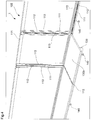
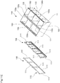
- Fig. 1 shows a section of a frame structure according to the invention 100, which is constructed on the wall of a room, with a subframe 110, of which two horizontal frame members 111 can be seen, and two vertical frame members 111, which divide the subframe 110 into smaller rectangles.
- the upper horizontal frame member 111 is formed as a simple bar, while the lower horizontal frame member 111 and the two vertical frame members 111 each have a groove profile 112 for inserting surface elements 130 (not shown).
- the vertical frame members 111 each have right and left of the groove profile 112 a rectangular profile 113 for insertion of rear wall elements 130c (not shown).
- the rear wall members 130c are held down by the rectangular profile 113 of the lower horizontal frame member 111 which extends above the groove profile 112 of the lower horizontal frame member 111.
- support elements 140 in the form of height-adjustable adjustable feet are mounted, with which the frame structure 100 can be aligned.
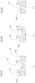
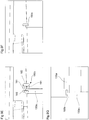
- FIGs. 2A-2C By way of example, three cross sections of frame elements 111 with different profiles are shown.
- Fig. 2A shows a cross-section of a frame member 111, as it, for example, the vertical frame members 111 in Fig. 1 exhibit. In the middle of the frame member 111 extends in the longitudinal direction of the frame member 111 has a groove 112. Left and right next to the groove profile 112 perpendicular profiles 113 which are oriented opposite to each other, so that at the edges of the frame member 111 bearing surfaces 113a formed, for example, for rear wall elements 130c become.
- Fig. 2B shows a cross section of a Frame member 111, for example, the lower horizontal frame member 111 in Fig. 1 having.
- the frame element 111 again has a groove profile 112. To the left of the groove profile 112 extends a right-angled profile 113, so that a bearing surface 113a is formed on the left-hand edge of the frame element 111. Depending on the installation position of the frame element 111 in the frame structure 100, the right-angled profile 113 can also be formed to the right of the groove profile 112 instead of to the left.
- the frame element 111 in FIG Fig. 2C has no groove profile 112, but only a rectangular profile 113 in the form of an L, wherein the edge of a surface element 130 comes to rest on the support surface 113a.
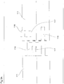
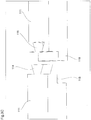
- Figs. 3A-3E show various ways that frame members 111 made of wood can be connected by wood joints to a rectangular sub-frame 110 or a divided frame structure 100.
- Figs. 3A-3C show compounds in which the two frame members 111 to be joined are oriented in the same direction (length joints).
- Figs. 3A and 3B show 90 degrees rotated views of the same connection.
- One of the frame members 111 has at one end a pin 114 which is pushed into a slot 115 at one end of the other frame member 111.
- a wood nail 116 is inserted into openings 117 in the region of the pin 114 and the slot 115.
- Fig. 3A-3E show various ways that frame members 111 made of wood can be connected by wood joints to a rectangular sub-frame 110 or a divided frame structure 100.
- Figs. 3A-3C show compounds in which the two frame members 111 to be joined are oriented in the same direction (length joints).
- Figs. 3A and 3B show
- FIG. 3C a length connection is shown in which the pin 114 is designed as a dovetail, which is inserted into a correspondingly shaped slot 115.
- both ends of the frame members 111 to be connected have a step portion 118, so that the respective stages come to lie one above the other.
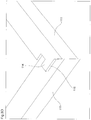
- Figs. 3D and 3E show compounds in which the two frame members 111 to be joined form a right angle (corner joints).
- the pin 114 of a frame member 111 is inserted into the slot 115 of the other frame member 111 so that the pin 114 faces the slot 115 in the longitudinal direction of the frame member 111.
- Fig. 3E shows a further embodiment of a corner joint with a pin 114 on a frame member 111 and a slot 115 on the other frame member, wherein the corner joint is formed as Schereckblatt.
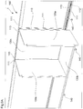
- Fig. 4 the frame structure 100 is off Fig. 1 shown, which is extended by a bottom element 130 b, which is inserted into the groove profile 112 of the lower horizontal frame member 111.
- the bottom element 130b is formed as a wooden plate, on the underside of a bar 135 is mounted parallel to the room wall.
- At the bar 135 are attached further support members 140, so that the furniture assembly 1 is supported not only on the frame structure 110, which is located at the back of the furniture assembly 1, but also on the bottom members 130 b near the front of the furniture assembly 1.
- the bottom element 130b has a groove profile 112, so that in the groove profile 112 of the bottom member 130b and in the groove profile 112 of the left vertical frame member 111, a wall member 130a (not shown) can be inserted, which is oriented perpendicular to the bottom element 130b.
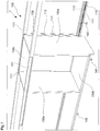
- Fig. 5 is the furniture assembly 1 off Fig. 4 completed by two wall elements 130a, which are inserted into the grooves 112 of the vertical frame members 111.
- Both wall elements 130a are formed as wood panels and each have at the upper front corner a recess 133 in the form of a rectangular cutout for receiving a crossbar 150 (not shown).
- the left wall element 130a is in the in Fig. 4 shown groove 112 of the bottom plate 130b inserted.
- the right wall element 130a extends to the bottom of the room and has at the lower end of another rectangular cutout 136 for receiving a shutter (not shown), which closes the open area between the room floor and floor element 130b forward.
- Fig. 6A is the furniture assembly 1 off Fig. 5 is supplemented by a rear wall element 130c oriented parallel to the room wall, which is held in position by the three rectangular profiles 113 of the two vertical frame elements 111 and the lower horizontal frame element 111.
- the rear wall member 130c may be additionally fixed to the frame members 111 by, for example, magnets or other fastening members (not shown).
- Fig. 6B shows a further embodiment of a furniture assembly 1 with three rear wall elements 130c.
- a great advantage of the furniture assembly 1 according to the invention becomes clear. If at the back 11 of the furniture assembly 1 areas of the rear wall should remain free, for example, so that sockets are accessible to the room wall or to provide a water connection, simply the respective rear wall element 130 c can be adapted or sawed out before it is inserted into the furniture assembly 1.
- the left rear panel 130c is in Fig. 6B in comparison to the others shorter two back wall elements 130c. This leaves an area on the rear side 11 of the furniture assembly 1 between the upper edge of the left rear wall element 130c and the upper horizontal frame element 111 free.
- the middle rear wall element 130c has two circular cutouts 137 in order, for example, to be able to access sockets.
- a usually already assembled body must be sawn again at the appropriate places, which is much more complex.
- Fig. 7 is the furniture assembly 1 off Fig. 6A formed around a trained as a wooden strip cross member 150 for stabilizing the furniture assembly 1, which is held in the recesses 133 of the wall elements 130a and parallel to the upper horizontal frame member 111 at the same height as this runs.
- the traverse 150 has a recess 151 which is formed as in the longitudinal direction of the traverse 150 extending cutout.
- Fig. 8A shows a portion of the cross member 150.
- material was removed at the top and at the front of the cross member, so that a handle bar is formed.
- the cross member 150 has on its underside and on its rear side a groove 112 into which the milled edges of the wall element 130a are inserted so that the cross member 150 does not slip in the recess 133.
- Fig. 8B shows a built-in furniture assembly 1 Traverse 150 with recess 151. By gripping into the recess 151 can be around the over the lower edge of the cross member 150 upstanding door member 170 herumgeriffen on the front of the furniture assembly 1 and the door member 170 are pivoted outward. Also visible are a worktop 190 as a cover of the furniture assembly 1 and a front element 131 on the front of the furniture assembly. 1
- fasteners 160a; 160b For fixing the connections between each two elements of the furniture assembly 1 (frame, surface or other elements) are fasteners 160a; 160b used.
- exemplary fasteners 160a for fixing a connection between two surface elements 130 are shown, with the two Surface elements 130 are arranged perpendicular to each other so that an edge of the first surface element 130 comes to rest on a surface of the second surface element 130.
- the fastening elements 160a are wedge-shaped elements which are fastened (eg screwed) onto the surface of the second surface element 130 ( Fig. 9A ).
- the edge of the first surface element 130 has a groove profile 112, so that the first surface element 130 can be pushed with the edge over the fastening element 160a ( Fig. 9B ).
- a plurality of fastening elements 160a are preferably screwed onto the surface of the second surface element 130 ( Fig. 9C ).
- Fig. 9D shows the wedge-shaped fasteners 160a in detail.
- a fastening element 160a has in each case a bore 163 at the two opposite end sections, so that the fastening element 160a can be fixed on the second surface element 130, for example with the aid of screws.
- FIG Figs. 9E-9G Other exemplary fasteners 160b are shown in FIG Figs. 9E-9G shown.
- a fastener 160b may be formed, for example, as a U-shaped clamp and two pins 161 which are connected via a bridge portion 162.
- the pins 161 are threaded and are inserted into a double bore 161, wherein both connected elements of the furniture assembly 1 each have a hole.
- the double bore 165 may be mounted in a cutout for the bridge member 162 so that the fastener 160 b does not protrude above the furniture assembly 1.
- the fastener 160 b fixes the connection of two elements of the furniture assembly 1 in vertical ( Fig. 9F ) or horizontal ( Fig. 9G ) Direction.
- FIG. 12 shows a drawn drawer 180 of a furniture assembly 1, illustrating how the front cover 180a of the drawer 180 is raised above the lower edge 150a of a crossbar 150 so that the drawer 180 can be easily and conveniently pulled up.
- Figs. 11A-E show various types of furniture bodies 10, of which a furniture assembly 1 may consist.
- a furniture body 10 is not limited to the types shown.
- Figs. 11A-D each show a type (line 10a in Fig. 11A , Tall cabinet 10b in Fig. 11B , Wall unit 10c in Fig. 11C and panel 10e in Fig. 11D ) from left to right in exploded view, in successive assembly steps and in assembled form.
- the frame structure 100 always always first turns off a rectangular outer frame 110 and further subdividing frame members 111 assembled.
- the rear wall elements 130c are subsequently inserted into the frame structure 100.
- the line 10a For the line 10a, the tall cabinet 10b and the upper cabinet 10c, the floor elements 130b, the side elements 132 on two opposite sides of the respective furniture body 10 and the vertical wall elements 130a (partitions) follow first.
- a traverse 150 can be used (line 10a), or cover elements 134 are placed as the upper surface boundary (tall cabinet 10b and upper cabinet 10c).
- the rear wall members 130c are inserted into the sub-frame 110.
- further wall elements 130a can be used as intermediate floors (upper cabinet 10b).
- Fig. 11E shows another type (island 11d) in various unfinished assembly steps.
- the subframe 110 is shown with four outer frame members 111 and two additional frame members 111 for subdivision.
- the subframe 110 can also be used as a receptacle on the island 10d at the rear.
- additional vertical frame elements 111 are added for subdivision.
- the vertical frame members 111 are located on both sides of the upper horizontal frame member 111, so that 100 compartments can be formed on both sides of the frame structure.
- two lower horizontal frame members 111 are provided so that bottom members 130b can be inserted on both sides of the island 10d.
- An island 11d can be arranged free-standing or with one or two of its side surfaces on a room wall or two room walls (corner) adjacent in space.
- a single row 10a may be arranged freestanding or with one or two of its side surfaces adjacent to a room wall or two room walls (corner) in space.
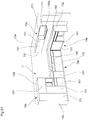
- Figs. 12-14 show by way of example various furniture assemblies 1 according to the invention, which are each designed as a kitchen.
- the furniture arrangement 1 in Fig. 12 extends over two walls of a room and thus runs over corner.
- the furniture assembly 1 has a tall cabinet 10b, two rows 10a and a top cabinet 10c.
- the furniture bodies 10 are, inter alia, shelf areas, kitchen appliances such as stove and oven, a sink and drawers 180 and countertops 190.
- the furniture assembly 1 in Fig. 13 is positioned on a single room wall and has a panel 10e, a line 10a and a top cabinet 10c.
- the basically vertically oriented frame structure 100 can also be extended in a horizontal direction, for example, to frame an illumination 200.
- the furniture arrangement 1 in Fig. 14 has a line 10a and a top cabinet 10c.
- additional panels or fittings may be mounted, which are fixed by means of standard holes in the side walls 132 or cover members 134.
- the process according to the invention for constructing the furniture assembly 1 will be discussed in greater detail.
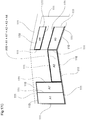
- the sub-frames 110 are basically designed so that each sub-frame 110 limits rectangular sub-frame surfaces A1-A4, wherein the sub-frame surfaces A1-A4 are selected so that a minimum number of sub-frame surfaces A1-A4 forms the back surface of the volume V (base assembly A10) ,
- the subframes 110 can be manufactured from a few, long frame elements 111.
- Fig. 17A corresponds to the base assembly A10, which must not be contiguous, the total area of the sub-frame surfaces A1 + A2 + A3 + A4.
- a first base area section A1 + A2 is arranged on the one wall of the room and a second base area section A3 + A4 is arranged on the other wall of the room and oriented perpendicular to the first base area section.
- the division of the base surface arrangement A10 into the minimum number of partial frame surfaces A1-A4 is not always clear.
- the base assembly A10 may be made Fig. 17A so too in the minimum number of four rectangular sub-frame surfaces A1-A4 are divided, as in Fig. 17B is shown.
- the decision for one or the other variant can be made taking into account additional criteria. For example, there may be the requirement to install a high refrigerator in the area of the subframe area A1. In this case, a breakdown according to Fig. 17A cheaper.
- a division according to Fig. 17A also offers itself because the distance of the upper outer contour 120 changes to the ground and there a vertical dividing line can be drawn, in the example of Fig. 17A the subframe surfaces A1 and A2 separates.
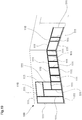
- a maximum length of the longitudinal or transverse strips (frame members 111) of the sub-frame 110 is specified for production-technical or spatial reasons. Then it may be necessary to have one or more of the sub-frame surfaces A1-A4 Fig. 17A or Fig. 17B into two smaller rectangular subframe surfaces (see the division of the left subframe surface into A1 and A1 'in Fig. 15C ).
- each subframe 110 is provided and assembled according to the planning with further frame elements 111 for further subdivision. So it is transported to the customer and mounted there in the given space ( Figs. 18-20 ). It is also possible to transport the frame elements 111 individually to the customer and only then assemble them into the subframes 110.
- the vertical frame members 111 are cut to the standard heights of the line and the cabinet and the grooves 112 are pre-routed.
- the horizontal frame elements 111 are individually cut to length according to the spatial planning. Recesses and connections of the frame members 111 are also milled on the basis of the spatial planning, so that the sub-frame 110 can already be assembled at the factory. During the planning steps a suitable software can be used. Even with different plans, the sub-frame 110 remain the same, only the milling and strut positions for the vertical frame members 111 change according to the plan. This enables flexible solutions for the customer.
- the frame structure 100 need not be built on a room wall, but may also be partially or completely free in space.
- the entire frame structure 100 can be aligned by means of adjustable feet (support elements 140) ( Fig. 21B ).
- the adjustable feet 140 are attached to the underside of the lower horizontal frame member 111 at the positions of the vertical frame members 111 and adjusted to the proper height.
- Other feet 140 are attached to the corresponding positions on the floor members 130b (not shown).
- it requires a much greater effort to align a conventional carcass kitchen, because each body has to be provided with four feet 140 ( Fig. 21A ).
- more feet 140 are necessary, which must all be set individually.
- the bottom elements 130b are inserted into the frame structure 100 and can additionally be screwed or glued in the groove 112 (FIG. Fig. 22 ).
- the arrangement is brought as a stable L in 90 °.
- Wall elements 130a are inserted as vertical partitions in the respective grooves 112 of the frame structure 100 and can be bolted or glued there. Side members 132 are added to the outer sides of the furniture assembly 1.
- the floor elements 130b are provided with the wall elements 130a with fastening elements 160a; 160b connected ( Fig. 23 ).
- the horizontally oriented wall elements 130a are inserted as intermediate floors or cover elements 134 in the respective grooves 112 of the frame structure and can be bolted or glued there and with fastening elements 160a; 160b are connected to the vertical wall and side elements 130a, 134 ( Fig. 24 ).
- the rear wall elements 130c are inserted into the rectangular profiles 113 of the frame structure 100 and can be held there for example with magnets or other fastening elements ( Fig. 25 ).
- the back walls 130c may be individually colored or coated.
- trusses 150 for stabilization and as handles be inserted.
- a cross member 150 can extend over several compartments of the furniture assembly 1, so for example be inserted into three or more Wandelementausfräsungen 133.
- the recess 151 for the function as a handle bar does not have to extend over the entire length of the traverse 150 ( Fig. 26 ).
- Fig. 27 shows an exemplary structure of a fully assembled furniture assembly 1 with a tall cabinet 10b, two rows 10a and a wall unit 10c.
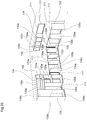
- Figs. 28A / B is again an exploded view of a corresponding conventional Korpi furniture arrangement ( Fig. 28A ) and a rawanordung invention 1 ( Fig. 28B ). While in the conventional arrangement 83 plates and diaphragms are used, this number reduces in the inventive arrangement 1 to 44 plates and diaphragms.
Landscapes
- Assembled Shelves (AREA)
Priority Applications (1)
| Application Number | Priority Date | Filing Date | Title |
|---|---|---|---|
| PL16205807T PL3183995T3 (pl) | 2015-12-22 | 2016-12-21 | Struktura ramowa do budowy układu mebli |
Applications Claiming Priority (1)
| Application Number | Priority Date | Filing Date | Title |
|---|---|---|---|
| DE102015226598.6A DE102015226598B4 (de) | 2015-12-22 | 2015-12-22 | Verfahren zum Aufbau einer Möbelanordnung und zugehörige Möbelanordnung |
Publications (2)
| Publication Number | Publication Date |
|---|---|
| EP3183995A1 true EP3183995A1 (fr) | 2017-06-28 |
| EP3183995B1 EP3183995B1 (fr) | 2021-11-17 |
Family
ID=57681359
Family Applications (1)
| Application Number | Title | Priority Date | Filing Date |
|---|---|---|---|
| EP16205807.7A Active EP3183995B1 (fr) | 2015-12-22 | 2016-12-21 | Structure de cadre pour realiser un arrangement de meubles |
Country Status (4)
| Country | Link |
|---|---|
| EP (1) | EP3183995B1 (fr) |
| DE (1) | DE102015226598B4 (fr) |
| ES (1) | ES2901149T3 (fr) |
| PL (1) | PL3183995T3 (fr) |
Cited By (1)
| Publication number | Priority date | Publication date | Assignee | Title |
|---|---|---|---|---|
| US12035805B2 (en) | 2021-02-08 | 2024-07-16 | Shiyuan Shen | Cabinets, cabinet assembly systems and methods of cabinet construction |
Families Citing this family (3)
| Publication number | Priority date | Publication date | Assignee | Title |
|---|---|---|---|---|
| KR20210110975A (ko) * | 2020-03-02 | 2021-09-10 | 엘지전자 주식회사 | 공간 배치형 냉장고 시스템 |
| DE102021203803B3 (de) | 2021-04-16 | 2022-09-08 | Blanco Gmbh + Co Kg | Rahmenelement zum Einbau in ein Arbeitsmöbel |
| DE102021133993A1 (de) | 2021-12-21 | 2023-06-22 | Paul Hettich Gmbh & Co. Kg | Möbel und Verfahren zur Positionierung eines Drehelements in einem Möbelkorpus eines Möbels |
Citations (3)
| Publication number | Priority date | Publication date | Assignee | Title |
|---|---|---|---|---|
| US4768845A (en) * | 1986-11-03 | 1988-09-06 | Yeh Kuo Huei | Combination-type desk/cabinet compartment structure |
| US20070283630A1 (en) * | 2006-06-11 | 2007-12-13 | Tayco Panelink Ltd. | Mounting system for workstations and the like |
| DE202009008825U1 (de) * | 2008-12-17 | 2009-10-15 | Unilin B.V.B.A. | Zusammengesetztes Element, mehrlagige Platte und paneelförmiges Element zum Formen solchen zusammengesetzten Elements |
Family Cites Families (6)
| Publication number | Priority date | Publication date | Assignee | Title |
|---|---|---|---|---|
| NL6603282A (fr) | 1965-03-30 | 1966-10-03 | ||
| DK9300191U3 (da) | 1993-04-05 | 1993-05-28 | Arkitektfirmaet Salling Morten | Inventarbyggesystem |
| DE29714821U1 (de) * | 1997-08-19 | 1997-10-16 | Gustav Wellmann GmbH & Co.KG, 32130 Enger | Küchenmöbelsystem in wangenbauweise, insbesondere zur un- und/oder bedingten Wandmontage |
| IT1311919B1 (it) | 1999-04-12 | 2002-03-20 | Schiffini Mobili Cucine Spa | Mobile ad elementi componibili, particolarmente studiato per cucine eper la casa. |
| DE20010930U1 (de) * | 2000-06-27 | 2000-10-19 | Fehre, Jürgen, 01665 Semmelsberg | Möbelkorpus |
| EP1366691B1 (fr) * | 2002-05-29 | 2009-01-21 | bulthaup GmbH & Co. KG | Système de meuble de cuisine |
-
2015
- 2015-12-22 DE DE102015226598.6A patent/DE102015226598B4/de active Active
-
2016
- 2016-12-21 EP EP16205807.7A patent/EP3183995B1/fr active Active
- 2016-12-21 PL PL16205807T patent/PL3183995T3/pl unknown
- 2016-12-21 ES ES16205807T patent/ES2901149T3/es active Active
Patent Citations (3)
| Publication number | Priority date | Publication date | Assignee | Title |
|---|---|---|---|---|
| US4768845A (en) * | 1986-11-03 | 1988-09-06 | Yeh Kuo Huei | Combination-type desk/cabinet compartment structure |
| US20070283630A1 (en) * | 2006-06-11 | 2007-12-13 | Tayco Panelink Ltd. | Mounting system for workstations and the like |
| DE202009008825U1 (de) * | 2008-12-17 | 2009-10-15 | Unilin B.V.B.A. | Zusammengesetztes Element, mehrlagige Platte und paneelförmiges Element zum Formen solchen zusammengesetzten Elements |
Cited By (1)
| Publication number | Priority date | Publication date | Assignee | Title |
|---|---|---|---|---|
| US12035805B2 (en) | 2021-02-08 | 2024-07-16 | Shiyuan Shen | Cabinets, cabinet assembly systems and methods of cabinet construction |
Also Published As
| Publication number | Publication date |
|---|---|
| EP3183995B1 (fr) | 2021-11-17 |
| DE102015226598B4 (de) | 2017-08-31 |
| PL3183995T3 (pl) | 2022-04-04 |
| DE102015226598A1 (de) | 2017-06-22 |
| ES2901149T3 (es) | 2022-03-21 |
Similar Documents
| Publication | Publication Date | Title |
|---|---|---|
| DE102010004605B4 (de) | Schubkasten | |
| EP2523577B1 (fr) | Tiroir, démontable et empilable | |
| EP3183995B1 (fr) | Structure de cadre pour realiser un arrangement de meubles | |
| EP2904942A2 (fr) | Étagère et/ou vitrine | |
| DE1778336C3 (de) | Möbelsystem für den Zusammenbau von Kastenmöbeln | |
| DE102021109616B4 (de) | Variables Möbelelement und modulares Möbelsystem aus mehreren Möbelelementen | |
| DE202015100228U1 (de) | Einrichtung zur Schallabsorption | |
| EP1264564B1 (fr) | Corps de meuble | |
| DE2701969A1 (de) | Regal | |
| DE10127311B4 (de) | Möbelkorpus | |
| DE102019200715A1 (de) | Profil zum Aufbau von Betriebseinrichtungen und Betriebseinrichtung | |
| DE2264143C2 (de) | Bausystem | |
| DE10235918B4 (de) | Montagesystem für Möbel und Verfahren zur Montage von Möbeln | |
| DE202018103987U1 (de) | Möbelsystem zum Bau von unterschiedlichen Möbelarrangements | |
| WO2003090582A1 (fr) | Element de structure sous forme de barre servant a l'assemblage d'un bati | |
| DE10328405B4 (de) | Schaltschrank | |
| DE202022100328U1 (de) | Modulares Regalsystem | |
| DE102016103149B4 (de) | Container-Aufbewahrungssystem | |
| DE102014104342B4 (de) | Verbindungssystem, insbesondere für Möbel | |
| DE2446797A1 (de) | Profilstab fuer ein regal und daraus hergestelltes regal | |
| DE20214202U1 (de) | Modulares, selbsttragendes Wandpaneel | |
| DE3737112A1 (de) | System von zusammensetzbaren elementegruppen aus grundelementen | |
| EP0784160A1 (fr) | Présentation de vente | |
| DE102019116634A1 (de) | Modulares Präsentationsset | |
| WO2007045115A1 (fr) | Etagere |
Legal Events
| Date | Code | Title | Description |
|---|---|---|---|
| PUAI | Public reference made under article 153(3) epc to a published international application that has entered the european phase |
Free format text: ORIGINAL CODE: 0009012 |
|
| STAA | Information on the status of an ep patent application or granted ep patent |
Free format text: STATUS: THE APPLICATION HAS BEEN PUBLISHED |
|
| AK | Designated contracting states |
Kind code of ref document: A1 Designated state(s): AL AT BE BG CH CY CZ DE DK EE ES FI FR GB GR HR HU IE IS IT LI LT LU LV MC MK MT NL NO PL PT RO RS SE SI SK SM TR |
|
| AX | Request for extension of the european patent |
Extension state: BA ME |
|
| STAA | Information on the status of an ep patent application or granted ep patent |
Free format text: STATUS: REQUEST FOR EXAMINATION WAS MADE |
|
| 17P | Request for examination filed |
Effective date: 20180102 |
|
| RBV | Designated contracting states (corrected) |
Designated state(s): AL AT BE BG CH CY CZ DE DK EE ES FI FR GB GR HR HU IE IS IT LI LT LU LV MC MK MT NL NO PL PT RO RS SE SI SK SM TR |
|
| STAA | Information on the status of an ep patent application or granted ep patent |
Free format text: STATUS: EXAMINATION IS IN PROGRESS |
|
| 17Q | First examination report despatched |
Effective date: 20181109 |
|
| GRAP | Despatch of communication of intention to grant a patent |
Free format text: ORIGINAL CODE: EPIDOSNIGR1 |
|
| STAA | Information on the status of an ep patent application or granted ep patent |
Free format text: STATUS: GRANT OF PATENT IS INTENDED |
|
| INTG | Intention to grant announced |
Effective date: 20210616 |
|
| GRAS | Grant fee paid |
Free format text: ORIGINAL CODE: EPIDOSNIGR3 |
|
| GRAA | (expected) grant |
Free format text: ORIGINAL CODE: 0009210 |
|
| STAA | Information on the status of an ep patent application or granted ep patent |
Free format text: STATUS: THE PATENT HAS BEEN GRANTED |
|
| AK | Designated contracting states |
Kind code of ref document: B1 Designated state(s): AL AT BE BG CH CY CZ DE DK EE ES FI FR GB GR HR HU IE IS IT LI LT LU LV MC MK MT NL NO PL PT RO RS SE SI SK SM TR |
|
| RAP3 | Party data changed (applicant data changed or rights of an application transferred) |
Owner name: PETRI, TOBIAS Owner name: PETZOLD, SVEN |
|
| REG | Reference to a national code |
Ref country code: GB Ref legal event code: FG4D Free format text: NOT ENGLISH |
|
| RIN1 | Information on inventor provided before grant (corrected) |
Inventor name: KELLERMANN, GERHARD Inventor name: RELVAO, ANA Inventor name: HEINZELMANN, JAN Inventor name: PETRI, TOBIAS Inventor name: PETZOLD, SVEN |
|
| REG | Reference to a national code |
Ref country code: IE Ref legal event code: FG4D Free format text: LANGUAGE OF EP DOCUMENT: GERMAN |
|
| REG | Reference to a national code |
Ref country code: DE Ref legal event code: R096 Ref document number: 502016014156 Country of ref document: DE |
|
| REG | Reference to a national code |
Ref country code: AT Ref legal event code: REF Ref document number: 1447342 Country of ref document: AT Kind code of ref document: T Effective date: 20211215 |
|
| REG | Reference to a national code |
Ref country code: LT Ref legal event code: MG9D |
|
| REG | Reference to a national code |
Ref country code: ES Ref legal event code: FG2A Ref document number: 2901149 Country of ref document: ES Kind code of ref document: T3 Effective date: 20220321 |
|
| REG | Reference to a national code |
Ref country code: NL Ref legal event code: MP Effective date: 20211117 |
|
| PG25 | Lapsed in a contracting state [announced via postgrant information from national office to epo] |
Ref country code: RS Free format text: LAPSE BECAUSE OF FAILURE TO SUBMIT A TRANSLATION OF THE DESCRIPTION OR TO PAY THE FEE WITHIN THE PRESCRIBED TIME-LIMIT Effective date: 20211117 Ref country code: LT Free format text: LAPSE BECAUSE OF FAILURE TO SUBMIT A TRANSLATION OF THE DESCRIPTION OR TO PAY THE FEE WITHIN THE PRESCRIBED TIME-LIMIT Effective date: 20211117 Ref country code: FI Free format text: LAPSE BECAUSE OF FAILURE TO SUBMIT A TRANSLATION OF THE DESCRIPTION OR TO PAY THE FEE WITHIN THE PRESCRIBED TIME-LIMIT Effective date: 20211117 Ref country code: BG Free format text: LAPSE BECAUSE OF FAILURE TO SUBMIT A TRANSLATION OF THE DESCRIPTION OR TO PAY THE FEE WITHIN THE PRESCRIBED TIME-LIMIT Effective date: 20220217 |
|
| REG | Reference to a national code |
Ref country code: SK Ref legal event code: T3 Ref document number: E 39138 Country of ref document: SK |
|
| PG25 | Lapsed in a contracting state [announced via postgrant information from national office to epo] |
Ref country code: IS Free format text: LAPSE BECAUSE OF FAILURE TO SUBMIT A TRANSLATION OF THE DESCRIPTION OR TO PAY THE FEE WITHIN THE PRESCRIBED TIME-LIMIT Effective date: 20220317 Ref country code: SE Free format text: LAPSE BECAUSE OF FAILURE TO SUBMIT A TRANSLATION OF THE DESCRIPTION OR TO PAY THE FEE WITHIN THE PRESCRIBED TIME-LIMIT Effective date: 20211117 Ref country code: PT Free format text: LAPSE BECAUSE OF FAILURE TO SUBMIT A TRANSLATION OF THE DESCRIPTION OR TO PAY THE FEE WITHIN THE PRESCRIBED TIME-LIMIT Effective date: 20220317 Ref country code: NO Free format text: LAPSE BECAUSE OF FAILURE TO SUBMIT A TRANSLATION OF THE DESCRIPTION OR TO PAY THE FEE WITHIN THE PRESCRIBED TIME-LIMIT Effective date: 20220217 Ref country code: NL Free format text: LAPSE BECAUSE OF FAILURE TO SUBMIT A TRANSLATION OF THE DESCRIPTION OR TO PAY THE FEE WITHIN THE PRESCRIBED TIME-LIMIT Effective date: 20211117 Ref country code: LV Free format text: LAPSE BECAUSE OF FAILURE TO SUBMIT A TRANSLATION OF THE DESCRIPTION OR TO PAY THE FEE WITHIN THE PRESCRIBED TIME-LIMIT Effective date: 20211117 Ref country code: HR Free format text: LAPSE BECAUSE OF FAILURE TO SUBMIT A TRANSLATION OF THE DESCRIPTION OR TO PAY THE FEE WITHIN THE PRESCRIBED TIME-LIMIT Effective date: 20211117 Ref country code: GR Free format text: LAPSE BECAUSE OF FAILURE TO SUBMIT A TRANSLATION OF THE DESCRIPTION OR TO PAY THE FEE WITHIN THE PRESCRIBED TIME-LIMIT Effective date: 20220218 |
|
| PG25 | Lapsed in a contracting state [announced via postgrant information from national office to epo] |
Ref country code: SM Free format text: LAPSE BECAUSE OF FAILURE TO SUBMIT A TRANSLATION OF THE DESCRIPTION OR TO PAY THE FEE WITHIN THE PRESCRIBED TIME-LIMIT Effective date: 20211117 Ref country code: RO Free format text: LAPSE BECAUSE OF FAILURE TO SUBMIT A TRANSLATION OF THE DESCRIPTION OR TO PAY THE FEE WITHIN THE PRESCRIBED TIME-LIMIT Effective date: 20211117 Ref country code: EE Free format text: LAPSE BECAUSE OF FAILURE TO SUBMIT A TRANSLATION OF THE DESCRIPTION OR TO PAY THE FEE WITHIN THE PRESCRIBED TIME-LIMIT Effective date: 20211117 Ref country code: DK Free format text: LAPSE BECAUSE OF FAILURE TO SUBMIT A TRANSLATION OF THE DESCRIPTION OR TO PAY THE FEE WITHIN THE PRESCRIBED TIME-LIMIT Effective date: 20211117 |
|
| REG | Reference to a national code |
Ref country code: DE Ref legal event code: R097 Ref document number: 502016014156 Country of ref document: DE |
|
| PG25 | Lapsed in a contracting state [announced via postgrant information from national office to epo] |
Ref country code: MC Free format text: LAPSE BECAUSE OF FAILURE TO SUBMIT A TRANSLATION OF THE DESCRIPTION OR TO PAY THE FEE WITHIN THE PRESCRIBED TIME-LIMIT Effective date: 20211117 |
|
| PLBE | No opposition filed within time limit |
Free format text: ORIGINAL CODE: 0009261 |
|
| STAA | Information on the status of an ep patent application or granted ep patent |
Free format text: STATUS: NO OPPOSITION FILED WITHIN TIME LIMIT |
|
| REG | Reference to a national code |
Ref country code: BE Ref legal event code: MM Effective date: 20211231 |
|
| 26N | No opposition filed |
Effective date: 20220818 |
|
| PG25 | Lapsed in a contracting state [announced via postgrant information from national office to epo] |
Ref country code: LU Free format text: LAPSE BECAUSE OF NON-PAYMENT OF DUE FEES Effective date: 20211221 Ref country code: IE Free format text: LAPSE BECAUSE OF NON-PAYMENT OF DUE FEES Effective date: 20211221 Ref country code: AL Free format text: LAPSE BECAUSE OF FAILURE TO SUBMIT A TRANSLATION OF THE DESCRIPTION OR TO PAY THE FEE WITHIN THE PRESCRIBED TIME-LIMIT Effective date: 20211117 |
|
| PG25 | Lapsed in a contracting state [announced via postgrant information from national office to epo] |
Ref country code: SI Free format text: LAPSE BECAUSE OF FAILURE TO SUBMIT A TRANSLATION OF THE DESCRIPTION OR TO PAY THE FEE WITHIN THE PRESCRIBED TIME-LIMIT Effective date: 20211117 Ref country code: BE Free format text: LAPSE BECAUSE OF NON-PAYMENT OF DUE FEES Effective date: 20211231 |
|
| PG25 | Lapsed in a contracting state [announced via postgrant information from national office to epo] |
Ref country code: HU Free format text: LAPSE BECAUSE OF FAILURE TO SUBMIT A TRANSLATION OF THE DESCRIPTION OR TO PAY THE FEE WITHIN THE PRESCRIBED TIME-LIMIT; INVALID AB INITIO Effective date: 20161221 |
|
| PG25 | Lapsed in a contracting state [announced via postgrant information from national office to epo] |
Ref country code: CY Free format text: LAPSE BECAUSE OF FAILURE TO SUBMIT A TRANSLATION OF THE DESCRIPTION OR TO PAY THE FEE WITHIN THE PRESCRIBED TIME-LIMIT Effective date: 20211117 |
|
| PG25 | Lapsed in a contracting state [announced via postgrant information from national office to epo] |
Ref country code: MK Free format text: LAPSE BECAUSE OF FAILURE TO SUBMIT A TRANSLATION OF THE DESCRIPTION OR TO PAY THE FEE WITHIN THE PRESCRIBED TIME-LIMIT Effective date: 20211117 |
|
| PG25 | Lapsed in a contracting state [announced via postgrant information from national office to epo] |
Ref country code: MT Free format text: LAPSE BECAUSE OF FAILURE TO SUBMIT A TRANSLATION OF THE DESCRIPTION OR TO PAY THE FEE WITHIN THE PRESCRIBED TIME-LIMIT Effective date: 20211117 |
|
| PG25 | Lapsed in a contracting state [announced via postgrant information from national office to epo] |
Ref country code: TR Free format text: LAPSE BECAUSE OF FAILURE TO SUBMIT A TRANSLATION OF THE DESCRIPTION OR TO PAY THE FEE WITHIN THE PRESCRIBED TIME-LIMIT Effective date: 20211117 |
|
| REG | Reference to a national code |
Ref country code: CH Ref legal event code: U11 Free format text: ST27 STATUS EVENT CODE: U-0-0-U10-U11 (AS PROVIDED BY THE NATIONAL OFFICE) Effective date: 20260101 |
|
| PGFP | Annual fee paid to national office [announced via postgrant information from national office to epo] |
Ref country code: GB Payment date: 20251218 Year of fee payment: 10 |
|
| PGFP | Annual fee paid to national office [announced via postgrant information from national office to epo] |
Ref country code: AT Payment date: 20251215 Year of fee payment: 10 |
|
| PGFP | Annual fee paid to national office [announced via postgrant information from national office to epo] |
Ref country code: FR Payment date: 20251218 Year of fee payment: 10 |
|
| PGFP | Annual fee paid to national office [announced via postgrant information from national office to epo] |
Ref country code: CZ Payment date: 20251209 Year of fee payment: 10 |
|
| PGFP | Annual fee paid to national office [announced via postgrant information from national office to epo] |
Ref country code: PL Payment date: 20251205 Year of fee payment: 10 |
|
| PGFP | Annual fee paid to national office [announced via postgrant information from national office to epo] |
Ref country code: SK Payment date: 20251217 Year of fee payment: 10 |
|
| PGFP | Annual fee paid to national office [announced via postgrant information from national office to epo] |
Ref country code: ES Payment date: 20260119 Year of fee payment: 10 |
|
| PGFP | Annual fee paid to national office [announced via postgrant information from national office to epo] |
Ref country code: DE Payment date: 20251231 Year of fee payment: 10 |
|
| PGFP | Annual fee paid to national office [announced via postgrant information from national office to epo] |
Ref country code: IT Payment date: 20251231 Year of fee payment: 10 |
|
| PGFP | Annual fee paid to national office [announced via postgrant information from national office to epo] |
Ref country code: CH Payment date: 20260101 Year of fee payment: 10 |