EP3184239B1 - Bearbeitungssystem - Google Patents
Bearbeitungssystem Download PDFInfo
- Publication number
- EP3184239B1 EP3184239B1 EP14899988.1A EP14899988A EP3184239B1 EP 3184239 B1 EP3184239 B1 EP 3184239B1 EP 14899988 A EP14899988 A EP 14899988A EP 3184239 B1 EP3184239 B1 EP 3184239B1
- Authority
- EP
- European Patent Office
- Prior art keywords
- tool
- module
- work
- base
- main shaft
- Prior art date
- Legal status (The legal status is an assumption and is not a legal conclusion. Google has not performed a legal analysis and makes no representation as to the accuracy of the status listed.)
- Active
Links
Images





Classifications
-
- B—PERFORMING OPERATIONS; TRANSPORTING
- B23—MACHINE TOOLS; METAL-WORKING NOT OTHERWISE PROVIDED FOR
- B23Q—DETAILS, COMPONENTS, OR ACCESSORIES FOR MACHINE TOOLS, e.g. ARRANGEMENTS FOR COPYING OR CONTROLLING; MACHINE TOOLS IN GENERAL CHARACTERISED BY THE CONSTRUCTION OF PARTICULAR DETAILS OR COMPONENTS; COMBINATIONS OR ASSOCIATIONS OF METAL-WORKING MACHINES, NOT DIRECTED TO A PARTICULAR RESULT
- B23Q41/00—Combinations or associations of metal-working machines not directed to a particular result according to classes B21, B23, or B24
- B23Q41/04—Features relating to relative arrangements of machines
-
- B—PERFORMING OPERATIONS; TRANSPORTING
- B23—MACHINE TOOLS; METAL-WORKING NOT OTHERWISE PROVIDED FOR
- B23C—MILLING
- B23C1/00—Milling machines not designed for particular work or special operations
- B23C1/002—Gantry-type milling machines
-
- B—PERFORMING OPERATIONS; TRANSPORTING
- B23—MACHINE TOOLS; METAL-WORKING NOT OTHERWISE PROVIDED FOR
- B23C—MILLING
- B23C1/00—Milling machines not designed for particular work or special operations
- B23C1/14—Milling machines not designed for particular work or special operations with rotary work-carrying table
-
- B—PERFORMING OPERATIONS; TRANSPORTING
- B23—MACHINE TOOLS; METAL-WORKING NOT OTHERWISE PROVIDED FOR
- B23P—METAL-WORKING NOT OTHERWISE PROVIDED FOR; COMBINED OPERATIONS; UNIVERSAL MACHINE TOOLS
- B23P23/00—Machines or arrangements of machines for performing specified combinations of different metal-working operations not covered by a single other subclass
-
- B—PERFORMING OPERATIONS; TRANSPORTING
- B23—MACHINE TOOLS; METAL-WORKING NOT OTHERWISE PROVIDED FOR
- B23P—METAL-WORKING NOT OTHERWISE PROVIDED FOR; COMBINED OPERATIONS; UNIVERSAL MACHINE TOOLS
- B23P23/00—Machines or arrangements of machines for performing specified combinations of different metal-working operations not covered by a single other subclass
- B23P23/02—Machine tools for performing different machining operations
-
- B—PERFORMING OPERATIONS; TRANSPORTING
- B23—MACHINE TOOLS; METAL-WORKING NOT OTHERWISE PROVIDED FOR
- B23Q—DETAILS, COMPONENTS, OR ACCESSORIES FOR MACHINE TOOLS, e.g. ARRANGEMENTS FOR COPYING OR CONTROLLING; MACHINE TOOLS IN GENERAL CHARACTERISED BY THE CONSTRUCTION OF PARTICULAR DETAILS OR COMPONENTS; COMBINATIONS OR ASSOCIATIONS OF METAL-WORKING MACHINES, NOT DIRECTED TO A PARTICULAR RESULT
- B23Q1/00—Members which are comprised in the general build-up of a form of machine, particularly relatively large fixed members
-
- B—PERFORMING OPERATIONS; TRANSPORTING
- B23—MACHINE TOOLS; METAL-WORKING NOT OTHERWISE PROVIDED FOR
- B23Q—DETAILS, COMPONENTS, OR ACCESSORIES FOR MACHINE TOOLS, e.g. ARRANGEMENTS FOR COPYING OR CONTROLLING; MACHINE TOOLS IN GENERAL CHARACTERISED BY THE CONSTRUCTION OF PARTICULAR DETAILS OR COMPONENTS; COMBINATIONS OR ASSOCIATIONS OF METAL-WORKING MACHINES, NOT DIRECTED TO A PARTICULAR RESULT
- B23Q1/00—Members which are comprised in the general build-up of a form of machine, particularly relatively large fixed members
- B23Q1/25—Movable or adjustable work or tool supports
- B23Q1/44—Movable or adjustable work or tool supports using particular mechanisms
- B23Q1/56—Movable or adjustable work or tool supports using particular mechanisms with sliding pairs only, the sliding pairs being the first two elements of the mechanism
- B23Q1/58—Movable or adjustable work or tool supports using particular mechanisms with sliding pairs only, the sliding pairs being the first two elements of the mechanism a single sliding pair
-
- B—PERFORMING OPERATIONS; TRANSPORTING
- B23—MACHINE TOOLS; METAL-WORKING NOT OTHERWISE PROVIDED FOR
- B23Q—DETAILS, COMPONENTS, OR ACCESSORIES FOR MACHINE TOOLS, e.g. ARRANGEMENTS FOR COPYING OR CONTROLLING; MACHINE TOOLS IN GENERAL CHARACTERISED BY THE CONSTRUCTION OF PARTICULAR DETAILS OR COMPONENTS; COMBINATIONS OR ASSOCIATIONS OF METAL-WORKING MACHINES, NOT DIRECTED TO A PARTICULAR RESULT
- B23Q1/00—Members which are comprised in the general build-up of a form of machine, particularly relatively large fixed members
- B23Q1/25—Movable or adjustable work or tool supports
- B23Q1/44—Movable or adjustable work or tool supports using particular mechanisms
- B23Q1/56—Movable or adjustable work or tool supports using particular mechanisms with sliding pairs only, the sliding pairs being the first two elements of the mechanism
- B23Q1/60—Movable or adjustable work or tool supports using particular mechanisms with sliding pairs only, the sliding pairs being the first two elements of the mechanism two sliding pairs only, the sliding pairs being the first two elements of the mechanism
- B23Q1/62—Movable or adjustable work or tool supports using particular mechanisms with sliding pairs only, the sliding pairs being the first two elements of the mechanism two sliding pairs only, the sliding pairs being the first two elements of the mechanism with perpendicular axes, e.g. cross-slides
- B23Q1/621—Movable or adjustable work or tool supports using particular mechanisms with sliding pairs only, the sliding pairs being the first two elements of the mechanism two sliding pairs only, the sliding pairs being the first two elements of the mechanism with perpendicular axes, e.g. cross-slides a single sliding pair followed perpendicularly by a single sliding pair
- B23Q1/626—Movable or adjustable work or tool supports using particular mechanisms with sliding pairs only, the sliding pairs being the first two elements of the mechanism two sliding pairs only, the sliding pairs being the first two elements of the mechanism with perpendicular axes, e.g. cross-slides a single sliding pair followed perpendicularly by a single sliding pair followed perpendicularly by a single sliding pair
-
- B—PERFORMING OPERATIONS; TRANSPORTING
- B23—MACHINE TOOLS; METAL-WORKING NOT OTHERWISE PROVIDED FOR
- B23Q—DETAILS, COMPONENTS, OR ACCESSORIES FOR MACHINE TOOLS, e.g. ARRANGEMENTS FOR COPYING OR CONTROLLING; MACHINE TOOLS IN GENERAL CHARACTERISED BY THE CONSTRUCTION OF PARTICULAR DETAILS OR COMPONENTS; COMBINATIONS OR ASSOCIATIONS OF METAL-WORKING MACHINES, NOT DIRECTED TO A PARTICULAR RESULT
- B23Q11/00—Accessories fitted to machine tools for keeping tools or parts of the machine in good working condition or for cooling work; Safety devices specially combined with or arranged in, or specially adapted for use in connection with, machine tools
- B23Q11/0042—Devices for removing chips
- B23Q11/0057—Devices for removing chips outside the working area
-
- B—PERFORMING OPERATIONS; TRANSPORTING
- B23—MACHINE TOOLS; METAL-WORKING NOT OTHERWISE PROVIDED FOR
- B23Q—DETAILS, COMPONENTS, OR ACCESSORIES FOR MACHINE TOOLS, e.g. ARRANGEMENTS FOR COPYING OR CONTROLLING; MACHINE TOOLS IN GENERAL CHARACTERISED BY THE CONSTRUCTION OF PARTICULAR DETAILS OR COMPONENTS; COMBINATIONS OR ASSOCIATIONS OF METAL-WORKING MACHINES, NOT DIRECTED TO A PARTICULAR RESULT
- B23Q11/00—Accessories fitted to machine tools for keeping tools or parts of the machine in good working condition or for cooling work; Safety devices specially combined with or arranged in, or specially adapted for use in connection with, machine tools
- B23Q11/0042—Devices for removing chips
- B23Q11/0067—Devices for removing chips chip containers located under a machine or under a chip conveyor
-
- B—PERFORMING OPERATIONS; TRANSPORTING
- B23—MACHINE TOOLS; METAL-WORKING NOT OTHERWISE PROVIDED FOR
- B23Q—DETAILS, COMPONENTS, OR ACCESSORIES FOR MACHINE TOOLS, e.g. ARRANGEMENTS FOR COPYING OR CONTROLLING; MACHINE TOOLS IN GENERAL CHARACTERISED BY THE CONSTRUCTION OF PARTICULAR DETAILS OR COMPONENTS; COMBINATIONS OR ASSOCIATIONS OF METAL-WORKING MACHINES, NOT DIRECTED TO A PARTICULAR RESULT
- B23Q3/00—Devices holding, supporting, or positioning work or tools, of a kind normally removable from the machine
- B23Q3/155—Arrangements for automatic insertion or removal of tools, e.g. combined with manual handling
- B23Q3/157—Arrangements for automatic insertion or removal of tools, e.g. combined with manual handling of rotary tools
- B23Q3/15706—Arrangements for automatic insertion or removal of tools, e.g. combined with manual handling of rotary tools a single tool being inserted in a spindle directly from a storage device, i.e. without using transfer devices
-
- B—PERFORMING OPERATIONS; TRANSPORTING
- B23—MACHINE TOOLS; METAL-WORKING NOT OTHERWISE PROVIDED FOR
- B23Q—DETAILS, COMPONENTS, OR ACCESSORIES FOR MACHINE TOOLS, e.g. ARRANGEMENTS FOR COPYING OR CONTROLLING; MACHINE TOOLS IN GENERAL CHARACTERISED BY THE CONSTRUCTION OF PARTICULAR DETAILS OR COMPONENTS; COMBINATIONS OR ASSOCIATIONS OF METAL-WORKING MACHINES, NOT DIRECTED TO A PARTICULAR RESULT
- B23Q37/00—Metal-working machines, or constructional combinations thereof, built-up from units designed so that at least some of the units can form parts of different machines or combinations; Units therefor in so far as the feature of interchangeability is important
-
- B—PERFORMING OPERATIONS; TRANSPORTING
- B23—MACHINE TOOLS; METAL-WORKING NOT OTHERWISE PROVIDED FOR
- B23Q—DETAILS, COMPONENTS, OR ACCESSORIES FOR MACHINE TOOLS, e.g. ARRANGEMENTS FOR COPYING OR CONTROLLING; MACHINE TOOLS IN GENERAL CHARACTERISED BY THE CONSTRUCTION OF PARTICULAR DETAILS OR COMPONENTS; COMBINATIONS OR ASSOCIATIONS OF METAL-WORKING MACHINES, NOT DIRECTED TO A PARTICULAR RESULT
- B23Q37/00—Metal-working machines, or constructional combinations thereof, built-up from units designed so that at least some of the units can form parts of different machines or combinations; Units therefor in so far as the feature of interchangeability is important
- B23Q37/007—Modular machining stations designed to be linked to each other
-
- B—PERFORMING OPERATIONS; TRANSPORTING
- B23—MACHINE TOOLS; METAL-WORKING NOT OTHERWISE PROVIDED FOR
- B23Q—DETAILS, COMPONENTS, OR ACCESSORIES FOR MACHINE TOOLS, e.g. ARRANGEMENTS FOR COPYING OR CONTROLLING; MACHINE TOOLS IN GENERAL CHARACTERISED BY THE CONSTRUCTION OF PARTICULAR DETAILS OR COMPONENTS; COMBINATIONS OR ASSOCIATIONS OF METAL-WORKING MACHINES, NOT DIRECTED TO A PARTICULAR RESULT
- B23Q41/00—Combinations or associations of metal-working machines not directed to a particular result according to classes B21, B23, or B24
-
- B—PERFORMING OPERATIONS; TRANSPORTING
- B23—MACHINE TOOLS; METAL-WORKING NOT OTHERWISE PROVIDED FOR
- B23C—MILLING
- B23C1/00—Milling machines not designed for particular work or special operations
- B23C1/06—Milling machines not designed for particular work or special operations with one vertical working-spindle
-
- B—PERFORMING OPERATIONS; TRANSPORTING
- B23—MACHINE TOOLS; METAL-WORKING NOT OTHERWISE PROVIDED FOR
- B23Q—DETAILS, COMPONENTS, OR ACCESSORIES FOR MACHINE TOOLS, e.g. ARRANGEMENTS FOR COPYING OR CONTROLLING; MACHINE TOOLS IN GENERAL CHARACTERISED BY THE CONSTRUCTION OF PARTICULAR DETAILS OR COMPONENTS; COMBINATIONS OR ASSOCIATIONS OF METAL-WORKING MACHINES, NOT DIRECTED TO A PARTICULAR RESULT
- B23Q1/00—Members which are comprised in the general build-up of a form of machine, particularly relatively large fixed members
- B23Q1/25—Movable or adjustable work or tool supports
- B23Q1/44—Movable or adjustable work or tool supports using particular mechanisms
- B23Q1/50—Movable or adjustable work or tool supports using particular mechanisms with rotating pairs only, the rotating pairs being the first two elements of the mechanism
- B23Q1/52—Movable or adjustable work or tool supports using particular mechanisms with rotating pairs only, the rotating pairs being the first two elements of the mechanism a single rotating pair
- B23Q1/525—Movable or adjustable work or tool supports using particular mechanisms with rotating pairs only, the rotating pairs being the first two elements of the mechanism a single rotating pair which is parallel to the working surface
-
- B—PERFORMING OPERATIONS; TRANSPORTING
- B23—MACHINE TOOLS; METAL-WORKING NOT OTHERWISE PROVIDED FOR
- B23Q—DETAILS, COMPONENTS, OR ACCESSORIES FOR MACHINE TOOLS, e.g. ARRANGEMENTS FOR COPYING OR CONTROLLING; MACHINE TOOLS IN GENERAL CHARACTERISED BY THE CONSTRUCTION OF PARTICULAR DETAILS OR COMPONENTS; COMBINATIONS OR ASSOCIATIONS OF METAL-WORKING MACHINES, NOT DIRECTED TO A PARTICULAR RESULT
- B23Q11/00—Accessories fitted to machine tools for keeping tools or parts of the machine in good working condition or for cooling work; Safety devices specially combined with or arranged in, or specially adapted for use in connection with, machine tools
- B23Q11/08—Protective coverings for parts of machine tools; Splash guards
-
- B—PERFORMING OPERATIONS; TRANSPORTING
- B23—MACHINE TOOLS; METAL-WORKING NOT OTHERWISE PROVIDED FOR
- B23Q—DETAILS, COMPONENTS, OR ACCESSORIES FOR MACHINE TOOLS, e.g. ARRANGEMENTS FOR COPYING OR CONTROLLING; MACHINE TOOLS IN GENERAL CHARACTERISED BY THE CONSTRUCTION OF PARTICULAR DETAILS OR COMPONENTS; COMBINATIONS OR ASSOCIATIONS OF METAL-WORKING MACHINES, NOT DIRECTED TO A PARTICULAR RESULT
- B23Q3/00—Devices holding, supporting, or positioning work or tools, of a kind normally removable from the machine
- B23Q3/155—Arrangements for automatic insertion or removal of tools, e.g. combined with manual handling
- B23Q3/1552—Arrangements for automatic insertion or removal of tools, e.g. combined with manual handling parts of devices for automatically inserting or removing tools
- B23Q3/15526—Storage devices; Drive mechanisms therefor
- B23Q2003/15537—Linearly moving storage devices
-
- B—PERFORMING OPERATIONS; TRANSPORTING
- B23—MACHINE TOOLS; METAL-WORKING NOT OTHERWISE PROVIDED FOR
- B23Q—DETAILS, COMPONENTS, OR ACCESSORIES FOR MACHINE TOOLS, e.g. ARRANGEMENTS FOR COPYING OR CONTROLLING; MACHINE TOOLS IN GENERAL CHARACTERISED BY THE CONSTRUCTION OF PARTICULAR DETAILS OR COMPONENTS; COMBINATIONS OR ASSOCIATIONS OF METAL-WORKING MACHINES, NOT DIRECTED TO A PARTICULAR RESULT
- B23Q3/00—Devices holding, supporting, or positioning work or tools, of a kind normally removable from the machine
- B23Q3/155—Arrangements for automatic insertion or removal of tools, e.g. combined with manual handling
- B23Q3/1552—Arrangements for automatic insertion or removal of tools, e.g. combined with manual handling parts of devices for automatically inserting or removing tools
- B23Q3/15526—Storage devices; Drive mechanisms therefor
- B23Q3/15533—Storage devices; Drive mechanisms therefor combined with manual tool transfers
-
- B—PERFORMING OPERATIONS; TRANSPORTING
- B23—MACHINE TOOLS; METAL-WORKING NOT OTHERWISE PROVIDED FOR
- B23Q—DETAILS, COMPONENTS, OR ACCESSORIES FOR MACHINE TOOLS, e.g. ARRANGEMENTS FOR COPYING OR CONTROLLING; MACHINE TOOLS IN GENERAL CHARACTERISED BY THE CONSTRUCTION OF PARTICULAR DETAILS OR COMPONENTS; COMBINATIONS OR ASSOCIATIONS OF METAL-WORKING MACHINES, NOT DIRECTED TO A PARTICULAR RESULT
- B23Q39/00—Metal-working machines incorporating a plurality of sub-assemblies, each capable of performing a metal-working operation
- B23Q39/04—Metal-working machines incorporating a plurality of sub-assemblies, each capable of performing a metal-working operation the sub-assemblies being arranged to operate simultaneously at different stations, e.g. with an annular work-table moved in steps
- B23Q39/048—Metal-working machines incorporating a plurality of sub-assemblies, each capable of performing a metal-working operation the sub-assemblies being arranged to operate simultaneously at different stations, e.g. with an annular work-table moved in steps the work holder of a work station transfers directly its workpiece to the work holder of a following work station
-
- B—PERFORMING OPERATIONS; TRANSPORTING
- B23—MACHINE TOOLS; METAL-WORKING NOT OTHERWISE PROVIDED FOR
- B23Q—DETAILS, COMPONENTS, OR ACCESSORIES FOR MACHINE TOOLS, e.g. ARRANGEMENTS FOR COPYING OR CONTROLLING; MACHINE TOOLS IN GENERAL CHARACTERISED BY THE CONSTRUCTION OF PARTICULAR DETAILS OR COMPONENTS; COMBINATIONS OR ASSOCIATIONS OF METAL-WORKING MACHINES, NOT DIRECTED TO A PARTICULAR RESULT
- B23Q7/00—Arrangements for handling work specially combined with or arranged in, or specially adapted for use in connection with, machine tools, e.g. for conveying, loading, positioning, discharging, sorting
- B23Q7/14—Arrangements for handling work specially combined with or arranged in, or specially adapted for use in connection with, machine tools, e.g. for conveying, loading, positioning, discharging, sorting co-ordinated in production lines
- B23Q7/1415—Arrangements for handling work specially combined with or arranged in, or specially adapted for use in connection with, machine tools, e.g. for conveying, loading, positioning, discharging, sorting co-ordinated in production lines with a series disposition of working devices not corresponding with the sequence of the working
-
- Y—GENERAL TAGGING OF NEW TECHNOLOGICAL DEVELOPMENTS; GENERAL TAGGING OF CROSS-SECTIONAL TECHNOLOGIES SPANNING OVER SEVERAL SECTIONS OF THE IPC; TECHNICAL SUBJECTS COVERED BY FORMER USPC CROSS-REFERENCE ART COLLECTIONS [XRACs] AND DIGESTS
- Y10—TECHNICAL SUBJECTS COVERED BY FORMER USPC
- Y10T—TECHNICAL SUBJECTS COVERED BY FORMER US CLASSIFICATION
- Y10T29/00—Metal working
- Y10T29/50—Convertible metal working machine
-
- Y—GENERAL TAGGING OF NEW TECHNOLOGICAL DEVELOPMENTS; GENERAL TAGGING OF CROSS-SECTIONAL TECHNOLOGIES SPANNING OVER SEVERAL SECTIONS OF THE IPC; TECHNICAL SUBJECTS COVERED BY FORMER USPC CROSS-REFERENCE ART COLLECTIONS [XRACs] AND DIGESTS
- Y10—TECHNICAL SUBJECTS COVERED BY FORMER USPC
- Y10T—TECHNICAL SUBJECTS COVERED BY FORMER US CLASSIFICATION
- Y10T29/00—Metal working
- Y10T29/51—Plural diverse manufacturing apparatus including means for metal shaping or assembling
- Y10T29/5124—Plural diverse manufacturing apparatus including means for metal shaping or assembling with means to feed work intermittently from one tool station to another
-
- Y—GENERAL TAGGING OF NEW TECHNOLOGICAL DEVELOPMENTS; GENERAL TAGGING OF CROSS-SECTIONAL TECHNOLOGIES SPANNING OVER SEVERAL SECTIONS OF THE IPC; TECHNICAL SUBJECTS COVERED BY FORMER USPC CROSS-REFERENCE ART COLLECTIONS [XRACs] AND DIGESTS
- Y10—TECHNICAL SUBJECTS COVERED BY FORMER USPC
- Y10T—TECHNICAL SUBJECTS COVERED BY FORMER US CLASSIFICATION
- Y10T29/00—Metal working
- Y10T29/51—Plural diverse manufacturing apparatus including means for metal shaping or assembling
- Y10T29/5196—Multiple station with conveyor
-
- Y—GENERAL TAGGING OF NEW TECHNOLOGICAL DEVELOPMENTS; GENERAL TAGGING OF CROSS-SECTIONAL TECHNOLOGIES SPANNING OVER SEVERAL SECTIONS OF THE IPC; TECHNICAL SUBJECTS COVERED BY FORMER USPC CROSS-REFERENCE ART COLLECTIONS [XRACs] AND DIGESTS
- Y10—TECHNICAL SUBJECTS COVERED BY FORMER USPC
- Y10T—TECHNICAL SUBJECTS COVERED BY FORMER US CLASSIFICATION
- Y10T409/00—Gear cutting, milling, or planing
- Y10T409/30—Milling
- Y10T409/304088—Milling with means to remove chip
-
- Y—GENERAL TAGGING OF NEW TECHNOLOGICAL DEVELOPMENTS; GENERAL TAGGING OF CROSS-SECTIONAL TECHNOLOGIES SPANNING OVER SEVERAL SECTIONS OF THE IPC; TECHNICAL SUBJECTS COVERED BY FORMER USPC CROSS-REFERENCE ART COLLECTIONS [XRACs] AND DIGESTS
- Y10—TECHNICAL SUBJECTS COVERED BY FORMER USPC
- Y10T—TECHNICAL SUBJECTS COVERED BY FORMER US CLASSIFICATION
- Y10T409/00—Gear cutting, milling, or planing
- Y10T409/30—Milling
- Y10T409/304536—Milling including means to infeed work to cutter
- Y10T409/305544—Milling including means to infeed work to cutter with work holder
- Y10T409/305656—Milling including means to infeed work to cutter with work holder including means to support work for rotation during operation
- Y10T409/305824—Milling including means to infeed work to cutter with work holder including means to support work for rotation during operation with angular movement of work
-
- Y—GENERAL TAGGING OF NEW TECHNOLOGICAL DEVELOPMENTS; GENERAL TAGGING OF CROSS-SECTIONAL TECHNOLOGIES SPANNING OVER SEVERAL SECTIONS OF THE IPC; TECHNICAL SUBJECTS COVERED BY FORMER USPC CROSS-REFERENCE ART COLLECTIONS [XRACs] AND DIGESTS
- Y10—TECHNICAL SUBJECTS COVERED BY FORMER USPC
- Y10T—TECHNICAL SUBJECTS COVERED BY FORMER US CLASSIFICATION
- Y10T409/00—Gear cutting, milling, or planing
- Y10T409/30—Milling
- Y10T409/30784—Milling including means to adustably position cutter
- Y10T409/307952—Linear adjustment
- Y10T409/308288—Linear adjustment including gantry-type cutter-carrier
-
- Y—GENERAL TAGGING OF NEW TECHNOLOGICAL DEVELOPMENTS; GENERAL TAGGING OF CROSS-SECTIONAL TECHNOLOGIES SPANNING OVER SEVERAL SECTIONS OF THE IPC; TECHNICAL SUBJECTS COVERED BY FORMER USPC CROSS-REFERENCE ART COLLECTIONS [XRACs] AND DIGESTS
- Y10—TECHNICAL SUBJECTS COVERED BY FORMER USPC
- Y10T—TECHNICAL SUBJECTS COVERED BY FORMER US CLASSIFICATION
- Y10T483/00—Tool changing
- Y10T483/11—Tool changing with safety means
- Y10T483/115—Guard
-
- Y—GENERAL TAGGING OF NEW TECHNOLOGICAL DEVELOPMENTS; GENERAL TAGGING OF CROSS-SECTIONAL TECHNOLOGIES SPANNING OVER SEVERAL SECTIONS OF THE IPC; TECHNICAL SUBJECTS COVERED BY FORMER USPC CROSS-REFERENCE ART COLLECTIONS [XRACs] AND DIGESTS
- Y10—TECHNICAL SUBJECTS COVERED BY FORMER USPC
- Y10T—TECHNICAL SUBJECTS COVERED BY FORMER US CLASSIFICATION
- Y10T483/00—Tool changing
- Y10T483/16—Tool changing with means to transfer work
- Y10T483/165—Plural machine tools, e.g., flexible manufacturing
-
- Y—GENERAL TAGGING OF NEW TECHNOLOGICAL DEVELOPMENTS; GENERAL TAGGING OF CROSS-SECTIONAL TECHNOLOGIES SPANNING OVER SEVERAL SECTIONS OF THE IPC; TECHNICAL SUBJECTS COVERED BY FORMER USPC CROSS-REFERENCE ART COLLECTIONS [XRACs] AND DIGESTS
- Y10—TECHNICAL SUBJECTS COVERED BY FORMER USPC
- Y10T—TECHNICAL SUBJECTS COVERED BY FORMER US CLASSIFICATION
- Y10T483/00—Tool changing
- Y10T483/17—Tool changing including machine tool or component
- Y10T483/1733—Rotary spindle machine tool [e.g., milling machine, boring, machine, grinding machine, etc.]
- Y10T483/179—Direct tool exchange between spindle and matrix
- Y10T483/1793—Spindle comprises tool changer
- Y10T483/1795—Matrix indexes selected tool to transfer position
Definitions
- the present invention relates to a machining system in which multiple working machines including a machine tool are disposed.
- a machine tool that processes work with a tool
- the machine tool being provided with (A) a main shaft head including a main shaft on which a tool is attached and a main shaft rotating device that rotates the main shaft; (B) a head raising and lowering device that moves the main shaft head in a vertical direction; (C) a head moving device that moves the main shaft head in a horizontal plane by moving it in two perpendicular directions; and (D) a work table that holds a work.
- Patent literature 2 discloses a machining system comprising a base; multiple work modules arranged in an arrangement direction on the base, at least one of the multiple work modules being a processing module, which processes a work with a tool; the processing module being configured so as to be capable of being pulled forward on the base starting from a set working position along a path extending in an intersecting direction, which is a direction perpendicular to the arrangement direction, wherein one of the both directions opposite to each other in the intersecting direction is defined to be frontward and the other direction is defined to be rearward.
- the machine tool known from patent literature 1, or so-called vertical machining center may be arranged in a production line. It may be necessary to approach such a machining center arranged in such a production line from the side, for example, when performing maintenance, thus it is necessary to maintain sufficient space at the side of the machine, leading to a problem in that this increases the length of the production line. It is desirable to improve the practicality of a machining system in which multiple machines including a vertical machining center are arranged by providing a countermeasure to this problem.
- the present invention takes account of the above circumstances and an object thereof is to provide a highly practical machining system.
- the processing module can be pulled out to perform maintenance or the like, thus there is no need to maintain space at the side surface of the module, that is, in the arrangement direction, meaning that the overall length of the machining system can be made shorter in the arrangement direction.
- a machining system related to the present embodiment of a machining system is described (this is also sometimes referred to as a "related system”) .
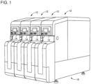
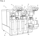
- the related system is configured from items including base 10, and four work modules (also referred to as "modules") 12 arranged on base 10.
- Fig. 1 shows a system with the external panels attached
- fig. 2 shows the system with some of the external panels open
- fig. 3 shows the system with the external panels removed.
- the side at which operation panel 14 is provided is referred to as the front side, and the "front and rear”, “left and right”, and “up and down” sides of the system are respectively the front and rear, left and right, and up and down when looking at the system from the front side. That is, the left and right direction in which the four modules 12 are arranged is the arrangement direction, and the front and rear direction is the intersecting direction, which is the direction perpendicular to (intersecting) the arrangement direction.
- Each of the four work modules shown in figs. 1 to 3 is a lathe module, which is a modularized lathe, that performs cutting processing on work W4 (refer to fig. 3 ) positioned at a work position using bite 20 held on head 18 by work W4 being rotated by spindle 16.
- the work is transferred between each module 12 by work transporting device 22.
- work transported by work transport device 22 is attached to a chuck, which is a holding tool attached to the tip of spindle 16 by work moving device 24.
- work for which processing by module 12 is complete is transferred from the chuck to work transporting device 22 by work moving device 24, and is transported to the next module 12 by work transporting device 22.
- work transporting attachment and detachment device 26 that is capable of performing both sets of work.
- This work transporting attachment and detachment device 26 is movable in the arrangement direction along pair of rails 28 attached to the front surface of base 10, such that work is able to be transported along multiple modules 12.
- work transporting attachment and detachment device 26 includes articulated arm 30, and chuck 32 provided at the leading end of arm 30 as a holding tool for holding work. That is, work transporting attachment and detachment device 26 extends arm 30 to the processing position of module 12, receives work from the processing position and attaches work at the processing position using chuck 32.
- W1 of fig. 2 and W4 of fig. 3 schematically represent work positioned at a set work position
- W2 of fig. 2 schematically represents work transferred across modules 12 by the transporting device
- W3 schematically represents the occupied space range of work while being moved to the work position inside each module 12.
- the four modules 12 have substantially the same shape, dimension, and structure and are closely arranged at a set arrangement pitch in the arrangement direction.
- the gap between each module 12 is 50 mm or less, and in actuality the four modules 12 are arranged with practically no gap between them.
- Each of the modules 12 has a general shape of a rectangular parallelepiped and the dimension in the right-left direction (hereinafter, sometimes referred to as "module width") is significantly smaller than the dimension in the front-rear direction (hereinafter, sometimes referred to as "module length").
- base 10 has substantially the same left-right dimension as the overall left-right dimension of four modules when the four modules are loaded on the base. That is, base 10 is just large enough in the left-right direction for four modules 12 to be loaded.
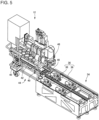
- Base 10 is configured from items including two base units 34 lined and affixed to each other. As shown in fig. 5 , two modules 12 are able to be loaded on each base unit 34. Each of the two base units 34 is standardized and both base units have the same shape, dimension, and structure.
- a quantity of rail pairs 36 corresponding to the quantity of modules 12 mounted on each base unit 34 that is, specifically, two rail pairs 36, are provided parallel to the arrangement direction.
- One rail pair 36 has a pair of rails 38 laid out at an interval extending in the intersecting direction (front-rear direction). Rails 38 mark the path along which module 12 moves when module 12 is pulled out.
- a pair of wheels 40 at each of the front and rear that is, two pairs of wheels 40, are rotatably held in bed 42.
- Module 12 is easily pulled out from base unit 34 in both directions, that is, in the frontwards direction or the rearwards direction, by the two pairs of wheels 40 rotating on the pair of rails 38. Note that, in fig. 2 the module 12 further to the right is pulled forward in the intersecting direction, and in fig. 3 the second module 12 from the right is pulled forward in the intersecting direction.
- modules 12 are able to be pulled all the way off base unit 34. Pulling out of modules 12 is shown in fig. 5 , which shows a module being pulled out from the rearwards direction using trolley 44.
- Trolley 44 includes pair of rails 46 with the same cross section and gap between them as pair of rails 36 provided on base unit 34; the pair of rails 46 are set against base 10 so as to extend the pair of rails 38. In that state, a portion or all of module 12 is able to be moved onto trolley 44.
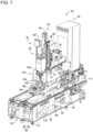
- each lathe module 12 is able to be removed from and loaded on base 10, such that exchange with another work module is possible, such as different work module 50 shown in figs. 6 and 7 .
- Work module 50 is a modularized machining center, and as described later in detail, performs cutting processing on work W5 fixedly held on a work table using a drill or endmill. In the descriptions below, work module 50 is sometimes referred to as drilling mill module 50.
- the machining system of the present embodiment of the present invention is a system in which at least one of the four lathe modules 12 of the connected system shown in figs . 1 to 3 is exchanged for drilling mill module 50.
- Drilling mill module 50 as a processing module uses the same bed 42 as the above lathe module 12, and has the same module width. That is, similar to lathe module 12, drilling mill module 50 has a module width significantly smaller than the dimension in the front-rear direction. Described below in detail is the configuration of drilling mill module 50 with a small module width as above, and the configuration of the machining system of the present embodiment.
- drilling mill module 50 is provided with bed 42 that rotatably holds multiple wheels 40, machining center 52 that is set on bed 42 and that performs processing work, and control box 54 that controls machining center 52.
- Machining center 52 is a so-called vertical machining center, and is provided with module main body 60 fixed on bed 42, main shaft head 62 the lower end of which holds a tool, head raising and lowering device 54 that moves main shaft head 62 in a vertical direction, head moving device 66 that moves main shaft head 62 in a horizontal plane by moving it in two perpendicular directions, and work table 68 that holds work W5.
- An upper section of module main body 60 supports head moving device 66 and head raising and lowering device 64.
- First slider 70 is supported on the upper section of module main body 60 so as to be slidable in the front-rear directions using pair of guide rails 72 provided on first slider 70 and multiple bearings 74 provided on module main body 60.
- First slider 70 is moved in the front and rear directions by a front and rear moving mechanism that includes a front and rear motor 76, a ball screw, and the like.
- second slider 80 is supported on first slider 70 so as to be slidable in left and right directions along pair of guide rails 82 provided on a front surface of first slider 70.
- Second slider 80 is moved in left and right directions by a left and right moving mechanism that includes a left and right motor 84, ball screw mechanism 86, and the like. That is, head moving device 66 is configured from items including first slider 70, pair of guide rails 72, bearings 74, a forwards and backwards moving mechanism, second slider 80, pair of guide rails 82, and a left and right moving mechanism.
- Main shaft head 62 is supported on second slider 80 so as to be slidable in left and right directions by pair of guide rails 90 provided on main shaft head 62 and multiple bearings provided on second slider 80.
- raising and lowering device 64 has main configuration elements such as head raising and lowering motor 94 and a ball screw mechanism, and main shaft head 62 is moved in a vertical direction by head raising and lowering device 64.
- Main shaft head 62 is supported at a position further forward than the front surface of module main body 60 by a configuration of the above head moving device 66 and head raising and lowering device 64.
- Main shaft head 62 includes a main shaft rotating device configured from a main body of main shaft 100 that extends vertically and the lower end of which holds a tool such as a drill or endmill, and main shaft rotating motor 102 that rotates main shaft 100 about its own axis.
- Work table 68 is supported in a state extending from the front surface to the rear surface of module main body 60. Machining center 52 is provided with table rotating device 106 that rotates work table 68 around an axis line that extends in the front-rear direction, and is capable of performing processing using a tool on work W5 held at an angle.
- the table rotating device may rotate the work table in a direction other than the front-rear direction, such as a left-right direction, or a direction between the front-rear direction and left-right direction wherein rotation occurs around an axis line that extends in a horizontal direction.
- the table rotating mechanism may perform rotation around a vertical axis, or around both a horizontal axis and a vertical axis.
- work is moved from an adjacent module to work table 68 by work transporting attachment and detachment device 26 that includes the articulated arm 30 shown in fig. 4 , and work for which processing by drilling mill module 50 is complete is moved from work table 68 to the next module.
- Drilling mill module 50 when performing cutting processing on work, performs cutting processing while applying coolant to the work. Also, shavings are generated during the cutting processing.
- the present machining system is configured to take account of this coolant and shavings.
- coolant tank 110 that stores coolant is built into base unit 34. And, entrance 112 for coolant and shavings to enter coolant tank 110 is provided on an upper surface of the front side of base unit 34 so as to be positioned below work table 68 provided in a forwards direction of module main body 60. Whilst omitting detailed descriptions, coolant tank 110 is provided with an internal screw conveyor such that coolant and shavings are separated and only the shavings are fed to the rear side of coolant tank 110.
- Coolant tank 110 protrudes from the rear side of base unit 34, and discharge duct 114 of the screw conveyor is provided on that protruding rear end section. That is, shavings that are generated at the position to the front side of module 50 are fed to the rear side by the screw conveyor provided inside coolant tank 110, past discharge duct 114, and discharged from the rear of this system.
- the shavings discharge device that discharges shavings received by base 10 from the rear of base 10 includes items such as coolant tank 110 and the screw conveyor.
- machining center 52 includes tool magazine 120 that stores multiple tools that attach to main shaft 100, and one of the multiple tools stored in tool magazine 120 is configured to be automatically exchangeable with a tool attached to main shaft 100.
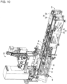
- Tool magazine 120 is stored inside module main body 60, and as shown in fig. 7 , during tool exchange, protrudes from the opening provided on the front surface of module main body 60. Note that, as shown in fig. 6 , during processing work by drilling mill module 50, that opening is covered by cover 124, such that coolant and shavings and the like are prevented from entering inside module main body 60 and getting on items such as tools stored in tool magazine 120.
- tool magazine 120 includes multiple tool holders (hereinafter, also sometimes referred to simply as "holders”) 130 that each hold a tool in an orientation extending in the vertical direction. That is, tool magazine 120 houses multiple tools such that the axis lines of each are parallel. Note that, as shown in fig. 8 (a) , usually, one or more holders 130 does not hold a tool, such that a holder is empty for receiving a tool attached to main shaft 100. T in fig. 8 schematically represents the empty storage range for tools held in each holder 130.
- tool magazine 120 includes roller chain 134 provided on two sprockets 132, and by the multiple tool holders 130 being fixed to roller chain 134, each of the multiple roller chains 134 is arranged along the elongated oval that is long in the intersecting direction. That is, tool magazine 120 has a small dimension in the left-right direction (arrangement direction) because the multiple tool holders are arranged along an elongated oval.
- Tool magazine 120 includes a sprocket drive motor for rotating sprockets 132 forwards (the right side in the figures), and reduction device 138 that transmits the rotation of the sprocket rotating motor to sprocket 132.
- Tool magazine 120 by rotating sprockets 132 using the sprocket rotating motor, is able to rotate roller chain 134 such that the multiple tool holders 130 are circulated. That is, the tool holder circulating mechanism is configured from items including the two sprockets 132, roller chain 134, a sprocket rotating motor, and reduction device 138.
- tool magazine 120 is able to move in the front and rear directions due to pair of guide rails 150 fixed inside module main body 60 extending in the front-rear direction, and bearings 152 as an guide engaging section fixed to the guide.
- machining center 52 is provided with magazine moving device 150 that moves tool magazine 120 in front and rear directions. Magazine moving device 150 is configured from items including a ball screw mechanism, and magazine moving motor 158 that rotates ball screw 156 of the ball screw mechanism. The nut of the ball screw mechanism is fixed to the bottom surface of tool magazine 120, and by rotating ball screw 156 using magazine rotating motor 158 fixed to module main body 60, the entire tool magazine 120 is able to be moved in the front and rear directions.
- Machining center 52 advances tool magazine 120 using magazine moving device 150, and the front end of tool magazine 120 protrudes from an opening in module main body 60. Then, in a state with tool magazine 120 positioned at the front limit a tool holder 130 used for exchange of the multiple tool holders 130, that is, the tool holder 130 positioned at the front limit, is positioned within the range in which main shaft 100 can be moved by head moving device 66, and tool shaft 100 tool exchange is performed with respect to the holder 130 positioned at the front limit.
- tool magazine 120 is advanced by magazine moving device 150, and main shaft 100 is moved to the exchange position by head moving device 66.
- a holder 130 not holding a tool is positioned at the front limit.
- Holder 130 is configured to grasp with two claws, and main shaft 100 is moved to the rear, the tool attached to main shaft 100 is engaged by the gap between the two claws of holder 130, and that tool is grasped by the holder 130.
- main shaft 100 is raised such that the tool is separated from main shaft 100.
- tool holders 130 are circulated and a tool to be attached to main shaft 100 is positioned at the front limit of tool magazine 120.
- main shaft 100 is lowered and the tool is attached to main shaft 100.
- main shaft 100 is moved forwards, and by retracting tool magazine 120, the tool is released from holder 130, thus completing tool exchange.
- drilling mill module 50 uses bed 42 similar to that of lathe module 12, in a similar manner to lathe module 12, drilling mill module 50 can be pulled out from base 10 along a path extending in the intersecting direction (front-rear direction).
- the drilling mill module 50 on the right is shown pulled out forwards.
- the pulling forward of drilling mill module 50 to the front as shown in fig. 9 is performed for maintenance of tool magazine 120, exchange of tool magazine 120 according to a work change, and the like.
- drilling mill module 50 is shown pulled out all the way off. By arranging in this state, overall maintenance of machining center 52 becomes easy to perform.
- tool magazine 120 is housed inside module main body 60, this machining system is more compact compared to a case in which tool magazine 120 is arranged outside of module main body 60. However, because tool magazine 120 is housed inside module main body 60, approaching tool magazine 120 is more difficult. But, as described above, with this machining system, because module 50 can be pulled out from base 10, it is easy to approach tool magazine 120.
- tool magazine 120 has tool holders 130 arranged along an elongated oval that is long in the intersecting direction (front-rear direction).
- the direction of tool magazine 120 in the arrangement direction is relatively small, meaning the width of drilling mill module 50 in the arrangement direction is small.
- this machining system is configured such that, when exchanging a tool attached to main shaft 100, tool magazine is moved by magazine moving device 150 to a range in which tool shaft 100 can be moved. Thus, there is no need to widen the moving range of main shaft 100 for tool exchange, meaning that drilling mill module 50 can be compact.
- 10 base; 12: work module (lathe module) ; 26: work transporting attachment and detachment device; 34: base unit; 36: pair of rails; 38: rail; 40: wheel; 42: bed; 44: trolley; 46: rail; 50: drilling mill module (processing module); 52: machining center; 60: module main body; 62: main shaft head; 64: head raising and lowering device; 66: head moving device; 68: work table; 70: first slider; 76: front and rear motor; 80: second slider; 84: left and right moving motor; 94: head raising and lowering motor; 100: main shaft; 102:main shaft rotating motor; 106: table rotating device; 110: coolant tank; 112: entrance; 114: discharge duct; 120: tool magazine; 124: cover; 130: tool holder; 132: sprocket; 134: roller chain; 150: guide rail; 152: bearing (guide engaging section) ; 156: ball screw; 158: magazine moving motor
Landscapes
- Engineering & Computer Science (AREA)
- Mechanical Engineering (AREA)
- Physics & Mathematics (AREA)
- Optics & Photonics (AREA)
- Automatic Tool Replacement In Machine Tools (AREA)
- Machine Tool Units (AREA)
- Multi-Process Working Machines And Systems (AREA)
Claims (8)
- Ein Bearbeitungssystem, umfassend:eine Basis (10);einen Wagen (44),mehrere Arbeitsmodule (12), die in einer Anordnungsrichtung auf der Basis (10) angeordnet sind, wobei mindestens eines der mehreren Arbeitsmodule (12) ein Bearbeitungsmodul (50) ist, das ein Werkstück mit einem Werkzeug bearbeitet und mit einem Hauptschaftkopf (62) versehen ist, der eine Hauptwelle, an der ein Werkzeug befestigt ist, und eine Hauptwellendrehvorrichtung, die die Hauptwelle (100) dreht, enthälteinen Kopfhebe- und -senkvorrichtung (64), die den Hauptschaftkopf (62) in einer vertikalen Richtung bewegt;eine Kopfbewegungsvorrichtung (66), die den Hauptschaftkopf (62) in einer horizontalen Ebene bewegt, indem sie ihn in zwei senkrechten Richtungen bewegt; undeinen Arbeitstisch (68), der ein Werkstück hält;das Bearbeitungsmodul (50) konfiguriert ist, ausgehend von einer eingestellten Arbeitsposition vorwärts auf der Basis (10) gezogen werden zu können und unter Verwendung des Wagens (44) rückwärts von der Basis (10) gezogen werden zu können, so dass ein Teil oder das gesamte Arbeitsmodul (12) ausgehend von der eingestellten Arbeitsposition entlang eines Weges, der sich in einer Schnittrichtung erstreckt, die eine Richtung senkrecht zu der Anordnungsrichtung ist, auf den Wagen (44) bewegt wird, wobei in einem Fall, in dem eine der beiden Richtungen, die einander in der Schnittrichtung gegenüberliegen, als vorwärts definiert ist und die andere Richtung als rückwärts definiert ist, der Arbeitstisch (68) an der Vorderseite des Bearbeitungsmoduls (50) angeordnet ist.
- Das Bearbeitungssystem gemäß Anspruch 1, wobeidas Bearbeitungsmodul (50) ein Werkzeugmagazin (120) enthält, in dem mehrere an der Hauptwelle anzubringende Werkzeuge gespeichert sind, und konfiguriert ist, das an der Hauptwelle (100) angebrachte Werkzeug automatisch gegen eines der mehreren im Werkzeugmagazin (120) gespeicherten Werkzeuge auszutauschen,das Werkzeugmagazin (120) mehrere Werkzeughalter (130) enthält, die jeweils konfiguriert sind, ein Werkzeug zu halten und entlang einer länglichen Ellipse in der Schnittrichtung angeordnet sind, und einen Werkzeughalter-Umlaufmechanismus, der konfiguriert ist, die mehreren Werkzeughalter (130) umlaufen zu lassen.
- Das Bearbeitungssystem gemäß Anspruch 2, wobeidas Bearbeitungsmodul (50) umfassteinen Modulhauptkörper (60), wobei die Kopfhebe- und -senkvorrichtung (64) an einem oberen Abschnitt des Modulhauptkörpers (60) gehalten wird und das Werkzeugmagazin (120) im Inneren des Modulhauptkörpers (60) untergebracht ist, undeine Magazinbewegungsvorrichtung, die das Werkzeugmagazin (120) in der Schnittrichtung bewegt und beim Durchführen eines Werkzeugwechsels das Werkzeugmagazin (120) so vorschiebt, dass es von einer Seitenfläche des Modulhauptkörpers (60) in der Schnittrichtung vorsteht, und einen der mehreren Werkzeughalter (130), die zum Zuführen eines Werkzeugs zum Austausch verwendet werden, in einem Bereich positioniert, in dem die Hauptwelle (100) durch die Kopfbewegungsvorrichtung (66) bewegt werden kann.
- Das Bearbeitungssystem gemäß einem der Ansprüche 1 bis 3, wobei
die mehreren Arbeitsmodule (12) auf der Basis (10) in Anordnungsrichtung dicht nebeneinander angeordnet sind. - T Das Bearbeitungssystem gemäß einem der Ansprüche 1 bis 4, wobei
jedes der mehreren Arbeitsmodule (12) in beide Richtungen entgegengesetzt zur Schnittrichtung ausgezogen werden kann. - Das Bearbeitungssystem gemäß einem der Ansprüche 1 bis 5, wobeidas Bearbeitungsmodul (50) ein Paar Räder (40) umfasst, unddie Basis (10) ein Paar Schienen (46) aufweist, die sich in der Schnittrichtung erstrecken, wobeidas Bearbeitungsmodul (50) konfiguriert ist, von der Basis (10) entlang des Weges durch das Paar von Rädern (40) des Bearbeitungsmoduls (50) gezogen zu werden, die sich entlang des Paares von Schienen (46) drehen.
- Das Bearbeitungssystem gemäß einem der Ansprüche 1 bis 6, wobei
das Bearbeitungsmodul (50) mit einer Tischdrehvorrichtung (106) versehen ist, die den Arbeitstisch (68) um mindestens eine von einer vertikalen Achse, die sich in einer vertikalen Richtung erstreckt, oder einer horizontalen Achse, die sich in einer horizontalen Richtung erstreckt, dreht. - T Das Bearbeitungssystem gemäß einem der Ansprüche 1 bis 7, wobei
die Basis (12) konfiguriert ist, Späne, die durch die Bearbeitung des Werkstücks durch das Bearbeitungsmodul (50) erzeugt werden, in das Innere der Basis (12) aufzunehmen, und das Bearbeitungssystem eine Späneabgabevorrichtung (114) enthält, die konfiguriert ist, die von der Basis (12) aufgenommenen Späne von der Rückseite der Basis abzugeben.
Applications Claiming Priority (1)
| Application Number | Priority Date | Filing Date | Title |
|---|---|---|---|
| PCT/JP2014/071758 WO2016027325A1 (ja) | 2014-08-20 | 2014-08-20 | 機械工作システム |
Publications (3)
| Publication Number | Publication Date |
|---|---|
| EP3184239A1 EP3184239A1 (de) | 2017-06-28 |
| EP3184239A4 EP3184239A4 (de) | 2017-08-23 |
| EP3184239B1 true EP3184239B1 (de) | 2024-08-28 |
Family
ID=55350304
Family Applications (1)
| Application Number | Title | Priority Date | Filing Date |
|---|---|---|---|
| EP14899988.1A Active EP3184239B1 (de) | 2014-08-20 | 2014-08-20 | Bearbeitungssystem |
Country Status (5)
| Country | Link |
|---|---|
| US (1) | US10226847B2 (de) |
| EP (1) | EP3184239B1 (de) |
| JP (1) | JP6697388B2 (de) |
| CN (1) | CN106660186B (de) |
| WO (1) | WO2016027325A1 (de) |
Families Citing this family (11)
| Publication number | Priority date | Publication date | Assignee | Title |
|---|---|---|---|---|
| CN106573352B (zh) * | 2014-08-20 | 2019-03-19 | 株式会社富士 | 加工中心 |
| CN107073670B (zh) * | 2014-10-17 | 2019-04-19 | 株式会社富士 | 加工机械的基座构造及构筑加工机械生产线的基座设置方法 |
| US10058967B2 (en) * | 2014-10-24 | 2018-08-28 | Fuji Machine Mfg. Co., Ltd. | Manufacturing system |
| JP6637989B2 (ja) * | 2015-10-20 | 2020-01-29 | 株式会社Fuji | 機械加工システム |
| CN105773632B (zh) * | 2016-03-17 | 2017-10-31 | 浙江大学 | 一种自动钻铆机的多功能末端执行器 |
| US11407074B2 (en) * | 2016-09-14 | 2022-08-09 | Fuji Corporation | Processing machine line |
| WO2018229906A1 (ja) * | 2017-06-14 | 2018-12-20 | 株式会社Fuji | レール式走行構造および加工機械ライン |
| JP7098234B2 (ja) * | 2018-06-20 | 2022-07-11 | 株式会社ディスコ | 加工設備 |
| DE202019002338U1 (de) * | 2019-05-29 | 2020-09-01 | Imes-Icore Gmbh | Dentalbearbeitungsmaschine |
| WO2021053705A1 (ja) * | 2019-09-17 | 2021-03-25 | 株式会社Fuji | 移載台および加工モジュールの移載構造 |
| CN115816084A (zh) * | 2022-11-29 | 2023-03-21 | 安徽维卡门窗股份有限公司 | 一种异形铝型材生产定位装置及其使用方法 |
Family Cites Families (21)
| Publication number | Priority date | Publication date | Assignee | Title |
|---|---|---|---|---|
| US4358888A (en) * | 1980-10-16 | 1982-11-16 | Kearney & Trecker Corporation | Automatic tool changer with internal tool storage magazine |
| JPS58211844A (ja) * | 1983-05-09 | 1983-12-09 | Hitachi Seiki Co Ltd | 工作機械における搬送装置 |
| AT392050B (de) * | 1984-02-06 | 1991-01-10 | Sticht Walter | Fertigungsanlage mit mehreren einzelstationen |
| JPH0247140U (de) * | 1988-09-26 | 1990-03-30 | ||
| JP3642069B2 (ja) * | 1994-03-09 | 2005-04-27 | 豊田工機株式会社 | 自動工具交換装置 |
| JPH09309042A (ja) * | 1996-05-23 | 1997-12-02 | Makino Milling Mach Co Ltd | 工作機械 |
| JP2002356216A (ja) * | 2001-05-31 | 2002-12-10 | Enomoto Kogyo Kk | 折りたたみ式チップコンベア |
| DE102004029665A1 (de) * | 2004-03-30 | 2005-10-27 | Continental Teves Ag & Co. Ohg | Modulares Transfersystem für Werkstücke |
| JP4789103B2 (ja) | 2004-08-06 | 2011-10-12 | セイコーインスツル株式会社 | 生産ライン |
| JP4061553B2 (ja) * | 2005-03-18 | 2008-03-19 | ホーコス株式会社 | 工作機械 |
| EP2332690A3 (de) | 2005-03-18 | 2013-06-26 | Horkos Corp | Werkzeugmaschine |
| FR2892040B1 (fr) * | 2005-10-18 | 2010-01-29 | Ys Etudes Et Ind | Installation modulaire automatisee et module automatise |
| DE102006032121A1 (de) * | 2006-07-04 | 2008-01-10 | Teamtechnik Maschinen Und Anlagen Gmbh | Bearbeitungsvorrichtung |
| JP4849403B2 (ja) * | 2006-10-30 | 2012-01-11 | セイコーインスツル株式会社 | 工程設計支援装置、工程設計支援方法、及び工程設計支援プログラム |
| DE102007008219A1 (de) * | 2007-02-20 | 2008-08-21 | Robert Bosch Gmbh | Bearbeitungsplatz und Bearbeitungsstraße |
| CN201346715Y (zh) * | 2009-01-24 | 2009-11-18 | 苏州江南电梯(集团)有限公司 | 具有复合式刀库的加工中心 |
| JP4420980B2 (ja) * | 2009-07-29 | 2010-02-24 | 富士機械製造株式会社 | 電子回路部品装着システム |
| JP6127244B2 (ja) * | 2011-12-01 | 2017-05-17 | 国立研究開発法人産業技術総合研究所 | 移動型製造装置の設置機構、固定構造及び移動型製造装置 |
| DE102012107627A1 (de) * | 2012-08-20 | 2014-02-20 | CATENA UG (haftungsbeschränkt) | Modulare Werkzeugmaschine |
| WO2015037148A1 (ja) * | 2013-09-13 | 2015-03-19 | 富士機械製造株式会社 | 機械工作システム |
| DE102016007407A1 (de) * | 2016-06-19 | 2017-12-21 | Csm Maschinen Gmbh | multifunktionales Bearbeitungszentrum |
-
2014
- 2014-08-20 CN CN201480081220.XA patent/CN106660186B/zh active Active
- 2014-08-20 JP JP2016543527A patent/JP6697388B2/ja active Active
- 2014-08-20 US US15/501,898 patent/US10226847B2/en active Active
- 2014-08-20 WO PCT/JP2014/071758 patent/WO2016027325A1/ja not_active Ceased
- 2014-08-20 EP EP14899988.1A patent/EP3184239B1/de active Active
Also Published As
| Publication number | Publication date |
|---|---|
| CN106660186B (zh) | 2019-07-12 |
| JP6697388B2 (ja) | 2020-05-20 |
| EP3184239A4 (de) | 2017-08-23 |
| CN106660186A (zh) | 2017-05-10 |
| US10226847B2 (en) | 2019-03-12 |
| US20170225285A1 (en) | 2017-08-10 |
| JPWO2016027325A1 (ja) | 2017-06-01 |
| EP3184239A1 (de) | 2017-06-28 |
| WO2016027325A1 (ja) | 2016-02-25 |
Similar Documents
| Publication | Publication Date | Title |
|---|---|---|
| US10226847B2 (en) | Machining system | |
| US10207381B2 (en) | Machine tool having a number of multispindle spindle assemblies | |
| US9914189B2 (en) | Machine tool having a workpiece changing device | |
| US10220478B2 (en) | Machining center | |
| US20080271304A1 (en) | Machine Tool | |
| JP2006326803A (ja) | 工作機械 | |
| WO2016059738A1 (ja) | 横型工作機械 | |
| JP6420349B2 (ja) | マシニングセンタ | |
| US10099334B2 (en) | Machining system | |
| US20160214227A1 (en) | Machining system | |
| US9919398B2 (en) | Machining system | |
| JP5732855B2 (ja) | ワーク搬送装置 | |
| JP2005034933A (ja) | マシニングセンタ | |
| CN106794566B (zh) | 制造系统 | |
| KR101638702B1 (ko) | 자동공구교환장치 | |
| JP6964157B2 (ja) | 機械工作システム | |
| CN109689287A (zh) | 加工机械生产线 | |
| JP2008142891A (ja) | マシニングセンタ | |
| JP6656262B2 (ja) | 機械加工システム | |
| US20250332672A1 (en) | Tool transport system and method for exchanging tools at machine tools | |
| JP6637989B2 (ja) | 機械加工システム | |
| EP4667150A1 (de) | Magazinvorrichtung und werkzeugmaschine damit | |
| CZ289281B6 (cs) | Obráběcí stroj | |
| JP6876198B2 (ja) | 工作機械 | |
| WO2003103890A1 (de) | Werkzeugmaschine mit ladevorrichtung |
Legal Events
| Date | Code | Title | Description |
|---|---|---|---|
| STAA | Information on the status of an ep patent application or granted ep patent |
Free format text: STATUS: THE INTERNATIONAL PUBLICATION HAS BEEN MADE |
|
| PUAI | Public reference made under article 153(3) epc to a published international application that has entered the european phase |
Free format text: ORIGINAL CODE: 0009012 |
|
| STAA | Information on the status of an ep patent application or granted ep patent |
Free format text: STATUS: REQUEST FOR EXAMINATION WAS MADE |
|
| 17P | Request for examination filed |
Effective date: 20170214 |
|
| AK | Designated contracting states |
Kind code of ref document: A1 Designated state(s): AL AT BE BG CH CY CZ DE DK EE ES FI FR GB GR HR HU IE IS IT LI LT LU LV MC MK MT NL NO PL PT RO RS SE SI SK SM TR |
|
| AX | Request for extension of the european patent |
Extension state: BA ME |
|
| A4 | Supplementary search report drawn up and despatched |
Effective date: 20170726 |
|
| RIC1 | Information provided on ipc code assigned before grant |
Ipc: B23Q 1/00 20060101ALI20170720BHEP Ipc: B23Q 37/00 20060101AFI20170720BHEP Ipc: B23P 23/00 20060101ALI20170720BHEP |
|
| DAX | Request for extension of the european patent (deleted) | ||
| STAA | Information on the status of an ep patent application or granted ep patent |
Free format text: STATUS: EXAMINATION IS IN PROGRESS |
|
| RAP1 | Party data changed (applicant data changed or rights of an application transferred) |
Owner name: FUJI CORPORATION |
|
| 17Q | First examination report despatched |
Effective date: 20181018 |
|
| RIN1 | Information on inventor provided before grant (corrected) |
Inventor name: SUZUYAMA, SHIGEFUMI Inventor name: ASAKAWA, KAZUYA Inventor name: MIZUTA, KENJI |
|
| P01 | Opt-out of the competence of the unified patent court (upc) registered |
Effective date: 20230328 |
|
| GRAP | Despatch of communication of intention to grant a patent |
Free format text: ORIGINAL CODE: EPIDOSNIGR1 |
|
| RAP3 | Party data changed (applicant data changed or rights of an application transferred) |
Owner name: FUJI CORPORATION |
|
| RIN1 | Information on inventor provided before grant (corrected) |
Inventor name: SUZUYAMA, SHIGEFUMI Inventor name: MIZUTA, KENJI Inventor name: ASAKAWA, KAZUYA |
|
| STAA | Information on the status of an ep patent application or granted ep patent |
Free format text: STATUS: GRANT OF PATENT IS INTENDED |
|
| INTG | Intention to grant announced |
Effective date: 20240425 |
|
| GRAS | Grant fee paid |
Free format text: ORIGINAL CODE: EPIDOSNIGR3 |
|
| GRAA | (expected) grant |
Free format text: ORIGINAL CODE: 0009210 |
|
| STAA | Information on the status of an ep patent application or granted ep patent |
Free format text: STATUS: THE PATENT HAS BEEN GRANTED |
|
| AK | Designated contracting states |
Kind code of ref document: B1 Designated state(s): AL AT BE BG CH CY CZ DE DK EE ES FI FR GB GR HR HU IE IS IT LI LT LU LV MC MK MT NL NO PL PT RO RS SE SI SK SM TR |
|
| REG | Reference to a national code |
Ref country code: GB Ref legal event code: FG4D |
|
| REG | Reference to a national code |
Ref country code: CH Ref legal event code: EP |
|
| REG | Reference to a national code |
Ref country code: DE Ref legal event code: R096 Ref document number: 602014090781 Country of ref document: DE |
|
| REG | Reference to a national code |
Ref country code: IE Ref legal event code: FG4D |
|
| REG | Reference to a national code |
Ref country code: LT Ref legal event code: MG9D |
|
| PG25 | Lapsed in a contracting state [announced via postgrant information from national office to epo] |
Ref country code: NO Free format text: LAPSE BECAUSE OF FAILURE TO SUBMIT A TRANSLATION OF THE DESCRIPTION OR TO PAY THE FEE WITHIN THE PRESCRIBED TIME-LIMIT Effective date: 20241128 |
|
| REG | Reference to a national code |
Ref country code: AT Ref legal event code: MK05 Ref document number: 1717437 Country of ref document: AT Kind code of ref document: T Effective date: 20240828 |
|
| PG25 | Lapsed in a contracting state [announced via postgrant information from national office to epo] |
Ref country code: PL Free format text: LAPSE BECAUSE OF FAILURE TO SUBMIT A TRANSLATION OF THE DESCRIPTION OR TO PAY THE FEE WITHIN THE PRESCRIBED TIME-LIMIT Effective date: 20240828 Ref country code: NL Free format text: LAPSE BECAUSE OF FAILURE TO SUBMIT A TRANSLATION OF THE DESCRIPTION OR TO PAY THE FEE WITHIN THE PRESCRIBED TIME-LIMIT Effective date: 20240828 Ref country code: GR Free format text: LAPSE BECAUSE OF FAILURE TO SUBMIT A TRANSLATION OF THE DESCRIPTION OR TO PAY THE FEE WITHIN THE PRESCRIBED TIME-LIMIT Effective date: 20241129 Ref country code: PT Free format text: LAPSE BECAUSE OF FAILURE TO SUBMIT A TRANSLATION OF THE DESCRIPTION OR TO PAY THE FEE WITHIN THE PRESCRIBED TIME-LIMIT Effective date: 20241230 Ref country code: FI Free format text: LAPSE BECAUSE OF FAILURE TO SUBMIT A TRANSLATION OF THE DESCRIPTION OR TO PAY THE FEE WITHIN THE PRESCRIBED TIME-LIMIT Effective date: 20240828 |
|
| PG25 | Lapsed in a contracting state [announced via postgrant information from national office to epo] |
Ref country code: BG Free format text: LAPSE BECAUSE OF FAILURE TO SUBMIT A TRANSLATION OF THE DESCRIPTION OR TO PAY THE FEE WITHIN THE PRESCRIBED TIME-LIMIT Effective date: 20240828 |
|
| PG25 | Lapsed in a contracting state [announced via postgrant information from national office to epo] |
Ref country code: LV Free format text: LAPSE BECAUSE OF FAILURE TO SUBMIT A TRANSLATION OF THE DESCRIPTION OR TO PAY THE FEE WITHIN THE PRESCRIBED TIME-LIMIT Effective date: 20240828 |
|
| REG | Reference to a national code |
Ref country code: NL Ref legal event code: MP Effective date: 20240828 |
|
| PG25 | Lapsed in a contracting state [announced via postgrant information from national office to epo] |
Ref country code: IS Free format text: LAPSE BECAUSE OF FAILURE TO SUBMIT A TRANSLATION OF THE DESCRIPTION OR TO PAY THE FEE WITHIN THE PRESCRIBED TIME-LIMIT Effective date: 20241228 Ref country code: AT Free format text: LAPSE BECAUSE OF FAILURE TO SUBMIT A TRANSLATION OF THE DESCRIPTION OR TO PAY THE FEE WITHIN THE PRESCRIBED TIME-LIMIT Effective date: 20240828 |
|
| PG25 | Lapsed in a contracting state [announced via postgrant information from national office to epo] |
Ref country code: HR Free format text: LAPSE BECAUSE OF FAILURE TO SUBMIT A TRANSLATION OF THE DESCRIPTION OR TO PAY THE FEE WITHIN THE PRESCRIBED TIME-LIMIT Effective date: 20240828 |
|
| PG25 | Lapsed in a contracting state [announced via postgrant information from national office to epo] |
Ref country code: RS Free format text: LAPSE BECAUSE OF FAILURE TO SUBMIT A TRANSLATION OF THE DESCRIPTION OR TO PAY THE FEE WITHIN THE PRESCRIBED TIME-LIMIT Effective date: 20241128 Ref country code: ES Free format text: LAPSE BECAUSE OF FAILURE TO SUBMIT A TRANSLATION OF THE DESCRIPTION OR TO PAY THE FEE WITHIN THE PRESCRIBED TIME-LIMIT Effective date: 20240828 |
|
| PG25 | Lapsed in a contracting state [announced via postgrant information from national office to epo] |
Ref country code: RS Free format text: LAPSE BECAUSE OF FAILURE TO SUBMIT A TRANSLATION OF THE DESCRIPTION OR TO PAY THE FEE WITHIN THE PRESCRIBED TIME-LIMIT Effective date: 20241128 Ref country code: PT Free format text: LAPSE BECAUSE OF FAILURE TO SUBMIT A TRANSLATION OF THE DESCRIPTION OR TO PAY THE FEE WITHIN THE PRESCRIBED TIME-LIMIT Effective date: 20241230 Ref country code: PL Free format text: LAPSE BECAUSE OF FAILURE TO SUBMIT A TRANSLATION OF THE DESCRIPTION OR TO PAY THE FEE WITHIN THE PRESCRIBED TIME-LIMIT Effective date: 20240828 Ref country code: NO Free format text: LAPSE BECAUSE OF FAILURE TO SUBMIT A TRANSLATION OF THE DESCRIPTION OR TO PAY THE FEE WITHIN THE PRESCRIBED TIME-LIMIT Effective date: 20241128 Ref country code: NL Free format text: LAPSE BECAUSE OF FAILURE TO SUBMIT A TRANSLATION OF THE DESCRIPTION OR TO PAY THE FEE WITHIN THE PRESCRIBED TIME-LIMIT Effective date: 20240828 Ref country code: LV Free format text: LAPSE BECAUSE OF FAILURE TO SUBMIT A TRANSLATION OF THE DESCRIPTION OR TO PAY THE FEE WITHIN THE PRESCRIBED TIME-LIMIT Effective date: 20240828 Ref country code: IS Free format text: LAPSE BECAUSE OF FAILURE TO SUBMIT A TRANSLATION OF THE DESCRIPTION OR TO PAY THE FEE WITHIN THE PRESCRIBED TIME-LIMIT Effective date: 20241228 Ref country code: HR Free format text: LAPSE BECAUSE OF FAILURE TO SUBMIT A TRANSLATION OF THE DESCRIPTION OR TO PAY THE FEE WITHIN THE PRESCRIBED TIME-LIMIT Effective date: 20240828 Ref country code: GR Free format text: LAPSE BECAUSE OF FAILURE TO SUBMIT A TRANSLATION OF THE DESCRIPTION OR TO PAY THE FEE WITHIN THE PRESCRIBED TIME-LIMIT Effective date: 20241129 Ref country code: FI Free format text: LAPSE BECAUSE OF FAILURE TO SUBMIT A TRANSLATION OF THE DESCRIPTION OR TO PAY THE FEE WITHIN THE PRESCRIBED TIME-LIMIT Effective date: 20240828 Ref country code: ES Free format text: LAPSE BECAUSE OF FAILURE TO SUBMIT A TRANSLATION OF THE DESCRIPTION OR TO PAY THE FEE WITHIN THE PRESCRIBED TIME-LIMIT Effective date: 20240828 Ref country code: BG Free format text: LAPSE BECAUSE OF FAILURE TO SUBMIT A TRANSLATION OF THE DESCRIPTION OR TO PAY THE FEE WITHIN THE PRESCRIBED TIME-LIMIT Effective date: 20240828 Ref country code: AT Free format text: LAPSE BECAUSE OF FAILURE TO SUBMIT A TRANSLATION OF THE DESCRIPTION OR TO PAY THE FEE WITHIN THE PRESCRIBED TIME-LIMIT Effective date: 20240828 |
|
| PG25 | Lapsed in a contracting state [announced via postgrant information from national office to epo] |
Ref country code: DK Free format text: LAPSE BECAUSE OF FAILURE TO SUBMIT A TRANSLATION OF THE DESCRIPTION OR TO PAY THE FEE WITHIN THE PRESCRIBED TIME-LIMIT Effective date: 20240828 Ref country code: SM Free format text: LAPSE BECAUSE OF FAILURE TO SUBMIT A TRANSLATION OF THE DESCRIPTION OR TO PAY THE FEE WITHIN THE PRESCRIBED TIME-LIMIT Effective date: 20240828 Ref country code: RO Free format text: LAPSE BECAUSE OF FAILURE TO SUBMIT A TRANSLATION OF THE DESCRIPTION OR TO PAY THE FEE WITHIN THE PRESCRIBED TIME-LIMIT Effective date: 20240828 |
|
| PG25 | Lapsed in a contracting state [announced via postgrant information from national office to epo] |
Ref country code: EE Free format text: LAPSE BECAUSE OF FAILURE TO SUBMIT A TRANSLATION OF THE DESCRIPTION OR TO PAY THE FEE WITHIN THE PRESCRIBED TIME-LIMIT Effective date: 20240828 |
|
| PG25 | Lapsed in a contracting state [announced via postgrant information from national office to epo] |
Ref country code: CZ Free format text: LAPSE BECAUSE OF FAILURE TO SUBMIT A TRANSLATION OF THE DESCRIPTION OR TO PAY THE FEE WITHIN THE PRESCRIBED TIME-LIMIT Effective date: 20240828 |
|
| PG25 | Lapsed in a contracting state [announced via postgrant information from national office to epo] |
Ref country code: IT Free format text: LAPSE BECAUSE OF FAILURE TO SUBMIT A TRANSLATION OF THE DESCRIPTION OR TO PAY THE FEE WITHIN THE PRESCRIBED TIME-LIMIT Effective date: 20240828 Ref country code: SK Free format text: LAPSE BECAUSE OF FAILURE TO SUBMIT A TRANSLATION OF THE DESCRIPTION OR TO PAY THE FEE WITHIN THE PRESCRIBED TIME-LIMIT Effective date: 20240828 |
|
| REG | Reference to a national code |
Ref country code: DE Ref legal event code: R097 Ref document number: 602014090781 Country of ref document: DE |
|
| PLBE | No opposition filed within time limit |
Free format text: ORIGINAL CODE: 0009261 |
|
| STAA | Information on the status of an ep patent application or granted ep patent |
Free format text: STATUS: NO OPPOSITION FILED WITHIN TIME LIMIT |
|
| 26N | No opposition filed |
Effective date: 20250530 |
|
| PG25 | Lapsed in a contracting state [announced via postgrant information from national office to epo] |
Ref country code: SE Free format text: LAPSE BECAUSE OF FAILURE TO SUBMIT A TRANSLATION OF THE DESCRIPTION OR TO PAY THE FEE WITHIN THE PRESCRIBED TIME-LIMIT Effective date: 20240828 |
|
| REG | Reference to a national code |
Ref country code: DE Ref legal event code: R119 Ref document number: 602014090781 Country of ref document: DE |
|
| REG | Reference to a national code |
Ref country code: CH Ref legal event code: H13 Free format text: ST27 STATUS EVENT CODE: U-0-0-H10-H13 (AS PROVIDED BY THE NATIONAL OFFICE) Effective date: 20260324 |
|
| PG25 | Lapsed in a contracting state [announced via postgrant information from national office to epo] |
Ref country code: MC Free format text: LAPSE BECAUSE OF FAILURE TO SUBMIT A TRANSLATION OF THE DESCRIPTION OR TO PAY THE FEE WITHIN THE PRESCRIBED TIME-LIMIT Effective date: 20240828 |
|
| PG25 | Lapsed in a contracting state [announced via postgrant information from national office to epo] |
Ref country code: LU Free format text: LAPSE BECAUSE OF NON-PAYMENT OF DUE FEES Effective date: 20250820 |
|
| PG25 | Lapsed in a contracting state [announced via postgrant information from national office to epo] |
Ref country code: CH Free format text: LAPSE BECAUSE OF NON-PAYMENT OF DUE FEES Effective date: 20250831 |
|
| GBPC | Gb: european patent ceased through non-payment of renewal fee |
Effective date: 20250820 |