EP3184331B1 - Dispositif de suspension pneumatique - Google Patents
Dispositif de suspension pneumatique Download PDFInfo
- Publication number
- EP3184331B1 EP3184331B1 EP16199953.7A EP16199953A EP3184331B1 EP 3184331 B1 EP3184331 B1 EP 3184331B1 EP 16199953 A EP16199953 A EP 16199953A EP 3184331 B1 EP3184331 B1 EP 3184331B1
- Authority
- EP
- European Patent Office
- Prior art keywords
- air
- compressed air
- inlet
- outlet
- pressure
- Prior art date
- Legal status (The legal status is an assumption and is not a legal conclusion. Google has not performed a legal analysis and makes no representation as to the accuracy of the status listed.)
- Active
Links
Images


Classifications
-
- B—PERFORMING OPERATIONS; TRANSPORTING
- B60—VEHICLES IN GENERAL
- B60G—VEHICLE SUSPENSION ARRANGEMENTS
- B60G17/00—Resilient suspensions having means for adjusting the spring or vibration-damper characteristics, for regulating the distance between a supporting surface and a sprung part of vehicle or for locking suspension during use to meet varying vehicular or surface conditions, e.g. due to speed or load
- B60G17/015—Resilient suspensions having means for adjusting the spring or vibration-damper characteristics, for regulating the distance between a supporting surface and a sprung part of vehicle or for locking suspension during use to meet varying vehicular or surface conditions, e.g. due to speed or load the regulating means comprising electric or electronic elements
- B60G17/0152—Resilient suspensions having means for adjusting the spring or vibration-damper characteristics, for regulating the distance between a supporting surface and a sprung part of vehicle or for locking suspension during use to meet varying vehicular or surface conditions, e.g. due to speed or load the regulating means comprising electric or electronic elements characterised by the action on a particular type of suspension unit
- B60G17/0155—Resilient suspensions having means for adjusting the spring or vibration-damper characteristics, for regulating the distance between a supporting surface and a sprung part of vehicle or for locking suspension during use to meet varying vehicular or surface conditions, e.g. due to speed or load the regulating means comprising electric or electronic elements characterised by the action on a particular type of suspension unit pneumatic unit
-
- B—PERFORMING OPERATIONS; TRANSPORTING
- B60—VEHICLES IN GENERAL
- B60G—VEHICLE SUSPENSION ARRANGEMENTS
- B60G17/00—Resilient suspensions having means for adjusting the spring or vibration-damper characteristics, for regulating the distance between a supporting surface and a sprung part of vehicle or for locking suspension during use to meet varying vehicular or surface conditions, e.g. due to speed or load
- B60G17/02—Spring characteristics, e.g. mechanical springs and mechanical adjusting means
- B60G17/04—Spring characteristics, e.g. mechanical springs and mechanical adjusting means fluid spring characteristics
- B60G17/052—Pneumatic spring characteristics
- B60G17/0523—Regulating distributors or valves for pneumatic springs
- B60G17/0525—Height adjusting or levelling valves
-
- B—PERFORMING OPERATIONS; TRANSPORTING
- B60—VEHICLES IN GENERAL
- B60G—VEHICLE SUSPENSION ARRANGEMENTS
- B60G17/00—Resilient suspensions having means for adjusting the spring or vibration-damper characteristics, for regulating the distance between a supporting surface and a sprung part of vehicle or for locking suspension during use to meet varying vehicular or surface conditions, e.g. due to speed or load
- B60G17/02—Spring characteristics, e.g. mechanical springs and mechanical adjusting means
- B60G17/04—Spring characteristics, e.g. mechanical springs and mechanical adjusting means fluid spring characteristics
- B60G17/052—Pneumatic spring characteristics
- B60G17/0523—Regulating distributors or valves for pneumatic springs
- B60G17/0528—Pressure regulating or air filling valves
-
- B—PERFORMING OPERATIONS; TRANSPORTING
- B60—VEHICLES IN GENERAL
- B60G—VEHICLE SUSPENSION ARRANGEMENTS
- B60G17/00—Resilient suspensions having means for adjusting the spring or vibration-damper characteristics, for regulating the distance between a supporting surface and a sprung part of vehicle or for locking suspension during use to meet varying vehicular or surface conditions, e.g. due to speed or load
- B60G17/02—Spring characteristics, e.g. mechanical springs and mechanical adjusting means
- B60G17/04—Spring characteristics, e.g. mechanical springs and mechanical adjusting means fluid spring characteristics
- B60G17/056—Regulating distributors or valves for hydropneumatic systems
- B60G17/0565—Height adjusting valves
-
- B—PERFORMING OPERATIONS; TRANSPORTING
- B60—VEHICLES IN GENERAL
- B60G—VEHICLE SUSPENSION ARRANGEMENTS
- B60G2202/00—Indexing codes relating to the type of spring, damper or actuator
- B60G2202/10—Type of spring
- B60G2202/15—Fluid spring
- B60G2202/152—Pneumatic spring
-
- B—PERFORMING OPERATIONS; TRANSPORTING
- B60—VEHICLES IN GENERAL
- B60G—VEHICLE SUSPENSION ARRANGEMENTS
- B60G2500/00—Indexing codes relating to the regulated action or device
- B60G2500/20—Spring action or springs
- B60G2500/201—Air spring system type
-
- B—PERFORMING OPERATIONS; TRANSPORTING
- B60—VEHICLES IN GENERAL
- B60G—VEHICLE SUSPENSION ARRANGEMENTS
- B60G2500/00—Indexing codes relating to the regulated action or device
- B60G2500/20—Spring action or springs
- B60G2500/201—Air spring system type
- B60G2500/2014—Closed systems
-
- B—PERFORMING OPERATIONS; TRANSPORTING
- B60—VEHICLES IN GENERAL
- B60G—VEHICLE SUSPENSION ARRANGEMENTS
- B60G2500/00—Indexing codes relating to the regulated action or device
- B60G2500/20—Spring action or springs
- B60G2500/202—Height or leveling valve for air-springs
-
- B—PERFORMING OPERATIONS; TRANSPORTING
- B60—VEHICLES IN GENERAL
- B60G—VEHICLE SUSPENSION ARRANGEMENTS
- B60G2500/00—Indexing codes relating to the regulated action or device
- B60G2500/20—Spring action or springs
- B60G2500/202—Height or leveling valve for air-springs
- B60G2500/2021—Arrangement of valves
-
- B—PERFORMING OPERATIONS; TRANSPORTING
- B60—VEHICLES IN GENERAL
- B60G—VEHICLE SUSPENSION ARRANGEMENTS
- B60G2500/00—Indexing codes relating to the regulated action or device
- B60G2500/20—Spring action or springs
- B60G2500/203—Distributor valve units comprising several elements, e.g. valves, pump or accumulators
Definitions
- This disclosure generally relates to an air suspension device.
- Patent reference 1 As an air suspension device, an pressure-type impact absorbing device disclosed in JP4742146B (hereinafter referred to as Patent reference 1) is described that the air pressure-type impact absorbing device corresponds to a partially closed-type, or a closed-type air compressor (Paragraph [0002] of Patent reference 1).
- the air compressor sends air from an air spring to a pressure accumulator.
- the air from the air spring corresponds to air that is not required after reaching a predetermined amount.
- compressed air may be sent to the air spring from the pressure accumulator in order to increase a height of a vehicle body relative to at least an axle.
- the whole devices, which are, the air spring, the pressure accumulator, a line, a valve, and the compressor, are prefilled with compressed air.
- the devices of a new vehicle are prefilled with compressed air during the assembling by the use of an exterior compressed air source.
- An outer electric controller prefills the devices and operates the valve.
- the compressor of the vehicle prefills the devices under certain circumstances.
- the aforementioned closed-type air compressor is also disclosed in Fig. 9 of JP2015-98792A (hereinafter referred to as Patent reference 2) as a closed-type air suspension device, and is specifically explained in Paragraphs [0026] to [0032] of Patent reference 2.
- the closed-type air suspension device supplies air filled within a pressure accumulation tank (a pressure accumulator) to an air spring device
- the pressure level within the pressure accumulation tank is required to be higher than the pressure level of air that is to be supplied to the air spring device.
- the pressure accumulation tank is required to be supplied with higher-pressure (for example, 1.5 Mpa) compressed air from an exterior compressed air source. Accordingly, because a special apparatus, for example, a high-pressure gas cylinder or a pressure booster is normally required as the exterior compressed air source, the device may be upsizing and the maintenance of the device comes to be a great burden.
- an air suspension device includes an air spring device configured to be mounted on a wheel of a vehicle, the air spring device including an air chamber, a compressor device including an outlet port and a back pressure introduction port, the compressor device compressing air and discharging the compressed air from the outlet port, a pressure accumulation tank accumulating air, a first inlet and outlet on-off valve being provided at a first inlet and outlet flow passage that is disposed between a control valve and the compressor device, the control valve being provided at a second inlet and outlet flow passage, a first tank on-off valve being provided at a third inlet and outlet flow passage that is disposed between the pressure accumulation tank and the outlet port of the compressor device, a second inlet and outlet on-off valve being provided at a fourth inlet and outlet flow passage that is disposed between the control valve and the pressure accumulation tank, a second tank on-off valve being provided at the fourth inlet and outlet flow passage that is disposed between the control valve and the pressure accumulation tank, a second tank on-off valve being provided at the fourth inlet and outlet flow
- the first and second inlet and outlet passages communicatingly connect the outlet port of the compressor device to the air chamber.
- the exterior compressed air source is mounted on the pressure accumulation tank to supply the compressed air.
- the control unit controls the compressor device to boost air pressure within the pressure accumulation tank to fill the air spring device with the compressed air, the control unit controls the first and second inlet and outlet on-off valves, the first and second tank on-off valves, and the control valve to supply at least compressed air within the air spring device to the pressure accumulation tank when a pressure level of air within the air spring device comes to be greater than a predetermined pressure level, or when a vehicle height value comes to be greater than a predetermined value.
- the air suspension device includes the exterior compressed air source that is removable from the pressure accumulation tank and that supplies compressed air to the pressure accumulation tank.
- the exterior compressed air source supplies compressed air including the pressure level lower than the pressure level of air that is to be supplied to the air spring device.
- the exterior compressed air source is mounted on the pressure accumulation tank to supply compressed air.
- the control unit controls the compressor device to boost air pressure within the pressure accumulation tank to fill the air spring device with the compressed air.
- the air suspension device further includes a dryer being disposed between the exterior compressed air source and the pressure accumulation tank, the dryer removing moisture of the compressed air.
- control valve is provided at the second inlet and outlet flow passage.
- the first and second inlet and outlet passages communicatingly connect the air chamber of the air spring device being mounted on the wheel to the outlet port of the compressor device.
- the control valve serves as a wheel on-off valve opening and closing the inlet and outlet flow passage.
- compressed air within the pressure accumulation tank may be effectively and promptly boosted to the predetermined pressure level without any specified devices.
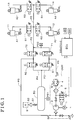
- An outlet valve (a relief valve) 5 serving as a normally-closed magnetic on-off valve is provided at an outlet flow passage.
- An inlet and outlet flow passage P1 is provided with a check valve 4 allowing the flow of air in an outlet direction and preventing air from flowing in an opposite direction.
- An orifice 6 normally communicating with the check valve 4 via a restriction is disposed in parallel to the check valve 4.
- OP corresponds to an outlet port
- BP corresponds to a back pressure introduction port
- AP corresponds to an air inlet port.
- Each of wheel on-off valves 61, 62, 63, 64 serving as a control valve controlling the inlet and outlet of air to each of the air chambers 11, 12, 13, 14 is provided at the inlet and outlet flow passage P2 that is communicatingly connected to each of the air chambers 11, 12, 13, 14.
- the inlet and outlet flow passage P1 that is disposed between a set of the wheel on-off valves 61, 62, 63, 64 and the compressor device CMP is provided with an inlet and outlet on-off valve 71 (i.e., serving as a first inlet and outlet on-off valve) opening and closing the inlet and outlet flow passage P1 .
- the inlet and outlet flow passage P3 that is disposed between the pressure accumulation tank 50 and the outlet port OP of the compressor device CMP is provided with a tank on-off valve 81 (i.e., serving as a first tank on-off valve) opening and closing the inlet and outlet flow passage P3.
- the inlet and outlet flow passage P4 that is disposed between the set of the wheel on-off valves 61, 62, 63, 64 and the pressure accumulation tank 50 is provided with an inlet and outlet on-off valve 72 (i.e., serving as a second inlet and outlet on-off valve) and a tank on-off valve 82 (i.e., serving as a second tank on-off valve).
- a portion between the inlet and outlet on-off valve 72 and the tank on-off valve 82 is connected to the back pressure introduction port BP of the compressor device CMP via a circulation flow passage P5.
- a circulation flow passage P5 According to the embodiment, as shown in Fig.
- the wheel on-off valves 61, 62, 63, 64, the inlet and outlet on-off valves 71, 72 and the tank on-off valves 81, 82 each corresponds to a normally-closed magnetic on-off valve (However, each of the wheel on-off valves 61, 62, 63, 64, the inlet and outlet on-off valves 71, 72 and the tank on-off valves 81, 82 corresponds to a relief valve when they are in a closed position).
- Pressure sensors PS1, PS2 are disposed at the inlet and outlet flow passages P2, P4 (or P3), respectively.
- the pressure sensor PS1 detects a pressure level within the pressure accumulation tank 50.
- the pressure sensor PS2 detects a pressure level within the inlet and outlet flow passage P2.
- the pressure sensors PS1, PS2 send detected pressure signals to the control unit ECU.
- the control unit ECU controls the inlet and outlet on-off valve 72, the tank on-off valve 82, and the wheel on-off valves 61, 62, 63, 64 to be closed.
- the control unit ECU controls the electric motor 1 to be operated while closing the inlet and outlet on-off valve 71. Accordingly, compressed air is supplied from the outlet portion OP to the inlet and outlet flow passage P2 until the vehicle height value reaches the targeted vehicle height value.
- the control unit ECU controls the tank on-off valve 81 and the outlet valve 5 to be opened. Accordingly, the dried air within the pressure accumulation tank 50 is discharged via the orifice 6 and the dryer 3. When the dried air is discharged, the drying agent within the dryer 3 is regenerated. After the regeneration, the control unit ECU controls the outlet valve 5 to be closed. In a case where the control unit ECU controls the electric motor 1 to be operated, air is entered from the air inlet port AP. The compressed air generated by the pump device 2 is supplied from the outlet port OP to the pressure accumulation tank 50 via the tank on-off valve 81 that is open.
- the control unit ECU controls the electric motor 1 to be operated while controlling the tank on-off valve 81 to be closed. Accordingly, the pressure accumulation tank 50 is returned to a high-pressure maintaining state.
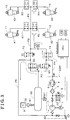
- the exterior compressed air source 9 is connected to the check valve 51 (via the dryer 52 if required).
- the control unit ECU controls the inlet and outlet on-off valves 71, 72, the tank on-off valves 81, 82, and the wheel on-off valves 61, 62, 63, 64 to be opened.
- the compressed air supplied from the exterior compressed air source 9 to the pressure accumulation tank 50 is filled in the air spring devices A1, A2, A3, A4 via the inlet and outlet flow passages P3, P4 and the inlet and outlet flow passage P2 as shown in thin arrows in Fig. 2 .
- the control unit ECU controls the electric motor 1 to be operated while contolling the inlet and outlet on-off valve 72 and the tank on-off valve 81 to be returned to respective normal positions in Fig. 1 .
- the compressed air that has a pressure level equal to or greater than the pressure level of the compressed air supplied from the exterior compressed air source 9 (for example, 1.0 MPa that exceeds the general pressure level of the air chambers 11, 12, 13, 14) is discharged from the compressor device CMP.
- the pressure level of the compressed air supplied from the exterior compressed air source 9 for example, 1.0 MPa that exceeds the general pressure level of the air chambers 11, 12, 13, 14
- the compressed air is filled within the air spring devices A1, A2, A3, A4 via the inlet and outlet flow passage P1, the inlet and outlet on-off valve 71 that is open, the inlet and outlet flow passage P2 and the wheel on-off valves 61, 62, 63, 64 that are open.
- the compressed air the pressure level of 0.5 MPa
- the compressed air may be effectively and promptly boosted (until the pressure level comes to be 1.0 MPa).
- the exterior compressed air source 9 (and the dryer 52) is removed from the pressure accumulation tank 50, and comes to be a state shown in Fig. 4 .
- the air within the air spring devices A1, A2, A3, A4 is greater than a predetermined pressure level (or the vehicle height value is greater than a predetermined value).
- the control unit ECU controls the inlet and outlet on-off valves 71, 72, the tank on-off valves 81, 82, and the wheel on-off valves 61, 62, 63, 64 to be opened, similarly to the inlet and outlet on-off valves 71, 72, the tank on-off valves 81, 82, and the wheel on-off valves 61, 62, 63, 64 shown in Fig. 2 .
- the control unit ECU controls the inlet and outlet on-off valves 71, 72, the tank on-off valves 81, 82, and the wheel on-off valves 61, 62, 63, 64 to be opened, similarly to the inlet and outlet on-off valves 71, 72, the tank on-off valves 81, 82, and the wheel on-off valves 61, 62, 63, 64 shown in Fig. 2 .
- the pressure levels within the air spring devices A1, A2, A3, A4 are greater than the pressure level within the pressure accumulation
- the compressed air filled in the air spring devices A1, A2, A3, A4 is supplied to the pressure accumulation tank 50 via the inlet and outlet flow passage P2 and inlet and outlet flow passages P3, P4.
- the control unit ECU controls the tank on-off valve 81 and the inlet and outlet on-off valve 72 to be opened, and controls the tank on-off valve 82 and the inlet and outlet on-off valve V71 to be closed.
- the pressure level control operated only by the control unit ECU may be smoothly shifted.
- the high-pressure compressed air filled in the air spring devices A1, A2, A3, A4 is supplied to the pressure accumulation tank 50.
- the high-pressure compressed air filled in the air spring devices A1, A2, A3, A4 is introduced to the compressor device CMP. Accordingly, the outlet efficiency of the compressor device CMP may be further favorable.
- the compressed air within the air spring devices A1, A2, A3, A4 is sent to the pressure accumulation tank 50 until a predetermined vehicle height is established.
- the control unit ECU controls the tank on-off valve 81 and the outlet valve 5 to be closed. Accordingly, the compressed air within the pressure accumulation tank 50 is discharged to an outside air via the inlet and outlet flow passage P3, the tank on-off valve 81, the inlet and outlet flow passage P1, the orifice 6, the dryer 3, and the outlet valve 5.
- the control unit ECU controls the electric motor 1 to be operated while controlling the tank on-off valve 81 to be opened.
- the air flowing from the air inlet port AP is compressed by the pump device 2.
- the compressed air is discharged from the outlet port OP via the dryer 3 and the check valve 4, and is supplied to the pressure accumulation tank 50 via the open tank on-off valve 81.
- the control unit ECU controls the tank on-off valve 81 to be closed and controls the electric motor 1 to stop operating.
- the exterior compressed air source 9 supplies the compressed air to the pressure accumulation tank 50 by using the pressure source having a pressure level lower than the pressure level of air (for example, the compressed air within a general factory) that is to be supplied to the air spring devices A1, A2, A3, A4. Because the compressed air is boosted by the compressor device CMP and is filled in the air chambers 11, 12, 13, 14 of the air spring devices A1, A2, A3, A4, each of the air spring devices A1, A2, A3, A4 works as a pressure accumulating chamber and the high-pressure compressed air that is desired by the pressure accumulation tank 50 may be secured. Because the air introduced to the compressor device CMP corresponds to the compressed air supplied from the exterior compressed air source 9 to the pressure accumulation tank 50, the compressed air may be boosted efficiently and promptly.
- the pressure source having a pressure level lower than the pressure level of air (for example, the compressed air within a general factory) that is to be supplied to the air spring devices A1, A2, A3, A4. Because the compressed air is boosted by the compressor device CMP and is filled in the air
- the high-pressure compressed air filled in the air spring devices A1, A2, A3, A4 is supplied to the pressure accumulation tank 50.
- the compressed air is required to be further boosted by the compressor device CMP
- the high-pressure compressed air filled in the air spring devices A1, A2, A3, A4 is introduced to the compressor device CMP. Accordingly, the outlet efficiency of the compressor device CMP may be favorable. In this case, because the drying agent does not have to be regenerated by the dryer 3, the compressed air may be further efficiently and promptly boosted.
Landscapes
- Engineering & Computer Science (AREA)
- Mechanical Engineering (AREA)
- Vehicle Body Suspensions (AREA)
Claims (3)
- Dispositif de suspension pneumatique, comprenant :un dispositif à amortissement pneumatique (A1, A2, A3, A4) configuré pour être monté sur une roue d'un véhicule, le dispositif à amortissement pneumatique (A1, A2, A3, A4) comprenant une chambre à air (11, 12, 13, 14) ;un dispositif compresseur (CMP) comprenant un orifice de sortie (OP) et un orifice d'introduction de contre-pression (BP), le dispositif compresseur (CMP) comprimant l'air et déchargeant l'air comprimé depuis l'orifice de sortie (OP) ;un réservoir d'accumulation de pression (50) accumulant de l'air ;une première soupape d'ouverture-fermeture d'entrée et de sortie (71) étant ménagée au niveau d'un premier passage d'écoulement d'entrée et de sortie (P1) qui est disposé entre une soupape de commande (61, 62, 63, 64) et le dispositif compresseur (CMP);la soupape de commande (61, 62, 63, 64) étant ménagée au niveau d'un deuxième passage d'écoulement d'entrée et de sortie (P2) ;une première soupape d'ouverture-fermeture de réservoir (81) étant ménagée au niveau d'un troisième passage d'écoulement d'entrée et de sortie (P3) qui est disposé entre le réservoir d'accumulation de pression (50) et l'orifice de sortie (OP) du dispositif compresseur (CMP) ;une seconde soupape d'ouverture-fermeture d'entrée et de sortie (72) étant ménagée sur un quatrième passage d'écoulement d'entrée et de sortie (P4) qui est disposé entre la soupape de commande (61, 62, 63, 64) et le réservoir d'accumulation de pression (50) ;une seconde soupape d'ouverture-fermeture de réservoir (82) étant ménagée au niveau du quatrième passage d'écoulement d'entrée et de sortie (P4) qui est disposé entre la soupape de commande (61, 62, 63, 64) et le réservoir d'accumulation de pression (50) ;un passage d'écoulement de circulation (P5) reliant par communication la seconde soupape d'ouverture-fermeture d'entrée et de sortie (72) et la seconde soupape d'ouverture-fermeture de réservoir (82) à l'orifice d'introduction de pression arrière (BP) du dispositif compresseur (CMP) ;une unité de commande (ECU) commandant une ouverture et une fermeture de la soupape de commande (61, 62, 63, 64), des première et seconde soupapes d'ouverture-fermeture d'entrée et de sortie (71, 72) et des première et seconde soupapes d'ouverture-fermeture de réservoir (81, 82) ; etune source d'air comprimé extérieure (9) pouvant être retirée du réservoir d'accumulation de pression (50), la source d'air comprimé extérieure (9) fournissant l'air comprimé à l'accumulateur de pression (50), la source d'air comprimé extérieure (9) fournissant l'air comprimé ayant un niveau de pression inférieur à un niveau de pression d'air devant être fourni au dispositif à amortissement pneumatique (A1, A2, A3, A4) ; dans lequelles premier et deuxième passages d'entrée et de sortie (P1, P2) relient par communication l'orifice de sortie (OP) du dispositif compresseur (CMP) à la chambre à air (11, 12, 13, 14) ;la source d'air comprimé extérieure (9) est montée sur le réservoir d'accumulation de pression (50) pour fournir l'air comprimé ; etl'unité de commande (ECU) commande le compresseur (CMP) pour augmenter la pression d'air dans le réservoir d'accumulation de pression (50) pour remplir le dispositif à amortissement pneumatique (A1, A2, A3, A4) avec de l'air comprimé ;caractérisé en ce quele réservoir d'accumulation de pression (50) est muni d'un clapet anti-retour (51) et dans le cas où il est souhaité que l'air comprimé soit amené au réservoir d'accumulation de pression (50) par la source d'air comprimé extérieure (9), la source d'air comprimé extérieure (9) est reliée au clapet anti-retour (51) ; et en ce quel'unité de commande (ECU) commande les première et seconde soupapes d'ouverture-fermeture d'entrée et de sortie (71, 72), les première et seconde soupapes d'ouverture-fermeture de réservoir (81, 82) et la soupape de commande (61, 62, 63, 64) pour au moins fournir de l'air comprimé dans le dispositif à amortissement pneumatique (A1, A2, A3, A4) au réservoir d'accumulation de pression (50) lorsqu'un niveau de pression d'air dans le dispositif à amortissement pneumatique (A1, A2, A3, A4) devient supérieur à un niveau de pression prédéterminé, ou lorsque la valeur de la hauteur du véhicule devient supérieure à une valeur prédéterminée.
- Dispositif de suspension pneumatique selon la revendication 1, comprenant en outre :
un dispositif de séchage (3) disposé entre la source d'air comprimé extérieure (9) et le réservoir d'accumulation de pression (50), le dispositif de séchage (3) éliminant l'humidité de l'air comprimé. - Dispositif de suspension pneumatique selon la revendication 1 ou 2, dans lequel
la soupape de commande (61, 62, 63, 64) est ménagée au niveau du deuxième passage d'écoulement d'entrée et de sortie (P2) ;
les premier et deuxième passages d'entrée et de sortie (P1, P2) relient en communication la chambre à air (11, 12, 13, 14) du dispositif à amortissement pneumatique (A1, A2, A3, A4) qui est monté sur la roue à l'orifice de sortie (OP) du compresseur (CMP) ; et
la soupape de commande (61, 62, 63, 64) sert de soupape d'ouverture-fermeture de roue ouvrant et fermant le passage d'écoulement d'entrée et de sortie (P2).
Applications Claiming Priority (1)
| Application Number | Priority Date | Filing Date | Title |
|---|---|---|---|
| JP2015250506A JP6701718B2 (ja) | 2015-12-22 | 2015-12-22 | エアサスペンション装置 |
Publications (2)
| Publication Number | Publication Date |
|---|---|
| EP3184331A1 EP3184331A1 (fr) | 2017-06-28 |
| EP3184331B1 true EP3184331B1 (fr) | 2018-08-29 |
Family
ID=57389301
Family Applications (1)
| Application Number | Title | Priority Date | Filing Date |
|---|---|---|---|
| EP16199953.7A Active EP3184331B1 (fr) | 2015-12-22 | 2016-11-22 | Dispositif de suspension pneumatique |
Country Status (3)
| Country | Link |
|---|---|
| EP (1) | EP3184331B1 (fr) |
| JP (1) | JP6701718B2 (fr) |
| CN (1) | CN107009838A (fr) |
Families Citing this family (7)
| Publication number | Priority date | Publication date | Assignee | Title |
|---|---|---|---|---|
| US10967697B2 (en) * | 2016-03-29 | 2021-04-06 | Hitachi Automotive Systems, Ltd. | Air suspension system |
| US11034205B2 (en) | 2017-10-18 | 2021-06-15 | Beijingwest Industries Co., Ltd. | Concurrent leveling system for a vehicle |
| CN109466270B (zh) * | 2017-10-18 | 2020-07-24 | 北京京西重工有限公司 | 用于车辆的并行调平系统 |
| DE102018213998B4 (de) * | 2018-08-20 | 2020-12-10 | Continental Teves Ag & Co. Ohg | Verfahren zur Ansteuerung eines Elektromagnetventils und Druckluftanlage mit einem Elektromagnetventil |
| US10900538B2 (en) | 2018-10-29 | 2021-01-26 | Continental Automotive Systems, Inc. | Pressure relief for air springs |
| JP2020172159A (ja) * | 2019-04-10 | 2020-10-22 | Kyb株式会社 | 車両 |
| DE102021201458B3 (de) | 2020-12-08 | 2021-10-28 | Continental Teves Ag & Co. Ohg | Verfahren zum Betreiben einer Luftfederungsanlage mit einer Trocknerregenerationsfunktion |
Citations (2)
| Publication number | Priority date | Publication date | Assignee | Title |
|---|---|---|---|---|
| DE102004028479A1 (de) * | 2003-06-13 | 2005-01-05 | Luk Fahrzeug-Hydraulik Gmbh & Co Kg | Niveauregelsystem |
| DE102008011543A1 (de) * | 2008-02-28 | 2009-09-03 | Continental Aktiengesellschaft | Verfahren zum Ausgleich eines Leckageverlustes in einer Niveauregelanlage |
Family Cites Families (7)
| Publication number | Priority date | Publication date | Assignee | Title |
|---|---|---|---|---|
| DE102005030726A1 (de) * | 2005-07-01 | 2007-01-04 | Continental Aktiengesellschaft | Luftfederungsanlage für ein Kraftfahrzeug |
| DE102009025970A1 (de) * | 2009-06-15 | 2010-12-16 | Continental Aktiengesellschaft | Verfahren zur Funktionskontrolle einer Luftfederungsanlage |
| DE102010041609A1 (de) * | 2009-09-29 | 2011-03-31 | Continental Teves Ag & Co. Ohg | Verfahren zum Befüllen eines elektronisch regelbaren Luftfedersystems für Kraftfahrzeuge und Vorrichtung zur Durchführung des Verfahrens |
| US8840119B2 (en) * | 2012-06-11 | 2014-09-23 | F. Brent Davis | Modular dynamically adjustable suspension system for trailers |
| DE102012222982A1 (de) * | 2012-12-12 | 2014-06-12 | Continental Teves Ag & Co. Ohg | Verfahren zum Befüllen der Luftfedern eines Fahrzeuges undzugehöriger Druckspeicher |
| JP6264536B2 (ja) | 2013-11-18 | 2018-01-24 | アイシン精機株式会社 | エアコンプレッサ装置 |
| JP6167878B2 (ja) * | 2013-11-29 | 2017-07-26 | アイシン精機株式会社 | 車高調整装置 |
-
2015
- 2015-12-22 JP JP2015250506A patent/JP6701718B2/ja active Active
-
2016
- 2016-11-22 EP EP16199953.7A patent/EP3184331B1/fr active Active
- 2016-12-21 CN CN201611191632.6A patent/CN107009838A/zh active Pending
Patent Citations (2)
| Publication number | Priority date | Publication date | Assignee | Title |
|---|---|---|---|---|
| DE102004028479A1 (de) * | 2003-06-13 | 2005-01-05 | Luk Fahrzeug-Hydraulik Gmbh & Co Kg | Niveauregelsystem |
| DE102008011543A1 (de) * | 2008-02-28 | 2009-09-03 | Continental Aktiengesellschaft | Verfahren zum Ausgleich eines Leckageverlustes in einer Niveauregelanlage |
Also Published As
| Publication number | Publication date |
|---|---|
| CN107009838A (zh) | 2017-08-04 |
| JP2017114239A (ja) | 2017-06-29 |
| EP3184331A1 (fr) | 2017-06-28 |
| JP6701718B2 (ja) | 2020-05-27 |
Similar Documents
| Publication | Publication Date | Title |
|---|---|---|
| EP3184331B1 (fr) | Dispositif de suspension pneumatique | |
| KR101993497B1 (ko) | 압력 매체 공급 시스템, 공압 시스템, 및 압력 매체 공급 시스템을 작동하는 방법 | |
| CN104010846B (zh) | 机动车的空气悬架系统和用于对其进行控制的方法 | |
| CN104039570B (zh) | 机动车的空气悬架系统和用于对其进行控制的方法 | |
| CN106470855B (zh) | 压缩空气供应设备以及其控制方法和气动的系统 | |
| CN104080631B (zh) | 压缩空气供给设备、气动系统和用于运行压缩空气供给设备或气动系统的方法 | |
| CN109153307B (zh) | 空气悬架装置的干燥器再生方法 | |
| US20130276899A1 (en) | Compressed Air Supply Installation, Pneumatic System and Method for Operating a Pneumatic Installation | |
| CN107614296B (zh) | 空气悬架系统 | |
| CN103687768B (zh) | 压缩空气处理设备和用于运行压缩空气处理设备的方法 | |
| US8403427B2 (en) | Vehicle air supply system | |
| US20190100070A1 (en) | Air suspension apparatus | |
| CN109070680B (zh) | 车辆高度控制系统 | |
| US20210394577A1 (en) | Air suspension system | |
| US20170341480A1 (en) | Air suspension system | |
| US9555672B2 (en) | Pressure control device for a tire inflating system with a rotary feedthrough, and tire pressure changing method | |
| CN105307915B (zh) | 液压制动系统、放气装置、放气方法 | |
| CN115946491A (zh) | 用于车辆高度调节的供气系统和供气方法 | |
| JP7126550B2 (ja) | サスペンション装置 | |
| WO2003084792A1 (fr) | Procede et systeme de sechage a module reservoir secheur a flux continu | |
| JP2020066291A (ja) | サスペンションシステム | |
| JP4710737B2 (ja) | 車両用ブレーキ装置 | |
| CN223686282U (zh) | 车用气动系统和车辆 | |
| CN119526964A (zh) | 一种气体供给系统及具有该气体供给系统的空气弹簧系统 | |
| CN120712189A (zh) | 用于运行压缩空气设备的方法 |
Legal Events
| Date | Code | Title | Description |
|---|---|---|---|
| PUAI | Public reference made under article 153(3) epc to a published international application that has entered the european phase |
Free format text: ORIGINAL CODE: 0009012 |
|
| AK | Designated contracting states |
Kind code of ref document: A1 Designated state(s): AL AT BE BG CH CY CZ DE DK EE ES FI FR GB GR HR HU IE IS IT LI LT LU LV MC MK MT NL NO PL PT RO RS SE SI SK SM TR |
|
| AX | Request for extension of the european patent |
Extension state: BA ME |
|
| 17P | Request for examination filed |
Effective date: 20170816 |
|
| RBV | Designated contracting states (corrected) |
Designated state(s): AL AT BE BG CH CY CZ DE DK EE ES FI FR GB GR HR HU IE IS IT LI LT LU LV MC MK MT NL NO PL PT RO RS SE SI SK SM TR |
|
| GRAP | Despatch of communication of intention to grant a patent |
Free format text: ORIGINAL CODE: EPIDOSNIGR1 |
|
| INTG | Intention to grant announced |
Effective date: 20180305 |
|
| RIN1 | Information on inventor provided before grant (corrected) |
Inventor name: OISHI, MASAAKI |
|
| GRAS | Grant fee paid |
Free format text: ORIGINAL CODE: EPIDOSNIGR3 |
|
| GRAA | (expected) grant |
Free format text: ORIGINAL CODE: 0009210 |
|
| RIN1 | Information on inventor provided before grant (corrected) |
Inventor name: OISHI, MASAAKI |
|
| AK | Designated contracting states |
Kind code of ref document: B1 Designated state(s): AL AT BE BG CH CY CZ DE DK EE ES FI FR GB GR HR HU IE IS IT LI LT LU LV MC MK MT NL NO PL PT RO RS SE SI SK SM TR |
|
| REG | Reference to a national code |
Ref country code: GB Ref legal event code: FG4D |
|
| REG | Reference to a national code |
Ref country code: CH Ref legal event code: EP |
|
| REG | Reference to a national code |
Ref country code: AT Ref legal event code: REF Ref document number: 1034690 Country of ref document: AT Kind code of ref document: T Effective date: 20180915 |
|
| REG | Reference to a national code |
Ref country code: IE Ref legal event code: FG4D |
|
| REG | Reference to a national code |
Ref country code: DE Ref legal event code: R096 Ref document number: 602016005154 Country of ref document: DE |
|
| REG | Reference to a national code |
Ref country code: NL Ref legal event code: MP Effective date: 20180829 |
|
| REG | Reference to a national code |
Ref country code: LT Ref legal event code: MG4D |
|
| PG25 | Lapsed in a contracting state [announced via postgrant information from national office to epo] |
Ref country code: NO Free format text: LAPSE BECAUSE OF FAILURE TO SUBMIT A TRANSLATION OF THE DESCRIPTION OR TO PAY THE FEE WITHIN THE PRESCRIBED TIME-LIMIT Effective date: 20181129 Ref country code: FI Free format text: LAPSE BECAUSE OF FAILURE TO SUBMIT A TRANSLATION OF THE DESCRIPTION OR TO PAY THE FEE WITHIN THE PRESCRIBED TIME-LIMIT Effective date: 20180829 Ref country code: RS Free format text: LAPSE BECAUSE OF FAILURE TO SUBMIT A TRANSLATION OF THE DESCRIPTION OR TO PAY THE FEE WITHIN THE PRESCRIBED TIME-LIMIT Effective date: 20180829 Ref country code: IS Free format text: LAPSE BECAUSE OF FAILURE TO SUBMIT A TRANSLATION OF THE DESCRIPTION OR TO PAY THE FEE WITHIN THE PRESCRIBED TIME-LIMIT Effective date: 20181229 Ref country code: LT Free format text: LAPSE BECAUSE OF FAILURE TO SUBMIT A TRANSLATION OF THE DESCRIPTION OR TO PAY THE FEE WITHIN THE PRESCRIBED TIME-LIMIT Effective date: 20180829 Ref country code: NL Free format text: LAPSE BECAUSE OF FAILURE TO SUBMIT A TRANSLATION OF THE DESCRIPTION OR TO PAY THE FEE WITHIN THE PRESCRIBED TIME-LIMIT Effective date: 20180829 Ref country code: BG Free format text: LAPSE BECAUSE OF FAILURE TO SUBMIT A TRANSLATION OF THE DESCRIPTION OR TO PAY THE FEE WITHIN THE PRESCRIBED TIME-LIMIT Effective date: 20181129 Ref country code: SE Free format text: LAPSE BECAUSE OF FAILURE TO SUBMIT A TRANSLATION OF THE DESCRIPTION OR TO PAY THE FEE WITHIN THE PRESCRIBED TIME-LIMIT Effective date: 20180829 Ref country code: GR Free format text: LAPSE BECAUSE OF FAILURE TO SUBMIT A TRANSLATION OF THE DESCRIPTION OR TO PAY THE FEE WITHIN THE PRESCRIBED TIME-LIMIT Effective date: 20181130 |
|
| REG | Reference to a national code |
Ref country code: AT Ref legal event code: MK05 Ref document number: 1034690 Country of ref document: AT Kind code of ref document: T Effective date: 20180829 |
|
| PG25 | Lapsed in a contracting state [announced via postgrant information from national office to epo] |
Ref country code: LV Free format text: LAPSE BECAUSE OF FAILURE TO SUBMIT A TRANSLATION OF THE DESCRIPTION OR TO PAY THE FEE WITHIN THE PRESCRIBED TIME-LIMIT Effective date: 20180829 Ref country code: AL Free format text: LAPSE BECAUSE OF FAILURE TO SUBMIT A TRANSLATION OF THE DESCRIPTION OR TO PAY THE FEE WITHIN THE PRESCRIBED TIME-LIMIT Effective date: 20180829 Ref country code: HR Free format text: LAPSE BECAUSE OF FAILURE TO SUBMIT A TRANSLATION OF THE DESCRIPTION OR TO PAY THE FEE WITHIN THE PRESCRIBED TIME-LIMIT Effective date: 20180829 |
|
| PG25 | Lapsed in a contracting state [announced via postgrant information from national office to epo] |
Ref country code: AT Free format text: LAPSE BECAUSE OF FAILURE TO SUBMIT A TRANSLATION OF THE DESCRIPTION OR TO PAY THE FEE WITHIN THE PRESCRIBED TIME-LIMIT Effective date: 20180829 Ref country code: ES Free format text: LAPSE BECAUSE OF FAILURE TO SUBMIT A TRANSLATION OF THE DESCRIPTION OR TO PAY THE FEE WITHIN THE PRESCRIBED TIME-LIMIT Effective date: 20180829 Ref country code: PL Free format text: LAPSE BECAUSE OF FAILURE TO SUBMIT A TRANSLATION OF THE DESCRIPTION OR TO PAY THE FEE WITHIN THE PRESCRIBED TIME-LIMIT Effective date: 20180829 Ref country code: RO Free format text: LAPSE BECAUSE OF FAILURE TO SUBMIT A TRANSLATION OF THE DESCRIPTION OR TO PAY THE FEE WITHIN THE PRESCRIBED TIME-LIMIT Effective date: 20180829 Ref country code: CZ Free format text: LAPSE BECAUSE OF FAILURE TO SUBMIT A TRANSLATION OF THE DESCRIPTION OR TO PAY THE FEE WITHIN THE PRESCRIBED TIME-LIMIT Effective date: 20180829 Ref country code: EE Free format text: LAPSE BECAUSE OF FAILURE TO SUBMIT A TRANSLATION OF THE DESCRIPTION OR TO PAY THE FEE WITHIN THE PRESCRIBED TIME-LIMIT Effective date: 20180829 Ref country code: IT Free format text: LAPSE BECAUSE OF FAILURE TO SUBMIT A TRANSLATION OF THE DESCRIPTION OR TO PAY THE FEE WITHIN THE PRESCRIBED TIME-LIMIT Effective date: 20180829 |
|
| PG25 | Lapsed in a contracting state [announced via postgrant information from national office to epo] |
Ref country code: SK Free format text: LAPSE BECAUSE OF FAILURE TO SUBMIT A TRANSLATION OF THE DESCRIPTION OR TO PAY THE FEE WITHIN THE PRESCRIBED TIME-LIMIT Effective date: 20180829 Ref country code: DK Free format text: LAPSE BECAUSE OF FAILURE TO SUBMIT A TRANSLATION OF THE DESCRIPTION OR TO PAY THE FEE WITHIN THE PRESCRIBED TIME-LIMIT Effective date: 20180829 Ref country code: SM Free format text: LAPSE BECAUSE OF FAILURE TO SUBMIT A TRANSLATION OF THE DESCRIPTION OR TO PAY THE FEE WITHIN THE PRESCRIBED TIME-LIMIT Effective date: 20180829 |
|
| REG | Reference to a national code |
Ref country code: DE Ref legal event code: R097 Ref document number: 602016005154 Country of ref document: DE |
|
| PLBE | No opposition filed within time limit |
Free format text: ORIGINAL CODE: 0009261 |
|
| STAA | Information on the status of an ep patent application or granted ep patent |
Free format text: STATUS: NO OPPOSITION FILED WITHIN TIME LIMIT |
|
| PG25 | Lapsed in a contracting state [announced via postgrant information from national office to epo] |
Ref country code: LU Free format text: LAPSE BECAUSE OF NON-PAYMENT OF DUE FEES Effective date: 20181122 Ref country code: MC Free format text: LAPSE BECAUSE OF FAILURE TO SUBMIT A TRANSLATION OF THE DESCRIPTION OR TO PAY THE FEE WITHIN THE PRESCRIBED TIME-LIMIT Effective date: 20180829 |
|
| 26N | No opposition filed |
Effective date: 20190531 |
|
| REG | Reference to a national code |
Ref country code: BE Ref legal event code: MM Effective date: 20181130 |
|
| REG | Reference to a national code |
Ref country code: IE Ref legal event code: MM4A |
|
| PG25 | Lapsed in a contracting state [announced via postgrant information from national office to epo] |
Ref country code: SI Free format text: LAPSE BECAUSE OF FAILURE TO SUBMIT A TRANSLATION OF THE DESCRIPTION OR TO PAY THE FEE WITHIN THE PRESCRIBED TIME-LIMIT Effective date: 20180829 |
|
| PG25 | Lapsed in a contracting state [announced via postgrant information from national office to epo] |
Ref country code: IE Free format text: LAPSE BECAUSE OF NON-PAYMENT OF DUE FEES Effective date: 20181122 Ref country code: FR Free format text: LAPSE BECAUSE OF NON-PAYMENT OF DUE FEES Effective date: 20181130 |
|
| PG25 | Lapsed in a contracting state [announced via postgrant information from national office to epo] |
Ref country code: BE Free format text: LAPSE BECAUSE OF NON-PAYMENT OF DUE FEES Effective date: 20181130 |
|
| PG25 | Lapsed in a contracting state [announced via postgrant information from national office to epo] |
Ref country code: MT Free format text: LAPSE BECAUSE OF NON-PAYMENT OF DUE FEES Effective date: 20181122 |
|
| PG25 | Lapsed in a contracting state [announced via postgrant information from national office to epo] |
Ref country code: TR Free format text: LAPSE BECAUSE OF FAILURE TO SUBMIT A TRANSLATION OF THE DESCRIPTION OR TO PAY THE FEE WITHIN THE PRESCRIBED TIME-LIMIT Effective date: 20180829 |
|
| PG25 | Lapsed in a contracting state [announced via postgrant information from national office to epo] |
Ref country code: PT Free format text: LAPSE BECAUSE OF FAILURE TO SUBMIT A TRANSLATION OF THE DESCRIPTION OR TO PAY THE FEE WITHIN THE PRESCRIBED TIME-LIMIT Effective date: 20180829 |
|
| PG25 | Lapsed in a contracting state [announced via postgrant information from national office to epo] |
Ref country code: MK Free format text: LAPSE BECAUSE OF NON-PAYMENT OF DUE FEES Effective date: 20180829 Ref country code: CY Free format text: LAPSE BECAUSE OF FAILURE TO SUBMIT A TRANSLATION OF THE DESCRIPTION OR TO PAY THE FEE WITHIN THE PRESCRIBED TIME-LIMIT Effective date: 20180829 Ref country code: HU Free format text: LAPSE BECAUSE OF FAILURE TO SUBMIT A TRANSLATION OF THE DESCRIPTION OR TO PAY THE FEE WITHIN THE PRESCRIBED TIME-LIMIT; INVALID AB INITIO Effective date: 20161122 |
|
| REG | Reference to a national code |
Ref country code: CH Ref legal event code: PL |
|
| PG25 | Lapsed in a contracting state [announced via postgrant information from national office to epo] |
Ref country code: LI Free format text: LAPSE BECAUSE OF NON-PAYMENT OF DUE FEES Effective date: 20191130 Ref country code: CH Free format text: LAPSE BECAUSE OF NON-PAYMENT OF DUE FEES Effective date: 20191130 |
|
| GBPC | Gb: european patent ceased through non-payment of renewal fee |
Effective date: 20201122 |
|
| PG25 | Lapsed in a contracting state [announced via postgrant information from national office to epo] |
Ref country code: GB Free format text: LAPSE BECAUSE OF NON-PAYMENT OF DUE FEES Effective date: 20201122 |
|
| PGFP | Annual fee paid to national office [announced via postgrant information from national office to epo] |
Ref country code: DE Payment date: 20250930 Year of fee payment: 10 |