EP3184351A1 - Systeme d'alimentation en energie pour une vehicule de chantiers miniers et vehicule de chantiers miniers - Google Patents
Systeme d'alimentation en energie pour une vehicule de chantiers miniers et vehicule de chantiers miniers Download PDFInfo
- Publication number
- EP3184351A1 EP3184351A1 EP15201975.8A EP15201975A EP3184351A1 EP 3184351 A1 EP3184351 A1 EP 3184351A1 EP 15201975 A EP15201975 A EP 15201975A EP 3184351 A1 EP3184351 A1 EP 3184351A1
- Authority
- EP
- European Patent Office
- Prior art keywords
- supply system
- power supply
- voltage
- converter
- catenary
- Prior art date
- Legal status (The legal status is an assumption and is not a legal conclusion. Google has not performed a legal analysis and makes no representation as to the accuracy of the status listed.)
- Withdrawn
Links
- 238000005065 mining Methods 0.000 title claims abstract description 16
- 230000008878 coupling Effects 0.000 claims description 25
- 238000010168 coupling process Methods 0.000 claims description 25
- 238000005859 coupling reaction Methods 0.000 claims description 25
- 238000002485 combustion reaction Methods 0.000 claims description 7
- 230000001939 inductive effect Effects 0.000 claims description 4
- 230000001419 dependent effect Effects 0.000 claims description 2
- 239000003990 capacitor Substances 0.000 description 3
- 230000001131 transforming effect Effects 0.000 description 2
- 230000015572 biosynthetic process Effects 0.000 description 1
- 238000004146 energy storage Methods 0.000 description 1
- 230000010354 integration Effects 0.000 description 1
- 238000011084 recovery Methods 0.000 description 1
Images
Classifications
-
- B—PERFORMING OPERATIONS; TRANSPORTING
- B60—VEHICLES IN GENERAL
- B60L—PROPULSION OF ELECTRICALLY-PROPELLED VEHICLES; SUPPLYING ELECTRIC POWER FOR AUXILIARY EQUIPMENT OF ELECTRICALLY-PROPELLED VEHICLES; ELECTRODYNAMIC BRAKE SYSTEMS FOR VEHICLES IN GENERAL; MAGNETIC SUSPENSION OR LEVITATION FOR VEHICLES; MONITORING OPERATING VARIABLES OF ELECTRICALLY-PROPELLED VEHICLES; ELECTRIC SAFETY DEVICES FOR ELECTRICALLY-PROPELLED VEHICLES
- B60L15/00—Methods, circuits, or devices for controlling the traction-motor speed of electrically-propelled vehicles
- B60L15/007—Physical arrangements or structures of drive train converters specially adapted for the propulsion motors of electric vehicles
-
- B—PERFORMING OPERATIONS; TRANSPORTING
- B60—VEHICLES IN GENERAL
- B60L—PROPULSION OF ELECTRICALLY-PROPELLED VEHICLES; SUPPLYING ELECTRIC POWER FOR AUXILIARY EQUIPMENT OF ELECTRICALLY-PROPELLED VEHICLES; ELECTRODYNAMIC BRAKE SYSTEMS FOR VEHICLES IN GENERAL; MAGNETIC SUSPENSION OR LEVITATION FOR VEHICLES; MONITORING OPERATING VARIABLES OF ELECTRICALLY-PROPELLED VEHICLES; ELECTRIC SAFETY DEVICES FOR ELECTRICALLY-PROPELLED VEHICLES
- B60L5/00—Current collectors for power supply lines of electrically-propelled vehicles
- B60L5/36—Current collectors for power supply lines of electrically-propelled vehicles with means for collecting current simultaneously from more than one conductor, e.g. from more than one phase
-
- B—PERFORMING OPERATIONS; TRANSPORTING
- B60—VEHICLES IN GENERAL
- B60L—PROPULSION OF ELECTRICALLY-PROPELLED VEHICLES; SUPPLYING ELECTRIC POWER FOR AUXILIARY EQUIPMENT OF ELECTRICALLY-PROPELLED VEHICLES; ELECTRODYNAMIC BRAKE SYSTEMS FOR VEHICLES IN GENERAL; MAGNETIC SUSPENSION OR LEVITATION FOR VEHICLES; MONITORING OPERATING VARIABLES OF ELECTRICALLY-PROPELLED VEHICLES; ELECTRIC SAFETY DEVICES FOR ELECTRICALLY-PROPELLED VEHICLES
- B60L5/00—Current collectors for power supply lines of electrically-propelled vehicles
- B60L5/38—Current collectors for power supply lines of electrically-propelled vehicles for collecting current from conductor rails
-
- B—PERFORMING OPERATIONS; TRANSPORTING
- B60—VEHICLES IN GENERAL
- B60L—PROPULSION OF ELECTRICALLY-PROPELLED VEHICLES; SUPPLYING ELECTRIC POWER FOR AUXILIARY EQUIPMENT OF ELECTRICALLY-PROPELLED VEHICLES; ELECTRODYNAMIC BRAKE SYSTEMS FOR VEHICLES IN GENERAL; MAGNETIC SUSPENSION OR LEVITATION FOR VEHICLES; MONITORING OPERATING VARIABLES OF ELECTRICALLY-PROPELLED VEHICLES; ELECTRIC SAFETY DEVICES FOR ELECTRICALLY-PROPELLED VEHICLES
- B60L50/00—Electric propulsion with power supplied within the vehicle
- B60L50/10—Electric propulsion with power supplied within the vehicle using propulsion power supplied by engine-driven generators, e.g. generators driven by combustion engines
- B60L50/13—Electric propulsion with power supplied within the vehicle using propulsion power supplied by engine-driven generators, e.g. generators driven by combustion engines using AC generators and AC motors
-
- B—PERFORMING OPERATIONS; TRANSPORTING
- B60—VEHICLES IN GENERAL
- B60L—PROPULSION OF ELECTRICALLY-PROPELLED VEHICLES; SUPPLYING ELECTRIC POWER FOR AUXILIARY EQUIPMENT OF ELECTRICALLY-PROPELLED VEHICLES; ELECTRODYNAMIC BRAKE SYSTEMS FOR VEHICLES IN GENERAL; MAGNETIC SUSPENSION OR LEVITATION FOR VEHICLES; MONITORING OPERATING VARIABLES OF ELECTRICALLY-PROPELLED VEHICLES; ELECTRIC SAFETY DEVICES FOR ELECTRICALLY-PROPELLED VEHICLES
- B60L7/00—Electrodynamic brake systems for vehicles in general
- B60L7/02—Dynamic electric resistor braking
- B60L7/06—Dynamic electric resistor braking for vehicles propelled by AC motors
-
- B—PERFORMING OPERATIONS; TRANSPORTING
- B60—VEHICLES IN GENERAL
- B60L—PROPULSION OF ELECTRICALLY-PROPELLED VEHICLES; SUPPLYING ELECTRIC POWER FOR AUXILIARY EQUIPMENT OF ELECTRICALLY-PROPELLED VEHICLES; ELECTRODYNAMIC BRAKE SYSTEMS FOR VEHICLES IN GENERAL; MAGNETIC SUSPENSION OR LEVITATION FOR VEHICLES; MONITORING OPERATING VARIABLES OF ELECTRICALLY-PROPELLED VEHICLES; ELECTRIC SAFETY DEVICES FOR ELECTRICALLY-PROPELLED VEHICLES
- B60L7/00—Electrodynamic brake systems for vehicles in general
- B60L7/10—Dynamic electric regenerative braking
- B60L7/14—Dynamic electric regenerative braking for vehicles propelled by AC motors
-
- B—PERFORMING OPERATIONS; TRANSPORTING
- B60—VEHICLES IN GENERAL
- B60L—PROPULSION OF ELECTRICALLY-PROPELLED VEHICLES; SUPPLYING ELECTRIC POWER FOR AUXILIARY EQUIPMENT OF ELECTRICALLY-PROPELLED VEHICLES; ELECTRODYNAMIC BRAKE SYSTEMS FOR VEHICLES IN GENERAL; MAGNETIC SUSPENSION OR LEVITATION FOR VEHICLES; MONITORING OPERATING VARIABLES OF ELECTRICALLY-PROPELLED VEHICLES; ELECTRIC SAFETY DEVICES FOR ELECTRICALLY-PROPELLED VEHICLES
- B60L9/00—Electric propulsion with power supply external to the vehicle
- B60L9/16—Electric propulsion with power supply external to the vehicle using AC induction motors
- B60L9/24—Electric propulsion with power supply external to the vehicle using AC induction motors fed from AC supply lines
- B60L9/28—Electric propulsion with power supply external to the vehicle using AC induction motors fed from AC supply lines polyphase motors
-
- E—FIXED CONSTRUCTIONS
- E21—EARTH OR ROCK DRILLING; MINING
- E21F—SAFETY DEVICES, TRANSPORT, FILLING-UP, RESCUE, VENTILATION, OR DRAINING IN OR OF MINES OR TUNNELS
- E21F17/00—Methods or devices for use in mines or tunnels, not covered elsewhere
- E21F17/04—Distributing means for power supply in mines
- E21F17/06—Distributing electric power; Cable networks; Conduits for cables
-
- B—PERFORMING OPERATIONS; TRANSPORTING
- B60—VEHICLES IN GENERAL
- B60L—PROPULSION OF ELECTRICALLY-PROPELLED VEHICLES; SUPPLYING ELECTRIC POWER FOR AUXILIARY EQUIPMENT OF ELECTRICALLY-PROPELLED VEHICLES; ELECTRODYNAMIC BRAKE SYSTEMS FOR VEHICLES IN GENERAL; MAGNETIC SUSPENSION OR LEVITATION FOR VEHICLES; MONITORING OPERATING VARIABLES OF ELECTRICALLY-PROPELLED VEHICLES; ELECTRIC SAFETY DEVICES FOR ELECTRICALLY-PROPELLED VEHICLES
- B60L2200/00—Type of vehicles
- B60L2200/36—Vehicles designed to transport cargo, e.g. trucks
-
- B—PERFORMING OPERATIONS; TRANSPORTING
- B60—VEHICLES IN GENERAL
- B60L—PROPULSION OF ELECTRICALLY-PROPELLED VEHICLES; SUPPLYING ELECTRIC POWER FOR AUXILIARY EQUIPMENT OF ELECTRICALLY-PROPELLED VEHICLES; ELECTRODYNAMIC BRAKE SYSTEMS FOR VEHICLES IN GENERAL; MAGNETIC SUSPENSION OR LEVITATION FOR VEHICLES; MONITORING OPERATING VARIABLES OF ELECTRICALLY-PROPELLED VEHICLES; ELECTRIC SAFETY DEVICES FOR ELECTRICALLY-PROPELLED VEHICLES
- B60L2200/00—Type of vehicles
- B60L2200/40—Working vehicles
- B60L2200/44—Industrial trucks or floor conveyors
-
- B—PERFORMING OPERATIONS; TRANSPORTING
- B60—VEHICLES IN GENERAL
- B60L—PROPULSION OF ELECTRICALLY-PROPELLED VEHICLES; SUPPLYING ELECTRIC POWER FOR AUXILIARY EQUIPMENT OF ELECTRICALLY-PROPELLED VEHICLES; ELECTRODYNAMIC BRAKE SYSTEMS FOR VEHICLES IN GENERAL; MAGNETIC SUSPENSION OR LEVITATION FOR VEHICLES; MONITORING OPERATING VARIABLES OF ELECTRICALLY-PROPELLED VEHICLES; ELECTRIC SAFETY DEVICES FOR ELECTRICALLY-PROPELLED VEHICLES
- B60L2210/00—Converter types
- B60L2210/20—AC to AC converters
-
- Y—GENERAL TAGGING OF NEW TECHNOLOGICAL DEVELOPMENTS; GENERAL TAGGING OF CROSS-SECTIONAL TECHNOLOGIES SPANNING OVER SEVERAL SECTIONS OF THE IPC; TECHNICAL SUBJECTS COVERED BY FORMER USPC CROSS-REFERENCE ART COLLECTIONS [XRACs] AND DIGESTS
- Y02—TECHNOLOGIES OR APPLICATIONS FOR MITIGATION OR ADAPTATION AGAINST CLIMATE CHANGE
- Y02P—CLIMATE CHANGE MITIGATION TECHNOLOGIES IN THE PRODUCTION OR PROCESSING OF GOODS
- Y02P90/00—Enabling technologies with a potential contribution to greenhouse gas [GHG] emissions mitigation
- Y02P90/60—Electric or hybrid propulsion means for production processes
-
- Y—GENERAL TAGGING OF NEW TECHNOLOGICAL DEVELOPMENTS; GENERAL TAGGING OF CROSS-SECTIONAL TECHNOLOGIES SPANNING OVER SEVERAL SECTIONS OF THE IPC; TECHNICAL SUBJECTS COVERED BY FORMER USPC CROSS-REFERENCE ART COLLECTIONS [XRACs] AND DIGESTS
- Y02—TECHNOLOGIES OR APPLICATIONS FOR MITIGATION OR ADAPTATION AGAINST CLIMATE CHANGE
- Y02T—CLIMATE CHANGE MITIGATION TECHNOLOGIES RELATED TO TRANSPORTATION
- Y02T10/00—Road transport of goods or passengers
- Y02T10/60—Other road transportation technologies with climate change mitigation effect
- Y02T10/64—Electric machine technologies in electromobility
-
- Y—GENERAL TAGGING OF NEW TECHNOLOGICAL DEVELOPMENTS; GENERAL TAGGING OF CROSS-SECTIONAL TECHNOLOGIES SPANNING OVER SEVERAL SECTIONS OF THE IPC; TECHNICAL SUBJECTS COVERED BY FORMER USPC CROSS-REFERENCE ART COLLECTIONS [XRACs] AND DIGESTS
- Y02—TECHNOLOGIES OR APPLICATIONS FOR MITIGATION OR ADAPTATION AGAINST CLIMATE CHANGE
- Y02T—CLIMATE CHANGE MITIGATION TECHNOLOGIES RELATED TO TRANSPORTATION
- Y02T10/00—Road transport of goods or passengers
- Y02T10/60—Other road transportation technologies with climate change mitigation effect
- Y02T10/7072—Electromobility specific charging systems or methods for batteries, ultracapacitors, supercapacitors or double-layer capacitors
-
- Y—GENERAL TAGGING OF NEW TECHNOLOGICAL DEVELOPMENTS; GENERAL TAGGING OF CROSS-SECTIONAL TECHNOLOGIES SPANNING OVER SEVERAL SECTIONS OF THE IPC; TECHNICAL SUBJECTS COVERED BY FORMER USPC CROSS-REFERENCE ART COLLECTIONS [XRACs] AND DIGESTS
- Y02—TECHNOLOGIES OR APPLICATIONS FOR MITIGATION OR ADAPTATION AGAINST CLIMATE CHANGE
- Y02T—CLIMATE CHANGE MITIGATION TECHNOLOGIES RELATED TO TRANSPORTATION
- Y02T10/00—Road transport of goods or passengers
- Y02T10/60—Other road transportation technologies with climate change mitigation effect
- Y02T10/72—Electric energy management in electromobility
Definitions
- the invention relates to a power supply system of a mining vehicle.
- the invention has for its object to provide an improved power supply system of a mining vehicle.
- the invention thus provides to supply at least one traction motor of a mining vehicle with AC voltage of a catenary system.
- the supply of AC voltage has the advantage that the required for a supply of DC voltage large and heavy Netzinduktterrorismen can be saved, whereby the weight of the mine vehicle can be reduced and space for the Netzinduktterrorismen saved or for expansion the load capacity of the mine vehicle or for the integration of energy storage systems can be used.
- the use of a supply AC voltage instead of a DC supply voltage further reduces the formation of arcs on the catenary system and thereby reduces its wear.
- An embodiment of the invention provides that the catenary system is electrically connected via a coupling converter and a DC voltage intermediate circuit connected downstream of the coupling converter with at least one traction converter designed as an inverter.
- the coupling converter can be designed as a feed-regenerative power converter, with the electrical energy from the DC voltage intermediate circuit can be fed back into the catenary system.
- at least one brake plate for a drive motor can be integrated into the DC voltage intermediate circuit.
- the DC voltage intermediate circuit advantageously makes it possible to buffer electrical energy via a DC link capacitor.
- a trained as a feed-regenerative power converter coupling converter allows advantageous braking energy of traction motors, eg. B. during braking or downhill driving the mine vehicle, fed back to the voltage support in the catenary system.
- an inductive coupling for example a decoupling inductance, a line inductance in DC voltage supply or a transformer with single or three-phase AC power supply, with at least one traction converter is connectable, and / or that the catenary system has a catenary and / or a busbar, which can also be designed as a busbar line, and / / or that the AC supply voltage is three-phase or single-phase.
- an inductive coupling for example a decoupling inductance, a line inductance in DC voltage supply or a transformer with single or three-phase AC power supply, with at least one traction converter is connectable
- the catenary system has a catenary and / or a busbar, which can also be designed as a busbar line, and / / or that the AC supply voltage is three-phase or single-phase.
- Catenary systems with a catenary can be used for both rail vehicles and non-rail mine vehicles.
- Catenary systems with a busbar are suitable for rail-guided mining vehicles.
- the use of a three-phase AC supply voltage has the advantage that the superordinate AC voltage network is loaded symmetrically, which is relatively difficult and expensive to implement, for example, when using a single-phase AC supply voltage.
- a further embodiment of the invention provides an internal combustion engine of the mine vehicle and an alternator driven by the internal combustion engine, of which at least one traction motor is driven by a generator alternating voltage.
- the AC supply voltage and the AC generator voltage preferably have approximately the same effective effective values.
- the alternator and the catenary system for example via the same coupling converter and DC link with at least one designed as an inverter traction converter can be electrically connected.
- a switching arrangement is preferably provided, with which the catenary system and the alternator are independently electrically connected to at least one traction converter.
- the aforementioned embodiments of the invention allow the mining vehicle optionally with the internal combustion engine, the catenary system or the internal combustion engine and the catenary system drive.
- the drive and drive power can be advantageously adapted to the respective requirements.
- a design of the AC supply voltage to an effective value which is about as large as the rms value of the generator AC voltage, allows the AC supply voltage and the AC generator voltage to be rectified with the same coupling converter without previously transforming the AC supply voltage with a transformer. So it is on the mine vehicle no heavy transformer required to transform the AC supply voltage. As a result, the weight and space of the mining vehicle are advantageously saved.
- An inventive mine vehicle has an inventive energy supply system with the above-mentioned advantages.
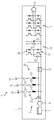
- the sole FIGURE schematically shows a mining vehicle 1 with an electric traction motor 3 and an energy supply system 5 of the mining vehicle 1.
- the power supply system 5 includes an engine 7 of the mining vehicle 1, for example, a diesel engine, an alternator driven by the engine 7 9, a catenary system 11, a coupling converter 13, a DC intermediate circuit 15 with DC link capacitor 27 and a traction converter 17.
- an engine 7 of the mining vehicle for example, a diesel engine, an alternator driven by the engine 7 9, a catenary system 11, a coupling converter 13, a DC intermediate circuit 15 with DC link capacitor 27 and a traction converter 17.
- the catenary system 11 of this embodiment is a catenary network with a catenary 19 for supplying the mining vehicle 1 with a three-phase AC supply voltage.
- the AC supply voltage of the trolley network can be applied to the coupling converter 13 via current collectors 21 connected to the overhead line 19.
- the catenary system 11 via an inductive coupling 22 with the traction converter 17 via the coupling converter 13 and the DC voltage intermediate circuit 15 is electrically connected.
- the inductive coupling 22 is formed in this embodiment of decoupling inductors 23, which electrically connect a current collector 21 to the coupling converter 13, respectively.
- the catenary system 11 and the alternator 9 are independently electrically connected to the coupling converter 13, so that either only the AC supply voltage or only the AC generator voltage or both the AC supply voltage and the AC generator voltage or neither the AC supply voltage nor the AC generator voltage to the coupling converter 13th is applied.
- the DC voltage intermediate circuit 15 electrically connects the coupling converter 13 to the traction converter 17, the coupling converter 13 converting the AC supply voltage and / or the generator AC voltage applied thereto into a DC link DC voltage of the DC intermediate circuit 15.
- the traction converter 17 is designed as a power converter, for example as an inverter, which converts the DC link voltage into an AC drive voltage for the traction motor 3.
- the DC voltage intermediate circuit 15 comprises a DC link capacitor 27, a DC link resistor 29 and a brake plate 31, which are electrically connected in parallel to each other and to each of which the intermediate circuit DC voltage is applied.
- the brake plate 31 is used to brake the traction motor 3 and includes a braking resistor 33 and an associated brake plate power electronics 35th
- the AC supply voltage of the catenary system 11 is selected such that its effective value is about as large as an effective value of the generator AC voltage generated by the AC generator 9.
- the AC supply voltage has an effective value in a range from 1.3 kV to 1.4 kV.
- the coupling power converter 13 can be configured as a feed-in power converter, for example as a B6 bridge or as an active front end (for example for energy recovery or for DC link voltage control option and / or regulation of the alternator 9), with the electrical energy from the DC voltage intermediate circuit 15 in the catenary system 11 can be fed. This allows braking energy of the drive motor 3, z. B. during braking or downhill, to be fed back to the voltage support in the catenary system 11.
Landscapes
- Engineering & Computer Science (AREA)
- Power Engineering (AREA)
- Transportation (AREA)
- Mechanical Engineering (AREA)
- Mining & Mineral Resources (AREA)
- Life Sciences & Earth Sciences (AREA)
- General Life Sciences & Earth Sciences (AREA)
- Geochemistry & Mineralogy (AREA)
- Geology (AREA)
- Sustainable Development (AREA)
- Sustainable Energy (AREA)
- Electric Propulsion And Braking For Vehicles (AREA)
Priority Applications (1)
| Application Number | Priority Date | Filing Date | Title |
|---|---|---|---|
| EP15201975.8A EP3184351A1 (fr) | 2015-12-22 | 2015-12-22 | Systeme d'alimentation en energie pour une vehicule de chantiers miniers et vehicule de chantiers miniers |
Applications Claiming Priority (1)
| Application Number | Priority Date | Filing Date | Title |
|---|---|---|---|
| EP15201975.8A EP3184351A1 (fr) | 2015-12-22 | 2015-12-22 | Systeme d'alimentation en energie pour une vehicule de chantiers miniers et vehicule de chantiers miniers |
Publications (1)
| Publication Number | Publication Date |
|---|---|
| EP3184351A1 true EP3184351A1 (fr) | 2017-06-28 |
Family
ID=55027421
Family Applications (1)
| Application Number | Title | Priority Date | Filing Date |
|---|---|---|---|
| EP15201975.8A Withdrawn EP3184351A1 (fr) | 2015-12-22 | 2015-12-22 | Systeme d'alimentation en energie pour une vehicule de chantiers miniers et vehicule de chantiers miniers |
Country Status (1)
| Country | Link |
|---|---|
| EP (1) | EP3184351A1 (fr) |
Cited By (4)
| Publication number | Priority date | Publication date | Assignee | Title |
|---|---|---|---|---|
| WO2020025376A1 (fr) * | 2018-07-31 | 2020-02-06 | Siemens Aktiengesellschaft | Convertisseur de puissance modulaire |
| CN113165529A (zh) * | 2018-11-29 | 2021-07-23 | 索尤若驱动有限及两合公司 | 具有耗电设备的系统 |
| CN113300579A (zh) * | 2020-02-24 | 2021-08-24 | 株洲中车时代电气股份有限公司 | 一种工程车的多源供电设备及系统 |
| CN113799663A (zh) * | 2021-11-19 | 2021-12-17 | 西南交通大学 | 一种动车供电传动系统、交直交牵引变流器及其控制方法 |
Citations (8)
| Publication number | Priority date | Publication date | Assignee | Title |
|---|---|---|---|---|
| DE2756983A1 (de) * | 1977-12-21 | 1979-06-28 | Kone Oy | Elektrisch betriebene lasttransportvorrichtung |
| EP0157192A2 (fr) * | 1984-03-08 | 1985-10-09 | Asea Ab | Méthode et dispositif pour relier une prise de courant d'un véhicule à trolley à un système à rails conducteurs |
| US5221880A (en) * | 1992-10-15 | 1993-06-22 | Balco, Inc. | Underground trolley vehicle with brushless D.C. Motor |
| DE102008009512A1 (de) * | 2008-02-15 | 2009-09-03 | Bombardier Transportation Gmbh | Versorgung von Hilfsbetrieben in einem Schienenfahrzeug mit elektrischer Energie |
| DE102009008549A1 (de) * | 2009-02-12 | 2010-08-19 | Bombardier Transportation Gmbh | Anordnung zum Betreiben von Verbrauchern in einem Schienenfahrzeug mit elektrischer Energie, wahlweise aus einem Energieversorgungsnetz oder aus einer Motor-Generator-Kombination |
| US20110094841A1 (en) * | 2009-10-23 | 2011-04-28 | Siemens Industry, Inc. | System and Method for Reinjection of Retard Energy in a Trolley-Based Electric Mining Haul Truck |
| US20130192944A1 (en) * | 2012-01-31 | 2013-08-01 | Joy Mm Delaware, Inc. | Overhead power grid for mobile mining machines |
| EP2705972A1 (fr) * | 2012-09-10 | 2014-03-12 | Sandvik Mining and Construction Oy | Véhicule d'exploitation minière |
-
2015
- 2015-12-22 EP EP15201975.8A patent/EP3184351A1/fr not_active Withdrawn
Patent Citations (8)
| Publication number | Priority date | Publication date | Assignee | Title |
|---|---|---|---|---|
| DE2756983A1 (de) * | 1977-12-21 | 1979-06-28 | Kone Oy | Elektrisch betriebene lasttransportvorrichtung |
| EP0157192A2 (fr) * | 1984-03-08 | 1985-10-09 | Asea Ab | Méthode et dispositif pour relier une prise de courant d'un véhicule à trolley à un système à rails conducteurs |
| US5221880A (en) * | 1992-10-15 | 1993-06-22 | Balco, Inc. | Underground trolley vehicle with brushless D.C. Motor |
| DE102008009512A1 (de) * | 2008-02-15 | 2009-09-03 | Bombardier Transportation Gmbh | Versorgung von Hilfsbetrieben in einem Schienenfahrzeug mit elektrischer Energie |
| DE102009008549A1 (de) * | 2009-02-12 | 2010-08-19 | Bombardier Transportation Gmbh | Anordnung zum Betreiben von Verbrauchern in einem Schienenfahrzeug mit elektrischer Energie, wahlweise aus einem Energieversorgungsnetz oder aus einer Motor-Generator-Kombination |
| US20110094841A1 (en) * | 2009-10-23 | 2011-04-28 | Siemens Industry, Inc. | System and Method for Reinjection of Retard Energy in a Trolley-Based Electric Mining Haul Truck |
| US20130192944A1 (en) * | 2012-01-31 | 2013-08-01 | Joy Mm Delaware, Inc. | Overhead power grid for mobile mining machines |
| EP2705972A1 (fr) * | 2012-09-10 | 2014-03-12 | Sandvik Mining and Construction Oy | Véhicule d'exploitation minière |
Cited By (6)
| Publication number | Priority date | Publication date | Assignee | Title |
|---|---|---|---|---|
| WO2020025376A1 (fr) * | 2018-07-31 | 2020-02-06 | Siemens Aktiengesellschaft | Convertisseur de puissance modulaire |
| RU2764004C1 (ru) * | 2018-07-31 | 2022-01-12 | Сименс Акциенгезелльшафт | Модульный вентильный преобразователь |
| US11424688B2 (en) | 2018-07-31 | 2022-08-23 | Siemens Aktiengesellschaft | Modular power converter |
| CN113165529A (zh) * | 2018-11-29 | 2021-07-23 | 索尤若驱动有限及两合公司 | 具有耗电设备的系统 |
| CN113300579A (zh) * | 2020-02-24 | 2021-08-24 | 株洲中车时代电气股份有限公司 | 一种工程车的多源供电设备及系统 |
| CN113799663A (zh) * | 2021-11-19 | 2021-12-17 | 西南交通大学 | 一种动车供电传动系统、交直交牵引变流器及其控制方法 |
Similar Documents
| Publication | Publication Date | Title |
|---|---|---|
| DE102013216700B4 (de) | Ladung von batteriefahrtfähigen Straßenfahrzeugen | |
| EP2996898B1 (fr) | Unité d'entraînement pour la commande d'un moteur | |
| DE102010039886B4 (de) | Antriebssystem für ein batteriebetriebenes Fahrzeug | |
| DE102009044281A1 (de) | Vorrichtung zum Übertragen von Energie mittels Leistungselektronik und Maschineninduktivität, und Verfahren zur Herstellung derselben | |
| DE102013200019B4 (de) | Versorgung von elektrischen Traktionsmotoren eines Schienenfahrzeugs mit elektrischer Energie unter Verwendung einer Mehrzahl von Verbrennungsmotoren | |
| WO2010091899A1 (fr) | Dispositif permettant de faire fonctionner, avec une énergie électrique provenant au choix d'un réseau d'alimentation ou d'un groupe motogénérateur, des équipements consommateurs d'énergie montés dans un véhicule ferroviaire | |
| DE102011079315A1 (de) | System mit Batterieladegerät und Bordnetzversorgungsstufe | |
| EP3184351A1 (fr) | Systeme d'alimentation en energie pour une vehicule de chantiers miniers et vehicule de chantiers miniers | |
| DE102017213306A1 (de) | Energieversorgungseinrichtung für ein Schienenfahrzeug | |
| CH711843B1 (de) | Oberleitungsbus mit einem Trenntransformator in der Stromversorgung. | |
| DE102013011104A1 (de) | Elektrische Energieverteilungseinrichtung für ein elektrisch angetriebenes Fahrzeug sowie Verfahren zum Betrieb der Energieverteilungseinrichtung | |
| DE102012007158A1 (de) | Pulswechselrichter mit Stromzwischenkreis zum Fahren und Laden eines batteriebetriebenen Elektrofahrzeugs | |
| EP4341123A1 (fr) | Alimentation électrique pour un véhicule ferroviaire présentant une batterie de traction | |
| DE102017212853A1 (de) | Hochintegriertes Stromrichtersystem und Kraftfahrzeug | |
| DE102012208241A1 (de) | Schienenfahrzeugsschaltungsanordnung | |
| DE102019129949A1 (de) | Autowaggon | |
| EP2399800A2 (fr) | Véhicule sur rail | |
| EP4201782B1 (fr) | Ensemble de propulsion d'une locomotive, comprenant différents systèmes de fourniture d'énergie | |
| DE19823233A1 (de) | Vorrichtung zur Speisung von gleichstrombetriebenen Fahrzeugen | |
| EP3626509B1 (fr) | Véhicule sur rail | |
| DE102012214864A1 (de) | Fahrzeug für den Streckennetz- und den Batteriebetrieb | |
| DE102016222856A1 (de) | Elektrisches Netzwerk für ein Schienenfahrzeug, Schienenfahrzeug und Verfahren zum Betrieb eines elektrischen Netzwerks | |
| DE102016201561A1 (de) | Schienenfahrzeugverbund | |
| EP2141044A2 (fr) | Véhicule sur rail et procédé d'alimentation en énergie d'un véhicule sur rail | |
| WO2024146716A1 (fr) | Alimentation électrique pour un véhicule ferroviaire présentant une batterie de traction |
Legal Events
| Date | Code | Title | Description |
|---|---|---|---|
| PUAI | Public reference made under article 153(3) epc to a published international application that has entered the european phase |
Free format text: ORIGINAL CODE: 0009012 |
|
| AK | Designated contracting states |
Kind code of ref document: A1 Designated state(s): AL AT BE BG CH CY CZ DE DK EE ES FI FR GB GR HR HU IE IS IT LI LT LU LV MC MK MT NL NO PL PT RO RS SE SI SK SM TR |
|
| AX | Request for extension of the european patent |
Extension state: BA ME |
|
| RAP1 | Party data changed (applicant data changed or rights of an application transferred) |
Owner name: SIEMENS AKTIENGESELLSCHAFT |
|
| STAA | Information on the status of an ep patent application or granted ep patent |
Free format text: STATUS: THE APPLICATION IS DEEMED TO BE WITHDRAWN |
|
| 18D | Application deemed to be withdrawn |
Effective date: 20180103 |