EP3184683A1 - Système d'encodeur magnétique pour servomoteur de machine à coudre - Google Patents
Système d'encodeur magnétique pour servomoteur de machine à coudre Download PDFInfo
- Publication number
- EP3184683A1 EP3184683A1 EP16201624.0A EP16201624A EP3184683A1 EP 3184683 A1 EP3184683 A1 EP 3184683A1 EP 16201624 A EP16201624 A EP 16201624A EP 3184683 A1 EP3184683 A1 EP 3184683A1
- Authority
- EP
- European Patent Office
- Prior art keywords
- sewing machine
- machine drive
- ring
- incremental
- incremental track
- Prior art date
- Legal status (The legal status is an assumption and is not a legal conclusion. Google has not performed a legal analysis and makes no representation as to the accuracy of the status listed.)
- Withdrawn
Links
Images


Classifications
-
- D—TEXTILES; PAPER
- D05—SEWING; EMBROIDERING; TUFTING
- D05B—SEWING
- D05B69/00—Driving-gear; Control devices
- D05B69/10—Electrical or electromagnetic drives
- D05B69/12—Electrical or electromagnetic drives using rotary electric motors
-
- G—PHYSICS
- G01—MEASURING; TESTING
- G01D—MEASURING NOT SPECIALLY ADAPTED FOR A SPECIFIC VARIABLE; ARRANGEMENTS FOR MEASURING TWO OR MORE VARIABLES NOT COVERED IN A SINGLE OTHER SUBCLASS; TARIFF METERING APPARATUS; MEASURING OR TESTING NOT OTHERWISE PROVIDED FOR
- G01D5/00—Mechanical means for transferring the output of a sensing member; Means for converting the output of a sensing member to another variable where the form or nature of the sensing member does not constrain the means for converting; Transducers not specially adapted for a specific variable
- G01D5/12—Mechanical means for transferring the output of a sensing member; Means for converting the output of a sensing member to another variable where the form or nature of the sensing member does not constrain the means for converting; Transducers not specially adapted for a specific variable using electric or magnetic means
-
- D—TEXTILES; PAPER
- D05—SEWING; EMBROIDERING; TUFTING
- D05B—SEWING
- D05B19/00—Program-controlled sewing machines
- D05B19/02—Sewing machines having electronic memory or microprocessor control unit
- D05B19/12—Sewing machines having electronic memory or microprocessor control unit characterised by control of operation of machine
-
- D—TEXTILES; PAPER
- D05—SEWING; EMBROIDERING; TUFTING
- D05B—SEWING
- D05B69/00—Driving-gear; Control devices
- D05B69/22—Devices for stopping drive when sewing tools have reached a predetermined position
- D05B69/24—Applications of devices for indicating or ascertaining sewing-tool position
-
- D—TEXTILES; PAPER
- D05—SEWING; EMBROIDERING; TUFTING
- D05B—SEWING
- D05B69/00—Driving-gear; Control devices
- D05B69/28—Applications of servo devices for tool-positioning purposes
-
- D—TEXTILES; PAPER
- D05—SEWING; EMBROIDERING; TUFTING
- D05B—SEWING
- D05B69/00—Driving-gear; Control devices
- D05B69/30—Details
-
- G—PHYSICS
- G01—MEASURING; TESTING
- G01B—MEASURING LENGTH, THICKNESS OR SIMILAR LINEAR DIMENSIONS; MEASURING ANGLES; MEASURING AREAS; MEASURING IRREGULARITIES OF SURFACES OR CONTOURS
- G01B7/00—Measuring arrangements characterised by the use of electric or magnetic techniques
- G01B7/003—Measuring arrangements characterised by the use of electric or magnetic techniques for measuring position, not involving coordinate determination
-
- G—PHYSICS
- G01—MEASURING; TESTING
- G01P—MEASURING LINEAR OR ANGULAR SPEED, ACCELERATION, DECELERATION, OR SHOCK; INDICATING PRESENCE, ABSENCE, OR DIRECTION, OF MOVEMENT
- G01P3/00—Measuring linear or angular speed; Measuring differences of linear or angular speeds
- G01P3/42—Devices characterised by the use of electric or magnetic means
Definitions
- the invention relates to a sewing machine drive.
- Sewing machine drives are known in many types, for example from the DE 19 714 520 A1 ,
- An object of the present invention is to further develop a sewing machine drive so that with a given security of a signal transmission, a design effort is reduced.
- the disk may be rotatably connected to a rotatable shaft, in particular to a motor shaft.
- a certain degree of contamination of an associated encoder system is to be expected, which z. B. difficult optical detection.
- the incremental marks are made as a full ring incremental track over 360 ° along a circumference of the disk and as an additional ring portion incremental track covering a portion of the disk.
- the magnetic incremental markings make it possible, for example, to considerably reduce the constructional outlay, in particular for sealing an encoder housing, since soiling does not impair the magnetic flux.
- no specially sealed bearings, z in particular no specially sealed bearings, z.
- the detectable signals of both incremental tracks can be fed to independent signal evaluations. More than two incremental tracks can also be used. Also more than two ring section incremental tracks can be used.
- the individual annular section incremental tracks may extend to different extents on the peripheries on the disc, which z. B. allows a direction of rotation detection.
- the incremental tracks may be applied to a ceiling wall and / or on a bottom wall of the disc.
- the incremental tracks may be applied to an outer perimeter of the disk.
- the incremental tracks may be applied to an outer shell wall of the disc.
- the disc can be made of ferritic material.
- the sewing machine drive can be designed as a servomotor.
- a sewing machine drive with magnetic encoder system allows optimized driveability of the drive, in particular a sewing machine motor, and thus can facilitate the handling of a sewing machine.
- An encoder system is known from the DE 39 90 206 T1 .
- Other encoder systems are known from the US 4,551,676 A , of the US 2015/0091554 A1 and the US 4,987,040 A ,
- a Ringinkrementalspur according to claim 2 allows a safe and trouble-free determination of position and speed information. As far as a 1: 1 ratio between a rotor of the motor and the disc is ensured, the speed of a motor shaft of the motor corresponds to the speed of the magnetic disc.
- a ring section incremental track according to claim 3 is used for zero point referencing of the rotor.
- the evaluation of the position and rotational speed information of the ring incremental track according to claim 4 takes place by means of an evaluation unit with integrated microcontroller and with magnetic sensors. This ensures a compact encoder system.
- another, separate magnetic sensor is used to detect the ring section incremental track. This sensor thus enables independent zero point referencing.
- An encoder system assembly 1 is for mounting a magnetic encoder system 2 to a servomotor for a sewing machine.
- the assembly 1 includes, in addition to the magnetic encoder system 2 a mounting flange 3.
- the magnetic encoder system 2 is attached to the servo motor.
- a motor shaft 4 of the servo motor is performed.
- An annular, surrounding magnetic passage, in particular ferrite disc 5 of the magnetic encoder system 2 is rotatably connected to the motor shaft 4 of the servomotor.
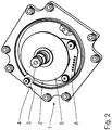
- an evaluation unit 7 On an additionally mounted on the mounting flange 3 plate 6 is an evaluation unit 7. This is stationary to the mounting flange 3 executed (see. Fig. 2 ).
- the magnetic encoder system 2 comprises, in addition to the evaluation unit 7, a full ring incremental track 8 and a ring section incremental track 9 (cf. Fig. 3 ).
- the full ring incremental track 8 and the ring section incremental track 9 extend along a circumference of the magnetic disk 5, the ring section incremental track 9 comprising only a partial section of the circumference.
- Incremental tracks 8, 9 have alternating north pole elements 10 and south pole elements 11.
- the incremental tracks 8 and 9 are arranged coaxially with one another and with respect to the motor shaft 4, wherein a radius R A of the ring section incremental track 9 is smaller than a radius Rv of the full-ring incremental track 8 (cf. Fig. 3 ).
- the evaluation unit 7 is arranged opposite the magnetic disk 5 in such a way that a first, not shown magnetic sensor of the evaluation unit 7 detects the full-ring incremental track 8 and a further, unspecified magnetic sensor of the evaluation unit 7 detects the ring portion incremental track 9.
- the two magnetic sensors are arranged radially offset from each other.
- annular section incremental tracks may also be provided. Peripheral extents of the ring sections of these annular section incremental tracks may differ from each other. If in such a case, for example, two or three annular incremental tracks are provided with circumferentially differing circumferential extents, in principle a direction of rotation detection is possible with such a variant of the encoder system. In such case, two different types of perimeter suffice. For example, a sequence "short / long / long" can be distinguished from a sequence "long / long / short” for detecting the direction of rotation.
Landscapes
- Engineering & Computer Science (AREA)
- Textile Engineering (AREA)
- Mechanical Engineering (AREA)
- Physics & Mathematics (AREA)
- General Physics & Mathematics (AREA)
- Electromagnetism (AREA)
- Computer Hardware Design (AREA)
- Microelectronics & Electronic Packaging (AREA)
- Transmission And Conversion Of Sensor Element Output (AREA)
- Sewing Machines And Sewing (AREA)
Applications Claiming Priority (1)
| Application Number | Priority Date | Filing Date | Title |
|---|---|---|---|
| DE102015226666.4A DE102015226666A1 (de) | 2015-12-23 | 2015-12-23 | Magnetisches Encodersystem für einen Servomotor einer Nähmaschine |
Publications (1)
| Publication Number | Publication Date |
|---|---|
| EP3184683A1 true EP3184683A1 (fr) | 2017-06-28 |
Family
ID=57471693
Family Applications (1)
| Application Number | Title | Priority Date | Filing Date |
|---|---|---|---|
| EP16201624.0A Withdrawn EP3184683A1 (fr) | 2015-12-23 | 2016-12-01 | Système d'encodeur magnétique pour servomoteur de machine à coudre |
Country Status (4)
| Country | Link |
|---|---|
| US (1) | US20170183800A1 (fr) |
| EP (1) | EP3184683A1 (fr) |
| CN (1) | CN106959124A (fr) |
| DE (1) | DE102015226666A1 (fr) |
Families Citing this family (3)
| Publication number | Priority date | Publication date | Assignee | Title |
|---|---|---|---|---|
| EP3695041B1 (fr) | 2017-10-13 | 2022-10-05 | Frankl & Kirchner GmbH & Co KG Fabrik für Elektromotoren u. elektrische Apparate | Entrainement de machine à coudre |
| TWI774322B (zh) * | 2021-04-15 | 2022-08-11 | 賀欣機械廠股份有限公司 | 縫紉機馬達之旋轉軸感測裝置 |
| CN115224881B (zh) * | 2021-04-16 | 2026-01-23 | 贺欣机械厂股份有限公司 | 缝纫机马达的旋转轴感测装置 |
Citations (12)
| Publication number | Priority date | Publication date | Assignee | Title |
|---|---|---|---|---|
| DE2135777A1 (de) * | 1971-07-16 | 1973-02-01 | Quick Rotan Becker & Notz Kg | Sollwertgeber fuer elektrische antriebe |
| DE2848612B1 (de) * | 1978-11-09 | 1980-02-21 | Pfaff Haushaltmasch | Impulsgeber fuer drehzahlgeregelte Antriebe |
| EP0103364A2 (fr) * | 1982-08-30 | 1984-03-21 | Microdynamics, Inc. | Méthode et dispositif pour ralentir la vitesse d'un moteur d'une machine à coudre avant l'arrêt |
| US4551676A (en) | 1982-03-02 | 1985-11-05 | Fanuc Ltd | Pulse coder using magnetoresistance elements having an improved z-phase signal pattern |
| EP0334018A1 (fr) * | 1988-03-22 | 1989-09-27 | Frankl & Kirchner GmbH. & Co. KG Fabrik für Elektromotoren und elektrische Apparate | Détecteur de position |
| DE3990206T1 (fr) | 1988-03-15 | 1990-04-05 | ||
| US4987040A (en) | 1987-09-16 | 1991-01-22 | Yamaha Corporation | Magnetic recording medium for displacement detectors |
| US5176085A (en) * | 1988-12-23 | 1993-01-05 | Mitsubishi Denki K.K. | Position detecting device |
| DE19714520A1 (de) | 1996-04-08 | 1997-10-30 | Brother Ind Ltd | Nähmaschine |
| WO2010124626A1 (fr) * | 2009-04-30 | 2010-11-04 | 浙江关西电机有限公司 | Machine à coudre électrique |
| JP2014161373A (ja) * | 2013-02-21 | 2014-09-08 | Aisin Seiki Co Ltd | ミシン |
| US20150091554A1 (en) | 2012-04-20 | 2015-04-02 | The Timken Company | Magnetic encoder for producing an index signal |
Family Cites Families (13)
| Publication number | Priority date | Publication date | Assignee | Title |
|---|---|---|---|---|
| US4584954A (en) * | 1981-07-10 | 1986-04-29 | Mitsubishi Denki Kabushiki Kaisha | Detector for use on sewing machines |
| JPS5860215A (ja) * | 1981-10-06 | 1983-04-09 | Hitachi Ltd | 位置検出付エンコ−ダ |
| JPS6148719A (ja) * | 1984-08-16 | 1986-03-10 | Fanuc Ltd | 光学式ロ−タリ−エンコ−ダ |
| US4895088A (en) * | 1988-06-01 | 1990-01-23 | Clinton Industries, Inc. | Accurate cutter system for sewing machine |
| JPH05337275A (ja) * | 1992-06-08 | 1993-12-21 | Aisin Seiki Co Ltd | ミシンの下糸残量検出装置 |
| US5998783A (en) * | 1994-06-01 | 1999-12-07 | Stridsberg Innovation Ab | Heat protected position transducer in an electric motor |
| FR2736428B1 (fr) * | 1995-07-04 | 1997-08-08 | Schlumberger Ind Sa | Encodeur impulsionnel pour appareil de distribution de liquide |
| FR2769088B1 (fr) * | 1997-09-26 | 1999-12-03 | Roulements Soc Nouvelle | Capteur digital de position relative |
| DE19949020C1 (de) * | 1999-10-11 | 2001-04-05 | Viking Sewing Machines Ab Husk | Nähmaschine mit einem ein Lüfterrad und einen Drehzahlgeber aufweisenden Elektromotor |
| EP1974185B1 (fr) * | 2006-01-12 | 2013-06-26 | Timken US Corporation | Capteur magnetique avec pistes haute et basse resolution |
| KR101228733B1 (ko) * | 2006-04-10 | 2013-02-01 | 팀켄 유에스 엘엘씨 | 선회 장치 위치 감지 시스템 및 방법 |
| DE112009000497B4 (de) * | 2008-03-17 | 2012-12-13 | Mitsubishi Electric Corp. | Ursprungspositions-Signaldetektor |
| TWI502459B (zh) * | 2013-07-08 | 2015-10-01 | Acer Inc | 電子裝置及其觸控操作方法 |
-
2015
- 2015-12-23 DE DE102015226666.4A patent/DE102015226666A1/de not_active Withdrawn
-
2016
- 2016-12-01 EP EP16201624.0A patent/EP3184683A1/fr not_active Withdrawn
- 2016-12-14 US US15/378,424 patent/US20170183800A1/en not_active Abandoned
- 2016-12-23 CN CN201611205360.0A patent/CN106959124A/zh active Pending
Patent Citations (12)
| Publication number | Priority date | Publication date | Assignee | Title |
|---|---|---|---|---|
| DE2135777A1 (de) * | 1971-07-16 | 1973-02-01 | Quick Rotan Becker & Notz Kg | Sollwertgeber fuer elektrische antriebe |
| DE2848612B1 (de) * | 1978-11-09 | 1980-02-21 | Pfaff Haushaltmasch | Impulsgeber fuer drehzahlgeregelte Antriebe |
| US4551676A (en) | 1982-03-02 | 1985-11-05 | Fanuc Ltd | Pulse coder using magnetoresistance elements having an improved z-phase signal pattern |
| EP0103364A2 (fr) * | 1982-08-30 | 1984-03-21 | Microdynamics, Inc. | Méthode et dispositif pour ralentir la vitesse d'un moteur d'une machine à coudre avant l'arrêt |
| US4987040A (en) | 1987-09-16 | 1991-01-22 | Yamaha Corporation | Magnetic recording medium for displacement detectors |
| DE3990206T1 (fr) | 1988-03-15 | 1990-04-05 | ||
| EP0334018A1 (fr) * | 1988-03-22 | 1989-09-27 | Frankl & Kirchner GmbH. & Co. KG Fabrik für Elektromotoren und elektrische Apparate | Détecteur de position |
| US5176085A (en) * | 1988-12-23 | 1993-01-05 | Mitsubishi Denki K.K. | Position detecting device |
| DE19714520A1 (de) | 1996-04-08 | 1997-10-30 | Brother Ind Ltd | Nähmaschine |
| WO2010124626A1 (fr) * | 2009-04-30 | 2010-11-04 | 浙江关西电机有限公司 | Machine à coudre électrique |
| US20150091554A1 (en) | 2012-04-20 | 2015-04-02 | The Timken Company | Magnetic encoder for producing an index signal |
| JP2014161373A (ja) * | 2013-02-21 | 2014-09-08 | Aisin Seiki Co Ltd | ミシン |
Also Published As
| Publication number | Publication date |
|---|---|
| US20170183800A1 (en) | 2017-06-29 |
| DE102015226666A1 (de) | 2017-06-29 |
| CN106959124A (zh) | 2017-07-18 |
Similar Documents
| Publication | Publication Date | Title |
|---|---|---|
| EP3411667B1 (fr) | Procédé de calibration d'un codeur rotatif et codeur rotatif pour déterminer une position angulaire corrigée | |
| EP3208054B1 (fr) | Entraînement d'articulation de robot avec codeur | |
| EP1670121B2 (fr) | Machine électrique, moteur à courant continu sans balais en particulier | |
| EP3403056B1 (fr) | Assemblage d'un détecteur de rotation à un boîtier | |
| EP3037795B1 (fr) | Capteur d'angle et de couple et mecanisme de commande | |
| EP2678922B1 (fr) | Dispositif pour déterminer la position angulaire d'un arbre et d'un moteur électrique | |
| DE102007042478A1 (de) | Wälzlagereinrichtung mit integriertem Sensorsystem | |
| DE102007011675A1 (de) | Lenkwinkel- und Drehmomentsensor in einer Hilfskraftlenkung eines Kraftfahrzeugs | |
| DE19961884C2 (de) | Anordnung zur kontaktlosen Erfassung von Drehwinkeln, Drehmomenten und sonstigen, vorzugsweise rotatorischen Grössen zwischen rotierenden Teilen | |
| DE102010018724A1 (de) | Induktiver Drehwinkelsensor | |
| DE102015102013A1 (de) | Sensorvorrichtung mit einer Drehmomentsensoreinrichtung und einer Inkrementalsensoreinrichtung und Kraftfahrzeug mit einer solchen Sensorvorrichtung | |
| DE102018217274A1 (de) | Radnabenanordnung mit dualen Winkelpositionssensoren | |
| DE102015226666A1 (de) | Magnetisches Encodersystem für einen Servomotor einer Nähmaschine | |
| DE102009023691A1 (de) | Anordnung zur Bestimmung der Winkelstellung einer Welle und Elektromotor | |
| DE112016007441T5 (de) | Drehpositionserkennungsvorrichtung | |
| DE102004032695B4 (de) | Lageranordnung für die Nabe eines Kraftfahrzeugrades | |
| DE102006015065A1 (de) | Einbaumotor, insbesondere Einbau-Torquemotor | |
| DE102014014391A1 (de) | Kombiniertes Sensorkonzept für Lenksysteme von Kraftfahrzeugen | |
| DE10258846A1 (de) | Einrichtung zur Drehwinkelerfassung eines drehbaren Elements | |
| DE4324622A1 (de) | Vorrichtung zum Erfassen einer Drehbewegung | |
| DE102011076284A1 (de) | Lagereinheit mit Winkelmesssystem | |
| DE102004009839A1 (de) | Drehwinkelsensor | |
| WO2002084849A1 (fr) | Procede et dispositif pour determiner la position angulaire d'un generateur electrique a induction | |
| EP3128294B1 (fr) | Capteur de determination de la position angulaire d'un moteur et moteur comprenant un capteur destine a determiner la position angulaire | |
| EP3057850B1 (fr) | Système de capteur de détection d'angles de rotation d'un composant rotatif dans un véhicule |
Legal Events
| Date | Code | Title | Description |
|---|---|---|---|
| PUAI | Public reference made under article 153(3) epc to a published international application that has entered the european phase |
Free format text: ORIGINAL CODE: 0009012 |
|
| AK | Designated contracting states |
Kind code of ref document: A1 Designated state(s): AL AT BE BG CH CY CZ DE DK EE ES FI FR GB GR HR HU IE IS IT LI LT LU LV MC MK MT NL NO PL PT RO RS SE SI SK SM TR |
|
| AX | Request for extension of the european patent |
Extension state: BA ME |
|
| STAA | Information on the status of an ep patent application or granted ep patent |
Free format text: STATUS: THE APPLICATION IS DEEMED TO BE WITHDRAWN |
|
| 18D | Application deemed to be withdrawn |
Effective date: 20180103 |