EP3184708A1 - Crochet de suspension et d'inclinaison - Google Patents
Crochet de suspension et d'inclinaison Download PDFInfo
- Publication number
- EP3184708A1 EP3184708A1 EP16206489.3A EP16206489A EP3184708A1 EP 3184708 A1 EP3184708 A1 EP 3184708A1 EP 16206489 A EP16206489 A EP 16206489A EP 3184708 A1 EP3184708 A1 EP 3184708A1
- Authority
- EP
- European Patent Office
- Prior art keywords
- seat
- members
- face
- supported
- connection
- Prior art date
- Legal status (The legal status is an assumption and is not a legal conclusion. Google has not performed a legal analysis and makes no representation as to the accuracy of the status listed.)
- Granted
Links
Images


Classifications
-
- E—FIXED CONSTRUCTIONS
- E04—BUILDING
- E04B—GENERAL BUILDING CONSTRUCTIONS; WALLS, e.g. PARTITIONS; ROOFS; FLOORS; CEILINGS; INSULATION OR OTHER PROTECTION OF BUILDINGS
- E04B1/00—Constructions in general; Structures which are not restricted either to walls, e.g. partitions, or floors or ceilings or roofs
- E04B1/38—Connections for building structures in general
- E04B1/388—Separate connecting elements
-
- E—FIXED CONSTRUCTIONS
- E04—BUILDING
- E04B—GENERAL BUILDING CONSTRUCTIONS; WALLS, e.g. PARTITIONS; ROOFS; FLOORS; CEILINGS; INSULATION OR OTHER PROTECTION OF BUILDINGS
- E04B1/00—Constructions in general; Structures which are not restricted either to walls, e.g. partitions, or floors or ceilings or roofs
- E04B1/18—Structures comprising elongated load-supporting parts, e.g. columns, girders, skeletons
- E04B1/26—Structures comprising elongated load-supporting parts, e.g. columns, girders, skeletons the supporting parts consisting of wood
- E04B1/2604—Connections specially adapted therefor
- E04B1/2612—Joist hangers
-
- E—FIXED CONSTRUCTIONS
- E04—BUILDING
- E04B—GENERAL BUILDING CONSTRUCTIONS; WALLS, e.g. PARTITIONS; ROOFS; FLOORS; CEILINGS; INSULATION OR OTHER PROTECTION OF BUILDINGS
- E04B1/00—Constructions in general; Structures which are not restricted either to walls, e.g. partitions, or floors or ceilings or roofs
- E04B1/18—Structures comprising elongated load-supporting parts, e.g. columns, girders, skeletons
- E04B1/26—Structures comprising elongated load-supporting parts, e.g. columns, girders, skeletons the supporting parts consisting of wood
- E04B1/2604—Connections specially adapted therefor
- E04B2001/2644—Brackets, gussets or joining plates
-
- E—FIXED CONSTRUCTIONS
- E04—BUILDING
- E04B—GENERAL BUILDING CONSTRUCTIONS; WALLS, e.g. PARTITIONS; ROOFS; FLOORS; CEILINGS; INSULATION OR OTHER PROTECTION OF BUILDINGS
- E04B1/00—Constructions in general; Structures which are not restricted either to walls, e.g. partitions, or floors or ceilings or roofs
- E04B1/38—Connections for building structures in general
- E04B1/388—Separate connecting elements
- E04B2001/389—Brackets
Definitions
- This invention relates to a connector for joining structural members and the connection made therewith.
- the present invention has particular application as a simple, inexpensive hanger for strengthening a connection between a ridge or valley member and a sloping and skewed rafter member or joist.
- US Patent 4,423,977 granted in 1984 to Tyrell T. Gilb , which is hereby incorporated by reference, provides a good background of the history of patented slope and skew connections.
- the inventor spent much time discussing the problems with early solutions that required the notching of the sloped rafter or joist members.
- a typical hanger has a seat member to support the joist and the seat member is typically disposed orthogonally with respect to the attachment face of the support member; that is to say, typically the seat of the hanger juts out horizontally. This is ideal for most floor and wall connections where the joists themselves are disposed horizontally and the bottom of the joist rests on the seat of the hanger.
- the bottom of the sloped rafter or jack member will typically be disposed at a slope that is not horizontal.
- a typical hanger with a horizontal seat can be an acceptable choice if the joist or rafter can be notched to create a small horizontal face that rests on the seat of the hanger.
- notching the rafter takes time, and some rafters, particularly I-joists, cannot or should only be notched in very limited situations.
- inventors have sought to create hangers for sloped connections where the seat of the hanger is disposed at a sloped angle to interface with the base of the rafter or joist. This way the joist or rafter does not have to be notched if the user wants to have interfacing contact between a seat on the hanger and the bottom surface of the joist.
- US Patent 4,423,977 teaches a simple slope and skew hanger that is made from cutting a blank of sheet metal and cold-forming bends in the sheet metal. Some of the bends can be modified on site during final installation by what is known in the art as field bending.
- Gilb's single-piece, sheet metal hanger accommodates attaching a rafter or a joist member disposed at varying slopes and skew angles with respect to the ridge member.
- the Gilb hanger of US Patent 4,423,977 could accommodate joists or rafters at varying slopes because the seat member was not directly connected to the side members or jutting tabs that interfaced with the joist and steadied the joist. The seat member was free to bend to interface with the bottom of the joist at a variety of angles.
- US Patent 5,457,928, granted to George Sahnazarian in 1995 teaches a slope and skew hanger similar to the Gilb hanger of US Patent 4,423,977.
- Sahnazarian claimed adding ribs to the members that attached the hanger to the ridge member.
- US Patent 5,797,694, granted to Arne Norris Breivik in 1998 also teaches a slope and skew hanger similar to the Gilb hanger of US Patent 4,423,977. Breivik claimed shaping the members that attached the hanger to the ridge member in a particular manner.
- US Patent 7,503,148 granted to Jin-Jie Lin in 2009 , teaches a simple hanger that can accommodate multiple members at various skew angles.
- the Lin hanger can be modified in the field to the skew angles of the joist or joists, because, in a manner similar to the Gilb hanger, the side members or jutting tabs were not directly attached to the seat member.
- the present invention is a connector and connection made with that connector that like the prior art makes a sloped and skewed connection while providing additional features not found in the prior art.
- the present invention provides a connection between a supported member and a supporting member, the connection comprising:
- the present invention provides a connector that is easy to install when the supported member is already attached to and being held by the supporting member. Such an installation is called a retrofit installation.
- the back members of the present connector are spaced apart from each other a sufficient distance to accept the supported member between them with little or no contact between the left and right sides of the supported member and the back members, and with no contact between the back members and the end face of the supported member. In this way, the connector of the present invention can be inserted into position to engage the supported member and the supporting member to strengthen the connection.
- the back members of the connector are held in position by a generally planar seat member that is attached to the left and right back members at aligned left and right seat bend lines. This attachment of a generally planar seat member through left and right aligned seat bend lines to separated left and right back members results in a strong connector that can use fewer fasteners than similar connections.
- the present invention provides a connector that can support a held member with respect to a holding member with the held member being skewed (right or left) and sloped (up or down) at the same time.
- the present invention also provides a connector that can hold a supported member that can hang below the supporting member.
- the connector interfaces with the bottom face of the supported member, and extends upwardly along the attachment face of the supporting member where fasteners attach the connector to the supporting member.
- hanger is field bent along only three bend lines to provide slope and/or skew adjustments.
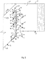
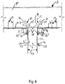
- the connector or hanger 1 of the present invention is designed to attach a supported member 2 to a supporting member 3 , with the supported member 2 being in sloped and skewed relation to the supporting member 3.
- the hanger 1 has left and right back members 4 and 5.
- Left and right side support members 6 and 7 are attached to the left and right back members 4 and 5 respectively.
- a seat member 8 attaches to both the left and right back members 4 and 5 along aligned left and right seat bend lines 9 and 10 .
- the preferred embodiment has a pair of left and right seat side members 11 and 12 extending upwardly from the seat member 8.
- the preferred embodiment is also formed with a pair of left and right jutting tabs 13 and 14 extending from the left and right back members 4 and 5 respectively on opposed sides from the left and right side support members 6 and 7.
- fasteners 15 are used to attach the connector 1 to the supported and supporting members 2 and 3.
- the fasteners 15 driven through the jutting tabs 13 and 14 can be driven at an angle such that they first enter the supported member 2 and then the supporting member 3 to strengthen the connection even further.
- the fastener 15 is preferably formed with a shank 16 having an end portion 17 and a middle portion 18 .
- the end portion 17 of the shank 16 of the fastener 15 is embedded in the supporting member 3 and the middle portion 18 of the shank 16 of the fastener 15 is embedded in the supported member 2.
- the fasteners 15 shown are nails, but screws and other similar fasteners may be used.
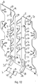
- the connector 1 is preferably formed with a combination of round fastener openings 19, restricted slot fastener openings 20 and fastener guides 21 to aid the user in positioning and driving the fasteners 15 that make the attachment.
- the supported member 2 is formed with left and right sides 22 and 23 that are generally parallel to each other and are spaced apart a first selected distance 24 .
- the supported member 2 is also formed with an end face 25 that meets with the left and right sides 22 and 23 of the supported member 2 at left and right side edges 26 and 27 of the end face 25.
- the supported member 2 can be formed with a top face 28 and a bottom face 29 that meet with the left and right sides 22 and 23 and the end face 25.
- the top and bottom faces 28 and 29 are generally parallel with each other and can be at a sloped angle to the generally vertically disposed end face 25.
- a sloping angle is an angle other than 90 degrees.
- the supporting member 3 has an attachment face 30 and a top face 31 that meets the attachment face 30 at a top edge 32 of the attachment face 30.
- the attachment face 30 is generally vertically disposed and the top face 31 of the supporting member 3 is generally horizontally disposed, although the top face 31 could also be at a sloped orientation.
- the connector 1 is formed with left and right back members 4 and 5.
- the left and right back members 4 and 5 are substantially planar members that lie in the same plane.
- the back members 4 and 5 are spaced apart from each other a sufficient distance to accept the supported member 2 between them with little or no contact between the left and right sides 22 and 23 of the supported member 2 and the back members 4 and 5, and with no contact between the back members 4 and 5 and the end face 25 of the supported member 2.
- the left and right back members 4 and 5 are each connected to the seat member 8, and are only connected to each other through the seat member 8.
- the seat member 8 is sufficiently strong to hold the left and right back members 4 and 5 in their spaced relationship.
- the left and right back members 4 and 5 are preferably formed with left and right embossments 33 and 34 near the left and right seat bend lines 9 and 10, respectively. These embossments 33 and 34 are preferably rectangular.
- the seat member 8 is preferably formed with left and right embossments 35 and 36 near the left and right seat bends lines 9 and 10.
- the embossments 35 and 36 of the seat member 8 are preferably rectangular members that are aligned with the left and right embossments 33 and 34 of the left and right back members 4 and 5 respectively.
- the left and right jutting tabs 13 and 14 are spaced apart from each other a sufficient distance to accept the supported member 2 between them; however, the jutting tabs 13 and 14 are bent so that they align with and register with the left and right sides 6 and 7 of the supported member 2.
- the left and right jutting tabs 13 and 14 attach to the left and right back members 4 and 5 along left and right tab bend lines 37 and 38 on the inner side edges 39 and 40 of the left and right back members 4 and 5, respectively.
- the left and right jutting tabs 13 and 14 are preferably formed with corresponding projections 41 and notches 42 to better space the fasteners 15 that are driven through the jutting tabs 13 and 14. This also maximizes the material of the jutting tabs 13 and 14 when cut from a sheet steel blank as is the preferred method of forming the connector 1.
- the connector 1 is preferably made from thin sheet steel that is formed on automated machinery.
- the seat member 8 is an integral part of the back members 4 and 5 of the hanger 1.
- the seat member 8 is preferably connected to the back members 4 and 5 at the bottom of the back members 4 and 5.
- the seat member 8 is a generally planar member.
- the seat member 8 is preferably connected to the back members 4 and 5 along aligned left and right seat bend lines 9 and 10.
- the seat member 8 is integrally connected to the back members 4 and 5 along the left and right seat bend lines 9 and 10.
- the seat member 8 extends angularly from the back members 4 and 5 a selected distance.
- the left and right back members 4 and 5 extend upwardly from the left and right seat bend lines 9 and 10, respectively.
- Above the left and right seat bend lines 9 and 10 the left and right back members 4 and 5 are spaced apart a second selected distance 43 that is greater than the first selected distance 24 between the left and right sides 6 and 7 of the supported member 2.
- left and right seat side members 11 and 12 are preferably integrally connected to opposed sides of the seat member 8 at left and right seat side bend lines 44 and 45 and extend generally parallel to each other and angularly to the seat member 8.
- the seat side members 11 and 12 are spaced apart a third selected distance 46 that is also greater than the first selected distance 24 between the left and right sides 22 and 23 of the supported member 2.
- the seat side members 11 and 12 preferably interface closely with the left and right sides 22 and 23 of the supported member 2.
- the seat member 8 may be set orthogonally from the back members 4 and 5, or the seat member 8 may slope upwardly or downwardly from 90 degrees.
- the upward slope may be up to 49 degrees with very little loss in load capacity.
- the hanger 1 can accommodate any upward slope to 45 degrees without a change in the allowable loads for the hanger. In some installations, between 45 degrees and 49 degrees, the allowable loads for the hanger 1 are slightly reduced.
- the downward slope may be as much as 49 degrees with only slight reduction in load capacity and with no difference in allowable loads up to slopes of 45 degrees downward.
- each back member 4 and 5 is formed with a jutting tab 13 and 14.
- the jutting tabs 13 and 14 extend generally parallel to each other and angularly to the back members 4 and 5 to which they are connected.
- the left and right jutting tabs 13 and 14 are preferably attached to left and right back inner side edges 39 and 40 of the left and right back members 4 and 5 respectively.
- Openings 19, 20 and 21 for the fasteners 15 can take a variety of shapes and forms. Where fasteners 15 must be driven at an acute angle through the connector 1 into one or both of the supported member 2 and the supporting member 3 it is preferable to form the fastener opening with a fastener guide 21 or other opening that helps direct the fastener 15 at the proper acute angle.
- US Patent 4,230,416, granted to Tyrell T. Gilb teaches a restricted slot nail opening 20.
- the opening is a slot-like opening having a length greater than its width.
- the width of the opening is selected to register with the sides of the fastener 15 that is driven through the opening.
- the extended length of the opening allows the fastener to be driven at a range of angles through the opening as compared to a circular opening that is close fitting with the shank of the fastener 15.
- the fastener 15 In a closely formed circular opening the fastener 15 must be driven generally orthogonally to the face of the connector 1.
- the side support members 6 and 7 are preferably formed with restricted slot fastener openings 20 as the side support members 6 and 7 can be bent at a variety of angles to the attachment face 30 of the supporting member 3 and thus the fasteners 15 can be driven at a variety of angles through the side support members 6 and 7.
- Gilb teaches a modified restricted slot nail opening that can guide a fastener 15 at a particular angle.
- Gilb called it a positive nail angling device.
- the positive nail angling device starts with a restricted slot nail opening.
- the width of the opening is selected to register with the sides of the fastener that is driven 15 through the opening.
- a tab-like member is formed from the displaced material from the slot-like opening and bent along a bend line which constitutes one end of the slit-like opening.
- the opening has an opposite end from the end from which the tab-like member is bent.
- the tab-like member is formed with a nail receiving surface for positively receiving a side of the fastener shank 16 in generally parallel, face to face relationship.
- the length of the slot-like opening and the displacement angle of the tab-like member are selected so that the fastener can only be driven at a pre-selected angle through the opening.
- One side of the shank 16 of the fastener 15 is in close fitting relation to the opposite end of the slot-like opening and the opposite side of the shank 16 of the fastener 15 is in touching or close fitting relation to the receiving surface of the tab-like member. If the tab is undisturbed, the fastener 15 can only be driven at a slant angle to the face of the connector 1.
- left and right side support members 6 and 7 are attached to the opposed left and right outer side edges 47 and 48 of the left and right back members 4 and 5.
- left and right longitudinally extending bend lines 49 and 50 are provided at the outer side edge 47 and 48 of each back member 4 and 5.
- the left and right longitudinally extending bend lines 49 and 50 separate each back member 4 and 5 from its adjacent left and right side support member 6 and 7.
- the left side support member 6 attaches to the left back member 4 along the left longitudinally extending bend line 49.
- the right side support member 7 attaches to the right back member 5 along the right longitudinally extending bend line 50.
- the left and right longitudinally extending bend lines 49 and 50 permit angular displacement of the side support members 6 and 7 for skewed attachment of the supported member 2 to the supporting member 3.
- the left side support member 6 is bent at a first angle
- the right side support member 7 is bent at a second angle. Bending of the side support members 6 and 7 with respect to the back members 4 and 5 is facilitated by the provision of slots 51 which are aligned withone another along the longitudinally extending bend lines 49 and 50 between the left and right back members 4 and 5 and the left and right side support members 6 and 7 respectively.
- Figures 1 , 2 and 4 illustrate the connector 1 skewed to the left, but a reversal of the direction or bending of the side support members 6 and 7 along the longitudinal bend lines 49 and 50 creates a rightwardly skewed connector.
- the retrofit connection when the supported member 2 is already attached to the supporting member 3, is formed by inserting the connector 1 of the present invention underneath the supported member 2.
- the supported member 2 is inserted between the jutting tabs 13 and 14 and the back members 4 and 5 of the present invention.
- the seat member 8 is then field bent to engage the bottom face 29 of the joist or supported member 2. If the connection is not skewed, the back members 4 and 5 are set to engage the attachment face 30 of the supporting member 3 and fasteners 15 are driven through the jutting tabs 13 and 14, the side support members 6 and 7 and the seat member 8 to make the connection. If the connection is skewed, the side support members 6 and 7 are field bent.
- the side support member 6 or 7 on the side of the connection where an acute angle is formed between the supported member 2 and the supporting member 3 is bent to interface and register in parallel relation with the attachment face 30 of the supporting member 3.
- the side support member 26 or 7 is bent to contact the attachment face 30 of the supporting member 3.
- Fasteners 15 are then driven through the side support member members 6 and 7, the jutting tabs 13 and 14 and the seat member 8 to make the connection.
Landscapes
- Engineering & Computer Science (AREA)
- Architecture (AREA)
- Physics & Mathematics (AREA)
- Electromagnetism (AREA)
- Civil Engineering (AREA)
- Structural Engineering (AREA)
- Joining Of Building Structures In Genera (AREA)
- Connection Of Plates (AREA)
- Floor Finish (AREA)
Applications Claiming Priority (1)
| Application Number | Priority Date | Filing Date | Title |
|---|---|---|---|
| US201562271153P | 2015-12-22 | 2015-12-22 |
Publications (2)
| Publication Number | Publication Date |
|---|---|
| EP3184708A1 true EP3184708A1 (fr) | 2017-06-28 |
| EP3184708B1 EP3184708B1 (fr) | 2021-02-03 |
Family
ID=57755041
Family Applications (1)
| Application Number | Title | Priority Date | Filing Date |
|---|---|---|---|
| EP16206489.3A Active EP3184708B1 (fr) | 2015-12-22 | 2016-12-22 | Crochet penché et incliné |
Country Status (3)
| Country | Link |
|---|---|
| US (1) | US10370842B2 (fr) |
| EP (1) | EP3184708B1 (fr) |
| AU (1) | AU2016277668B2 (fr) |
Cited By (1)
| Publication number | Priority date | Publication date | Assignee | Title |
|---|---|---|---|---|
| CN107700842A (zh) * | 2017-08-14 | 2018-02-16 | 上海二十冶建设有限公司 | 多级陡坡条件下高层吊脚楼群施工速度控制方法 |
Families Citing this family (15)
| Publication number | Priority date | Publication date | Assignee | Title |
|---|---|---|---|---|
| DE102016106357A1 (de) * | 2016-04-07 | 2017-10-12 | Wilhelm Layher Verwaltungs-Gmbh | Beschlag für ein Bordbrett eines Gerüsts |
| EP3523490B1 (fr) | 2016-10-05 | 2023-11-08 | Fortress Iron, LP | Système de charpente de tablier |
| US10619343B2 (en) * | 2017-06-06 | 2020-04-14 | Power Brace, LLC | Adjustable foundation support system |
| US10619323B2 (en) * | 2017-06-06 | 2020-04-14 | Power Brace, LLC | Adjustable foundation support system |
| US10889978B2 (en) * | 2017-12-21 | 2021-01-12 | Studco Australia Pty Ltd. | Method of connecting and installing a building member |
| US11028580B2 (en) * | 2018-05-25 | 2021-06-08 | Fortress Iron, Lp | Deck frame with integral attachment tabs |
| EP3911803A1 (fr) * | 2019-01-14 | 2021-11-24 | Simpson Strong-Tie Company, Inc. | Connecteur à charnière renforcé |
| US11118349B2 (en) * | 2020-01-29 | 2021-09-14 | Laura Montoya | Rafter reinforcement bracket apparatus |
| CA3180728A1 (fr) * | 2020-06-03 | 2021-12-09 | Peter BARENSKI Jr. | Dispositif de suspension reglable en hauteur avec element de compression |
| JP7463897B2 (ja) * | 2020-07-30 | 2024-04-09 | 積水ハウス株式会社 | 斜め梁接合金物および梁の接合構造 |
| US20240076866A1 (en) * | 2021-01-15 | 2024-03-07 | P & W Construction Materials and Consulting Ltd. | Brackets for insulated concrete forms and methods of manufacturing and installation thereof |
| CA3252020A1 (fr) * | 2022-04-18 | 2023-10-26 | Simpson Strong-Tie Company Inc. | Dispositif de suspension de plaque de couteau pour siège lourd |
| CA3221402A1 (fr) * | 2022-11-28 | 2024-05-28 | Omg, Inc. | Support a broches pour structures de construction |
| WO2024186694A1 (fr) * | 2023-03-03 | 2024-09-12 | Simpson Strong-Tie Company Inc | Connecteur pour murs préfabriqués |
| WO2025038814A2 (fr) * | 2023-08-15 | 2025-02-20 | GluDown, Inc. | Support d'entretoise pour paroi de coffrage |
Citations (9)
| Publication number | Priority date | Publication date | Assignee | Title |
|---|---|---|---|---|
| US4230416A (en) | 1979-10-15 | 1980-10-28 | Simpson Manufacturing Co., Inc. | Restricted slot nail openings for sheet metal framing connectors |
| US4291996A (en) | 1980-07-01 | 1981-09-29 | Simpson Manufacturing Co., Inc. | Positive nail angling device for metal connectors |
| US4423977A (en) | 1982-03-22 | 1984-01-03 | Simpson Strong-Tie Company, Inc. | Single element slope and skew hanger |
| US4480941A (en) * | 1983-03-04 | 1984-11-06 | Simpson Strong-Tie Company, Inc. | Double shear angled fastener connector |
| US4560301A (en) * | 1984-01-03 | 1985-12-24 | Simpson Strong-Tie, Company, Inc. | Heavy slope and skew sheet metal hanger and method of making same |
| US5457928A (en) | 1994-04-01 | 1995-10-17 | Mga Construction Hardware And Steel Fabricating Ltd. | Slope and skew hanger connectors |
| US5603580A (en) | 1995-05-30 | 1997-02-18 | Simpson Strong-Tie Company, Inc. | Positive angle fastener device |
| US5797694A (en) | 1996-03-29 | 1998-08-25 | Alpine Engineered Products, Inc. | Adjustable ridge connector |
| US7503148B2 (en) | 2006-10-31 | 2009-03-17 | Simpson Strong-Tie Company, Inc. | Quadruple mono truss connection |
Family Cites Families (42)
| Publication number | Priority date | Publication date | Assignee | Title |
|---|---|---|---|---|
| US508280A (en) | 1893-11-07 | Beam or girder support | ||
| GB185694A (en) | 1921-12-30 | 1922-09-14 | Baden Robert Rowell | Improved joint for floor joists and like weight supporting members |
| US2911690A (en) | 1956-12-18 | 1959-11-10 | Sanford Arthur Carol | Hanger strap |
| US3036347A (en) | 1957-05-31 | 1962-05-29 | Easybow Engineering & Res Co | Joist hanger |
| US2990590A (en) | 1958-07-31 | 1961-07-04 | Lite Vent Ind Inc | Awning rafter saddle tie |
| US3333875A (en) | 1965-01-07 | 1967-08-01 | Internat Entpr Inc | Bracket system for roof framing |
| US3596941A (en) | 1969-09-02 | 1971-08-03 | Int Enterprises Inc | Selectively adjustable roof bracket |
| US3601428A (en) * | 1969-12-11 | 1971-08-24 | Simpson Co | Pronged joist hanger |
| US4144683A (en) | 1977-07-05 | 1979-03-20 | Spiral-Craft | Bracket assembly |
| US4261155A (en) * | 1979-11-16 | 1981-04-14 | Simpson Manufacturing Co., Inc. | Infinite skewed hanger |
| US4330971A (en) * | 1980-08-04 | 1982-05-25 | Auberger Earl J | Wall framing bracket |
| GB8421911D0 (en) | 1984-08-30 | 1984-10-03 | Wordsworth D W | Joist hangers |
| US4841690A (en) * | 1988-01-21 | 1989-06-27 | Simpson Strong-Tie Company, Inc. | Impact nailed connector |
| US5004369A (en) | 1989-06-23 | 1991-04-02 | United Steel Products Co. | Slope and skew hanger |
| US5217317A (en) * | 1989-06-23 | 1993-06-08 | United Steel Products Company | Bracket with angled nailing feature |
| AU6222290A (en) * | 1989-09-06 | 1991-03-14 | Arthur Raymond Turner | Developments in building |
| AU6222390A (en) * | 1989-09-06 | 1991-03-21 | Arthur Raymond Turner | Connectors for timber building components |
| US5054755A (en) * | 1990-08-16 | 1991-10-08 | Hawkes Lester K | Joist hanger mounting tool |
| US5240342A (en) * | 1991-10-04 | 1993-08-31 | Kresa Jr Walter | Variable angle joist support |
| US5190268A (en) | 1991-10-25 | 1993-03-02 | Espinueva Belarmino G | Fence construction system for sloping terrain |
| US5564248A (en) * | 1994-11-10 | 1996-10-15 | United Steel Products Company | Construction hanger and method of making the same |
| US5778625A (en) * | 1995-10-13 | 1998-07-14 | Bega/Us, Inc. | Recessed lighting fixture and method of installing |
| US6123745A (en) * | 1997-05-29 | 2000-09-26 | Hess Bros, L.L.C. | Concrete form with integral drain and reinforcing bar support bracket therefor |
| US6079176A (en) * | 1997-09-29 | 2000-06-27 | Westra; Albert P. | Insulated concrete wall |
| US6230466B1 (en) | 1998-10-13 | 2001-05-15 | Simpson Strong-Tie Company, Inc. | Wrap around hanger |
| GB9916839D0 (en) | 1999-07-20 | 1999-09-22 | Marlow & Company Limited | Metal hanger for use in the building industry |
| DE10036754C1 (de) | 2000-07-28 | 2002-06-13 | Gustav Bohrenkaemper | Verbindungsvorrichtung für zwei Bauteile |
| CA2365717C (fr) | 2000-12-22 | 2009-09-22 | Biomedy Limited | Elements de construction |
| US7913472B2 (en) | 2002-10-23 | 2011-03-29 | Simpson Strong-Tie Company, Inc. | Hip jackgirder connection |
| DE20307769U1 (de) * | 2003-05-19 | 2004-02-19 | Bmf-Simpson Gmbh | Balkenschuh |
| US7343712B2 (en) * | 2003-09-25 | 2008-03-18 | Shelton David R | Wooden member support retrofit system and method |
| US8615942B2 (en) | 2004-07-16 | 2013-12-31 | Lafreniere Construction Concepts, Llc | Metal header frame for a building wall |
| US7334372B2 (en) * | 2004-10-15 | 2008-02-26 | Simpson Strong-Tie Co., Inc. | Top flange hanger with strengthening embossment |
| US20060191233A1 (en) * | 2005-02-28 | 2006-08-31 | R. H. Tamlyn & Sons, Lp | Nail Receiving Fastener Device |
| US8250827B2 (en) * | 2006-06-26 | 2012-08-28 | Simpson Strong-Tie Company, Inc. | Hanger with gripping tabs |
| WO2008007325A2 (fr) | 2006-07-07 | 2008-01-17 | Advanced Housing Systems Limited | Procédé de construction |
| US20080101855A1 (en) * | 2006-10-31 | 2008-05-01 | Jin-Jie Lin | Nail guide with curved opening |
| AU2008227058B2 (en) * | 2007-09-25 | 2015-02-19 | Geneng Pty Limited | An Adjustable Joist Hanger |
| US8720155B1 (en) | 2009-10-23 | 2014-05-13 | Glenn Robell | Method and system of framing components and hangers used in a structural interface |
| US8443569B2 (en) | 2009-11-06 | 2013-05-21 | Simpson Strong-Tie Company, Inc. | Four-way radial connector |
| US8387333B2 (en) * | 2011-03-01 | 2013-03-05 | Mitek Holdings, Inc. | Structural support device with web brace |
| US8966857B2 (en) * | 2011-05-24 | 2015-03-03 | Mitek Holdings, Inc. | Saddle hanger for a structure |
-
2016
- 2016-12-22 EP EP16206489.3A patent/EP3184708B1/fr active Active
- 2016-12-22 US US15/388,712 patent/US10370842B2/en active Active
- 2016-12-22 AU AU2016277668A patent/AU2016277668B2/en active Active
Patent Citations (9)
| Publication number | Priority date | Publication date | Assignee | Title |
|---|---|---|---|---|
| US4230416A (en) | 1979-10-15 | 1980-10-28 | Simpson Manufacturing Co., Inc. | Restricted slot nail openings for sheet metal framing connectors |
| US4291996A (en) | 1980-07-01 | 1981-09-29 | Simpson Manufacturing Co., Inc. | Positive nail angling device for metal connectors |
| US4423977A (en) | 1982-03-22 | 1984-01-03 | Simpson Strong-Tie Company, Inc. | Single element slope and skew hanger |
| US4480941A (en) * | 1983-03-04 | 1984-11-06 | Simpson Strong-Tie Company, Inc. | Double shear angled fastener connector |
| US4560301A (en) * | 1984-01-03 | 1985-12-24 | Simpson Strong-Tie, Company, Inc. | Heavy slope and skew sheet metal hanger and method of making same |
| US5457928A (en) | 1994-04-01 | 1995-10-17 | Mga Construction Hardware And Steel Fabricating Ltd. | Slope and skew hanger connectors |
| US5603580A (en) | 1995-05-30 | 1997-02-18 | Simpson Strong-Tie Company, Inc. | Positive angle fastener device |
| US5797694A (en) | 1996-03-29 | 1998-08-25 | Alpine Engineered Products, Inc. | Adjustable ridge connector |
| US7503148B2 (en) | 2006-10-31 | 2009-03-17 | Simpson Strong-Tie Company, Inc. | Quadruple mono truss connection |
Cited By (2)
| Publication number | Priority date | Publication date | Assignee | Title |
|---|---|---|---|---|
| CN107700842A (zh) * | 2017-08-14 | 2018-02-16 | 上海二十冶建设有限公司 | 多级陡坡条件下高层吊脚楼群施工速度控制方法 |
| CN107700842B (zh) * | 2017-08-14 | 2019-09-13 | 上海二十冶建设有限公司 | 多级陡坡条件下高层吊脚楼群施工速度控制方法 |
Also Published As
| Publication number | Publication date |
|---|---|
| AU2016277668A1 (en) | 2017-07-06 |
| AU2016277668B2 (en) | 2021-12-16 |
| NZ727892A (en) | 2023-11-24 |
| US10370842B2 (en) | 2019-08-06 |
| US20170175381A1 (en) | 2017-06-22 |
| EP3184708B1 (fr) | 2021-02-03 |
Similar Documents
| Publication | Publication Date | Title |
|---|---|---|
| US10370842B2 (en) | Slope and skew hanger | |
| US20240247668A1 (en) | Reinforced Hinged Connector | |
| US5564248A (en) | Construction hanger and method of making the same | |
| EP2516765B1 (fr) | Bride sismique | |
| EP3318684A1 (fr) | Attache à solive dissimulée comportant une ame centrale inclinée | |
| US6484979B1 (en) | Adjustable electrical box support | |
| US5004369A (en) | Slope and skew hanger | |
| US10508446B2 (en) | Bridge clip | |
| US5603580A (en) | Positive angle fastener device | |
| EP2951366B1 (fr) | Agrafe pour boiserie périmétrique | |
| US20170342736A1 (en) | Track system for supporting wall studs | |
| WO2008054810A2 (fr) | Guide-clou doté d'une ouverture curviligne | |
| CN108713104B (zh) | 自加强夹 | |
| US7559512B1 (en) | Pipe hanger and pipe support system | |
| US5149221A (en) | Angled connection of suspended ceiling tees | |
| US12320113B2 (en) | Metal framing self-locking connectors | |
| US10563401B2 (en) | Bridge clip | |
| WO2009034383A1 (fr) | Connecteurs pour bois d'œuvre, et traverses | |
| EP4437196B1 (fr) | Système de membres de support pour plafond suspendu | |
| CA2997072C (fr) | Support de tension | |
| NZ727892B2 (en) | Slope and skew hanger |
Legal Events
| Date | Code | Title | Description |
|---|---|---|---|
| PUAI | Public reference made under article 153(3) epc to a published international application that has entered the european phase |
Free format text: ORIGINAL CODE: 0009012 |
|
| STAA | Information on the status of an ep patent application or granted ep patent |
Free format text: STATUS: THE APPLICATION HAS BEEN PUBLISHED |
|
| AK | Designated contracting states |
Kind code of ref document: A1 Designated state(s): AL AT BE BG CH CY CZ DE DK EE ES FI FR GB GR HR HU IE IS IT LI LT LU LV MC MK MT NL NO PL PT RO RS SE SI SK SM TR |
|
| AX | Request for extension of the european patent |
Extension state: BA ME |
|
| STAA | Information on the status of an ep patent application or granted ep patent |
Free format text: STATUS: REQUEST FOR EXAMINATION WAS MADE |
|
| 17P | Request for examination filed |
Effective date: 20171222 |
|
| RBV | Designated contracting states (corrected) |
Designated state(s): AL AT BE BG CH CY CZ DE DK EE ES FI FR GB GR HR HU IE IS IT LI LT LU LV MC MK MT NL NO PL PT RO RS SE SI SK SM TR |
|
| GRAP | Despatch of communication of intention to grant a patent |
Free format text: ORIGINAL CODE: EPIDOSNIGR1 |
|
| STAA | Information on the status of an ep patent application or granted ep patent |
Free format text: STATUS: GRANT OF PATENT IS INTENDED |
|
| INTG | Intention to grant announced |
Effective date: 20180222 |
|
| GRAJ | Information related to disapproval of communication of intention to grant by the applicant or resumption of examination proceedings by the epo deleted |
Free format text: ORIGINAL CODE: EPIDOSDIGR1 |
|
| STAA | Information on the status of an ep patent application or granted ep patent |
Free format text: STATUS: REQUEST FOR EXAMINATION WAS MADE |
|
| GRAP | Despatch of communication of intention to grant a patent |
Free format text: ORIGINAL CODE: EPIDOSNIGR1 |
|
| STAA | Information on the status of an ep patent application or granted ep patent |
Free format text: STATUS: GRANT OF PATENT IS INTENDED |
|
| INTG | Intention to grant announced |
Effective date: 20181116 |
|
| GRAJ | Information related to disapproval of communication of intention to grant by the applicant or resumption of examination proceedings by the epo deleted |
Free format text: ORIGINAL CODE: EPIDOSDIGR1 |
|
| STAA | Information on the status of an ep patent application or granted ep patent |
Free format text: STATUS: REQUEST FOR EXAMINATION WAS MADE |
|
| GRAP | Despatch of communication of intention to grant a patent |
Free format text: ORIGINAL CODE: EPIDOSNIGR1 |
|
| STAA | Information on the status of an ep patent application or granted ep patent |
Free format text: STATUS: GRANT OF PATENT IS INTENDED |
|
| INTG | Intention to grant announced |
Effective date: 20190807 |
|
| GRAJ | Information related to disapproval of communication of intention to grant by the applicant or resumption of examination proceedings by the epo deleted |
Free format text: ORIGINAL CODE: EPIDOSDIGR1 |
|
| STAA | Information on the status of an ep patent application or granted ep patent |
Free format text: STATUS: REQUEST FOR EXAMINATION WAS MADE |
|
| GRAP | Despatch of communication of intention to grant a patent |
Free format text: ORIGINAL CODE: EPIDOSNIGR1 |
|
| STAA | Information on the status of an ep patent application or granted ep patent |
Free format text: STATUS: GRANT OF PATENT IS INTENDED |
|
| INTG | Intention to grant announced |
Effective date: 20200424 |
|
| GRAS | Grant fee paid |
Free format text: ORIGINAL CODE: EPIDOSNIGR3 |
|
| GRAA | (expected) grant |
Free format text: ORIGINAL CODE: 0009210 |
|
| STAA | Information on the status of an ep patent application or granted ep patent |
Free format text: STATUS: THE PATENT HAS BEEN GRANTED |
|
| AK | Designated contracting states |
Kind code of ref document: B1 Designated state(s): AL AT BE BG CH CY CZ DE DK EE ES FI FR GB GR HR HU IE IS IT LI LT LU LV MC MK MT NL NO PL PT RO RS SE SI SK SM TR |
|
| REG | Reference to a national code |
Ref country code: GB Ref legal event code: FG4D |
|
| REG | Reference to a national code |
Ref country code: AT Ref legal event code: REF Ref document number: 1359728 Country of ref document: AT Kind code of ref document: T Effective date: 20210215 Ref country code: CH Ref legal event code: EP |
|
| REG | Reference to a national code |
Ref country code: DE Ref legal event code: R096 Ref document number: 602016052321 Country of ref document: DE |
|
| REG | Reference to a national code |
Ref country code: IE Ref legal event code: FG4D |
|
| REG | Reference to a national code |
Ref country code: NL Ref legal event code: MP Effective date: 20210203 |
|
| REG | Reference to a national code |
Ref country code: LT Ref legal event code: MG9D |
|
| REG | Reference to a national code |
Ref country code: AT Ref legal event code: MK05 Ref document number: 1359728 Country of ref document: AT Kind code of ref document: T Effective date: 20210203 |
|
| PG25 | Lapsed in a contracting state [announced via postgrant information from national office to epo] |
Ref country code: NO Free format text: LAPSE BECAUSE OF FAILURE TO SUBMIT A TRANSLATION OF THE DESCRIPTION OR TO PAY THE FEE WITHIN THE PRESCRIBED TIME-LIMIT Effective date: 20210503 Ref country code: PT Free format text: LAPSE BECAUSE OF FAILURE TO SUBMIT A TRANSLATION OF THE DESCRIPTION OR TO PAY THE FEE WITHIN THE PRESCRIBED TIME-LIMIT Effective date: 20210604 Ref country code: FI Free format text: LAPSE BECAUSE OF FAILURE TO SUBMIT A TRANSLATION OF THE DESCRIPTION OR TO PAY THE FEE WITHIN THE PRESCRIBED TIME-LIMIT Effective date: 20210203 Ref country code: HR Free format text: LAPSE BECAUSE OF FAILURE TO SUBMIT A TRANSLATION OF THE DESCRIPTION OR TO PAY THE FEE WITHIN THE PRESCRIBED TIME-LIMIT Effective date: 20210203 Ref country code: GR Free format text: LAPSE BECAUSE OF FAILURE TO SUBMIT A TRANSLATION OF THE DESCRIPTION OR TO PAY THE FEE WITHIN THE PRESCRIBED TIME-LIMIT Effective date: 20210504 Ref country code: LT Free format text: LAPSE BECAUSE OF FAILURE TO SUBMIT A TRANSLATION OF THE DESCRIPTION OR TO PAY THE FEE WITHIN THE PRESCRIBED TIME-LIMIT Effective date: 20210203 Ref country code: BG Free format text: LAPSE BECAUSE OF FAILURE TO SUBMIT A TRANSLATION OF THE DESCRIPTION OR TO PAY THE FEE WITHIN THE PRESCRIBED TIME-LIMIT Effective date: 20210503 |
|
| PG25 | Lapsed in a contracting state [announced via postgrant information from national office to epo] |
Ref country code: SE Free format text: LAPSE BECAUSE OF FAILURE TO SUBMIT A TRANSLATION OF THE DESCRIPTION OR TO PAY THE FEE WITHIN THE PRESCRIBED TIME-LIMIT Effective date: 20210203 Ref country code: AT Free format text: LAPSE BECAUSE OF FAILURE TO SUBMIT A TRANSLATION OF THE DESCRIPTION OR TO PAY THE FEE WITHIN THE PRESCRIBED TIME-LIMIT Effective date: 20210203 Ref country code: RS Free format text: LAPSE BECAUSE OF FAILURE TO SUBMIT A TRANSLATION OF THE DESCRIPTION OR TO PAY THE FEE WITHIN THE PRESCRIBED TIME-LIMIT Effective date: 20210203 Ref country code: PL Free format text: LAPSE BECAUSE OF FAILURE TO SUBMIT A TRANSLATION OF THE DESCRIPTION OR TO PAY THE FEE WITHIN THE PRESCRIBED TIME-LIMIT Effective date: 20210203 Ref country code: LV Free format text: LAPSE BECAUSE OF FAILURE TO SUBMIT A TRANSLATION OF THE DESCRIPTION OR TO PAY THE FEE WITHIN THE PRESCRIBED TIME-LIMIT Effective date: 20210203 Ref country code: NL Free format text: LAPSE BECAUSE OF FAILURE TO SUBMIT A TRANSLATION OF THE DESCRIPTION OR TO PAY THE FEE WITHIN THE PRESCRIBED TIME-LIMIT Effective date: 20210203 |
|
| PG25 | Lapsed in a contracting state [announced via postgrant information from national office to epo] |
Ref country code: IS Free format text: LAPSE BECAUSE OF FAILURE TO SUBMIT A TRANSLATION OF THE DESCRIPTION OR TO PAY THE FEE WITHIN THE PRESCRIBED TIME-LIMIT Effective date: 20210603 |
|
| PG25 | Lapsed in a contracting state [announced via postgrant information from national office to epo] |
Ref country code: EE Free format text: LAPSE BECAUSE OF FAILURE TO SUBMIT A TRANSLATION OF THE DESCRIPTION OR TO PAY THE FEE WITHIN THE PRESCRIBED TIME-LIMIT Effective date: 20210203 Ref country code: CZ Free format text: LAPSE BECAUSE OF FAILURE TO SUBMIT A TRANSLATION OF THE DESCRIPTION OR TO PAY THE FEE WITHIN THE PRESCRIBED TIME-LIMIT Effective date: 20210203 Ref country code: SM Free format text: LAPSE BECAUSE OF FAILURE TO SUBMIT A TRANSLATION OF THE DESCRIPTION OR TO PAY THE FEE WITHIN THE PRESCRIBED TIME-LIMIT Effective date: 20210203 |
|
| REG | Reference to a national code |
Ref country code: DE Ref legal event code: R097 Ref document number: 602016052321 Country of ref document: DE |
|
| PG25 | Lapsed in a contracting state [announced via postgrant information from national office to epo] |
Ref country code: SK Free format text: LAPSE BECAUSE OF FAILURE TO SUBMIT A TRANSLATION OF THE DESCRIPTION OR TO PAY THE FEE WITHIN THE PRESCRIBED TIME-LIMIT Effective date: 20210203 Ref country code: RO Free format text: LAPSE BECAUSE OF FAILURE TO SUBMIT A TRANSLATION OF THE DESCRIPTION OR TO PAY THE FEE WITHIN THE PRESCRIBED TIME-LIMIT Effective date: 20210203 Ref country code: DK Free format text: LAPSE BECAUSE OF FAILURE TO SUBMIT A TRANSLATION OF THE DESCRIPTION OR TO PAY THE FEE WITHIN THE PRESCRIBED TIME-LIMIT Effective date: 20210203 |
|
| PLBE | No opposition filed within time limit |
Free format text: ORIGINAL CODE: 0009261 |
|
| STAA | Information on the status of an ep patent application or granted ep patent |
Free format text: STATUS: NO OPPOSITION FILED WITHIN TIME LIMIT |
|
| 26N | No opposition filed |
Effective date: 20211104 |
|
| PG25 | Lapsed in a contracting state [announced via postgrant information from national office to epo] |
Ref country code: ES Free format text: LAPSE BECAUSE OF FAILURE TO SUBMIT A TRANSLATION OF THE DESCRIPTION OR TO PAY THE FEE WITHIN THE PRESCRIBED TIME-LIMIT Effective date: 20210203 Ref country code: AL Free format text: LAPSE BECAUSE OF FAILURE TO SUBMIT A TRANSLATION OF THE DESCRIPTION OR TO PAY THE FEE WITHIN THE PRESCRIBED TIME-LIMIT Effective date: 20210203 |
|
| PG25 | Lapsed in a contracting state [announced via postgrant information from national office to epo] |
Ref country code: SI Free format text: LAPSE BECAUSE OF FAILURE TO SUBMIT A TRANSLATION OF THE DESCRIPTION OR TO PAY THE FEE WITHIN THE PRESCRIBED TIME-LIMIT Effective date: 20210203 |
|
| PG25 | Lapsed in a contracting state [announced via postgrant information from national office to epo] |
Ref country code: IT Free format text: LAPSE BECAUSE OF FAILURE TO SUBMIT A TRANSLATION OF THE DESCRIPTION OR TO PAY THE FEE WITHIN THE PRESCRIBED TIME-LIMIT Effective date: 20210203 |
|
| PG25 | Lapsed in a contracting state [announced via postgrant information from national office to epo] |
Ref country code: IS Free format text: LAPSE BECAUSE OF FAILURE TO SUBMIT A TRANSLATION OF THE DESCRIPTION OR TO PAY THE FEE WITHIN THE PRESCRIBED TIME-LIMIT Effective date: 20210603 |
|
| PG25 | Lapsed in a contracting state [announced via postgrant information from national office to epo] |
Ref country code: MC Free format text: LAPSE BECAUSE OF FAILURE TO SUBMIT A TRANSLATION OF THE DESCRIPTION OR TO PAY THE FEE WITHIN THE PRESCRIBED TIME-LIMIT Effective date: 20210203 |
|
| REG | Reference to a national code |
Ref country code: CH Ref legal event code: PL |
|
| REG | Reference to a national code |
Ref country code: BE Ref legal event code: MM Effective date: 20211231 |
|
| PG25 | Lapsed in a contracting state [announced via postgrant information from national office to epo] |
Ref country code: LU Free format text: LAPSE BECAUSE OF NON-PAYMENT OF DUE FEES Effective date: 20211222 Ref country code: IE Free format text: LAPSE BECAUSE OF NON-PAYMENT OF DUE FEES Effective date: 20211222 |
|
| PG25 | Lapsed in a contracting state [announced via postgrant information from national office to epo] |
Ref country code: BE Free format text: LAPSE BECAUSE OF NON-PAYMENT OF DUE FEES Effective date: 20211231 |
|
| PG25 | Lapsed in a contracting state [announced via postgrant information from national office to epo] |
Ref country code: LI Free format text: LAPSE BECAUSE OF NON-PAYMENT OF DUE FEES Effective date: 20211231 Ref country code: CH Free format text: LAPSE BECAUSE OF NON-PAYMENT OF DUE FEES Effective date: 20211231 |
|
| PG25 | Lapsed in a contracting state [announced via postgrant information from national office to epo] |
Ref country code: HU Free format text: LAPSE BECAUSE OF FAILURE TO SUBMIT A TRANSLATION OF THE DESCRIPTION OR TO PAY THE FEE WITHIN THE PRESCRIBED TIME-LIMIT; INVALID AB INITIO Effective date: 20161222 |
|
| PG25 | Lapsed in a contracting state [announced via postgrant information from national office to epo] |
Ref country code: CY Free format text: LAPSE BECAUSE OF FAILURE TO SUBMIT A TRANSLATION OF THE DESCRIPTION OR TO PAY THE FEE WITHIN THE PRESCRIBED TIME-LIMIT Effective date: 20210203 |
|
| PG25 | Lapsed in a contracting state [announced via postgrant information from national office to epo] |
Ref country code: MK Free format text: LAPSE BECAUSE OF FAILURE TO SUBMIT A TRANSLATION OF THE DESCRIPTION OR TO PAY THE FEE WITHIN THE PRESCRIBED TIME-LIMIT Effective date: 20210203 |
|
| PG25 | Lapsed in a contracting state [announced via postgrant information from national office to epo] |
Ref country code: MT Free format text: LAPSE BECAUSE OF FAILURE TO SUBMIT A TRANSLATION OF THE DESCRIPTION OR TO PAY THE FEE WITHIN THE PRESCRIBED TIME-LIMIT Effective date: 20210203 |
|
| PG25 | Lapsed in a contracting state [announced via postgrant information from national office to epo] |
Ref country code: TR Free format text: LAPSE BECAUSE OF FAILURE TO SUBMIT A TRANSLATION OF THE DESCRIPTION OR TO PAY THE FEE WITHIN THE PRESCRIBED TIME-LIMIT Effective date: 20210203 |
|
| PGFP | Annual fee paid to national office [announced via postgrant information from national office to epo] |
Ref country code: FR Payment date: 20251230 Year of fee payment: 10 |
|
| PGFP | Annual fee paid to national office [announced via postgrant information from national office to epo] |
Ref country code: GB Payment date: 20260122 Year of fee payment: 10 |
|
| PGFP | Annual fee paid to national office [announced via postgrant information from national office to epo] |
Ref country code: DE Payment date: 20251222 Year of fee payment: 10 |