EP3185017A1 - Debitmetre comprenant un anemometre pour mesurer la vitesse du vent - Google Patents
Debitmetre comprenant un anemometre pour mesurer la vitesse du vent Download PDFInfo
- Publication number
- EP3185017A1 EP3185017A1 EP15202464.2A EP15202464A EP3185017A1 EP 3185017 A1 EP3185017 A1 EP 3185017A1 EP 15202464 A EP15202464 A EP 15202464A EP 3185017 A1 EP3185017 A1 EP 3185017A1
- Authority
- EP
- European Patent Office
- Prior art keywords
- wind speed
- water
- flow
- flow rate
- flow velocity
- Prior art date
- Legal status (The legal status is an assumption and is not a legal conclusion. Google has not performed a legal analysis and makes no representation as to the accuracy of the status listed.)
- Ceased
Links
- XLYOFNOQVPJJNP-UHFFFAOYSA-N water Substances O XLYOFNOQVPJJNP-UHFFFAOYSA-N 0.000 claims abstract description 49
- 238000005259 measurement Methods 0.000 claims description 27
- 238000000034 method Methods 0.000 claims description 5
- 238000004364 calculation method Methods 0.000 abstract description 10
- 238000012937 correction Methods 0.000 description 2
- 238000011156 evaluation Methods 0.000 description 2
- 230000005540 biological transmission Effects 0.000 description 1
- 238000004891 communication Methods 0.000 description 1
- 238000010276 construction Methods 0.000 description 1
- 238000011109 contamination Methods 0.000 description 1
- 230000001419 dependent effect Effects 0.000 description 1
- 238000011161 development Methods 0.000 description 1
- 230000018109 developmental process Effects 0.000 description 1
- 238000005516 engineering process Methods 0.000 description 1
- 230000007613 environmental effect Effects 0.000 description 1
- 230000010354 integration Effects 0.000 description 1
- 238000012544 monitoring process Methods 0.000 description 1
- 230000035515 penetration Effects 0.000 description 1
- 238000000053 physical method Methods 0.000 description 1
- 239000010865 sewage Substances 0.000 description 1
- 238000010972 statistical evaluation Methods 0.000 description 1
- 239000002352 surface water Substances 0.000 description 1
- 238000002604 ultrasonography Methods 0.000 description 1
- 239000002351 wastewater Substances 0.000 description 1
- 238000004065 wastewater treatment Methods 0.000 description 1
Images


Classifications
-
- G—PHYSICS
- G01—MEASURING; TESTING
- G01F—MEASURING VOLUME, VOLUME FLOW, MASS FLOW OR LIQUID LEVEL; METERING BY VOLUME
- G01F15/00—Details of, or accessories for, apparatus of groups G01F1/00 - G01F13/00 insofar as such details or appliances are not adapted to particular types of such apparatus
-
- G—PHYSICS
- G01—MEASURING; TESTING
- G01F—MEASURING VOLUME, VOLUME FLOW, MASS FLOW OR LIQUID LEVEL; METERING BY VOLUME
- G01F1/00—Measuring the volume flow or mass flow of fluid or fluent solid material wherein the fluid passes through a meter in a continuous flow
- G01F1/66—Measuring the volume flow or mass flow of fluid or fluent solid material wherein the fluid passes through a meter in a continuous flow by measuring frequency, phase shift or propagation time of electromagnetic or other waves, e.g. using ultrasonic flowmeters
- G01F1/663—Measuring the volume flow or mass flow of fluid or fluent solid material wherein the fluid passes through a meter in a continuous flow by measuring frequency, phase shift or propagation time of electromagnetic or other waves, e.g. using ultrasonic flowmeters by measuring Doppler frequency shift
-
- G—PHYSICS
- G01—MEASURING; TESTING
- G01F—MEASURING VOLUME, VOLUME FLOW, MASS FLOW OR LIQUID LEVEL; METERING BY VOLUME
- G01F1/00—Measuring the volume flow or mass flow of fluid or fluent solid material wherein the fluid passes through a meter in a continuous flow
- G01F1/002—Measuring the volume flow or mass flow of fluid or fluent solid material wherein the fluid passes through a meter in a continuous flow wherein the flow is in an open channel
-
- G—PHYSICS
- G01—MEASURING; TESTING
- G01P—MEASURING LINEAR OR ANGULAR SPEED, ACCELERATION, DECELERATION, OR SHOCK; INDICATING PRESENCE, ABSENCE, OR DIRECTION, OF MOVEMENT
- G01P21/00—Testing or calibrating of apparatus or devices covered by the preceding groups
- G01P21/02—Testing or calibrating of apparatus or devices covered by the preceding groups of speedometers
- G01P21/025—Testing or calibrating of apparatus or devices covered by the preceding groups of speedometers for measuring speed of fluids; for measuring speed of bodies relative to fluids
-
- G—PHYSICS
- G01—MEASURING; TESTING
- G01P—MEASURING LINEAR OR ANGULAR SPEED, ACCELERATION, DECELERATION, OR SHOCK; INDICATING PRESENCE, ABSENCE, OR DIRECTION, OF MOVEMENT
- G01P5/00—Measuring speed of fluids, e.g. of air stream; Measuring speed of bodies relative to fluids, e.g. of ship, of aircraft
- G01P5/14—Measuring speed of fluids, e.g. of air stream; Measuring speed of bodies relative to fluids, e.g. of ship, of aircraft by measuring differences of pressure in the fluid
-
- G—PHYSICS
- G01—MEASURING; TESTING
- G01P—MEASURING LINEAR OR ANGULAR SPEED, ACCELERATION, DECELERATION, OR SHOCK; INDICATING PRESENCE, ABSENCE, OR DIRECTION, OF MOVEMENT
- G01P5/00—Measuring speed of fluids, e.g. of air stream; Measuring speed of bodies relative to fluids, e.g. of ship, of aircraft
- G01P5/24—Measuring speed of fluids, e.g. of air stream; Measuring speed of bodies relative to fluids, e.g. of ship, of aircraft by measuring the direct influence of the streaming fluid on the properties of a detecting acoustical wave
-
- G—PHYSICS
- G01—MEASURING; TESTING
- G01P—MEASURING LINEAR OR ANGULAR SPEED, ACCELERATION, DECELERATION, OR SHOCK; INDICATING PRESENCE, ABSENCE, OR DIRECTION, OF MOVEMENT
- G01P5/00—Measuring speed of fluids, e.g. of air stream; Measuring speed of bodies relative to fluids, e.g. of ship, of aircraft
- G01P5/26—Measuring speed of fluids, e.g. of air stream; Measuring speed of bodies relative to fluids, e.g. of ship, of aircraft by measuring the direct influence of the streaming fluid on the properties of a detecting optical wave
Definitions
- the invention relates to the flow measurement.
- the invention relates to a flow meter having a non-contact flow rate sensor and a wind speed sensor for detecting the wind speed at the location of the meter.
- the invention relates to a method for flow measurement, a program element and a computer-readable medium.
- Measuring systems which use the data from various sensors, which are collected and evaluated in separate evaluation systems.
- the radar technology In the measurement of water levels, the radar technology is getting more and more, because they compared to other measuring principles, such. As ultrasound, environmental influences, such as temperature, wind or rain, is not or only slightly affected.
- DE 10 2013 213 345 A1 describes a level measuring device for determining the flow rate of a body of water whose transmission signal can be radiated in two different directions to perform a level measurement and a local Doppler measurement for flow rate determination.
- a first aspect of the invention relates to a flow meter, which has a preferably non-contact measuring flow velocity sensor for detecting a local flow velocity of the water.
- the flowmeter has a wind speed sensor for detecting the wind speed, preferably at the location where the meter is mounted.
- Flow rate sensor and wind speed sensor are part of the flowmeter and connected together.
- a control unit is provided which is used to calculate the average flow velocity and / or the flow of the water. For this calculation, the control unit uses both the flow rate sensor and the flow rate sensor Wind speed sensor detected data, ie in particular the sensor determined by the local local flow velocity of the water and the wind speed at the location of the meter.
- further data can be included in the calculation, which are stored, for example, in the flowmeter.
- This may in particular be the profile shape of the water channel and the position (x, y) of the local flow velocity measurement, ie the location at which the measuring beam of the flow velocity sensor impinges on the surface of the water body.
- the location of the measuring device and thus the location of the wind speed sensor is known, it can furthermore be provided that the wind speed measured there is used to deduce the probable wind speed in the area of the surface of the water body.
- a selection or all of the above-mentioned calculations can be made on the basis of a calibration, which is mapped, for example, by a table stored in a memory of the measuring device.
- the wind speed sensor is attached to the flow rate sensor or integrated into the flow rate sensor.
- the wind speed sensor may be attached to the housing of the flow rate sensor, in particular on its upper side, or passed through the housing.
- the wind speed sensor is also designed to detect the wind direction, wherein the detected wind direction is to be taken into account by the control unit for calculating the mean flow velocity and / or the flow of the water.
- a plurality of wind speed sensors can be provided, which have different preferred directions and whose measurement results are taken into account together in order to obtain the most accurate possible value for the actual wind speed and wind direction.
- These various sensors may be integrated in an overall unit or mounted in discrete units at different locations of the flow rate sensor.
- the flow rate sensor is designed to perform a level measurement and a Doppler measurement, the measurement results of which are to be taken into account by the control unit for calculating the mean flow velocity and / or the flow of the water.
- the wind speed sensor has a tubular or tubular area, which serves to conduct the air.
- This tubular region has a different cross-section at different locations, so that the passage of the air results in a pressure gradient that can be detected by pressure sensors mounted on or in the tubular region in order to determine the wind speed.
- the wind speed sensor comprises two plates or plates arranged parallel to one another for passing air on whose wind speed is to be detected.
- the cavity which arises between the plates has a different cross-section at different locations, so that pressure differences also arise here, which can be detected by correspondingly attached pressure sensors in order to determine the wind speed and optionally also the wind direction.
- This arrangement can be designed rotationally or radially symmetrically, so that very different wind directions can be detected from 0 to 360 degrees.
- the pressure sensors used for this purpose may for example have a first group which is arranged in a ring.
- the annular pressure sensors may be, for example, three, four or more pressure sensors, each with a constant distance to the nearest neighbor.
- the control unit is designed to calculate the mean flow velocity and / or the flow of the water, taking into account the location of the local flow velocity of the water.
- the measuring device can have a position sensor and / or a position sensor, which allows the measuring device to determine the location of the local flow velocity measurement, by determining the orientation and position of the measuring device, and in particular its antenna. This is advantageous since, depending on the channel cross section of the water channel, the level height, the gradient of the water body and the location of the local flow velocity, the average flow velocity and / or the flow is calculated, so that after taking into account the wind speed as accurate as possible average Fbie effets- and / or Flow determination results.
- the wind speed sensor is on top of the housing of the Flow rate sensor attached.
- the wind speed sensor may be disposed in the housing of the flow rate sensor. It is also possible for one part of the wind speed sensor to be arranged on the top side of the housing and another part for another location of the housing.
- a plurality of wind speed sensors may be provided which have different wind measurement directions.
- the flow rate sensor is designed as a radar device.
- the meter can be designed to be connected to a 4-20mA two-wire line, which simultaneously supplies power and can transmit a reading proportional to the flowing current.
- the communication (the data exchange) can also be made via the two-wire line.
- a method for flow measurement is specified in which first of all a local flow velocity of the water is detected by a flow meter. At the same time, the wind speed is recorded at the location of the measuring device. From the data obtained, the average flow velocity and / or the flow of the water is then determined taking into account the local flow velocity and the wind speed. Additional data can be included in this calculation, as described above.
- Another aspect of the invention relates to a program element that, when executed on the processor of a flowmeter, directs the meter to perform the steps described above and below.
- a computer-readable medium is specified on which a program element described above is stored.
- Fig. 1 shows a flow meter according to an embodiment of the invention.
- the measuring device has a non-contact measuring flow velocity sensor 110, for example in the form of a fill level radar with two antennas of different main emission direction, so that two measurement signals can be emitted in different directions.
- the first measurement signal is radiated perpendicular to the surface of the body of water 101 and the second signal at an angle ⁇ thereto.
- the level 120 can be obtained and from the second signal, the flow velocity v of the water at location 113, using the Doppler principle.
- a wind speed sensor 111 is mounted, which in the embodiment of the Fig. 1 is located on the top 112 of the flow rate sensor. This wind speed sensor 111 is used to detect the wind speed at the location of the measuring device 111, 110. The detected wind speed is used to more accurately determine the flow velocity of the water body 101.
- the combined level / Doppler measuring device 110 which measures the level 120 vertically downwards and at an angle ⁇ the surface velocity of the flowing medium 101, has an additional wind sensor 111.
- Fig. 2 shows the cross section of the channel 201 along the section line 102 of Fig. 1 ,
- the level measurement and the Doppler measurement can be performed separately. From the knowledge of the channel cross-section and taking into account the flow rate at location 113 and the level, the flow rate can be determined in good approximation. Such information is particularly interesting for flood forecasting and warning on rivers or sharing the costs of sewage works. Due to the low penetration depth of radar waves in water, the flow meter in particular determines the speed at the surface of the water body.
- the Doppler speed determined by the meter is related to, but does not necessarily coincide with, the average flow velocity of the water.
- the mean flow rate depends in particular on other parameters, such as bowl depth, channel shape, nature of the surface of the channel (smooth or rocky), level height, gradient and, of course, the wind speed and the location of the flow velocity.
- a correction table can be stored in the measuring instrument, which is based on the measured Doppler speed, the water level and / or the current wind speed and direction allows an approximate determination of the flow velocity of the water.
- the non-contact measurement of the flow velocity outside the flowing medium also damage or contamination of the sensor by flotsam or o. ⁇ . not possible or at least unlikely.
- the flowmeter is very robust and less error-prone.
- Fig. 3 shows a wind sensor 111 for integration in a flow meter according to an embodiment of the invention.
- the wind sensor has a tubular channel 301, which can be aligned in the direction of flow of the water.
- the channel has a circular cross-section, for example, whose diameter is greater at the ends 330, 350 of the channel than in the center 340. In the middle of the channel or pipe thus narrows its diameter, so that the wind speed increases at this point and Thus, the pressure of the flowing air is reduced at this point.
- the pressure sensors 310, 311 are arranged, for example, on the outside of the tubular channel 301, but have access to the interior of the channel in order to be able to measure the pressure there.
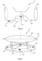
- Fig. 4 shows a wind speed sensor 111 for a flow meter according to another embodiment of the invention.
- the sensor has two rotationally symmetrical plates 401, 402, whose spacing is reduced in the middle by a bulge. At least three sensors at an angle of 120 degrees to each other, but for example four sensors 421, 422, 423 (the fourth sensor can not be seen) are arranged at an angle of 90 degrees concentric with the center of one of the plates around this bulge. It can also be arranged more pressure sensors along this circle in the outer region of the lower plate. Likewise, corresponding pressure sensors can also be arranged on the upper plate. At the center there is another pressure sensor 424, so that the differential pressure between the outside area, in which the four sensors 421, 422, 423 (the fourth can not be seen) are arranged, and the central area, in which the sensor 424 is arranged, determined can be.
- the wind speed sensor is open in an angular range of 360 degrees (ie, on all sides), so that in addition to the wind speed and the wind direction can be determined.
- the pressure sensors may also be disposed on the inclined surface 450 of the upper plate 402 or on the cut surface 430 of the lower plate 401. Also, the arrangement of other pressure sensors is possible. All pressure sensors are connected to the processor 320 (control unit), which can perform the calculation of wind speed and wind direction.
- the pressure sensors are integrated into the corresponding plate and have access to the space between the two plates, through which the wind blows.
- Fig. 5 shows a cross-sectional view of the wind sensor of Fig. 4 along the line 410.
- the taper in both the radially symmetric case and in the tube according to Fig. 3 is such that no undesirable turbulence and turbulence develop.
- Fig. 6 shows a flowchart of a method according to an embodiment of the invention.
- a level measurement is performed to determine the level of the flowing body of water.
- a flow velocity determination takes place at a certain area of the water body, for example by a Doppler measurement.
- the determination of the wind speed at the location of the flow meter takes place, and in step 604, the flow of the water is determined by taking into account the three acquired measured values.
- the steps 601 to 603 may also be performed in a different order and / or simultaneously.
- step 605 the flow rate calculated by the device is communicated to an external unit.
Landscapes
- Physics & Mathematics (AREA)
- General Physics & Mathematics (AREA)
- Engineering & Computer Science (AREA)
- Aviation & Aerospace Engineering (AREA)
- Fluid Mechanics (AREA)
- Multimedia (AREA)
- Electromagnetism (AREA)
- Acoustics & Sound (AREA)
- Indicating Or Recording The Presence, Absence, Or Direction Of Movement (AREA)
- Measuring Volume Flow (AREA)
Priority Applications (5)
| Application Number | Priority Date | Filing Date | Title |
|---|---|---|---|
| EP15202464.2A EP3185017A1 (fr) | 2015-12-23 | 2015-12-23 | Debitmetre comprenant un anemometre pour mesurer la vitesse du vent |
| EP16197571.9A EP3185018B1 (fr) | 2015-12-23 | 2016-11-07 | Débitmètre comprenant un capteur anémomètrique |
| DE202016008539.6U DE202016008539U1 (de) | 2015-12-23 | 2016-11-07 | Durchflussmessgerät mit Windgeschwindigkeitssensor |
| US15/389,026 US10495500B2 (en) | 2015-12-23 | 2016-12-22 | Flow measuring instrument comprising a wind velocity sensor |
| CN201611207074.8A CN106908108A (zh) | 2015-12-23 | 2016-12-23 | 包括风速传感器的流量测量装置 |
Applications Claiming Priority (1)
| Application Number | Priority Date | Filing Date | Title |
|---|---|---|---|
| EP15202464.2A EP3185017A1 (fr) | 2015-12-23 | 2015-12-23 | Debitmetre comprenant un anemometre pour mesurer la vitesse du vent |
Publications (1)
| Publication Number | Publication Date |
|---|---|
| EP3185017A1 true EP3185017A1 (fr) | 2017-06-28 |
Family
ID=55024014
Family Applications (2)
| Application Number | Title | Priority Date | Filing Date |
|---|---|---|---|
| EP15202464.2A Ceased EP3185017A1 (fr) | 2015-12-23 | 2015-12-23 | Debitmetre comprenant un anemometre pour mesurer la vitesse du vent |
| EP16197571.9A Active EP3185018B1 (fr) | 2015-12-23 | 2016-11-07 | Débitmètre comprenant un capteur anémomètrique |
Family Applications After (1)
| Application Number | Title | Priority Date | Filing Date |
|---|---|---|---|
| EP16197571.9A Active EP3185018B1 (fr) | 2015-12-23 | 2016-11-07 | Débitmètre comprenant un capteur anémomètrique |
Country Status (4)
| Country | Link |
|---|---|
| US (1) | US10495500B2 (fr) |
| EP (2) | EP3185017A1 (fr) |
| CN (1) | CN106908108A (fr) |
| DE (1) | DE202016008539U1 (fr) |
Cited By (1)
| Publication number | Priority date | Publication date | Assignee | Title |
|---|---|---|---|---|
| CN114545025A (zh) * | 2022-03-18 | 2022-05-27 | 南方电网数字电网研究院有限公司 | 宽量程风速及流量测量方法、装置、计算机设备、介质 |
Families Citing this family (5)
| Publication number | Priority date | Publication date | Assignee | Title |
|---|---|---|---|---|
| EP4109054A1 (fr) * | 2021-06-21 | 2022-12-28 | Flow-Tronic S.A. | Procédé et système non invasifs de mesure de la vitesse de surface d'un fluide s'écoulant dans une rivière, un canal ouvert ou une canalisation souterraine |
| CN113550927A (zh) * | 2021-09-01 | 2021-10-26 | 镇江市丹徒区粮机厂有限公司 | 一种风速可视化的工业用风机 |
| CN114324970B (zh) * | 2021-12-17 | 2023-01-10 | 华南农业大学 | 一种阵列式自适应的风向风速测量装置及方法 |
| CN114675051B (zh) * | 2022-03-08 | 2022-10-28 | 中国水利水电科学研究院 | 一种基于压差测量的河流流速监测装置、系统和方法 |
| CN115656933A (zh) * | 2022-09-19 | 2023-01-31 | 智驰华芯(无锡)传感科技有限公司 | 一种应对恶劣天气条件下的水面流速测量方法及装置 |
Citations (4)
| Publication number | Priority date | Publication date | Assignee | Title |
|---|---|---|---|---|
| JP2004219179A (ja) * | 2003-01-10 | 2004-08-05 | Public Works Research Institute | 非接触型流速計を用いた開水路流量観測方法及びその装置 |
| DE102009042111A1 (de) * | 2008-09-19 | 2010-04-01 | Hydro Vision Gmbh | Messsonde zum Bestimmen einer Strömungsgeschwindigkeit in einem offenen Gerinne und Verfahren zum Bestimmen der Position der Messsonde |
| US20100154561A1 (en) * | 2008-12-19 | 2010-06-24 | Ramon Cabrera | Integrated Multi-Beam Acoustic Doppler Discharge Measurement System |
| DE102013213345A1 (de) | 2013-07-08 | 2015-01-08 | Vega Grieshaber Kg | Universelle Messdatenerfassung in Gewässern |
Family Cites Families (9)
| Publication number | Priority date | Publication date | Assignee | Title |
|---|---|---|---|---|
| US3820714A (en) * | 1972-10-06 | 1974-06-28 | L Erickson | Water jet projector and control apparatus |
| DE2733306C2 (de) | 1977-07-20 | 1979-08-23 | Hellmut 1000 Berlin Nitsche | Gerät zur Messung der Durchflußmenge strömender Medien |
| US4261210A (en) | 1979-10-09 | 1981-04-14 | Gardner William L | Stacked wafer helical flowmeter |
| US6137439A (en) | 1998-09-08 | 2000-10-24 | Lockheed Martin Corporation | Continuous wave doppler system with suppression of ground clutter |
| US20030056584A1 (en) * | 2001-09-27 | 2003-03-27 | Park Tae-Won | Mass flow sensor and measuring apparatus |
| CN2716811Y (zh) | 2004-08-18 | 2005-08-10 | 浙江大学 | 测热型和风速计一体化流速传感器 |
| JP5178388B2 (ja) * | 2008-08-11 | 2013-04-10 | 日立オートモティブシステムズ株式会社 | 空気流量測定装置 |
| CN101598581B (zh) | 2009-07-14 | 2012-04-25 | 湖北工业大学土木工程与建筑学院 | 基于分布式光纤温度传感技术的流速测量系统及其方法 |
| US10773271B2 (en) * | 2014-06-20 | 2020-09-15 | Deere & Company | Time varying control of the operation of spray systems |
-
2015
- 2015-12-23 EP EP15202464.2A patent/EP3185017A1/fr not_active Ceased
-
2016
- 2016-11-07 DE DE202016008539.6U patent/DE202016008539U1/de active Active
- 2016-11-07 EP EP16197571.9A patent/EP3185018B1/fr active Active
- 2016-12-22 US US15/389,026 patent/US10495500B2/en active Active
- 2016-12-23 CN CN201611207074.8A patent/CN106908108A/zh active Pending
Patent Citations (4)
| Publication number | Priority date | Publication date | Assignee | Title |
|---|---|---|---|---|
| JP2004219179A (ja) * | 2003-01-10 | 2004-08-05 | Public Works Research Institute | 非接触型流速計を用いた開水路流量観測方法及びその装置 |
| DE102009042111A1 (de) * | 2008-09-19 | 2010-04-01 | Hydro Vision Gmbh | Messsonde zum Bestimmen einer Strömungsgeschwindigkeit in einem offenen Gerinne und Verfahren zum Bestimmen der Position der Messsonde |
| US20100154561A1 (en) * | 2008-12-19 | 2010-06-24 | Ramon Cabrera | Integrated Multi-Beam Acoustic Doppler Discharge Measurement System |
| DE102013213345A1 (de) | 2013-07-08 | 2015-01-08 | Vega Grieshaber Kg | Universelle Messdatenerfassung in Gewässern |
Non-Patent Citations (2)
| Title |
|---|
| ANONYMOUS: "Algorithm Determines Wind Speed and Direction From Venturi-Sensor Data Speed and direction are calculated from the spatial distribution of pressure readings", NASA TECH BRIEFS, DECEMBER 2004, 1 December 2004 (2004-12-01), pages 24, XP055251213, Retrieved from the Internet <URL:http://ntrs.nasa.gov/archive/nasa/casi.ntrs.nasa.gov/20110020451.pdf> [retrieved on 20160218] * |
| FULTON J ET AL: "Measuring real-time streamflow using emerging technologies: Radar, hydroacoustics, and the probability concept", JOURNAL OF HYDROLOGY, NORTH-HOLLAND, AMSTERDAM, NL, vol. 357, no. 1-2, 30 July 2008 (2008-07-30), pages 1 - 10, XP022796303, ISSN: 0022-1694, [retrieved on 20080414], DOI: 10.1016/J.JHYDROL.2008.03.028 * |
Cited By (1)
| Publication number | Priority date | Publication date | Assignee | Title |
|---|---|---|---|---|
| CN114545025A (zh) * | 2022-03-18 | 2022-05-27 | 南方电网数字电网研究院有限公司 | 宽量程风速及流量测量方法、装置、计算机设备、介质 |
Also Published As
| Publication number | Publication date |
|---|---|
| EP3185018A1 (fr) | 2017-06-28 |
| US10495500B2 (en) | 2019-12-03 |
| CN106908108A (zh) | 2017-06-30 |
| EP3185018B1 (fr) | 2018-08-08 |
| US20170184430A1 (en) | 2017-06-29 |
| DE202016008539U1 (de) | 2018-04-19 |
Similar Documents
| Publication | Publication Date | Title |
|---|---|---|
| EP3185018B1 (fr) | Débitmètre comprenant un capteur anémomètrique | |
| DE2640087C2 (fr) | ||
| EP2665930B1 (fr) | Procédé de détermination de l'inclinaison d'une tour | |
| DE1920699C3 (de) | Meßsonde zur Ermittlung statischer Strömungsmitteldrücke | |
| WO2006048395A1 (fr) | Dispositif de determination et/ou de controle du debit volumique et/ou massique d'un fluide | |
| EP0046965A1 (fr) | Procédé et appareil pour la détermination dynamique du débit massique independant de la densité | |
| EP3457095B1 (fr) | Capteur de niveau capacitif et procédé de mesure du niveau de remplissage d'un milieu | |
| DE112020000365B4 (de) | Verfahren zum Bestimmen einer Strömungsgeschwindigkeitsverteilung rauer Unterschicht | |
| DE102007041717A1 (de) | Verfahren und Vorrichtung zur Bestimmung der Oberflächengeschwindigkeiten und der Durchflussmenge von Flüssigkeiten in Rohrleitungen, offenen oder geschlossenen Kanälen und Gewässern | |
| EP1314985B1 (fr) | Dispositif de mesure de données aérodynamiques et système de mesure de données aérodynamiques pour des aéronefs | |
| EP0236569B1 (fr) | Procédé et dispositif de détermination de la direction relative du vent et/ou de la vitesse du vent à un point de mesure fixe ou mobile | |
| WO2016142071A1 (fr) | Anémomètre à ultrason | |
| EP2041523B1 (fr) | Dispositif de mesure servant à la mesure du débit dans un canal | |
| EP3361094A1 (fr) | Éolienne et parc éolien comprenant au moins une telle éolienne | |
| EP4022259B1 (fr) | Débitmètre à induction magnétique et procédé de fonctionnement d'un débitmètre à induction magnétique | |
| EP3088845B1 (fr) | Determination d'un itineraire selectionne par un utilisateur d'un systeme de navigation | |
| DE2619727A1 (de) | Fluidum-stroemungsmesser | |
| EP3553533B1 (fr) | Sonde de couche limite, dispositif de mesure ainsi que procédé de détermination d'un flux d'un fluide | |
| EP3748308A1 (fr) | Débitmètre à ultrasons, utilisation d'un débitmètre à ultrasons dans un organe d'arrêt et organe d'arrêt | |
| EP3748309B1 (fr) | Débitmètre à ultrasons, utilisation d'un débitmètre à ultrasons dans un organe d'arrêt et organe d'arrêt | |
| EP3211385B1 (fr) | Débitmètre à ultrasons | |
| WO2010015234A2 (fr) | Procédé et dispositif de détermination d'un débit de fluide | |
| EP4031857B1 (fr) | Système de mesure multiphase avec mise à jour de valeurs d'étalonnage, et ensemble fluidique | |
| DE102020107181B4 (de) | Vorrichtung und deren verwendung zum orten von schallquellen durch beamforming | |
| DE4443483A1 (de) | Verfahren und Vorrichtung zur Strömungsmessung an Flüssigkeiten |
Legal Events
| Date | Code | Title | Description |
|---|---|---|---|
| PUAI | Public reference made under article 153(3) epc to a published international application that has entered the european phase |
Free format text: ORIGINAL CODE: 0009012 |
|
| STAA | Information on the status of an ep patent application or granted ep patent |
Free format text: STATUS: THE APPLICATION HAS BEEN PUBLISHED |
|
| AK | Designated contracting states |
Kind code of ref document: A1 Designated state(s): AL AT BE BG CH CY CZ DE DK EE ES FI FR GB GR HR HU IE IS IT LI LT LU LV MC MK MT NL NO PL PT RO RS SE SI SK SM TR |
|
| AX | Request for extension of the european patent |
Extension state: BA ME |
|
| STAA | Information on the status of an ep patent application or granted ep patent |
Free format text: STATUS: REQUEST FOR EXAMINATION WAS MADE |
|
| 17P | Request for examination filed |
Effective date: 20170911 |
|
| RBV | Designated contracting states (corrected) |
Designated state(s): AL AT BE BG CH CY CZ DE DK EE ES FI FR GB GR HR HU IE IS IT LI LT LU LV MC MK MT NL NO PL PT RO RS SE SI SK SM TR |
|
| STAA | Information on the status of an ep patent application or granted ep patent |
Free format text: STATUS: EXAMINATION IS IN PROGRESS |
|
| 17Q | First examination report despatched |
Effective date: 20171207 |
|
| STAA | Information on the status of an ep patent application or granted ep patent |
Free format text: STATUS: THE APPLICATION HAS BEEN REFUSED |
|
| 18R | Application refused |
Effective date: 20190219 |