EP3185232A1 - Informationsverwaltungsvorrichtung, fahrzeug und informationsverwaltungsverfahren - Google Patents
Informationsverwaltungsvorrichtung, fahrzeug und informationsverwaltungsverfahren Download PDFInfo
- Publication number
- EP3185232A1 EP3185232A1 EP15833018.3A EP15833018A EP3185232A1 EP 3185232 A1 EP3185232 A1 EP 3185232A1 EP 15833018 A EP15833018 A EP 15833018A EP 3185232 A1 EP3185232 A1 EP 3185232A1
- Authority
- EP
- European Patent Office
- Prior art keywords
- information
- vehicle
- difference
- dimensional
- dimensional map
- Prior art date
- Legal status (The legal status is an assumption and is not a legal conclusion. Google has not performed a legal analysis and makes no representation as to the accuracy of the status listed.)
- Ceased
Links
Images

Classifications
-
- G—PHYSICS
- G08—SIGNALLING
- G08G—TRAFFIC CONTROL SYSTEMS
- G08G1/00—Traffic control systems for road vehicles
- G08G1/01—Detecting movement of traffic to be counted or controlled
- G08G1/0104—Measuring and analyzing of parameters relative to traffic conditions
- G08G1/0108—Measuring and analyzing of parameters relative to traffic conditions based on the source of data
- G08G1/0112—Measuring and analyzing of parameters relative to traffic conditions based on the source of data from the vehicle, e.g. floating car data [FCD]
-
- G—PHYSICS
- G05—CONTROLLING; REGULATING
- G05D—SYSTEMS FOR CONTROLLING OR REGULATING NON-ELECTRIC VARIABLES
- G05D1/00—Control of position, course, altitude or attitude of land, water, air or space vehicles, e.g. using automatic pilots
- G05D1/02—Control of position or course in two dimensions
- G05D1/021—Control of position or course in two dimensions specially adapted to land vehicles
- G05D1/0231—Control of position or course in two dimensions specially adapted to land vehicles using optical position detecting means
- G05D1/0246—Control of position or course in two dimensions specially adapted to land vehicles using optical position detecting means using a video camera in combination with image processing means
- G05D1/0248—Control of position or course in two dimensions specially adapted to land vehicles using optical position detecting means using a video camera in combination with image processing means in combination with a laser
-
- G—PHYSICS
- G01—MEASURING; TESTING
- G01B—MEASURING LENGTH, THICKNESS OR SIMILAR LINEAR DIMENSIONS; MEASURING ANGLES; MEASURING AREAS; MEASURING IRREGULARITIES OF SURFACES OR CONTOURS
- G01B11/00—Measuring arrangements characterised by the use of optical techniques
- G01B11/24—Measuring arrangements characterised by the use of optical techniques for measuring contours or curvatures
- G01B11/25—Measuring arrangements characterised by the use of optical techniques for measuring contours or curvatures by projecting a pattern, e.g. one or more lines, moiré fringes on the object
- G01B11/2518—Projection by scanning of the object
-
- G—PHYSICS
- G01—MEASURING; TESTING
- G01C—MEASURING DISTANCES, LEVELS OR BEARINGS; SURVEYING; NAVIGATION; GYROSCOPIC INSTRUMENTS; PHOTOGRAMMETRY OR VIDEOGRAMMETRY
- G01C21/00—Navigation; Navigational instruments not provided for in groups G01C1/00 - G01C19/00
- G01C21/26—Navigation; Navigational instruments not provided for in groups G01C1/00 - G01C19/00 specially adapted for navigation in a road network
- G01C21/34—Route searching; Route guidance
- G01C21/36—Input/output arrangements for on-board computers
- G01C21/3602—Input other than that of destination using image analysis, e.g. detection of road signs, lanes, buildings, real preceding vehicles using a camera
-
- G—PHYSICS
- G01—MEASURING; TESTING
- G01C—MEASURING DISTANCES, LEVELS OR BEARINGS; SURVEYING; NAVIGATION; GYROSCOPIC INSTRUMENTS; PHOTOGRAMMETRY OR VIDEOGRAMMETRY
- G01C21/00—Navigation; Navigational instruments not provided for in groups G01C1/00 - G01C19/00
- G01C21/26—Navigation; Navigational instruments not provided for in groups G01C1/00 - G01C19/00 specially adapted for navigation in a road network
- G01C21/34—Route searching; Route guidance
- G01C21/36—Input/output arrangements for on-board computers
- G01C21/3626—Details of the output of route guidance instructions
- G01C21/3635—Guidance using 3D or perspective road maps
- G01C21/3638—Guidance using 3D or perspective road maps including 3D objects and buildings
-
- G—PHYSICS
- G01—MEASURING; TESTING
- G01C—MEASURING DISTANCES, LEVELS OR BEARINGS; SURVEYING; NAVIGATION; GYROSCOPIC INSTRUMENTS; PHOTOGRAMMETRY OR VIDEOGRAMMETRY
- G01C21/00—Navigation; Navigational instruments not provided for in groups G01C1/00 - G01C19/00
- G01C21/26—Navigation; Navigational instruments not provided for in groups G01C1/00 - G01C19/00 specially adapted for navigation in a road network
- G01C21/34—Route searching; Route guidance
- G01C21/36—Input/output arrangements for on-board computers
- G01C21/3626—Details of the output of route guidance instructions
- G01C21/3647—Guidance involving output of stored or live camera images or video streams
-
- G—PHYSICS
- G01—MEASURING; TESTING
- G01C—MEASURING DISTANCES, LEVELS OR BEARINGS; SURVEYING; NAVIGATION; GYROSCOPIC INSTRUMENTS; PHOTOGRAMMETRY OR VIDEOGRAMMETRY
- G01C21/00—Navigation; Navigational instruments not provided for in groups G01C1/00 - G01C19/00
- G01C21/38—Electronic maps specially adapted for navigation; Updating thereof
- G01C21/3804—Creation or updating of map data
- G01C21/3833—Creation or updating of map data characterised by the source of data
- G01C21/3848—Data obtained from both position sensors and additional sensors
-
- G—PHYSICS
- G01—MEASURING; TESTING
- G01C—MEASURING DISTANCES, LEVELS OR BEARINGS; SURVEYING; NAVIGATION; GYROSCOPIC INSTRUMENTS; PHOTOGRAMMETRY OR VIDEOGRAMMETRY
- G01C21/00—Navigation; Navigational instruments not provided for in groups G01C1/00 - G01C19/00
- G01C21/38—Electronic maps specially adapted for navigation; Updating thereof
- G01C21/3804—Creation or updating of map data
- G01C21/3859—Differential updating map data
-
- G—PHYSICS
- G01—MEASURING; TESTING
- G01C—MEASURING DISTANCES, LEVELS OR BEARINGS; SURVEYING; NAVIGATION; GYROSCOPIC INSTRUMENTS; PHOTOGRAMMETRY OR VIDEOGRAMMETRY
- G01C21/00—Navigation; Navigational instruments not provided for in groups G01C1/00 - G01C19/00
- G01C21/38—Electronic maps specially adapted for navigation; Updating thereof
- G01C21/3863—Structures of map data
- G01C21/3867—Geometry of map features, e.g. shape points, polygons or for simplified maps
-
- G—PHYSICS
- G01—MEASURING; TESTING
- G01S—RADIO DIRECTION-FINDING; RADIO NAVIGATION; DETERMINING DISTANCE OR VELOCITY BY USE OF RADIO WAVES; LOCATING OR PRESENCE-DETECTING BY USE OF THE REFLECTION OR RERADIATION OF RADIO WAVES; ANALOGOUS ARRANGEMENTS USING OTHER WAVES
- G01S17/00—Systems using the reflection or reradiation of electromagnetic waves other than radio waves, e.g. lidar systems
- G01S17/02—Systems using the reflection of electromagnetic waves other than radio waves
- G01S17/06—Systems determining position data of a target
- G01S17/08—Systems determining position data of a target for measuring distance only
- G01S17/10—Systems determining position data of a target for measuring distance only using transmission of interrupted, pulse-modulated waves
-
- G—PHYSICS
- G01—MEASURING; TESTING
- G01S—RADIO DIRECTION-FINDING; RADIO NAVIGATION; DETERMINING DISTANCE OR VELOCITY BY USE OF RADIO WAVES; LOCATING OR PRESENCE-DETECTING BY USE OF THE REFLECTION OR RERADIATION OF RADIO WAVES; ANALOGOUS ARRANGEMENTS USING OTHER WAVES
- G01S17/00—Systems using the reflection or reradiation of electromagnetic waves other than radio waves, e.g. lidar systems
- G01S17/86—Combinations of lidar systems with systems other than lidar, radar or sonar, e.g. with direction finders
-
- G—PHYSICS
- G01—MEASURING; TESTING
- G01S—RADIO DIRECTION-FINDING; RADIO NAVIGATION; DETERMINING DISTANCE OR VELOCITY BY USE OF RADIO WAVES; LOCATING OR PRESENCE-DETECTING BY USE OF THE REFLECTION OR RERADIATION OF RADIO WAVES; ANALOGOUS ARRANGEMENTS USING OTHER WAVES
- G01S17/00—Systems using the reflection or reradiation of electromagnetic waves other than radio waves, e.g. lidar systems
- G01S17/88—Lidar systems specially adapted for specific applications
- G01S17/89—Lidar systems specially adapted for specific applications for mapping or imaging
-
- G—PHYSICS
- G01—MEASURING; TESTING
- G01S—RADIO DIRECTION-FINDING; RADIO NAVIGATION; DETERMINING DISTANCE OR VELOCITY BY USE OF RADIO WAVES; LOCATING OR PRESENCE-DETECTING BY USE OF THE REFLECTION OR RERADIATION OF RADIO WAVES; ANALOGOUS ARRANGEMENTS USING OTHER WAVES
- G01S17/00—Systems using the reflection or reradiation of electromagnetic waves other than radio waves, e.g. lidar systems
- G01S17/88—Lidar systems specially adapted for specific applications
- G01S17/93—Lidar systems specially adapted for specific applications for anti-collision purposes
- G01S17/931—Lidar systems specially adapted for specific applications for anti-collision purposes of land vehicles
-
- G—PHYSICS
- G01—MEASURING; TESTING
- G01S—RADIO DIRECTION-FINDING; RADIO NAVIGATION; DETERMINING DISTANCE OR VELOCITY BY USE OF RADIO WAVES; LOCATING OR PRESENCE-DETECTING BY USE OF THE REFLECTION OR RERADIATION OF RADIO WAVES; ANALOGOUS ARRANGEMENTS USING OTHER WAVES
- G01S7/00—Details of systems according to groups G01S13/00, G01S15/00, G01S17/00
- G01S7/003—Transmission of data between radar, sonar or lidar systems and remote stations
-
- G—PHYSICS
- G01—MEASURING; TESTING
- G01S—RADIO DIRECTION-FINDING; RADIO NAVIGATION; DETERMINING DISTANCE OR VELOCITY BY USE OF RADIO WAVES; LOCATING OR PRESENCE-DETECTING BY USE OF THE REFLECTION OR RERADIATION OF RADIO WAVES; ANALOGOUS ARRANGEMENTS USING OTHER WAVES
- G01S7/00—Details of systems according to groups G01S13/00, G01S15/00, G01S17/00
- G01S7/48—Details of systems according to groups G01S13/00, G01S15/00, G01S17/00 of systems according to group G01S17/00
- G01S7/4808—Evaluating distance, position or velocity data
-
- G—PHYSICS
- G08—SIGNALLING
- G08G—TRAFFIC CONTROL SYSTEMS
- G08G1/00—Traffic control systems for road vehicles
- G08G1/01—Detecting movement of traffic to be counted or controlled
- G08G1/0104—Measuring and analyzing of parameters relative to traffic conditions
- G08G1/0137—Measuring and analyzing of parameters relative to traffic conditions for specific applications
-
- G—PHYSICS
- G08—SIGNALLING
- G08G—TRAFFIC CONTROL SYSTEMS
- G08G1/00—Traffic control systems for road vehicles
- G08G1/09—Arrangements for giving variable traffic instructions
- G08G1/0962—Arrangements for giving variable traffic instructions having an indicator mounted inside the vehicle, e.g. giving voice messages
- G08G1/0968—Systems involving transmission of navigation instructions to the vehicle
- G08G1/0969—Systems involving transmission of navigation instructions to the vehicle having a display in the form of a map
Definitions
- the present invention relates to an information management device, a vehicle, and an information management method which use three-dimensional map information.
- the accurate road information is three-dimensional information including, for example, not only road widths, lanes, detailed position information of signs, and the like but information of inclinations of roads, unevenness of roads, unevenness of shoulders, and the like.
- driving instruction information is generated with which a vehicle automatically travel to a destination.
- the vehicle is able to automatically travel to a destination by adding, on the basis of the driving instruction information, real-time three-dimensional information in the periphery of the vehicle detected by various sensors mounted on the vehicle (for example, PTL 1).
- a surveying vehicle In order to generate three-dimensional map information, a surveying vehicle is used on which various sensors such as a highly accurate camera, a laser radar, and the like are mounted.
- the various sensors are disposed on, for example, a part above a roof of the vehicle (for example, PTL 2).
- information management device when it is determined that a road shape recognized on the basis of an image captured by a vehicle-mounted camera is different from a road shape based on stored road map data, information is transmitted to a management server, where the information includes a spot at which the respective pieces of road information are different and the information further includes the captured image at the spot.
- the management server accumulates information about a spot at which a road shape in road map data is different from an actual road shape based on an image captured by a vehicle-mounted camera. Because information about the spot whose road map data needs to be updated is obtained at a time when the road map data is updated, it is possible to reduce time and effort for updating (for example, PTL 3).
- the present invention provides an information management device in which it is possible to correct a difference in measurement conditions between a surveying vehicle for generating three-dimensional map information and a vehicle which uses the three-dimensional map information.
- An information management device includes a difference extractor and a determination unit.
- the difference extractor extracts as difference information a difference between vehicle peripheral three-dimensional information detected by a vehicle and three-dimensional map information.
- the determination unit determines whether the extracted difference information is a difference inherent to the vehicle.
- An information management method includes a difference extraction step in which the difference between vehicle peripheral three-dimensional information detected by a vehicle and three-dimensional map information is extracted as difference information, and a determination step in which it is determined whether the difference information is a difference inherent to the vehicle.
- the present invention determines that the difference information is the difference inherent to the vehicle, the present invention generates correction information on the basis of the difference information. By this operation, it is possible to correct the difference in the measurement conditions between the surveying vehicle for generating three-dimensional map information and the vehicle which uses the three-dimensional map information.
- Various sensors mounted on a vehicle which actually performs self-driving are different from various sensors mounted on a surveying vehicle which generates three-dimensional map information.
- the various sensors mounted on the surveying vehicle are disposed on a part higher than the roof of the vehicle; however, the various sensors mounted on the vehicle which performs self-driving are disposed in the periphery of the bumper in some cases.
- the positions at which the various sensors are disposed are different as described above, there is a possibility that the same bump on a road is detected to have different heights, for example.
- the height of an object detected by a vehicle is different from the height of an object included in three-dimensional map information, for example.
- Accuracies or performances of various sensors include, for example, a resolution of sensor and a searching range of sensor.
- a management server accumulates information about a spot at which the road shape in road map data is different from the road shape based on a vehicle-mounted camera image.
- the road shape in the road map data is determined to be different from the road shape based on the vehicle-mounted camera image, there may be no difference created in the actual road shape but the difference may be a difference due to the difference in the measurement conditions.
- difference may be determined to exist, and the map information may be updated.
- the three-dimensional map information needs to be accurate; however, if the difference in the measurement conditions is not corrected, the three-dimensional map information cannot be accurately updated, and as a result, there can be a possibility that safe self-driving is not achieved.
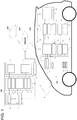
- An information management device 1 of the present exemplary embodiment is configured with self-driving support server 400 and vehicle-mounted device 100.
- Vehicle-mounted device 100 is a device mounted on vehicle 200
- self-driving support server 400 is a computer installed outside vehicle 200.
- Vehicle-mounted device 100 and self-driving support server 400 can communicate with each other through network 300.
- Self-driving support server 400 can mutually communicate with vehicles other than vehicle 200 such as another vehicle 500 in FIG. 1 .
- network 300 wireless communication is typically used; however, wired communication can be applied, for example, when communication is performed through a charging cable, which is a wire, during charge of an electric vehicle or the like.
- Vehicle-mounted device 100 includes detector 110, vehicle-side communication unit 120, vehicle-side controller 130, vehicle-side information storage 140, GPS receiver 150, notification unit 160, operation unit 170, and drive unit 180.
- Detector 110 detects three-dimensional information in the periphery of vehicle 200 (hereinafter, referred to as vehicle peripheral three-dimensional information). Detector 110 includes camera 111 and laser radar 112.
- Camera 111 is configured with, for example, a plurality of cameras and can detect vehicle peripheral three-dimensional information from the difference between two-dimensional images taken by the respective cameras. Further, laser radar 112 sends laser pulses to the periphery of vehicle 200 and detects vehicle peripheral three-dimensional information by measuring distances to objects in the periphery of the vehicle on the basis of return time of reflected light. It is also possible to scan with a laser beam to detect the shape of an object in the periphery of the vehicle. Detector 110 may include other sensors than the above sensors.
- Vehicle-side communication unit 120 transmits and receives various pieces of information to and from self-driving support server 400 through network 300. Vehicle-side communication unit 120 performs communication through, for example, wireless communication using a mobile telephone line. Vehicle-side communication unit 120 is controlled by vehicle-side controller 130.
- Vehicle-side controller 130 is a processing unit including, for example, a CPU (central processing unit) and a RAM (Random Access Memory) and is configured to transmit and receive information and to control the respective units.
- Vehicle-side controller 130 is connected to detector 110, vehicle-side communication unit 120, vehicle-side information storage 140, GPS receiver 150, notification unit 160, operation unit 170, and drive unit 180.
- vehicle-side controller 130 is configured with drive controller 131, vehicle peripheral three-dimensional information extractor 132, difference extractor 133, determination unit 134, and vehicle peripheral three-dimensional information corrector 135. A function of each unit equipped on vehicle-side controller 130 will be described in detail later with reference to FIG. 2 .
- Vehicle-side information storage 140 is configured with a device such as a hard disk or a RAM (Random Access Memory) which can store information. Various pieces of information can be written in and read out to and from vehicle-side information storage 140 being controlled by vehicle-side controller 130.
- a device such as a hard disk or a RAM (Random Access Memory) which can store information.
- Various pieces of information can be written in and read out to and from vehicle-side information storage 140 being controlled by vehicle-side controller 130.
- vehicle-side information storage 140 and vehicle-side communication unit 120 can also mutually transmit and receive information.
- vehicle-side information storage 140 includes vehicle's inherent correction information storage 141, three-dimensional map information storage 142, difference information storage 143, driving instruction information storage 144, and vehicle peripheral three-dimensional information storage 145.
- Vehicle-side information storage 140 may be configured with a single storage device or may be configured with a plurality of storage devices. Various pieces of information to be stored in vehicle-side information storage 140 will be described later in detail with reference to FIG. 2 .
- GPS receiver 150 receives signals from a plurality of GPS (Global Positioning System) satellites and acquires position information indicating the current position of vehicle 200 by demodulating the received signals. GPS receiver 150 outputs the acquired position information to vehicle-side controller 130.
- GPS Global Positioning System
- Notification unit 160 is a display, a speaker, or an actuator, and notifies a driver of various pieces of information with at least one of sound, light, and vibration. Notification unit 160 is controlled by vehicle-side controller 130.
- Operation unit 170 is a device such as a switch or a touch panel which can be operated by a user.
- a driver as a user can specify execution of various settings about self-driving by operating operation unit 170.
- self-driving means a function which automatically drives a vehicle to a destination and means whole of a function which automatically moves a vehicle by means other than a driving operation of a driver.
- Drive unit 180 generates driving force to turn wheels of the vehicle.
- Drive unit 180 is, for example, an electric motor or an engine of various types.
- drive unit 180 is controlled depending on an acceleration/deceleration operation of a driver.
- drive unit 180 is controlled directly by drive controller 131.
- Self-driving support server 400 is a computer having a CPU (Central Processing Unit) functioning as a processing unit, a RAM (Random Access Memory) and a hard disk functioning as server-side information storage 410, a communication device, a display or a printer functioning as an information output unit, an input device to input an operation instruction of an operator, and other components.
- CPU Central Processing Unit
- RAM Random Access Memory
- hard disk functioning as server-side information storage 410
- communication device a display or a printer functioning as an information output unit
- an input device to input an operation instruction of an operator and other components.
- Self-driving support server 400 is configured to include server-side information storage 410, server-side controller 420, and server-side communication unit 430. Next, a description will be given on detailed configurations of server-side information storage 410, server-side controller 420, and server-side communication unit 430.
- Server-side information storage 410 is configured with a device such as a hard disk or a RAM (Random Access Memory) which can store information. Various pieces of information can be written in and read out to and from server-side information storage 410 being controlled by server-side controller 420.
- a device such as a hard disk or a RAM (Random Access Memory) which can store information.
- RAM Random Access Memory
- server-side information storage 410 and server-side communication unit 430 can also mutually transmit and receive information.
- server-side information storage 410 includes difference information storage 411, vehicle's inherent correction information storage 412, driving instruction information storage 413, three-dimensional map information storage 414, and destination information storage 415.
- Server-side information storage 410 may be configured with a single storage device or may be configured with a plurality of storage devices. The various pieces of information to be stored in server-side information storage 410 will be described later in detail with reference to FIG. 2 .
- Server-side controller 420 is a processing unit including, for example, a CPU (Central Processing Unit) and RAM (Random Access Memory) and is configured to transmit and receive information and to control the respective units.
- a CPU Central Processing Unit
- RAM Random Access Memory
- server-side controller 420 is configured with vehicle's inherent correction information generator 421, collection unit 422, driving instruction information generator 423, and three-dimensional map information update unit 424. Functions of the respective units of server-side controller 420 will be described later in detail with reference to FIG. 2 .
- Server-side communication unit 430 transmits and receives various pieces of information to and from vehicle 200 through network 300.
- Server-side communication unit 430 performs communication in a similar way to vehicle-side communication unit 120 through, for example, wireless communication using a mobile telephone line.
- Server-side communication unit 430 is controlled by server-side controller 420.
- Server-side communication unit 430 can also communicate with another vehicle (for example, vehicle 500) other than vehicle 200.
- FIG. 2 is a flowchart showing an operation example of the vehicle-mounted device and the self-driving support server according to the present exemplary embodiment. Specifically, the process of FIG. 2 is performed by vehicle-side controller 130 and server-side controller 420. Steps S101 to S107 represent a processing operation of vehicle-side controller 130. Further, steps S201 to S206 represent a processing operation of server-side controller 420.
- vehicle-side controller 130 downloads three-dimensional map information and vehicle's inherent correction information (step S101).
- server-side controller 420 If receiving an instruction of download, server-side controller 420 performs control such that three-dimensional map information stored in three-dimensional map information storage 414 and vehicle's inherent correction information stored in vehicle's inherent correction information storage 412 are sent from server-side communication unit 430 (step S201).
- the three-dimensional map information received by vehicle-mounted device 100 is stored in three-dimensional map information storage 142. Further, the vehicle's inherent correction information received by vehicle-mounted device 100 is stored in vehicle's inherent correction information storage 141.
- the three-dimensional map information stored in three-dimensional map information storage 414 is information generated on the basis of the result of measurement conducted by a surveying vehicle exclusive for generating three-dimensional map information.
- the three-dimensional map information is information corresponding to position information.
- the three-dimensional map information includes as accurate road information three-dimensional information including, for example, not only road widths, lanes, detailed position information of signs, and the like but also information of inclinations of roads, unevenness of roads, unevenness of shoulders, and the like. The vehicle's inherent correction information will be described later.
- vehicle peripheral three-dimensional information extractor 132 acquires vehicle peripheral three-dimensional information, which is three-dimensional information in the periphery of vehicle 200 at the point of time, on the basis of a detection result of detector 110 (step S102).
- the acquired vehicle peripheral three-dimensional information is stored in vehicle peripheral three-dimensional information storage 145.
- the vehicle peripheral three-dimensional information is stored in vehicle peripheral three-dimensional information storage 145, in association with a current position of vehicle 200 detected by GPS receiver 150.
- vehicle peripheral three-dimensional information corrector 135 reads out the vehicle peripheral three-dimensional information stored in vehicle peripheral three-dimensional information storage 145, corrects the read-out information by using the vehicle's inherent correction information stored in vehicle's inherent correction information storage 141, and then stores again the corrected information in vehicle peripheral three-dimensional information storage 145 (step S103). This process will be described later in detail.
- difference extractor 133 extracts as difference information the difference between the vehicle peripheral three-dimensional information detected by vehicle 200 and the three-dimensional map information (step S104).
- the difference here is, for example, an object which does not exist in the three-dimensional map information but is included in the vehicle peripheral three-dimensional information. Further, the difference is, in some cases, based on the difference in measurement conditions between the surveying vehicle and the vehicle using three-dimensional map information.
- the extracted difference information is stored in difference information storage 143.
- Difference extractor 133 extracts the difference information by using the three-dimensional map information corresponding to the position information of vehicle 200 at the time when vehicle 200 detected the vehicle peripheral three-dimensional information. By this operation, comparison can be made between the information for the same position.
- step S104 determination unit 134 determines whether the difference information is a difference inherent to vehicle 200 (step S105).
- the difference inherent to vehicle 200 to be determined by determination unit 134 is a difference based on at least one of a position at which detector 110 is fixed for vehicle 200 to detect vehicle peripheral three-dimensional information, accuracy of detector 110, and performance of detector 110.
- the result of this determination is stored, as a part of difference information, in difference information storage 143 in association with the extracted difference information.
- Vehicle-side controller 130 transmits the difference information stored in difference information storage 143 to self-driving support server 400. If receiving the difference information (step S202: YES), server-side controller 420 stores the received difference information in difference information storage 411. If server-side controller 420 does not receive the difference information (step S202: NO), server-side controller 420 performs step S202 again.
- vehicle's inherent correction information generator 421 If the received difference information is the information which is determined to be the difference inherent to vehicle 200 by determination unit 134 (step S203: YES), vehicle's inherent correction information generator 421 generates, on the basis of the difference information stored in difference information storage 411, vehicle's inherent correction information with which the vehicle peripheral three-dimensional information detected by vehicle 200 is corrected (step S204).
- vehicle's inherent correction information generated by vehicle's inherent correction information generator 421 is stored in vehicle's inherent correction information storage 412.
- the vehicle's inherent correction information is represented by, for example, a predetermined coefficient, a predetermined length, or a degree of priority. For example, if it is found through a statistical process that the vehicle peripheral three-dimensional information is different from the three-dimensional map information at a constant ratio, vehicle's inherent correction information generator 421 generates vehicle's inherent correction information so that the vehicle peripheral three-dimensional information is multiplied by a predetermined coefficient. If the vehicle peripheral three-dimensional information is different by a constant length, it is also possible for vehicle's inherent correction information generator 421 to generate vehicle's inherent correction information so that the vehicle peripheral three-dimensional information is increased or decreased by a predetermined length.
- vehicle peripheral three-dimensional information corrector 135 corrects the vehicle peripheral three-dimensional information on the basis of the vehicle's inherent correction information.
- the difference extracted by difference extractor 133 becomes closer to the difference other than the difference due to the difference in measurement conditions between the surveying vehicle and vehicle 200, in other words, becomes closer to the real difference of the three-dimensional information.
- driving instruction information generator 423 generates driving instruction information for vehicle 200 to perform self-driving, on the basis of the three-dimensional map information stored in three-dimensional map information storage 414 and destination information stored in destination information storage 415.
- the destination information is information including the position information of a destination to which vehicle 200 is headed, and the destination information is previously received from vehicle 200 and is then stored.
- driving instruction information generator 423 calculates a detailed lane position, a speed, acceleration, and the like to generate the driving instruction information for vehicle 200 to automatically travel to the destination.
- the calculated driving instruction information is stored in driving instruction information storage 413 (step S205).
- Server-side controller 420 transmits the driving instruction information and the vehicle's inherent correction information to vehicle 200 (step S206). If vehicle-side controller 130 receives the driving instruction information and the vehicle's inherent correction information (step S106: YES), vehicle-side controller 130 stores the driving instruction information in driving instruction information storage 144 and the vehicle's inherent correction information in vehicle's inherent correction information storage 141. If vehicle-side controller 130 does not receive the driving instruction information (step S106: NO), vehicle-side controller 130 performs step S106 again.
- step S106 If the driving instruction information and the vehicle's inherent correction information are received (step S106: YES), drive controller 131 controls vehicle 200 on the basis of the driving instruction information stored in driving instruction information storage 144 (step S107). Specifically, drive controller 131 performs control drive unit 180 so that the vehicle can automatically drives, on the basis of the driving instruction information corresponding to the position information acquired by GPS receiver 150. While performing self-driving, drive controller 131 notifies from notification unit 160 that self-driving is being performed.
- step S108 If a self-driving termination condition is satisfied (step S108: YES), drive controller 131 finishes the process (END in FIG. 2 ).
- the self-driving termination condition is an occasion that vehicle 200 has reached the destination or some event has happened to interrupt self-driving.
- step S108 If the self-driving termination condition is not satisfied (step S108: NO), vehicle-side controller 130 returns the process to step S101 while continuing to perform self-driving.
- step S202 if the received difference information is the information which is determined not to be the difference inherent to vehicle 200 (step S203: NO), collection unit 422 collects the concerned data.
- Three-dimensional map information update unit 424 updates the three-dimensional map information stored in three-dimensional map information storage 414, on the basis of the difference information collected by collection unit 422 (step S207).
- the information which is determined not to be the difference inherent to vehicle 200 indicates that the three-dimensional information of the road on which vehicle 200 is running is different from the three-dimensional map information stored in three-dimensional map information storage 414.
- the difference information transmitted from vehicle 200 is extracted after the vehicle peripheral three-dimensional information is corrected in the process of above-mentioned step S103. Therefore, the difference information collected by collection unit 422 is closer to the real difference.
- Three-dimensional map information update unit 424 can update the three-dimensional map information on the basis of not only the information of only one vehicle but also, for example, the difference information transmitted from information of a plurality of vehicles such as the information transmitted from another vehicle 500. By this operation, the three-dimensional map information can be updated more accurately.
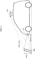
- FIG. 3 is a diagram illustrating the difference in measurement conditions between the surveying vehicle and the vehicle using three-dimensional map information.
- Surveying vehicle laser radar 700 is a radar mounted on a surveying vehicle, which is an exclusive vehicle for generating three-dimensional map information.
- laser radar 112 is a radar mounted on vehicle 200, which is a vehicle using three-dimensional map information.
- the description is made with reference to the diagram in which laser radar 112 and surveying vehicle laser radar 700 are mounted on the same vehicle; however, laser radar 112 and surveying vehicle laser radar 700 are actually mounted on different vehicles.
- Surveying vehicle laser radar 700 is disposed at a part higher than the roof of the vehicle. The reason why vehicle laser radar 700 is disposed at this position is because all of the periphery of the vehicle can be searched from this position. On the other hand, laser radar 112 is disposed in the vicinity of a front bumper of the vehicle.
- obstacle 600 is in front of the vehicle, for example.
- obstacle 600 is assumed to have a height of H vertically above the ground.
- the laser radar measures a distance to an object from a time between sending a laser pulse and returning of the reflected wave. Therefore, if the angle of obstacle 600 with respect to detection area A is different, the viewed height of the object is detected to be different.
- the mounting position of the laser radar is different, the same bump on a road is detected to have a different height in some cases, for example.
- the difference is created depending on not only the difference in mounting position but also the difference in accuracy or performance of various sensors.
- the three-dimensional map information is updated, without correcting these differences, by using the difference information between the vehicle peripheral three-dimensional information detected by the vehicle and the three-dimensional map information, the three-dimensional map information may be inaccurate.
- the three-dimensional map information needs to be accurate, and if the three-dimensional map information is not updated accurately, there may be a possibility that safe self-driving cannot be achieved.
- the functions of vehicle-side controller 130 and the functions of server-side controller 420 are interchangeable.
- the process performed by determination unit 134 may be performed by server-side controller 420.
- the process performed by vehicle's inherent correction information generator 421 may be performed by vehicle-side controller 130.
- the function may be appropriately shared depending on a processing load, a communication speed, and the like.
- steps S102 to S105 and S202 to S203 for generating the vehicle's inherent correction information is performed during a self-driving mode; however, the process may be performed during a normal driving in which driving is performed by an operation of a driver. With this arrangement, also during normal driving, it is possible to correct the difference in measurement conditions between the surveying vehicle and the vehicle using three-dimensional map information.
- the information management device of the present exemplary embodiment If difference information is determined to be a difference inherent to a vehicle, the information management device of the present exemplary embodiment generates correction information on the basis of the difference information.
- This arrangement provides an advantageous effect that it is possible for the present invention to correct the difference in measurement conditions between a surveying vehicle for generating three-dimensional map information and a vehicle using the three-dimensional map information.
- the present invention is preferable for an information management device and the like which use three-dimensional map information.
Landscapes
- Engineering & Computer Science (AREA)
- Remote Sensing (AREA)
- Radar, Positioning & Navigation (AREA)
- Physics & Mathematics (AREA)
- General Physics & Mathematics (AREA)
- Automation & Control Theory (AREA)
- Computer Networks & Wireless Communication (AREA)
- Electromagnetism (AREA)
- Computer Vision & Pattern Recognition (AREA)
- Multimedia (AREA)
- Analytical Chemistry (AREA)
- Geometry (AREA)
- Chemical & Material Sciences (AREA)
- Aviation & Aerospace Engineering (AREA)
- Optics & Photonics (AREA)
- Traffic Control Systems (AREA)
- Navigation (AREA)
- Instructional Devices (AREA)
- Business, Economics & Management (AREA)
- Artificial Intelligence (AREA)
- Evolutionary Computation (AREA)
- Game Theory and Decision Science (AREA)
- Medical Informatics (AREA)
- Health & Medical Sciences (AREA)
- Length Measuring Devices With Unspecified Measuring Means (AREA)
Applications Claiming Priority (2)
| Application Number | Priority Date | Filing Date | Title |
|---|---|---|---|
| JP2014168154A JP6322812B2 (ja) | 2014-08-21 | 2014-08-21 | 情報管理装置、車両、および、情報管理方法 |
| PCT/JP2015/002855 WO2016027394A1 (ja) | 2014-08-21 | 2015-06-08 | 情報管理装置、車両、および、情報管理方法 |
Publications (2)
| Publication Number | Publication Date |
|---|---|
| EP3185232A1 true EP3185232A1 (de) | 2017-06-28 |
| EP3185232A4 EP3185232A4 (de) | 2017-08-30 |
Family
ID=55350370
Family Applications (1)
| Application Number | Title | Priority Date | Filing Date |
|---|---|---|---|
| EP15833018.3A Ceased EP3185232A4 (de) | 2014-08-21 | 2015-06-08 | Informationsverwaltungsvorrichtung, fahrzeug und informationsverwaltungsverfahren |
Country Status (5)
| Country | Link |
|---|---|
| US (1) | US10353397B2 (de) |
| EP (1) | EP3185232A4 (de) |
| JP (1) | JP6322812B2 (de) |
| CN (1) | CN106575475B (de) |
| WO (1) | WO2016027394A1 (de) |
Families Citing this family (16)
| Publication number | Priority date | Publication date | Assignee | Title |
|---|---|---|---|---|
| US11408740B2 (en) | 2016-05-30 | 2022-08-09 | Mitsubishi Electric Corporation | Map data update apparatus, map data update method, and computer readable medium |
| CN106355878B (zh) * | 2016-09-26 | 2019-11-08 | 北京东土科技股份有限公司 | 基于智能交通云控制系统的协同控制方法及装置 |
| US10528055B2 (en) * | 2016-11-03 | 2020-01-07 | Ford Global Technologies, Llc | Road sign recognition |
| US10823574B2 (en) * | 2017-06-01 | 2020-11-03 | Panasonic Intellectual Property Corporation Of America | Communication method, roadside unit, and communication system |
| WO2018225596A1 (ja) * | 2017-06-07 | 2018-12-13 | パイオニア株式会社 | 情報処理装置 |
| EP3660455B1 (de) * | 2017-07-27 | 2023-12-20 | Nissan Motor Co., Ltd. | Fahrassistenzverfahren und fahrassistenzvorrichtung |
| EP3460406B1 (de) * | 2017-08-28 | 2024-04-03 | Panasonic Intellectual Property Corporation of America | Informationsverarbeitungsvorrichtung, fahrzeug, informationsverarbeitungsverfahren, betriebssteuerungsverfahren und kartenaktualisierungsverfahren |
| CN118050012A (zh) * | 2017-09-29 | 2024-05-17 | 松下电器(美国)知识产权公司 | 客户端装置以及由客户端装置执行的方法 |
| CN108225348B (zh) * | 2017-12-29 | 2021-08-24 | 百度在线网络技术(北京)有限公司 | 地图创建以及运动实体定位的方法和装置 |
| CN111936819B (zh) * | 2018-02-02 | 2024-11-15 | 松下电器(美国)知识产权公司 | 信息发送方法及客户端装置 |
| KR102862276B1 (ko) | 2018-07-11 | 2025-10-23 | 암페르 에스.아.에스. | 주행 환경 정보의 생성 방법, 운전 제어 방법, 주행 환경 정보 생성 장치 |
| US20210309231A1 (en) * | 2018-07-11 | 2021-10-07 | Nissan Motor Co., Ltd. | Driving Environment Information Generation Method, Driving Control Method, Driving Environment Information Generation Device |
| US11474244B2 (en) * | 2019-04-16 | 2022-10-18 | GM Global Technology Operations LLC | System and method of controlling operation of a device having an optical sensor |
| JP7716712B2 (ja) * | 2020-01-10 | 2025-08-01 | パナソニックIpマネジメント株式会社 | 三次元モデル生成方法、情報処理装置およびプログラム |
| US20220146277A1 (en) * | 2020-11-09 | 2022-05-12 | Argo AI, LLC | Architecture for map change detection in autonomous vehicles |
| WO2023214510A1 (ja) * | 2022-05-02 | 2023-11-09 | ソニーセミコンダクタソリューションズ株式会社 | 情報処理装置、情報処理システム及び情報処理方法 |
Family Cites Families (21)
| Publication number | Priority date | Publication date | Assignee | Title |
|---|---|---|---|---|
| US5359529A (en) * | 1992-05-15 | 1994-10-25 | Zexel Corporation | Route guidance on/off-route state filter |
| JP2964402B1 (ja) | 1998-08-28 | 1999-10-18 | 株式会社ゼンリン | 三次元地図データベースの作成方法及び装置 |
| JP2000338865A (ja) * | 1999-05-26 | 2000-12-08 | Komatsu Engineering Kk | デジタル道路地図のデータ収集装置 |
| US7195250B2 (en) * | 2000-03-27 | 2007-03-27 | Bose Corporation | Surface vehicle vertical trajectory planning |
| US20040046335A1 (en) * | 2000-03-27 | 2004-03-11 | Knox Lawrence D. | Surface vehicle vertical trajectory planning |
| JP2002341757A (ja) * | 2001-05-17 | 2002-11-29 | Jekku:Kk | 地図作成システム及び記録媒体 |
| WO2003001241A1 (de) * | 2001-06-15 | 2003-01-03 | Ibeo Automobile Sensor Gmbh | Korrekturverfahren für daten mehrerer optoelektronischer sensoren |
| JP2004354236A (ja) * | 2003-05-29 | 2004-12-16 | Olympus Corp | ステレオカメラ支持装置およびステレオカメラ支持方法ならびにステレオカメラシステム |
| JP2007206099A (ja) * | 2006-01-30 | 2007-08-16 | Mobile Mapping Kk | 地図作成支援システム |
| US10007675B2 (en) * | 2007-07-31 | 2018-06-26 | Robert Bosch Gmbh | Method of improving database integrity for driver assistance applications |
| JP2009069900A (ja) | 2007-09-10 | 2009-04-02 | Denso Corp | 車両用ナビゲーション装置 |
| US20090140887A1 (en) | 2007-11-29 | 2009-06-04 | Breed David S | Mapping Techniques Using Probe Vehicles |
| CN101464148B (zh) * | 2007-12-21 | 2012-05-23 | 财团法人工业技术研究院 | 三维影像侦测、编修及重建系统 |
| JP5227065B2 (ja) | 2008-01-25 | 2013-07-03 | 株式会社岩根研究所 | 三次元機械地図、三次元機械地図生成装置、ナビゲーション装置及び自動運転装置 |
| JP4874280B2 (ja) * | 2008-03-19 | 2012-02-15 | 三洋電機株式会社 | 画像処理装置及び方法、運転支援システム、車両 |
| JP4914458B2 (ja) * | 2009-02-12 | 2012-04-11 | 株式会社日本自動車部品総合研究所 | 車両周辺表示装置 |
| KR101526606B1 (ko) * | 2009-12-03 | 2015-06-10 | 현대자동차주식회사 | 자동주행경로 생성방법 |
| JP5505702B2 (ja) * | 2010-02-24 | 2014-05-28 | アイシン精機株式会社 | 車両周辺監視装置 |
| KR101371893B1 (ko) * | 2012-07-05 | 2014-03-07 | 현대자동차주식회사 | 차량 주변의 영상을 이용한 입체물 검출 장치 및 방법 |
| US9719801B1 (en) * | 2013-07-23 | 2017-08-01 | Waymo Llc | Methods and systems for calibrating sensors using road map data |
| FR3019310B1 (fr) * | 2014-03-31 | 2016-04-01 | Commissariat Energie Atomique | Procede de geo-localisation de l'environnement d'un porteur |
-
2014
- 2014-08-21 JP JP2014168154A patent/JP6322812B2/ja not_active Expired - Fee Related
-
2015
- 2015-06-08 US US15/502,866 patent/US10353397B2/en active Active
- 2015-06-08 CN CN201580043347.7A patent/CN106575475B/zh active Active
- 2015-06-08 WO PCT/JP2015/002855 patent/WO2016027394A1/ja not_active Ceased
- 2015-06-08 EP EP15833018.3A patent/EP3185232A4/de not_active Ceased
Also Published As
| Publication number | Publication date |
|---|---|
| JP2016045609A (ja) | 2016-04-04 |
| WO2016027394A1 (ja) | 2016-02-25 |
| JP6322812B2 (ja) | 2018-05-16 |
| US20170242441A1 (en) | 2017-08-24 |
| EP3185232A4 (de) | 2017-08-30 |
| CN106575475A (zh) | 2017-04-19 |
| US10353397B2 (en) | 2019-07-16 |
| CN106575475B (zh) | 2019-08-09 |
Similar Documents
| Publication | Publication Date | Title |
|---|---|---|
| US10353397B2 (en) | Information management device, vehicle, and information management method | |
| EP3358302B1 (de) | Bewegungssteuerungsverfahren und bewegungssteuerungsvorrichtung | |
| US11507107B2 (en) | Map information system | |
| KR102086270B1 (ko) | 주행 제어 장치의 제어 방법 및 주행 제어 장치 | |
| CN109143290B (zh) | 用于位置误差检测的方法和装置 | |
| EP3147629A1 (de) | Objekterkennungsvorrichtung und objekterkennungsverfahren | |
| WO2018212346A1 (ja) | 制御装置、走査システム、制御方法、およびプログラム | |
| EP3900997A1 (de) | Verfahren und prozessoren zur steuerung des betriebs eines selbstfahrenden autos | |
| JP6759175B2 (ja) | 情報処理装置および情報処理システム | |
| CN111243332A (zh) | 信息提供系统和方法、服务器、车载装置以及存储介质 | |
| US20170192436A1 (en) | Autonomous driving service system for autonomous driving vehicle, cloud server for the same, and method for operating the cloud server | |
| EP3579214A1 (de) | Bewegungsunterstützungssystem, bewegungsunterstützungsvorrichtung, bewegungsunterstützungsendgerät, bewegungsunterstützungsverfahren, kartenerzeugungssystem, kartenerzeugungsvorrichtung und informationserfassungsendgerät | |
| EP3872454A1 (de) | Messgenauigkeitsberechnungseinrichtung, host-positionsschätzungsvorrichtung, steuerverfahren, programm und speichermedium | |
| KR102428765B1 (ko) | 터널 조명을 이용한 자율주행 차량 항법 시스템 | |
| CN110341621B (zh) | 一种障碍物检测方法及装置 | |
| CN112601928A (zh) | 位置坐标推定装置、位置坐标推定方法以及程序 | |
| US11650321B2 (en) | Apparatus and method for detecting tilt of LiDAR apparatus mounted to vehicle | |
| EP3842316B1 (de) | Verfahren und prozessoren zur steuerung des betriebs eines selbstfahrenden autos | |
| CN113167592A (zh) | 信息处理设备、信息处理方法和信息处理程序 | |
| US20200158520A1 (en) | Map update apparatus, map update system, map update method, and program | |
| JP2010257307A (ja) | 運転支援システム | |
| JP2018116014A (ja) | 自車位置推定装置、制御方法、プログラム及び記憶媒体 | |
| JPWO2018212294A1 (ja) | 自己位置推定装置、制御方法、プログラム及び記憶媒体 | |
| JP2019095210A (ja) | 車両制御装置、車両制御方法、およびプログラム | |
| WO2018212301A1 (ja) | 自己位置推定装置、制御方法、プログラム及び記憶媒体 |
Legal Events
| Date | Code | Title | Description |
|---|---|---|---|
| STAA | Information on the status of an ep patent application or granted ep patent |
Free format text: STATUS: THE INTERNATIONAL PUBLICATION HAS BEEN MADE |
|
| PUAI | Public reference made under article 153(3) epc to a published international application that has entered the european phase |
Free format text: ORIGINAL CODE: 0009012 |
|
| STAA | Information on the status of an ep patent application or granted ep patent |
Free format text: STATUS: REQUEST FOR EXAMINATION WAS MADE |
|
| 17P | Request for examination filed |
Effective date: 20170214 |
|
| AK | Designated contracting states |
Kind code of ref document: A1 Designated state(s): AL AT BE BG CH CY CZ DE DK EE ES FI FR GB GR HR HU IE IS IT LI LT LU LV MC MK MT NL NO PL PT RO RS SE SI SK SM TR |
|
| AX | Request for extension of the european patent |
Extension state: BA ME |
|
| A4 | Supplementary search report drawn up and despatched |
Effective date: 20170731 |
|
| RIC1 | Information provided on ipc code assigned before grant |
Ipc: G01B 21/00 20060101ALI20170725BHEP Ipc: G09B 29/10 20060101ALI20170725BHEP Ipc: G08G 1/13 20060101AFI20170725BHEP Ipc: G09B 29/00 20060101ALI20170725BHEP Ipc: G08G 1/0969 20060101ALI20170725BHEP Ipc: G08G 1/16 20060101ALI20170725BHEP |
|
| DAV | Request for validation of the european patent (deleted) | ||
| DAX | Request for extension of the european patent (deleted) | ||
| STAA | Information on the status of an ep patent application or granted ep patent |
Free format text: STATUS: EXAMINATION IS IN PROGRESS |
|
| 17Q | First examination report despatched |
Effective date: 20210304 |
|
| REG | Reference to a national code |
Ref country code: DE Ref legal event code: R003 |
|
| STAA | Information on the status of an ep patent application or granted ep patent |
Free format text: STATUS: THE APPLICATION HAS BEEN REFUSED |
|
| 18R | Application refused |
Effective date: 20221009 |