EP3185264A1 - Spindel mit schnellkupplung, insbesondere für maschinen zum wickeln von elektrischen spulen - Google Patents
Spindel mit schnellkupplung, insbesondere für maschinen zum wickeln von elektrischen spulen Download PDFInfo
- Publication number
- EP3185264A1 EP3185264A1 EP16205454.8A EP16205454A EP3185264A1 EP 3185264 A1 EP3185264 A1 EP 3185264A1 EP 16205454 A EP16205454 A EP 16205454A EP 3185264 A1 EP3185264 A1 EP 3185264A1
- Authority
- EP
- European Patent Office
- Prior art keywords
- shank
- main
- fixed part
- axial
- main seat
- Prior art date
- Legal status (The legal status is an assumption and is not a legal conclusion. Google has not performed a legal analysis and makes no representation as to the accuracy of the status listed.)
- Granted
Links
Images


Classifications
-
- H—ELECTRICITY
- H01—ELECTRIC ELEMENTS
- H01F—MAGNETS; INDUCTANCES; TRANSFORMERS; SELECTION OF MATERIALS FOR THEIR MAGNETIC PROPERTIES
- H01F41/00—Apparatus or processes specially adapted for manufacturing or assembling magnets, inductances or transformers; Apparatus or processes specially adapted for manufacturing materials characterised by their magnetic properties
- H01F41/02—Apparatus or processes specially adapted for manufacturing or assembling magnets, inductances or transformers; Apparatus or processes specially adapted for manufacturing materials characterised by their magnetic properties for manufacturing cores, coils, or magnets
- H01F41/04—Apparatus or processes specially adapted for manufacturing or assembling magnets, inductances or transformers; Apparatus or processes specially adapted for manufacturing materials characterised by their magnetic properties for manufacturing cores, coils, or magnets for manufacturing coils
- H01F41/06—Coil winding
- H01F41/098—Mandrels; Formers
-
- B—PERFORMING OPERATIONS; TRANSPORTING
- B65—CONVEYING; PACKING; STORING; HANDLING THIN OR FILAMENTARY MATERIAL
- B65H—HANDLING THIN OR FILAMENTARY MATERIAL, e.g. SHEETS, WEBS, CABLES
- B65H75/00—Storing webs, tapes, or filamentary material, e.g. on reels
- B65H75/02—Cores, formers, supports, or holders for coiled, wound, or folded material, e.g. reels, spindles, bobbins, cop tubes, cans, mandrels or chucks
- B65H75/18—Constructional details
- B65H75/30—Arrangements to facilitate driving or braking
Definitions
- the present invention relates to a spindle with quick coupling, particularly for machines for winding electric coils.
- coil winders As is known, electric coils are produced by carrying out the winding of a wire, generally made of copper, onto a spool, using special machines called coil winders.
- the most widespread coil winders are usually provided with a plurality of spindles, generally arranged side-by-side with each other, each one of which supports a corresponding spool onto which the wire is to be wound.
- Each spindle is actuated with a rotary motion about its own axis so as to rotate the corresponding spool in the direction to which the wire is fed by adapted wire guide elements.
- the rotation of each spool around the corresponding axis in combination with the movement of the wire guide parallel to the axis of the spool, causes the winding, in multiple layers, of the wire around the spool.
- Each spindle of these machines is generally constituted by a fixed part, which is intended to be fixed to the output shaft of a gearmotor, and by a moveable part which can be coupled, detachably, with the fixed part and which supports a spool-holder on which the spool is fitted around which the wire is to be wound.
- the fixed part generally is substantially cylindrical, with portions of different diameter that are arranged coaxially to each other, and, internally, a substantially cylindrical main seat is defined coaxially and is intended to receive a shank-like portion, contoured correspondingly, of the moveable part.
- the fixed part is usually provided with axial locking means that can be engaged, detachably, with the shank-like portion of the moveable part inserted in the main seat of the fixed part.
- These axial locking means are generally of the quick-connection type so as to allow, at the end of the winding of the corresponding spool, the removal of the moveable part in order to remove the wound spool and the load a new spool to be wound.
- the aim of the present invention is to solve the above mentioned drawback, by providing a spindle with quick coupling, particularly for machines for winding electric coils, which makes it possible to obtain an extremely precise coupling between the moveable part and the fixed part.
- an object of the invention is to provide a spindle that, by virtue of the improved precision in the coupling between the moveable part and the fixed part, makes it possible to obtain a precise alignment between the various spindles of a same winding machine.
- Another object of the invention is to provide a spindle in which it is possible to obtain a precise coupling between the moveable part and the fixed part without having to execute particularly accurate machining and therefore without considerably increasing the production costs.
- a further object of the invention is to provide a spindle in which the coupling between the moveable part and the fixed part is fully satisfactory even after numerous operating cycles.
- a spindle with quick coupling particularly for machines for winding electric coils, which comprises:
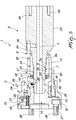
- a spindle according to the invention generally designated by the reference numeral 1, comprises a fixed part 2 and a moveable part 3 which can be coupled, detachably, to the fixed part 2.
- the fixed part 2 is substantially cylindrical, composed of multiple portions, which have mutually different diameters, which are arranged coaxially along a main axis 4.
- a main seat 5 which extends around the main axis 4 and which has an access opening 6 at such axial end of the fixed part 2.
- the main seat 5 is adapted to accommodate a shank-like portion 7 of the moveable part 3.
- Such spindle is provided with means 8 for connecting in rotation about the main axis 4 the moveable part 3 to the fixed part 2.
- axial locking means 9 are provided which are engageable, detachably, with the shank-like portion 7 of the moveable part 3 when this is inserted into the main seat 5 of the fixed part 2 through the access opening 6.
- the means for eliminating the axial play 10 comprise first elastic means 11 which are arranged in the fixed part 2 and which act on the shank-like portion 7 with a force that is oriented parallel to the main axis 4 and which goes in the opposite direction with respect to the axial direction of insertion of the shank-like portion 7 into the main seat 5.
- the main seat 5 has a frustum-shaped portion 5a that narrows in the opposite direction with respect to the access opening 6.
- the frustum-shaped portion 5a of the main seat 5 extends starting from its access opening 6.
- the shank-like portion 7 has a frustum-shaped segment 7a that mates with the frustum-shaped portion 5a of the main seat 5 upon the insertion of the shank-like portion 7 into the main seat 5.
- the main seat 5 has, starting from the access opening 6 and proceeding inward into the main seat 5, the frustum-shaped portion 5a and a substantially cylindrical portion 5b, hereinafter referred to simply as "cylindrical portion 5b".
- the frustum-shaped portion 5a of the main seat 5 is defined in a mating sleeve 12, the axis of which coincides with the main axis 4.
- This mating sleeve 12 is supported, so that it can slide along the main axis 4, within a main body 13 of the fixed part 2 which extends around the main axis 4.
- the first elastic means 11 are interposed between the mating sleeve 12 and the main body 13.
- the main body 13 is substantially cylindrical, and is composed of multiple cylindrical portions that have mutually different diameters and are aligned along the main axis 4.
- the main body 13 is provided internally hollow, being passed through coaxially by a substantially cylindrical passage 14.
- the passage 14 defines a portion of the cylindrical portion 5b of the main seat 5 and, starting from one axial end of the main body 13, has a portion of increased diameter inside which is accommodated, coaxially and slideably, the mating sleeve 12 in which are defined the frustum-shaped portion 5a of the main seat 5 and another portion of the cylindrical portion 5b of the main seat 5 which is aligned with the remaining part of the cylindrical portion 5b of the main seat 5, which is defined by the passage 14.
- the first elastic means 11, constituted by helical springs 16, are arranged.
- the delimiting means 17, in the embodiment shown, comprise a pin 18 which protrudes from the outer lateral surface of the mating sleeve 12 and which is coupled, so that it can slide, inside an axially elongated slot 19, which passes through a side wall of the main body 13.
- the axial locking means 9 comprise an axial shoulder 20 which is defined on the shank-like portion 7 and at least one coupling element 21 which is accommodated in the fixed part 2 and which can move from a release position, in which it does not interfere with the axial shoulder 20 of the shank-like portion 7, to a coupling position, in which it protrudes radially from the lateral surface of the main seat 5 and engages with the axial shoulder 20 of the shank-like portion 7 in order to actuate the retention thereof in the main seat 5, and vice versa.
- the axial shoulder 20 is defined by a groove 22 which extends circumferentially on the lateral surface of the shank-like portion 7, between the frustum-shaped segment 7a and the free end thereof.
- the moveable part 3 consists of a substantially cylindrical portion 23, hereinafter referred to simply as "cylindrical portion 23", from one axial end of which extends the shank-like portion 7 which has a smaller diameter than that of the cylindrical portion 23.
- the shank-like portion 7 has, starting from the cylindrical portion 23 from which it extends, the frustum-shaped segment 7a and a substantially cylindrical portion 7b in which the groove 22 is defined.
- the at least one coupling element 21 is arranged along the cylindrical portion 5b of the main seat 5 and, preferably, comprises at least one ball 24 susceptible of protruding radially toward the inside of the main seat 5 through a corresponding hole 25, which is defined in the main body 13, so as to interfere with the axial shoulder 20.
- three holes 25 are provided, the axes of which are angularly and regularly mutually spaced apart about the main axis 4, which pass through the main body 13.
- a ball 24 is provided that can partially pass through the corresponding hole 25 so as to protrude radially toward the inside of the main seat 5.
- a locking sleeve 26 is fitted which can move parallel to the main axis 4 relative to the main body 13 from a locking position, in which it locks radially the balls 24 of the coupling element 21 in the coupling position in engagement with the axial shoulder 20, to an unlocking position, in which it allows the radial movement of the balls 24 of the coupling element 21 relative to the main body 13 in order to allow their passage from the coupling position to the release position and vice versa.
- the locking sleeve 26 is slideable axially from the locking position to the unlocking position in contrast with the action of second elastic means 27 which are interposed between the locking sleeve 26 and the main body 13. More precisely, the second elastic means 27 are constituted by springs, only one of which is visible in the figures, which are interposed between one axial end of the locking sleeve 26 and a flange 28 of the main body 13 provided at its opposite axial end with respect to the axial end in which the access opening 6 is defined.
- the locking sleeve 26 engages with the balls 24 by way of a conical surface 29 so that the passage of the locking sleeve 26 from the locking position to the unlocking position can also be obtained owing to the thrust exerted by the balls 24 against the locking sleeve 26 upon the insertion of the shank-like portion 7 into the main seat 5.
- a presser sleeve 31 is provided which is arranged around the main body 13 of the fixed part 2 and which can move axially with respect to the main body 13 in order to act on the locking sleeve 26 and cause its transition from the locking position to the unlocking position in contrast with the action of the second elastic means 27. More specifically, the presser sleeve 31 is fitted, so that it can slide, around the main body 13 and engages, with an axial end thereof, against a flange 30 of the locking sleeve 26.
- the presser sleeve 31 is retained on the main body 13 by a covering element 32, from which it protrudes in the direction of the axial end of the main body 13 in which the access opening 6 is defined.
- the covering element 32 is fixed to the main body 13 by way of one or more screws 33.
- the means 8 for connecting in rotation about the main axis 4 of the moveable part 3 with the fixed part 2 comprise a tab 34 which is fixed to the cylindrical portion 23 and which can engage with its end a slot 35 defined on the edge of the access opening 6 of the main seat 5. More precisely, in the embodiment shown, the tab 34 is fixed by way of a screw 36 to the cylindrical portion 23 of the moveable part 3 and protrudes axially from this in the direction of the shank-like portion 7. The tab 34 is insertable into the slot 35 that is defined in the main body 13 of the fixed part 2 starting from the axial end thereof in which the access opening 6 is defined.
- the free end of the shank-like portion 7, intended to be inserted first into the main seat 5, is conveniently beveled so as to press the balls 24 radially away from the main axis 4.
- threaded holes 39 are defined which can be used for fixing, to the moveable part 3, a spool-holder element, which is conventional and not shown for the sake of simplicity.
- the first elastic means 11 push the mating sleeve 12, in which the frustum-shaped portion 5a of the main seat 5 is defined, toward the access opening 6, i.e. toward the outside.
- the mating sleeve 12 is retained inside the main body 13 by the pin 18 which abuts against an axial end of the slot 19 into which it is inserted.
- the locking sleeve 26 is kept in the locking position by the action of the second elastic means 27, as illustrated in Figure 4 .
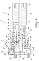
- the shank-like portion 7 When the shank-like portion 7 is inserted into the main seat 5, thus engaging with its beveled end against the balls 24, it pushes them radially away from the main axis 4 and, following the coupling of the balls 24 with the locking sleeve 26 by way of the conical surface 29, causes the passage of the locking sleeve 26 from the locking position to the unlocking position. In this manner, the shank-like portion 7 can proceed in its insertion into the main seat 5 thus bringing its frustum-shaped segment 7a to engage with the frustum-shaped portion 5a defined in the mating sleeve 12, as illustrated in Figure 5 .
- the shank-like portion 7 proceeds further for a portion so that the groove 22 will reach the balls 24. This further continuing of the axial advancement of the shank-like portion 7 inside the main seat 5 causes the compression of the springs 16 that constitute the first elastic means 11.
- the spindle according to the invention fully achieves the set aim in that, by eliminating the axial play between the moveable part and the fixed part, it makes it possible to obtain an extremely precise coupling between these two parts.
- Such precision in the coupling between the moveable part and the fixed part makes it possible to obtain a perfect alignment between the spindles arranged on a same machine and therefore makes it possible to eliminate or at least reduce the winding differences between the spools produced by a same machine.
- the elimination of the axial play between the moveable part and the fixed part of the spindles enables a greater repeatability and precision in the steps of layering of the wire that is wound onto the various spools.
- spindle according to the invention Another advantage of the spindle according to the invention is that it also obtains an elimination of the radial play between the moveable part and the fixed part.
Landscapes
- Engineering & Computer Science (AREA)
- Power Engineering (AREA)
- Manufacturing & Machinery (AREA)
- Turning (AREA)
- Replacement Of Web Rolls (AREA)
- Insulation, Fastening Of Motor, Generator Windings (AREA)
Applications Claiming Priority (1)
| Application Number | Priority Date | Filing Date | Title |
|---|---|---|---|
| ITUB2015A009353A ITUB20159353A1 (it) | 2015-12-22 | 2015-12-22 | Mandrino con attacco rapido, particolarmente per macchine per l'avvolgimento di bobine elettriche. |
Publications (2)
| Publication Number | Publication Date |
|---|---|
| EP3185264A1 true EP3185264A1 (de) | 2017-06-28 |
| EP3185264B1 EP3185264B1 (de) | 2019-11-13 |
Family
ID=55697355
Family Applications (1)
| Application Number | Title | Priority Date | Filing Date |
|---|---|---|---|
| EP16205454.8A Active EP3185264B1 (de) | 2015-12-22 | 2016-12-20 | Spindel mit schnellkupplung, insbesondere für maschinen zum wickeln von elektrischen spulen |
Country Status (2)
| Country | Link |
|---|---|
| EP (1) | EP3185264B1 (de) |
| IT (1) | ITUB20159353A1 (de) |
Cited By (3)
| Publication number | Priority date | Publication date | Assignee | Title |
|---|---|---|---|---|
| EP3438998A1 (de) * | 2017-08-02 | 2019-02-06 | Nortech System SA | Schnellwechselvorrichtung für eine spulenwickelmaschine |
| CN113439007A (zh) * | 2018-11-30 | 2021-09-24 | Gmm股份公司 | 加工块或板坯材料的机器的工具保持器单元,包括该单元的机器和加工块或板坯材料的方法 |
| CN113555210A (zh) * | 2021-06-08 | 2021-10-26 | 珠海航睿智能科技有限公司 | 一种无骨架线圈绕线分离装置 |
Citations (3)
| Publication number | Priority date | Publication date | Assignee | Title |
|---|---|---|---|---|
| US20090090807A1 (en) * | 2007-10-04 | 2009-04-09 | Keihin Corporation | Coil winding system and method for fabricating molded coil |
| EP2246865A2 (de) * | 2009-04-30 | 2010-11-03 | Marsilli & Co. S.P.A. | Vorrichtung zum Kreuzspulen von Draht auf Spulen im Allgemeinen |
| EP2680283A2 (de) * | 2012-06-26 | 2014-01-01 | Nittoku Engineering Co., Ltd. | Vorrichtung und Verfahren zur Herstellung einer nicht kreisförmigen Spule |
-
2015
- 2015-12-22 IT ITUB2015A009353A patent/ITUB20159353A1/it unknown
-
2016
- 2016-12-20 EP EP16205454.8A patent/EP3185264B1/de active Active
Patent Citations (3)
| Publication number | Priority date | Publication date | Assignee | Title |
|---|---|---|---|---|
| US20090090807A1 (en) * | 2007-10-04 | 2009-04-09 | Keihin Corporation | Coil winding system and method for fabricating molded coil |
| EP2246865A2 (de) * | 2009-04-30 | 2010-11-03 | Marsilli & Co. S.P.A. | Vorrichtung zum Kreuzspulen von Draht auf Spulen im Allgemeinen |
| EP2680283A2 (de) * | 2012-06-26 | 2014-01-01 | Nittoku Engineering Co., Ltd. | Vorrichtung und Verfahren zur Herstellung einer nicht kreisförmigen Spule |
Cited By (4)
| Publication number | Priority date | Publication date | Assignee | Title |
|---|---|---|---|---|
| EP3438998A1 (de) * | 2017-08-02 | 2019-02-06 | Nortech System SA | Schnellwechselvorrichtung für eine spulenwickelmaschine |
| CN113439007A (zh) * | 2018-11-30 | 2021-09-24 | Gmm股份公司 | 加工块或板坯材料的机器的工具保持器单元,包括该单元的机器和加工块或板坯材料的方法 |
| CN113439007B (zh) * | 2018-11-30 | 2022-11-08 | Gmm股份公司 | 加工块或板坯材料的机器的工具保持器单元,包括该单元的机器和加工块或板坯材料的方法 |
| CN113555210A (zh) * | 2021-06-08 | 2021-10-26 | 珠海航睿智能科技有限公司 | 一种无骨架线圈绕线分离装置 |
Also Published As
| Publication number | Publication date |
|---|---|
| EP3185264B1 (de) | 2019-11-13 |
| ITUB20159353A1 (it) | 2017-06-22 |
Similar Documents
| Publication | Publication Date | Title |
|---|---|---|
| EP2629310B1 (de) | Mehrfachwickelvorrichtung und Mehrfachwickelverfahren für Spulen | |
| EP2874287B1 (de) | Vorrichtung und Verfahren zum Wickeln und Abschließen von Kernen dynamoelektrischer Maschinen | |
| EP3185264B1 (de) | Spindel mit schnellkupplung, insbesondere für maschinen zum wickeln von elektrischen spulen | |
| US2970844A (en) | Tool holder-axial locking type | |
| CN104641541B (zh) | 卷线装置以及卷线方法 | |
| EP2523885A1 (de) | Reibungsring für reibungsschäfte, insbesondere für wickelspulen | |
| US20220045583A1 (en) | Pulling windings into a stator lamination stack | |
| US2042968A (en) | Holder for tubular supports for coils of strand materials | |
| EP2889990A1 (de) | Vorrichtung zum Einsetzen, Aufwickeln und Beschichten eines Drahts auf einem oder mehreren Stator- oder Rotorkernen | |
| DE102019120637A1 (de) | Baustahlbindewerkzeug | |
| KR101600136B1 (ko) | 회전 스핀들에 척을 고정하기 위한 고정 장치 | |
| CN113767057B (zh) | 卷绕锭子 | |
| CN110015579B (zh) | 卷芯卡盘系统 | |
| EP3438998B1 (de) | Schnellwechselvorrichtung für eine spulenwickelmaschine | |
| US2997782A (en) | Power-inserting tool | |
| KR100970558B1 (ko) | 중공형 공구의 스핀들 콜렛장치 | |
| WO2015074723A1 (en) | Bar feeder | |
| KR101972514B1 (ko) | 스프링 제조장치 | |
| ITUB20159672A1 (it) | Dispositivo anulare di blocco perfezionato per l'avvolgimento di bobine | |
| ITUB20159556A1 (it) | Dispositivo anulare semplificato di blocco per l'avvolgimento di bobine | |
| US1959606A (en) | Mounting device for spools in winding machines | |
| ITTO20070436A1 (it) | "apparecchio e procedimento per avvolgere ed inserire bobine in nuclei di macchine dinamoelettriche" | |
| EP0433919A1 (de) | Vorrichtung zum Herstellen eines Wulstringes für Luftreifen | |
| JP3818639B2 (ja) | 巻枠保持装置 | |
| JPH0314572B2 (de) |
Legal Events
| Date | Code | Title | Description |
|---|---|---|---|
| PUAI | Public reference made under article 153(3) epc to a published international application that has entered the european phase |
Free format text: ORIGINAL CODE: 0009012 |
|
| STAA | Information on the status of an ep patent application or granted ep patent |
Free format text: STATUS: THE APPLICATION HAS BEEN PUBLISHED |
|
| AK | Designated contracting states |
Kind code of ref document: A1 Designated state(s): AL AT BE BG CH CY CZ DE DK EE ES FI FR GB GR HR HU IE IS IT LI LT LU LV MC MK MT NL NO PL PT RO RS SE SI SK SM TR |
|
| AX | Request for extension of the european patent |
Extension state: BA ME |
|
| STAA | Information on the status of an ep patent application or granted ep patent |
Free format text: STATUS: REQUEST FOR EXAMINATION WAS MADE |
|
| 17P | Request for examination filed |
Effective date: 20171102 |
|
| RBV | Designated contracting states (corrected) |
Designated state(s): AL AT BE BG CH CY CZ DE DK EE ES FI FR GB GR HR HU IE IS IT LI LT LU LV MC MK MT NL NO PL PT RO RS SE SI SK SM TR |
|
| GRAP | Despatch of communication of intention to grant a patent |
Free format text: ORIGINAL CODE: EPIDOSNIGR1 |
|
| STAA | Information on the status of an ep patent application or granted ep patent |
Free format text: STATUS: GRANT OF PATENT IS INTENDED |
|
| INTG | Intention to grant announced |
Effective date: 20190529 |
|
| GRAS | Grant fee paid |
Free format text: ORIGINAL CODE: EPIDOSNIGR3 |
|
| GRAA | (expected) grant |
Free format text: ORIGINAL CODE: 0009210 |
|
| STAA | Information on the status of an ep patent application or granted ep patent |
Free format text: STATUS: THE PATENT HAS BEEN GRANTED |
|
| AK | Designated contracting states |
Kind code of ref document: B1 Designated state(s): AL AT BE BG CH CY CZ DE DK EE ES FI FR GB GR HR HU IE IS IT LI LT LU LV MC MK MT NL NO PL PT RO RS SE SI SK SM TR |
|
| REG | Reference to a national code |
Ref country code: CH Ref legal event code: EP Ref country code: AT Ref legal event code: REF Ref document number: 1202527 Country of ref document: AT Kind code of ref document: T Effective date: 20191115 |
|
| REG | Reference to a national code |
Ref country code: CH Ref legal event code: NV Representative=s name: MODIANO AND PARTNERS S.A., CH |
|
| REG | Reference to a national code |
Ref country code: DE Ref legal event code: R096 Ref document number: 602016024207 Country of ref document: DE |
|
| REG | Reference to a national code |
Ref country code: IE Ref legal event code: FG4D |
|
| REG | Reference to a national code |
Ref country code: NL Ref legal event code: MP Effective date: 20191113 |
|
| REG | Reference to a national code |
Ref country code: LT Ref legal event code: MG4D |
|
| PG25 | Lapsed in a contracting state [announced via postgrant information from national office to epo] |
Ref country code: LT Free format text: LAPSE BECAUSE OF FAILURE TO SUBMIT A TRANSLATION OF THE DESCRIPTION OR TO PAY THE FEE WITHIN THE PRESCRIBED TIME-LIMIT Effective date: 20191113 Ref country code: NL Free format text: LAPSE BECAUSE OF FAILURE TO SUBMIT A TRANSLATION OF THE DESCRIPTION OR TO PAY THE FEE WITHIN THE PRESCRIBED TIME-LIMIT Effective date: 20191113 Ref country code: FI Free format text: LAPSE BECAUSE OF FAILURE TO SUBMIT A TRANSLATION OF THE DESCRIPTION OR TO PAY THE FEE WITHIN THE PRESCRIBED TIME-LIMIT Effective date: 20191113 Ref country code: BG Free format text: LAPSE BECAUSE OF FAILURE TO SUBMIT A TRANSLATION OF THE DESCRIPTION OR TO PAY THE FEE WITHIN THE PRESCRIBED TIME-LIMIT Effective date: 20200213 Ref country code: GR Free format text: LAPSE BECAUSE OF FAILURE TO SUBMIT A TRANSLATION OF THE DESCRIPTION OR TO PAY THE FEE WITHIN THE PRESCRIBED TIME-LIMIT Effective date: 20200214 Ref country code: PL Free format text: LAPSE BECAUSE OF FAILURE TO SUBMIT A TRANSLATION OF THE DESCRIPTION OR TO PAY THE FEE WITHIN THE PRESCRIBED TIME-LIMIT Effective date: 20191113 Ref country code: SE Free format text: LAPSE BECAUSE OF FAILURE TO SUBMIT A TRANSLATION OF THE DESCRIPTION OR TO PAY THE FEE WITHIN THE PRESCRIBED TIME-LIMIT Effective date: 20191113 Ref country code: NO Free format text: LAPSE BECAUSE OF FAILURE TO SUBMIT A TRANSLATION OF THE DESCRIPTION OR TO PAY THE FEE WITHIN THE PRESCRIBED TIME-LIMIT Effective date: 20200213 Ref country code: LV Free format text: LAPSE BECAUSE OF FAILURE TO SUBMIT A TRANSLATION OF THE DESCRIPTION OR TO PAY THE FEE WITHIN THE PRESCRIBED TIME-LIMIT Effective date: 20191113 Ref country code: PT Free format text: LAPSE BECAUSE OF FAILURE TO SUBMIT A TRANSLATION OF THE DESCRIPTION OR TO PAY THE FEE WITHIN THE PRESCRIBED TIME-LIMIT Effective date: 20200313 |
|
| PG25 | Lapsed in a contracting state [announced via postgrant information from national office to epo] |
Ref country code: RS Free format text: LAPSE BECAUSE OF FAILURE TO SUBMIT A TRANSLATION OF THE DESCRIPTION OR TO PAY THE FEE WITHIN THE PRESCRIBED TIME-LIMIT Effective date: 20191113 Ref country code: HR Free format text: LAPSE BECAUSE OF FAILURE TO SUBMIT A TRANSLATION OF THE DESCRIPTION OR TO PAY THE FEE WITHIN THE PRESCRIBED TIME-LIMIT Effective date: 20191113 Ref country code: IS Free format text: LAPSE BECAUSE OF FAILURE TO SUBMIT A TRANSLATION OF THE DESCRIPTION OR TO PAY THE FEE WITHIN THE PRESCRIBED TIME-LIMIT Effective date: 20200313 |
|
| PG25 | Lapsed in a contracting state [announced via postgrant information from national office to epo] |
Ref country code: AL Free format text: LAPSE BECAUSE OF FAILURE TO SUBMIT A TRANSLATION OF THE DESCRIPTION OR TO PAY THE FEE WITHIN THE PRESCRIBED TIME-LIMIT Effective date: 20191113 |
|
| PG25 | Lapsed in a contracting state [announced via postgrant information from national office to epo] |
Ref country code: RO Free format text: LAPSE BECAUSE OF FAILURE TO SUBMIT A TRANSLATION OF THE DESCRIPTION OR TO PAY THE FEE WITHIN THE PRESCRIBED TIME-LIMIT Effective date: 20191113 Ref country code: CZ Free format text: LAPSE BECAUSE OF FAILURE TO SUBMIT A TRANSLATION OF THE DESCRIPTION OR TO PAY THE FEE WITHIN THE PRESCRIBED TIME-LIMIT Effective date: 20191113 Ref country code: ES Free format text: LAPSE BECAUSE OF FAILURE TO SUBMIT A TRANSLATION OF THE DESCRIPTION OR TO PAY THE FEE WITHIN THE PRESCRIBED TIME-LIMIT Effective date: 20191113 Ref country code: EE Free format text: LAPSE BECAUSE OF FAILURE TO SUBMIT A TRANSLATION OF THE DESCRIPTION OR TO PAY THE FEE WITHIN THE PRESCRIBED TIME-LIMIT Effective date: 20191113 Ref country code: DK Free format text: LAPSE BECAUSE OF FAILURE TO SUBMIT A TRANSLATION OF THE DESCRIPTION OR TO PAY THE FEE WITHIN THE PRESCRIBED TIME-LIMIT Effective date: 20191113 |
|
| REG | Reference to a national code |
Ref country code: DE Ref legal event code: R097 Ref document number: 602016024207 Country of ref document: DE |
|
| REG | Reference to a national code |
Ref country code: AT Ref legal event code: MK05 Ref document number: 1202527 Country of ref document: AT Kind code of ref document: T Effective date: 20191113 |
|
| REG | Reference to a national code |
Ref country code: BE Ref legal event code: MM Effective date: 20191231 |
|
| PG25 | Lapsed in a contracting state [announced via postgrant information from national office to epo] |
Ref country code: SK Free format text: LAPSE BECAUSE OF FAILURE TO SUBMIT A TRANSLATION OF THE DESCRIPTION OR TO PAY THE FEE WITHIN THE PRESCRIBED TIME-LIMIT Effective date: 20191113 Ref country code: MC Free format text: LAPSE BECAUSE OF FAILURE TO SUBMIT A TRANSLATION OF THE DESCRIPTION OR TO PAY THE FEE WITHIN THE PRESCRIBED TIME-LIMIT Effective date: 20191113 Ref country code: SM Free format text: LAPSE BECAUSE OF FAILURE TO SUBMIT A TRANSLATION OF THE DESCRIPTION OR TO PAY THE FEE WITHIN THE PRESCRIBED TIME-LIMIT Effective date: 20191113 |
|
| PLBE | No opposition filed within time limit |
Free format text: ORIGINAL CODE: 0009261 |
|
| STAA | Information on the status of an ep patent application or granted ep patent |
Free format text: STATUS: NO OPPOSITION FILED WITHIN TIME LIMIT |
|
| 26N | No opposition filed |
Effective date: 20200814 |
|
| PG25 | Lapsed in a contracting state [announced via postgrant information from national office to epo] |
Ref country code: IE Free format text: LAPSE BECAUSE OF NON-PAYMENT OF DUE FEES Effective date: 20191220 Ref country code: LU Free format text: LAPSE BECAUSE OF NON-PAYMENT OF DUE FEES Effective date: 20191220 |
|
| PG25 | Lapsed in a contracting state [announced via postgrant information from national office to epo] |
Ref country code: SI Free format text: LAPSE BECAUSE OF FAILURE TO SUBMIT A TRANSLATION OF THE DESCRIPTION OR TO PAY THE FEE WITHIN THE PRESCRIBED TIME-LIMIT Effective date: 20191113 Ref country code: AT Free format text: LAPSE BECAUSE OF FAILURE TO SUBMIT A TRANSLATION OF THE DESCRIPTION OR TO PAY THE FEE WITHIN THE PRESCRIBED TIME-LIMIT Effective date: 20191113 Ref country code: BE Free format text: LAPSE BECAUSE OF NON-PAYMENT OF DUE FEES Effective date: 20191231 |
|
| PG25 | Lapsed in a contracting state [announced via postgrant information from national office to epo] |
Ref country code: CY Free format text: LAPSE BECAUSE OF FAILURE TO SUBMIT A TRANSLATION OF THE DESCRIPTION OR TO PAY THE FEE WITHIN THE PRESCRIBED TIME-LIMIT Effective date: 20191113 |
|
| PG25 | Lapsed in a contracting state [announced via postgrant information from national office to epo] |
Ref country code: HU Free format text: LAPSE BECAUSE OF FAILURE TO SUBMIT A TRANSLATION OF THE DESCRIPTION OR TO PAY THE FEE WITHIN THE PRESCRIBED TIME-LIMIT; INVALID AB INITIO Effective date: 20161220 Ref country code: MT Free format text: LAPSE BECAUSE OF FAILURE TO SUBMIT A TRANSLATION OF THE DESCRIPTION OR TO PAY THE FEE WITHIN THE PRESCRIBED TIME-LIMIT Effective date: 20191113 |
|
| GBPC | Gb: european patent ceased through non-payment of renewal fee |
Effective date: 20201220 |
|
| PG25 | Lapsed in a contracting state [announced via postgrant information from national office to epo] |
Ref country code: GB Free format text: LAPSE BECAUSE OF NON-PAYMENT OF DUE FEES Effective date: 20201220 |
|
| PG25 | Lapsed in a contracting state [announced via postgrant information from national office to epo] |
Ref country code: TR Free format text: LAPSE BECAUSE OF FAILURE TO SUBMIT A TRANSLATION OF THE DESCRIPTION OR TO PAY THE FEE WITHIN THE PRESCRIBED TIME-LIMIT Effective date: 20191113 |
|
| PG25 | Lapsed in a contracting state [announced via postgrant information from national office to epo] |
Ref country code: MK Free format text: LAPSE BECAUSE OF FAILURE TO SUBMIT A TRANSLATION OF THE DESCRIPTION OR TO PAY THE FEE WITHIN THE PRESCRIBED TIME-LIMIT Effective date: 20191113 |
|
| P01 | Opt-out of the competence of the unified patent court (upc) registered |
Effective date: 20230527 |
|
| REG | Reference to a national code |
Ref country code: CH Ref legal event code: U11 Free format text: ST27 STATUS EVENT CODE: U-0-0-U10-U11 (AS PROVIDED BY THE NATIONAL OFFICE) Effective date: 20260101 |
|
| PGFP | Annual fee paid to national office [announced via postgrant information from national office to epo] |
Ref country code: DE Payment date: 20251212 Year of fee payment: 10 |
|
| PGFP | Annual fee paid to national office [announced via postgrant information from national office to epo] |
Ref country code: IT Payment date: 20251020 Year of fee payment: 10 |
|
| PGFP | Annual fee paid to national office [announced via postgrant information from national office to epo] |
Ref country code: FR Payment date: 20251215 Year of fee payment: 10 |
|
| PGFP | Annual fee paid to national office [announced via postgrant information from national office to epo] |
Ref country code: CH Payment date: 20260101 Year of fee payment: 10 |