EP3186105B1 - Mécanisme de réglage de profondeur de siège - Google Patents
Mécanisme de réglage de profondeur de siège Download PDFInfo
- Publication number
- EP3186105B1 EP3186105B1 EP15770671.4A EP15770671A EP3186105B1 EP 3186105 B1 EP3186105 B1 EP 3186105B1 EP 15770671 A EP15770671 A EP 15770671A EP 3186105 B1 EP3186105 B1 EP 3186105B1
- Authority
- EP
- European Patent Office
- Prior art keywords
- seat
- adjustment mechanism
- frame
- locking arm
- depth adjustment
- Prior art date
- Legal status (The legal status is an assumption and is not a legal conclusion. Google has not performed a legal analysis and makes no representation as to the accuracy of the status listed.)
- Active
Links
Images


Classifications
-
- B—PERFORMING OPERATIONS; TRANSPORTING
- B60—VEHICLES IN GENERAL
- B60N—SEATS SPECIALLY ADAPTED FOR VEHICLES; VEHICLE PASSENGER ACCOMMODATION NOT OTHERWISE PROVIDED FOR
- B60N2/00—Seats specially adapted for vehicles; Arrangement or mounting of seats in vehicles
- B60N2/02—Seats specially adapted for vehicles; Arrangement or mounting of seats in vehicles the seat or part thereof being movable, e.g. adjustable
- B60N2/0224—Non-manual adjustments, e.g. with electrical operation
- B60N2/0226—User interfaces specially adapted for seat adjustment
- B60N2/0228—Hand-activated mechanical switches
-
- B—PERFORMING OPERATIONS; TRANSPORTING
- B60—VEHICLES IN GENERAL
- B60N—SEATS SPECIALLY ADAPTED FOR VEHICLES; VEHICLE PASSENGER ACCOMMODATION NOT OTHERWISE PROVIDED FOR
- B60N2/00—Seats specially adapted for vehicles; Arrangement or mounting of seats in vehicles
- B60N2/02—Seats specially adapted for vehicles; Arrangement or mounting of seats in vehicles the seat or part thereof being movable, e.g. adjustable
- B60N2/04—Seats specially adapted for vehicles; Arrangement or mounting of seats in vehicles the seat or part thereof being movable, e.g. adjustable the whole seat being movable
- B60N2/06—Seats specially adapted for vehicles; Arrangement or mounting of seats in vehicles the seat or part thereof being movable, e.g. adjustable the whole seat being movable slidable
-
- B—PERFORMING OPERATIONS; TRANSPORTING
- B60—VEHICLES IN GENERAL
- B60N—SEATS SPECIALLY ADAPTED FOR VEHICLES; VEHICLE PASSENGER ACCOMMODATION NOT OTHERWISE PROVIDED FOR
- B60N2/00—Seats specially adapted for vehicles; Arrangement or mounting of seats in vehicles
- B60N2/02—Seats specially adapted for vehicles; Arrangement or mounting of seats in vehicles the seat or part thereof being movable, e.g. adjustable
- B60N2/04—Seats specially adapted for vehicles; Arrangement or mounting of seats in vehicles the seat or part thereof being movable, e.g. adjustable the whole seat being movable
- B60N2/06—Seats specially adapted for vehicles; Arrangement or mounting of seats in vehicles the seat or part thereof being movable, e.g. adjustable the whole seat being movable slidable
- B60N2/07—Slide construction
- B60N2/0722—Constructive details
- B60N2/0732—Attachment of seat frame to the slide, e.g. eyelets
-
- B—PERFORMING OPERATIONS; TRANSPORTING
- B60—VEHICLES IN GENERAL
- B60N—SEATS SPECIALLY ADAPTED FOR VEHICLES; VEHICLE PASSENGER ACCOMMODATION NOT OTHERWISE PROVIDED FOR
- B60N2/00—Seats specially adapted for vehicles; Arrangement or mounting of seats in vehicles
- B60N2/02—Seats specially adapted for vehicles; Arrangement or mounting of seats in vehicles the seat or part thereof being movable, e.g. adjustable
- B60N2/04—Seats specially adapted for vehicles; Arrangement or mounting of seats in vehicles the seat or part thereof being movable, e.g. adjustable the whole seat being movable
- B60N2/06—Seats specially adapted for vehicles; Arrangement or mounting of seats in vehicles the seat or part thereof being movable, e.g. adjustable the whole seat being movable slidable
- B60N2/08—Seats specially adapted for vehicles; Arrangement or mounting of seats in vehicles the seat or part thereof being movable, e.g. adjustable the whole seat being movable slidable characterised by the locking device
- B60N2/0806—Seats specially adapted for vehicles; Arrangement or mounting of seats in vehicles the seat or part thereof being movable, e.g. adjustable the whole seat being movable slidable characterised by the locking device with pin alignment systems, e.g. with at least one of a plurality of locking pins always aligned w.r.t. at least one of a plurality of pin-receiving elements
-
- B—PERFORMING OPERATIONS; TRANSPORTING
- B60—VEHICLES IN GENERAL
- B60N—SEATS SPECIALLY ADAPTED FOR VEHICLES; VEHICLE PASSENGER ACCOMMODATION NOT OTHERWISE PROVIDED FOR
- B60N2/00—Seats specially adapted for vehicles; Arrangement or mounting of seats in vehicles
- B60N2/02—Seats specially adapted for vehicles; Arrangement or mounting of seats in vehicles the seat or part thereof being movable, e.g. adjustable
- B60N2/04—Seats specially adapted for vehicles; Arrangement or mounting of seats in vehicles the seat or part thereof being movable, e.g. adjustable the whole seat being movable
- B60N2/06—Seats specially adapted for vehicles; Arrangement or mounting of seats in vehicles the seat or part thereof being movable, e.g. adjustable the whole seat being movable slidable
- B60N2/08—Seats specially adapted for vehicles; Arrangement or mounting of seats in vehicles the seat or part thereof being movable, e.g. adjustable the whole seat being movable slidable characterised by the locking device
- B60N2/0812—Location of the latch
- B60N2/0825—Location of the latch outside the rail
-
- B—PERFORMING OPERATIONS; TRANSPORTING
- B60—VEHICLES IN GENERAL
- B60N—SEATS SPECIALLY ADAPTED FOR VEHICLES; VEHICLE PASSENGER ACCOMMODATION NOT OTHERWISE PROVIDED FOR
- B60N2/00—Seats specially adapted for vehicles; Arrangement or mounting of seats in vehicles
- B60N2/02—Seats specially adapted for vehicles; Arrangement or mounting of seats in vehicles the seat or part thereof being movable, e.g. adjustable
- B60N2/04—Seats specially adapted for vehicles; Arrangement or mounting of seats in vehicles the seat or part thereof being movable, e.g. adjustable the whole seat being movable
- B60N2/06—Seats specially adapted for vehicles; Arrangement or mounting of seats in vehicles the seat or part thereof being movable, e.g. adjustable the whole seat being movable slidable
- B60N2/08—Seats specially adapted for vehicles; Arrangement or mounting of seats in vehicles the seat or part thereof being movable, e.g. adjustable the whole seat being movable slidable characterised by the locking device
- B60N2/0831—Movement of the latch
- B60N2/0837—Movement of the latch pivoting
- B60N2/085—Movement of the latch pivoting about a transversal axis
-
- B—PERFORMING OPERATIONS; TRANSPORTING
- B60—VEHICLES IN GENERAL
- B60N—SEATS SPECIALLY ADAPTED FOR VEHICLES; VEHICLE PASSENGER ACCOMMODATION NOT OTHERWISE PROVIDED FOR
- B60N2/00—Seats specially adapted for vehicles; Arrangement or mounting of seats in vehicles
- B60N2/02—Seats specially adapted for vehicles; Arrangement or mounting of seats in vehicles the seat or part thereof being movable, e.g. adjustable
- B60N2/04—Seats specially adapted for vehicles; Arrangement or mounting of seats in vehicles the seat or part thereof being movable, e.g. adjustable the whole seat being movable
- B60N2/06—Seats specially adapted for vehicles; Arrangement or mounting of seats in vehicles the seat or part thereof being movable, e.g. adjustable the whole seat being movable slidable
- B60N2/08—Seats specially adapted for vehicles; Arrangement or mounting of seats in vehicles the seat or part thereof being movable, e.g. adjustable the whole seat being movable slidable characterised by the locking device
- B60N2/0881—Activation of the latches by the control mechanism
-
- B—PERFORMING OPERATIONS; TRANSPORTING
- B60—VEHICLES IN GENERAL
- B60N—SEATS SPECIALLY ADAPTED FOR VEHICLES; VEHICLE PASSENGER ACCOMMODATION NOT OTHERWISE PROVIDED FOR
- B60N2/00—Seats specially adapted for vehicles; Arrangement or mounting of seats in vehicles
- B60N2/90—Details or parts not otherwise provided for
- B60N2/919—Positioning and locking mechanisms
- B60N2/933—Positioning and locking mechanisms rotatable
Definitions
- the invention relates to a seat depth adjustment mechanism which will be used in the vehicle seats.
- the invention especially relates to a system, in which seating section of the seat can be adjusted for comfort by being slid back and forth independently of the seat under the user control.
- actuator moves by rotating the metal piece.
- Linear contact operates between the actuator and the metal piece.
- Abrasions occurring as a result of such an operation way may affect the operation of the system and the effort of the operation.
- the system operates by moving a flexible metal.
- the system operates by releasing from the pin fixed in the seat as a result of triggering the lever.
- the button is required to be pulled to the last level to operate. The system does not operate when said button is not pulled fully. A serious effort is needed for the user so as to pull the button to the last level.
- patent application numbered EP1870277A2 relates to a seat slide locator for a seat mount assembly on a tractor, riding mower, or off-road utility vehicle.
- the present invention aims to eliminate the above mentioned drawbacks. that are overcome by a seat depth adjustment mechanism comprising the features of claim 1.
- the advantages of the system according to the invention over the applications used in the prior art are specified below:
- the button and the locking parts are separate from each other and positioned in a manner that they only linearly contact with each other.
- the button and the locking part are the same product. Namely, they are one piece. Thus, action is achieved with an additional part in the prior art. Based on these explanations, in the system according to the invention, the system can be disassembled without the need of any additional/second equipment.
- a seat depth adjustment mechanism which is used in the vehicle seat and provides the adjustment of the seat depth of the seat positioned on the frame fixed to the vehicle, wherein said seat depth adjustment mechanism comprises
- said mechanism is characterized in that
- said mechanism is characterized by
- said mechanism is characterized by
- said mechanism is characterized by
- said mechanism is characterized by
- said mechanism is characterized by
- said mechanism is characterized in that
- said mechanism is characterized in that
- said mechanism is characterized in that
- said mechanism is characterized by
- the seat depth adjustment mechanism according to the invention may comprise the following components:
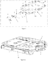
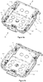
- Disassembled top perspective view of the seat depth adjustment mechanism according to the invention is given in Figure 1 ; assembled top perspective view of the seat depth adjustment mechanism is given in Figure 2a ; assembled top perspective detailed view of the seat depth adjustment mechanism is given Figure 2b ; and bottom perspective view of the seat depth adjustment mechanism according to the invention when assembled, which also shows the level adjustment part (19) fixed to the frame (18) is given in Figure 2c .
- Seat (1) is the movable part on which the user sits and which can be moved forward and backward.
- Frame (18) is the fixed part which is fixed to the car. Seat (1) can be moved forward and backward on the frame.
- Button (8) and locking arm (2) are fixed to each other by means of the arm and button fixing elements (5) which are preferably screw. Downward and upward movement of the button (8) and the locking arm (2) passing through the arm movement space (112) is provided by means of the shaft (10) and left locking spring (3) and right locking spring (4) positioned on the shaft (10). Left locking spring (3) and right locking spring (4) also provide the button (8) and the locking arm (2) to return to their former position after the movement.
- Shaft (10) is fixed to the seat (1) by means of the shaft connectors (7) from its two ends. Shaft connectors (7) also center the locking arm (2) into the arm movement space (112). Shaft connectors (7) are fixed to the seat (1) by means of the shaft connectors retainers (6).
- Fixing protrusion (21) is formed on the locking arm (2).
- Level adjustment part (19) is fixed to the frame (18).
- Fixing holes (191) are formed on the level adjustment part (19). Movement of the seat (1) on the frame (18) is provided by removing the fixing protrusion (21) from the fixing hole (191) and sliding the seat (1) forward and backward on the frame. Fixing the seat (1) on the frame (18), namely ending the movement thereof on the frame (18), is achieved by fitting the fixing protrusion (21) into the desired fixing hole (191) ( Figure 2b, Figure 2c ). Thereby, seat depth is adjusted.
- Figure 3b when user force is applied to the button (8), upward movement of the button (8) and downward movement of the fixing protrusion (21) on the locking arm (2) fixed to the button (8) are seen. When the user force applied to the button (8) is removed, however, button (8) and locking arm (2) move in the opposite direction by means of the left locking spring (3) and right locking spring (4) ( Figure 3a ) and return to their former positions in horizontal position.
- Figure 4 shows a drawing of the safety lock system which prevents the seat (1) from separating from the frame (18) in an uncontrolled manner
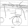
- Figure 5 shows a detailed drawing of the safety lock system.
- Safety lock system consists of a movement channel (111) formed on the seat (1); slide (13) on which said movement channel (111) moves; connector (14); seat fixing element (16) fixed to the connector (14); fixing element (17) fixing the seat fixing element (16); and retaining element (9). Moreover, return spring (15) is positioned on the seat fixing element (16). However, retaining element (9) is positioned in the end point of the movement channel (111).
- Connector (14) is preferably nut
- seat fixing element (16) is preferably pin
- fixing element (17) is preferably pin bearing.
- Said safety lock system is provided in preferably 4 corners of the seat (1).
- the retaining element (9) preferably made of plastic prevents the connector (14) from contacting with the end point section of the movement channel (111) of the seat (1) in the rear edge (B) direction of the seat (1).
- Connector (14) strikes to the retaining element (9) instead of the seat (1).
- retaining element (9) both prevents the sound likely to occur during contact and provides comfort during said striking.
- Fixing protrusion (17) is a part connected to the frame (18).
- Seat fixing element (16) is fitted through the fixing element (17).
- return spring (15) and connector (14) are assembled to the seat fixing element (16) from the top.
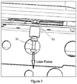
- the connector (14) disposed in the top section will be separated from the seat (1) and the seat (1) is allowed to be removed.
- the seat fixing element (16) is released, on the other hand, thanks to the return spring (15) the seat fixing element (16) returns to its former position. Seat (1) cannot be assembled in this position.
- the seat fixing element (16) When the seat (1) is desired to be reassembled to its place, namely to the frame (18), the seat fixing element (16) will again be pulled downward and then the seat (1) will be assembled to the system and when the seat fixing element (16) is released, the seat (1) will be assembled to its place ( Figure 5 , Figure 7 ).
Landscapes
- Engineering & Computer Science (AREA)
- Aviation & Aerospace Engineering (AREA)
- Transportation (AREA)
- Mechanical Engineering (AREA)
- Human Computer Interaction (AREA)
- Seats For Vehicles (AREA)
Claims (11)
- Mécanisme de réglage de profondeur de siège qui est utilisé dans les sièges de véhicule et permet le réglage de la profondeur de siège du siège (1) positionné sur le cadre (18) fixé au véhicule, comprenant- une partie de réglage de niveau (19) pouvant se raccorder au cadre (18) ;- des trous de fixation (191) formés sur ladite partie de réglage de niveau (19) ;- un bras de verrouillage (2), dont l'extrémité avant est déplacée vers le haut par l'utilisateur avant que le siège ne soit déplacé vers l'avant ou vers l'arrière par l'utilisateur afin d'obtenir le réglage de la profondeur de siège ; qui est positionné dans le bord avant (A) du siège (1) et s'étend selon une direction parallèle aux bords latéraux (C) du siège (1)- au moins un ressort de verrouillage qui ramène le bras de verrouillage (2) à sa position initiale lorsque la force de l'utilisateur appliquée audit bras de verrouillage (2) est supprimée et qui est relié avec ledit bras de verrouillage (2) ;- une saillie de fixation (21) qui est formée sur ledit bras de verrouillage (2) et est positionnée à l'intérieur dudit trou de fixation (191) lorsque ledit ressort de verrouillage ramène le bras de verrouillage (2) à sa position initiale afin de permettre audit siège (1) d'être fixé audit cadre (18) ;- un espace de mouvement de bras (112) qui permet le raccord dudit bras de verrouillage (2) à la partie réglage de niveau (19) et le mouvement vers le bas et vers le haut du bras de verrouillage (2), à travers lequel ledit bras de verrouillage (2) passe et qui est formé dans le bord avant du siège (1) ;- un arbre (10) sur lequel ledit ressort de verrouillage est positionné ;- les raccords d'arbre (7) pour le raccordement dudit arbre (10) au siège (1).
- Mécanisme de réglage de profondeur de siège selon la revendication 1, caractérisé en ce que- ledit ressort de verrouillage est le ressort de verrouillage droit (4) et/ou le ressort de verrouillage gauche (3).
- Mécanisme de réglage de profondeur de siège selon la revendication 1 ou 2, caractérisé par- un bouton (8), qui permet à l'utilisateur de déplacer le bras de verrouillage (2) et est raccordé audit bras de verrouillage (2).
- Mécanisme de réglage de profondeur de siège selon la revendication 3, caractérisé par- un élément de fixation de bouton et de bras (5) qui relie ledit bras de verrouillage (2) et ledit bouton (8).
- Mécanisme de réglage de profondeur de siège selon la revendication 1, caractérisé par- un élément de retenue de raccord d'arbre (6) qui fixe ledit raccord d'arbre (7) au siège (1).
- Mécanisme de réglage de profondeur de siège selon la revendication 1, caractérisé par- au moins un canal de mouvement (111) formé dans les bords latéraux dudit siège (1) ;- un coulisseau (13) sur lequel ledit canal de mouvement (111) se déplace durant le mouvement vers l'arrière et vers l'avant du siège (1) sur le cadre (18) par l'utilisateur et qui est fixé audit cadre (18).
- Mécanisme de réglage de profondeur de siège selon la revendication 6, caractérisé par- un raccord (14) qui fixe le siège (1) au cadre (18) et est positionné dans ledit canal de mouvement (111) ;- un élément de fixation de siège (16) qui fixe ledit raccord (14) au cadre (18) ;- un élément de fixation (17), qui fixe ledit élément de fixation de siège (16) au cadre (18) ;- un ressort de rappel (15) qui permet audit raccord (14) d'être assemblé ou désassemblé dudit élément de fixation de siège (16).
- Mécanisme de réglage de profondeur de siège selon la revendication 4, caractérisé en ce que- ledit élément de fixation de bras et de bouton (5) est une vis.
- Mécanisme de réglage de profondeur de siège selon la revendication 7, caractérisé en ce que- ledit raccord (14) est un écrou.
- Mécanisme de réglage de profondeur de siège selon la revendication 7, caractérisé en ce que- ledit élément de fixation de siège (16) est une broche.
- Mécanisme de réglage de profondeur de siège selon la revendication 7, caractérisé par- un élément de retenue (9) composé de plastique qui est positionné sur ledit siège (1) au niveau du point d'extrémité dudit canal de mouvement (111) selon la direction de bord arrière (B) du siège (1).
Priority Applications (1)
| Application Number | Priority Date | Filing Date | Title |
|---|---|---|---|
| PL15770671T PL3186105T3 (pl) | 2015-08-07 | 2015-08-07 | Mechanizm regulacji głębokości siedzenia |
Applications Claiming Priority (1)
| Application Number | Priority Date | Filing Date | Title |
|---|---|---|---|
| PCT/TR2015/050059 WO2017026949A1 (fr) | 2015-08-07 | 2015-08-07 | Mécanisme de réglage de profondeur de siège |
Publications (2)
| Publication Number | Publication Date |
|---|---|
| EP3186105A1 EP3186105A1 (fr) | 2017-07-05 |
| EP3186105B1 true EP3186105B1 (fr) | 2018-08-01 |
Family
ID=54197037
Family Applications (1)
| Application Number | Title | Priority Date | Filing Date |
|---|---|---|---|
| EP15770671.4A Active EP3186105B1 (fr) | 2015-08-07 | 2015-08-07 | Mécanisme de réglage de profondeur de siège |
Country Status (4)
| Country | Link |
|---|---|
| EP (1) | EP3186105B1 (fr) |
| ES (1) | ES2688043T3 (fr) |
| PL (1) | PL3186105T3 (fr) |
| WO (1) | WO2017026949A1 (fr) |
Cited By (1)
| Publication number | Priority date | Publication date | Assignee | Title |
|---|---|---|---|---|
| US11904730B2 (en) | 2021-05-14 | 2024-02-20 | Techtronic Cordless Gp | Removable seats and lawnmowers with removable seats |
Family Cites Families (5)
| Publication number | Priority date | Publication date | Assignee | Title |
|---|---|---|---|---|
| FR1094483A (fr) * | 1953-11-21 | 1955-05-20 | Faure Bertrand Ets | Perfectionnements apportés aux sièges de position réglable, notamment pour véhicules automobiles |
| NL292919A (fr) * | 1962-11-19 | |||
| DE1680150C3 (de) * | 1968-03-14 | 1978-07-20 | Keiper Automobiltechnik Gmbh & Co Kg, 5630 Remscheid | Feststellvorrichtung für einen in Längsrichtung verschiebbaren Sitz, insbesondere für Kraftfahrzeuge |
| US7648115B2 (en) * | 2006-06-20 | 2010-01-19 | Deere & Company | Seat slide locator |
| US9216673B2 (en) * | 2008-03-05 | 2015-12-22 | Milsco Manufacturing Company, A Unit Of Jason Incorporated | Low profile seat position adjustment system |
-
2015
- 2015-08-07 EP EP15770671.4A patent/EP3186105B1/fr active Active
- 2015-08-07 PL PL15770671T patent/PL3186105T3/pl unknown
- 2015-08-07 WO PCT/TR2015/050059 patent/WO2017026949A1/fr not_active Ceased
- 2015-08-07 ES ES15770671.4T patent/ES2688043T3/es active Active
Cited By (1)
| Publication number | Priority date | Publication date | Assignee | Title |
|---|---|---|---|---|
| US11904730B2 (en) | 2021-05-14 | 2024-02-20 | Techtronic Cordless Gp | Removable seats and lawnmowers with removable seats |
Also Published As
| Publication number | Publication date |
|---|---|
| ES2688043T3 (es) | 2018-10-30 |
| WO2017026949A1 (fr) | 2017-02-16 |
| PL3186105T3 (pl) | 2018-12-31 |
| EP3186105A1 (fr) | 2017-07-05 |
Similar Documents
| Publication | Publication Date | Title |
|---|---|---|
| DE102016111974B4 (de) | Vorrichtung zum Öffnen und Schließen einer verschiebbaren Armlehnenkonsole | |
| US8899685B2 (en) | Vehicle seat headrest assembly having vertical and longitudinal adjustment | |
| CN102227334B (zh) | 用于交通工具座椅的可靠啮合锁定系统 | |
| US8201667B2 (en) | Braking system with single actuation for a stroller | |
| CN103158585B (zh) | 用于交通工具座椅的主动啮合锁定机构 | |
| EP2980343B1 (fr) | Appareil de poignee de porte pour vehicule | |
| US9731630B2 (en) | Seat slide device | |
| US9873358B2 (en) | Locking device for baby car seat | |
| EP2939872B1 (fr) | Siège électrique avec système d'entrée manuelle complet | |
| EP3488733B1 (fr) | Ensemble rail de glissière et kit rail de celui-ci | |
| US20110148171A1 (en) | Height adjustable headrest for an automobile seat backrest | |
| US20160145894A1 (en) | Latch system for door | |
| US9150125B2 (en) | Vehicle slide rail device | |
| DE102012205630A1 (de) | Fahrzeugsitz | |
| DE112011104972T5 (de) | Fahrzeugsitz-Schienenanordnung mit Erinnerungsvermögen und mit externer Freigabe | |
| EP3235401A1 (fr) | Appuie-tête | |
| CN109835219B (zh) | 一种座椅姿态调整装置及安全座椅 | |
| EP3253604A1 (fr) | Système muni d'un couvercle, destiné au toit d'un véhicule | |
| US9061606B2 (en) | Electric release manual seat | |
| EP3186105B1 (fr) | Mécanisme de réglage de profondeur de siège | |
| US10040374B2 (en) | Seat slide device | |
| DE102013224965A1 (de) | Klappbare Fahrzeug-Kopfstützenanordnung | |
| JP5710831B1 (ja) | ヘッドレスト用傾倒装置及びヘッドレスト | |
| WO2014125507A2 (fr) | Système de coulissement du type à verrouillage inférieur interne | |
| CN114789683A (zh) | 安全座椅及其底座 |
Legal Events
| Date | Code | Title | Description |
|---|---|---|---|
| PUAI | Public reference made under article 153(3) epc to a published international application that has entered the european phase |
Free format text: ORIGINAL CODE: 0009012 |
|
| 17P | Request for examination filed |
Effective date: 20170306 |
|
| AK | Designated contracting states |
Kind code of ref document: A1 Designated state(s): AL AT BE BG CH CY CZ DE DK EE ES FI FR GB GR HR HU IE IS IT LI LT LU LV MC MK MT NL NO PL PT RO RS SE SI SK SM TR |
|
| AX | Request for extension of the european patent |
Extension state: BA ME |
|
| REG | Reference to a national code |
Ref country code: DE Ref legal event code: R079 Ref document number: 602015014395 Country of ref document: DE Free format text: PREVIOUS MAIN CLASS: B60N0002020000 Ipc: B60N0002900000 |
|
| GRAP | Despatch of communication of intention to grant a patent |
Free format text: ORIGINAL CODE: EPIDOSNIGR1 |
|
| RIC1 | Information provided on ipc code assigned before grant |
Ipc: B60N 2/08 20060101ALI20180326BHEP Ipc: B60N 2/02 20060101ALI20180326BHEP Ipc: B60N 2/07 20060101ALI20180326BHEP Ipc: B60N 2/06 20060101ALI20180326BHEP Ipc: B60N 2/90 20180101AFI20180326BHEP |
|
| DAX | Request for extension of the european patent (deleted) | ||
| INTG | Intention to grant announced |
Effective date: 20180424 |
|
| GRAS | Grant fee paid |
Free format text: ORIGINAL CODE: EPIDOSNIGR3 |
|
| GRAA | (expected) grant |
Free format text: ORIGINAL CODE: 0009210 |
|
| AK | Designated contracting states |
Kind code of ref document: B1 Designated state(s): AL AT BE BG CH CY CZ DE DK EE ES FI FR GB GR HR HU IE IS IT LI LT LU LV MC MK MT NL NO PL PT RO RS SE SI SK SM TR |
|
| DAV | Request for validation of the european patent (deleted) | ||
| REG | Reference to a national code |
Ref country code: GB Ref legal event code: FG4D |
|
| REG | Reference to a national code |
Ref country code: CH Ref legal event code: EP Ref country code: AT Ref legal event code: REF Ref document number: 1023899 Country of ref document: AT Kind code of ref document: T Effective date: 20180815 |
|
| REG | Reference to a national code |
Ref country code: IE Ref legal event code: FG4D |
|
| REG | Reference to a national code |
Ref country code: DE Ref legal event code: R096 Ref document number: 602015014395 Country of ref document: DE |
|
| RAP2 | Party data changed (patent owner data changed or rights of a patent transferred) |
Owner name: ASSAN HANIL OTOMOTIV SANAYI VE TICARET ANONIM SIRK |
|
| REG | Reference to a national code |
Ref country code: FR Ref legal event code: PLFP Year of fee payment: 4 |
|
| REG | Reference to a national code |
Ref country code: NL Ref legal event code: FP |
|
| REG | Reference to a national code |
Ref country code: ES Ref legal event code: FG2A Ref document number: 2688043 Country of ref document: ES Kind code of ref document: T3 Effective date: 20181030 |
|
| REG | Reference to a national code |
Ref country code: SE Ref legal event code: TRGR |
|
| REG | Reference to a national code |
Ref country code: LT Ref legal event code: MG4D |
|
| REG | Reference to a national code |
Ref country code: AT Ref legal event code: MK05 Ref document number: 1023899 Country of ref document: AT Kind code of ref document: T Effective date: 20180801 |
|
| PG25 | Lapsed in a contracting state [announced via postgrant information from national office to epo] |
Ref country code: GR Free format text: LAPSE BECAUSE OF FAILURE TO SUBMIT A TRANSLATION OF THE DESCRIPTION OR TO PAY THE FEE WITHIN THE PRESCRIBED TIME-LIMIT Effective date: 20181102 Ref country code: AT Free format text: LAPSE BECAUSE OF FAILURE TO SUBMIT A TRANSLATION OF THE DESCRIPTION OR TO PAY THE FEE WITHIN THE PRESCRIBED TIME-LIMIT Effective date: 20180801 Ref country code: BG Free format text: LAPSE BECAUSE OF FAILURE TO SUBMIT A TRANSLATION OF THE DESCRIPTION OR TO PAY THE FEE WITHIN THE PRESCRIBED TIME-LIMIT Effective date: 20181101 Ref country code: IS Free format text: LAPSE BECAUSE OF FAILURE TO SUBMIT A TRANSLATION OF THE DESCRIPTION OR TO PAY THE FEE WITHIN THE PRESCRIBED TIME-LIMIT Effective date: 20181201 Ref country code: NO Free format text: LAPSE BECAUSE OF FAILURE TO SUBMIT A TRANSLATION OF THE DESCRIPTION OR TO PAY THE FEE WITHIN THE PRESCRIBED TIME-LIMIT Effective date: 20181101 Ref country code: LT Free format text: LAPSE BECAUSE OF FAILURE TO SUBMIT A TRANSLATION OF THE DESCRIPTION OR TO PAY THE FEE WITHIN THE PRESCRIBED TIME-LIMIT Effective date: 20180801 Ref country code: RS Free format text: LAPSE BECAUSE OF FAILURE TO SUBMIT A TRANSLATION OF THE DESCRIPTION OR TO PAY THE FEE WITHIN THE PRESCRIBED TIME-LIMIT Effective date: 20180801 Ref country code: FI Free format text: LAPSE BECAUSE OF FAILURE TO SUBMIT A TRANSLATION OF THE DESCRIPTION OR TO PAY THE FEE WITHIN THE PRESCRIBED TIME-LIMIT Effective date: 20180801 |
|
| PG25 | Lapsed in a contracting state [announced via postgrant information from national office to epo] |
Ref country code: AL Free format text: LAPSE BECAUSE OF FAILURE TO SUBMIT A TRANSLATION OF THE DESCRIPTION OR TO PAY THE FEE WITHIN THE PRESCRIBED TIME-LIMIT Effective date: 20180801 Ref country code: LV Free format text: LAPSE BECAUSE OF FAILURE TO SUBMIT A TRANSLATION OF THE DESCRIPTION OR TO PAY THE FEE WITHIN THE PRESCRIBED TIME-LIMIT Effective date: 20180801 Ref country code: HR Free format text: LAPSE BECAUSE OF FAILURE TO SUBMIT A TRANSLATION OF THE DESCRIPTION OR TO PAY THE FEE WITHIN THE PRESCRIBED TIME-LIMIT Effective date: 20180801 |
|
| REG | Reference to a national code |
Ref country code: CH Ref legal event code: PL |
|
| PG25 | Lapsed in a contracting state [announced via postgrant information from national office to epo] |
Ref country code: EE Free format text: LAPSE BECAUSE OF FAILURE TO SUBMIT A TRANSLATION OF THE DESCRIPTION OR TO PAY THE FEE WITHIN THE PRESCRIBED TIME-LIMIT Effective date: 20180801 Ref country code: CH Free format text: LAPSE BECAUSE OF NON-PAYMENT OF DUE FEES Effective date: 20180831 Ref country code: MC Free format text: LAPSE BECAUSE OF FAILURE TO SUBMIT A TRANSLATION OF THE DESCRIPTION OR TO PAY THE FEE WITHIN THE PRESCRIBED TIME-LIMIT Effective date: 20180801 Ref country code: LI Free format text: LAPSE BECAUSE OF NON-PAYMENT OF DUE FEES Effective date: 20180831 Ref country code: LU Free format text: LAPSE BECAUSE OF NON-PAYMENT OF DUE FEES Effective date: 20180807 Ref country code: RO Free format text: LAPSE BECAUSE OF FAILURE TO SUBMIT A TRANSLATION OF THE DESCRIPTION OR TO PAY THE FEE WITHIN THE PRESCRIBED TIME-LIMIT Effective date: 20180801 |
|
| REG | Reference to a national code |
Ref country code: DE Ref legal event code: R097 Ref document number: 602015014395 Country of ref document: DE |
|
| REG | Reference to a national code |
Ref country code: BE Ref legal event code: MM Effective date: 20180831 |
|
| REG | Reference to a national code |
Ref country code: IE Ref legal event code: MM4A |
|
| PG25 | Lapsed in a contracting state [announced via postgrant information from national office to epo] |
Ref country code: SK Free format text: LAPSE BECAUSE OF FAILURE TO SUBMIT A TRANSLATION OF THE DESCRIPTION OR TO PAY THE FEE WITHIN THE PRESCRIBED TIME-LIMIT Effective date: 20180801 Ref country code: SM Free format text: LAPSE BECAUSE OF FAILURE TO SUBMIT A TRANSLATION OF THE DESCRIPTION OR TO PAY THE FEE WITHIN THE PRESCRIBED TIME-LIMIT Effective date: 20180801 Ref country code: DK Free format text: LAPSE BECAUSE OF FAILURE TO SUBMIT A TRANSLATION OF THE DESCRIPTION OR TO PAY THE FEE WITHIN THE PRESCRIBED TIME-LIMIT Effective date: 20180801 |
|
| PLBE | No opposition filed within time limit |
Free format text: ORIGINAL CODE: 0009261 |
|
| STAA | Information on the status of an ep patent application or granted ep patent |
Free format text: STATUS: NO OPPOSITION FILED WITHIN TIME LIMIT |
|
| 26N | No opposition filed |
Effective date: 20190503 |
|
| PG25 | Lapsed in a contracting state [announced via postgrant information from national office to epo] |
Ref country code: IE Free format text: LAPSE BECAUSE OF NON-PAYMENT OF DUE FEES Effective date: 20180807 |
|
| PG25 | Lapsed in a contracting state [announced via postgrant information from national office to epo] |
Ref country code: BE Free format text: LAPSE BECAUSE OF NON-PAYMENT OF DUE FEES Effective date: 20180831 Ref country code: SI Free format text: LAPSE BECAUSE OF FAILURE TO SUBMIT A TRANSLATION OF THE DESCRIPTION OR TO PAY THE FEE WITHIN THE PRESCRIBED TIME-LIMIT Effective date: 20180801 |
|
| PG25 | Lapsed in a contracting state [announced via postgrant information from national office to epo] |
Ref country code: MT Free format text: LAPSE BECAUSE OF NON-PAYMENT OF DUE FEES Effective date: 20180807 |
|
| PG25 | Lapsed in a contracting state [announced via postgrant information from national office to epo] |
Ref country code: PT Free format text: LAPSE BECAUSE OF FAILURE TO SUBMIT A TRANSLATION OF THE DESCRIPTION OR TO PAY THE FEE WITHIN THE PRESCRIBED TIME-LIMIT Effective date: 20180801 |
|
| PG25 | Lapsed in a contracting state [announced via postgrant information from national office to epo] |
Ref country code: CY Free format text: LAPSE BECAUSE OF FAILURE TO SUBMIT A TRANSLATION OF THE DESCRIPTION OR TO PAY THE FEE WITHIN THE PRESCRIBED TIME-LIMIT Effective date: 20180801 Ref country code: MK Free format text: LAPSE BECAUSE OF NON-PAYMENT OF DUE FEES Effective date: 20180801 Ref country code: HU Free format text: LAPSE BECAUSE OF FAILURE TO SUBMIT A TRANSLATION OF THE DESCRIPTION OR TO PAY THE FEE WITHIN THE PRESCRIBED TIME-LIMIT; INVALID AB INITIO Effective date: 20150807 |
|
| PGFP | Annual fee paid to national office [announced via postgrant information from national office to epo] |
Ref country code: PL Payment date: 20250512 Year of fee payment: 11 |
|
| PGFP | Annual fee paid to national office [announced via postgrant information from national office to epo] |
Ref country code: NL Payment date: 20250811 Year of fee payment: 11 |
|
| PGFP | Annual fee paid to national office [announced via postgrant information from national office to epo] |
Ref country code: ES Payment date: 20250904 Year of fee payment: 11 |
|
| PGFP | Annual fee paid to national office [announced via postgrant information from national office to epo] |
Ref country code: DE Payment date: 20250828 Year of fee payment: 11 |
|
| PGFP | Annual fee paid to national office [announced via postgrant information from national office to epo] |
Ref country code: TR Payment date: 20250805 Year of fee payment: 11 Ref country code: IT Payment date: 20250828 Year of fee payment: 11 |
|
| PGFP | Annual fee paid to national office [announced via postgrant information from national office to epo] |
Ref country code: GB Payment date: 20250727 Year of fee payment: 11 |
|
| PGFP | Annual fee paid to national office [announced via postgrant information from national office to epo] |
Ref country code: FR Payment date: 20250731 Year of fee payment: 11 |
|
| PGFP | Annual fee paid to national office [announced via postgrant information from national office to epo] |
Ref country code: SE Payment date: 20250817 Year of fee payment: 11 |
|
| PGFP | Annual fee paid to national office [announced via postgrant information from national office to epo] |
Ref country code: CZ Payment date: 20250730 Year of fee payment: 11 |