EP3186459B1 - Système de joint vertical pour un panneau de recouvrement de surface - Google Patents
Système de joint vertical pour un panneau de recouvrement de surface Download PDFInfo
- Publication number
- EP3186459B1 EP3186459B1 EP15835947.1A EP15835947A EP3186459B1 EP 3186459 B1 EP3186459 B1 EP 3186459B1 EP 15835947 A EP15835947 A EP 15835947A EP 3186459 B1 EP3186459 B1 EP 3186459B1
- Authority
- EP
- European Patent Office
- Prior art keywords
- male
- female
- joint system
- location
- panel
- Prior art date
- Legal status (The legal status is an assumption and is not a legal conclusion. Google has not performed a legal analysis and makes no representation as to the accuracy of the status listed.)
- Active
Links
Images


Classifications
-
- E—FIXED CONSTRUCTIONS
- E04—BUILDING
- E04F—FINISHING WORK ON BUILDINGS, e.g. STAIRS, FLOORS
- E04F15/00—Flooring
- E04F15/02—Flooring or floor layers composed of a number of similar elements
- E04F15/02038—Flooring or floor layers composed of a number of similar elements characterised by tongue and groove connections between neighbouring flooring elements
-
- E—FIXED CONSTRUCTIONS
- E04—BUILDING
- E04F—FINISHING WORK ON BUILDINGS, e.g. STAIRS, FLOORS
- E04F13/00—Coverings or linings, e.g. for walls or ceilings
- E04F13/07—Coverings or linings, e.g. for walls or ceilings composed of covering or lining elements; Sub-structures therefor; Fastening means therefor
- E04F13/08—Coverings or linings, e.g. for walls or ceilings composed of covering or lining elements; Sub-structures therefor; Fastening means therefor composed of a plurality of similar covering or lining elements
- E04F13/0889—Coverings or linings, e.g. for walls or ceilings composed of covering or lining elements; Sub-structures therefor; Fastening means therefor composed of a plurality of similar covering or lining elements characterised by the joints between neighbouring elements, e.g. with joint fillings or with tongue and groove connections
-
- E—FIXED CONSTRUCTIONS
- E04—BUILDING
- E04F—FINISHING WORK ON BUILDINGS, e.g. STAIRS, FLOORS
- E04F15/00—Flooring
- E04F15/02—Flooring or floor layers composed of a number of similar elements
- E04F15/02005—Construction of joints, e.g. dividing strips
- E04F15/02033—Joints with beveled or recessed upper edges
-
- E—FIXED CONSTRUCTIONS
- E04—BUILDING
- E04F—FINISHING WORK ON BUILDINGS, e.g. STAIRS, FLOORS
- E04F15/00—Flooring
- E04F15/02—Flooring or floor layers composed of a number of similar elements
- E04F15/10—Flooring or floor layers composed of a number of similar elements of other materials, e.g. fibrous or chipped materials, organic plastics, magnesite tiles, hardboard, or with a top layer of other materials
- E04F15/105—Flooring or floor layers composed of a number of similar elements of other materials, e.g. fibrous or chipped materials, organic plastics, magnesite tiles, hardboard, or with a top layer of other materials of organic plastics with or without reinforcements or filling materials
-
- E—FIXED CONSTRUCTIONS
- E04—BUILDING
- E04F—FINISHING WORK ON BUILDINGS, e.g. STAIRS, FLOORS
- E04F2201/00—Joining sheets or plates or panels
- E04F2201/01—Joining sheets, plates or panels with edges in abutting relationship
- E04F2201/0138—Joining sheets, plates or panels with edges in abutting relationship by moving the sheets, plates or panels perpendicular to the main plane
- E04F2201/0146—Joining sheets, plates or panels with edges in abutting relationship by moving the sheets, plates or panels perpendicular to the main plane with snap action of the edge connectors
Definitions
- the present invention relates to a vertical joint system for a surface covering panel such as but not limited to a floor panel, wall panel or ceiling panel.
- One form of vertical joint system for a surface covering panel may include male and female parts.
- the male and female parts are formed along the sides of the panel.
- the male and female parts engage each other to join corresponding panels when moved toward each other in a direction perpendicular to a plane of the panels. When the panels are flooring panels this direction is a vertical direction.
- the male and female parts have surfaces that contact each other to arrest vertical separation of engaged panels.
- a vertical joint system for a surface covering panel having an upper surface which is visible when the surface covering is laid and an opposed lower surface and a plurality of sides located between the upper and lower surfaces, the vertical joint system comprising:
- the outer most female surface and the inner most male surface contact each other when the lower surfaces of two joined like panel lie in a common plane.
- the outer most female surface and the inner most male surface contact each other at the first location and wherein the first location is closer to the lower surface than the second location.
- the second location overhangs the first location.
- the inner most male surface at the first location has a first surface portion with a first tangent plane at a first region of contact with the outer most female surface that is inclined at an angle ⁇ m ° in the range of about 15° to 75° to a plane parallel to the upper surface.
- the angle ⁇ m ° is about 45° to a plane perpendicular to the upper surface.
- the first surface portion is one of: a surface portion of a generally convex protuberance; and a planar surface portion.
- the outer female surface adjacent the first region of contact and on a side nearest the bottom surface is generally inclined at an angle ⁇ f ° ⁇ ⁇ m °.
- angle ⁇ f ° is about 15° to the plane parallel to the upper surface.
- inner most male surface at the second location has a second surface portion with a second tangent plane at a second region of contact with the outer most female surface that is inclined at an angle ⁇ m ° in the range of about 15° to 75° to a plane parallel to the upper surface.
- the second tangent plane is inclined at an angle ⁇ m ° of about 45° to a plane parallel to the upper surface.
- the outer most female surface at the second region of contact with the inner most male surface has a surface portion lying in the second tangent plane.
- the male part has a male protrusion adjacent to the male recess with an outer most male surface formed on the male protrusion distant the male recess;
- the female part has a female recess adjacent the female protrusion, wherein the female recess has an inner most female surface distant the female protrusion; and wherein inner most female surface overlies the outer most male surface.
- the inner most female surface is provided with a series of contiguous recesses and the outer most male surface is provided with a nib; the inner most female surface and the outer most male surface configured so that when the male part is fully engaged with the female part the nib resides in a lowest one of the contiguous recesses; and in response to a relative rotation or uplift of the male part relative to the female part the nib can enter respective higher recesses sequentially to provide resistance to the withdrawal of the male protrusion from the female recess.
- the female part has a datum surface on which the male part bears when the male and female parts of respective vertical joint systems, the datum surface providing a depth control for the male part when inserted into the female part; and wherein the male and female parts are configured to contact each other when engaged at the one or both of the first and second locations in a manner to press the datum surfaces together.
- the vertical joint system comprises a continuous gap from a location where the datum surfaces contact each other to a nearest one of the first location and the second location at which the the male and female part contact each other.
- the male part has a common male surface that lies on both the male protrusion and the male recess
- the female part has a common female surface that lies on both the female protrusion and the female recess and wherein the vertical joint is configured so that when the male and female parts of respective vertical joint systems are coupled together with the respective lower surfaces in a common plane, a continuous gap is provided between the inner most female surface and the outer most male surface from the datum surfaces to at least the common male surface.
- a vertical joint system for a surface covering panel having an upper surface which is visible when the surface covering is laid and an opposed lower surface and a plurality of sides located between the upper and lower surfaces
- the vertical joint system comprising: vertically engageable locking parts on at least two opposed sides, the locking parts having proximal mutually receivable components near an edge of the upper surface of a panel in which the vertical joint system is provided, and distal mutually receivable components near an edge of the lower surface of the panel, and wherein the distal components are configured so that when the respective locking parts of two panels with the same vertical locking system are engaged, a surface on a side of one of the distal components nearest the lower surface overlies a surface on a side of the other distal component nearest the lower surface at a first location and a second location.
- the proximal components have respective datum surfaces which contact each other providing a depth control mechanism for the vertical joint system when two panels with the same vertical joint system are engaged so that the upper surfaces of the two panels are substantially coplanar.
- distal parts of two like joint systems are configured to contact each other when engaged at the one or both of the first and second locations in a manner to press the datum surfaces together.
- the surface on the side of the other distal component at the first location has a first surface portion with a first tangent plane that is inclined at an angle ⁇ m ° in the range of about 15° to 75° to a plane parallel to the upper surface.
- the angle ⁇ m ° is about 45° to the plane parallel to the upper surface.
- the vertical joint system comprises a continuous gap from a location where the datum surfaces contact each other to one of: the first location; the second location; and the lower surface.
- vertical joint system for a surface covering panel having an upper surface which is visible when the surface covering is laid and an opposed under surface and a plurality of sides located between the upper and under surfaces, the vertical joint system comprising:
- the male and female parts are configured so that in the engaged joint a continuous gap is formed between the male and female part from the datum plane to where the male part at contacts on overlying portion of the female part.
- the male and female parts are configured so that in the engaged joint a first continuous gap is formed between the male and female part from the datum plane to an intermediate location and a second continuous gap is formed from the intermediate location to the where the male part at contacts on overlying portion of the female part.
- the male part contacts an overlying portion of the female part at two locations which are spaced from each other.
- a vertical joint system for a surface covering panel having an upper surface which is visible when the surface covering is laid and an opposed under surface and a plurality of sides located between the upper and under surfaces, the vertical joint system comprising:
- the male part has a first surface portion with a first tangent plane at a first region of contact with a surface portion of the female surface at the distal end of the engaged joint that is inclined at an angle ⁇ m ° in the range of about 15° to 75° to a plane parallel to the upper surface.
- the vertical joint system comprises a laterally extending tongue and a groove, one of each on respective other opposed sides of the panel, the laterally extending tongue and the groove arranged to cooperate with each other to provide a laydown joint between two like panels when mutually engaged along the other opposed sides.
- the male part has a protrusion and an adjacent recess with a common surface forming a part of both the recess and the protrusion, the common surface being formed with a concavity.
- the common surface includes a first portion that lies in a plane substantially perpendicular to a plane of a panel, the first portion being contiguous with the concavity.
- the female part is formed with a female recess and an adjacent female protrusion, wherein the female recess has an inner most female surface and the male protrusion has an inner most male surface, the inner most male surface being on a side opposite the common surface; when the inner most female surface overlies the inner most male surface.
- the inner most female surface is provided with a series of contiguous recesses and the male surface is provided with a nib; the inner most female surface and the inner most male surface configured so that when fully engaged the nib resides in a lowest one of the recesses; and in response to a relative rotation of the male part and female part the nib can enter respective higher recesses sequentially to provide resistance to the withdrawal of the male protrusion from the female recess.
- the female protrusion and the male recess are relatively configured so that the female protrusion overlies the male recess in at least two locations which are spaced apart by a gap.
- outer most female surface and the outer most male surface are relatively configured so that the outer most female surface overlies the outer most male surface in at least two locations which are spaced apart by a gap when the male part is engaged in the female part.
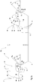
- FIGs 1a-1b and 2 depict a first embodiment of the disclosed vertical joint system 10a.
- Fig 1a shows the joint system 10a as a male part 12 and a female part 14 on opposite sides of a panel P.
- Fig 1b shows the male joint 12 on one panel P1 engaged with the female joint of panel P2 where the panels P1 and P2 are identical to panel P.
- the panels P, P1 and P2 will be hereinafter referred to in general as "panels P".
- Each panel P has an upper surface 16 and an opposite lower surface 18.
- the upper surface 16 may be considered as a top or wear surface of the panel P.
- the lower surface 18 may be considered as the undersurface which would ordinarily face a substrate or other support on which the panels P are laid or otherwise attached.
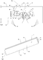
- Figure 2 depicts a rectangular form of the panel P.
- the panel P is formed with opposite longitudinal sides 20 and 22 and opposite transverse sides 24 and 26. Each of the side 20, 22, 24 and 26 is located between the first and lower surfaces 16 and 18.
- the male part 12 may be formed along a first longitudinal side 20 and the female part 14 may be formed along the opposite longitudinal side 22. Additionally, a male part 12 can be formed along the transverse side 24 and a female part 14 can be formed along the opposite transverse side 26.
- the panel P can be formed with a male and female joint on only one side each.
- the male part 12 has a protrusion 28 and an adjacent recess 30.
- the protrusion 28 extends in a direction from the upper surface 16 toward the lower surface 18.
- the recess 30 is formed or extends from the lower surface 18 toward the upper surface 16.
- the male part 12 has an upper edge U from which extends a generally vertical surface 32. This is followed by a generally datum surface 34 and then an outer most (or proximal) male surface 36.
- the datum surface 34 is a planar and horizontal surface.
- the outer most male surface 36 is generally inclined away from the recess 30 in a direction from the upper surface 16 toward the lower surface 18. However the outer most/proximal surface 36 does not extend laterally beyond an upper edge U.
- a lower part of the outer most male surface 36 is formed with a nib 38.
- the outer most male surface 36 is at a front or proximal end of the joint system 10a as it lies on a surface nearest the upper edge U of the panel P in which the joint system is made.
- a bottom surface 37 of the male protrusion is formed with a central concave recess 39 that projects toward the upper surface 16.
- the recess provides a space for foreign material such as: wax or other lubricant which may be placed on surfaces of the joint system 10a; debris produced during manufacture which has not been fully removed; and debris that exists or is generated on site during installation.
- a portion of the male protrusion 28 to the left of the recess 39 which includes the outer most male surface 36 and nib 38 may be considered as forming a nose 41 of the protrusion 28.
- the portions 37 and 47 provide the bottom end of the protrusion 28 with curved or rounded corners.
- the male part 12 is also formed with an inner most (or distal) male surface 40.
- the inner most/distal male surface 40 is at a back or distal end of the joint system 10a as it lies on a surface distant the upper edge U of the panel P in which the joint system 10a is made (or conversely closest to a bottom edge B of the panel P).
- the inner most male surface 40 is formed as a surface of the recess 30.
- Located between the outer most male surface 36 and the inner most male surface 40 is a male common surface 42.
- the male common surface 42 is a surface which is common to both the protrusion 28 and the recess 30.
- the male common surface 42 is formed with a concavity 44. This is followed by a contiguous male planar portion 46.
- the male planar portion 46 lies in a plane perpendicular to that of the surfaces 16 and 18. Additionally the male planar portion 46 is located between the upper surface 16 and the concavity 44.
- a convexly curved surface 47 extends between the concavity 44 and the recess 39.
- the inner most male surface 40 is formed with an undulating profile which forms a first generally convex protuberance 48, a contiguous concave recess 50 and a contiguous second generally convex protuberance 52. After the protuberance 52 the outer most male surface 40 extends to the lower surface 18.
- the female part 14 is formed with a female protrusion 54 and a female recess 56 which is inboard of the protrusion 54.
- the female recess 56 has a surface 58 that depends generally perpendicular from an upper edge U of the upper surface 16 on a side opposite to that of the male part 12. Contiguous with the surface 58 is a concavity 60. The concavity 60 subsequently leads to a datum surface 62 in the recess 56. The datum surface 62 lies parallel to the upper surface 16 and together with the datum surface 34 constitutes a datum plane for the joint system 10a. Thus in an engaged joint system 10 both the datum surfaces 34 and 62 lie in the datum plane. The datum surface acts as a depth control for the insertion of the male part of panel P1 into the female part of panel P2.
- the female part 14 is provided with an inner most female surface 64 that extends to a root of the recess 56.
- the inner most (or proximal) female surface is at a front or proximal end of the joint system 10a as it lies on a surface near an upper edge U of the panel P in which the joint system is made.
- the inner most female surface 64 is formed with a plurality of recesses 66, 68 and 70.
- the recess 70 is closest to the root of the recess 56.
- the female joint 14 is also formed with an outer most (or distal) female surface 72 on a side of the female protrusion 54 distant the recess 56.
- the outer most female surface is at a back or distal end of the joint system 10a as it lies on a surface distant the upper edge U of the panel P in which the joint system is made (or conversely closest to a bottom edge Y of the panel P).
- a female common surface 74 forms part of the surface of both the female recess 56 and the female protrusion 54.
- the outer most female surface 72 is formed with a generally undulating profile and includes a first protuberance 76 followed by a concavity 78 followed by a contiguous second protuberance 80. Contiguous with the second protuberance 80 is a further concavity 82. The concavity 82 then leads to the lower surface 18 and edge Y on the female side.
- the female common surface 74 includes a female generally planar portion 84 followed by a contiguous convex portion 86.
- the female planar portion 84 is located between the convex portion 86 and the lower surface 18.
- the female protrusion 54 has a very slightly curved, indeed almost planar, top surface 87 that is substantially parallel with the upper and lower surfaces 16, 18.
- the portions 86 and 76 provide curved or rounded corners to the upper end of the protrusion 54.
- the inner most (i.e. distal) male surface 40 and the outer most (i.e. distal) female surface 72 can be considered to be a clasping surfaces because when male and female parts 12, 14 of the joint system 10a are engaged these surfaces are able to clasp each other to arrest vertical separation of engaged panels P.
- the location L1 is at a horizontal level marginally below the bottom of the recess 56 and the second location L2 is horizontal level above the bottom of the recess 56.
- the outer most (distal) female surface 72 contacts the inner most male surface 40 at least at the first location L1. This forms the primary vertical lock or arrestment for the joint system.
- vertical lock or arrestment means locking or arresting vertical separation between the engaged panels.
- the surfaces 40 and 72 also contact each other at the second location L2 simultaneously with contact at location L1 so as to also form part of the primary vertical lock or arrestment. But in other embodiments this need not be the case.
- protuberances 76 and 48 may be spaced apart when joined panels P are in the neutral plane but arranged to contact each other when the panels are either (i) under compression in a direction tending to push the surfaces 40 and 72 together, or (ii) relatively rotated as would occur during removal of say panel P1 from panel P2 where panel P1 may be gripped (for example by a suction cup) and pulled upwardly and away from panel P2.
- the inner most (i.e. distal) male surface has a first surface portion with a first tangent plane T1m that is inclined at an angle ⁇ m in the range of about 15° to 75° to a plane parallel to the upper surface.
- the first surface portion is constituted by a surface portion of the generally convex protuberance 52. This surface portion could be either curved or planar. When it is planar (as shown in the embodiment of Fig. 1a and 1b ) then the plane of the surface portion is also parallel with the tangent plane T1.
- the angle ⁇ m may be any angle within the above range for example 15°, or 45° or 75°.
- the angle ⁇ m may be constituted by any sub range within the range of about 15° to 75°, for example 30° to 60°. In this embodiment the angle ⁇ m is 45°.
- the outer most (distal) female surface 72 also has a first surface portion 81 with a first tangent plane T1f that is inclined at the angle ⁇ f .
- the inner most male surface has a first surface portion with a first tangent plane T2m that is inclined at an angle ⁇ m in the range of about 15° to 75° to a plane perpendicular to the upper surface.
- the first surface portion is constituted by a surface portion of the generally convex protuberance 48. This surface portion could be either curved or planar. When it is planar (as shown in the embodiment of Fig. 1a and 1b ) then the plane of the surface portion is also parallel with the tangent plane T2m.
- the angle ⁇ m may be any angle within the range for example 15°, or 45° or 75°. Also the angle ⁇ m may be constituted by any sub range within the range of about 15° to 75°, for example 30° to 60°.
- the outer most female surface also has a first surface portion with a first tangent plane T2f that is inclined at the angle ⁇ f .
- the first surface portion of the outer most female surface is constituted by a surface portion of the generally convex protuberance 76. This surface portion could be either curved or planar. When it is planar (as shown in the embodiment of Fig. 1a and 1b ) then the plane of the surface portion is also or at least is parallel with the tangent plane T2f.
- ⁇ f ⁇ m but more generally ⁇ f ⁇ ⁇ m
- the distal male and female surfaces 40 and 72 in effect provide a primary dual or two stage vertical lock at the back end of the joint when in contact with each other at both locations L1 and L2.
- the second part can be extended to the location L1 when the protuberances 76 and 48 are spaced apart. Further it is believed that in a further embodiment there may be a continuous gap from between where the datum surface 34 contacts the datum surface 62 all the way to the bottom surface 18.
- the male part 12 When the male and female parts are being engaged the male part 12 is first laid on top of a female part 14 so that the protrusion 28 is generally above the recess 56 and the recess 30 is generally above the protrusion 54.
- the convexly curved surface 47 will rest initially on the convexly curved surface 86.
- the planar surface 46 will be substantially parallel with but slightly aback of the planar surface 84.
- the recess 44 passes the convex portion 86 so that the male protrusion 28 now commences lateral motion toward the panel P2 bringing the first male and female surfaces 36 and 64 closer together as well as the male and female engagement surfaces 40 and 72 closer together.
- the downward motion of the male part 12 into the female part 14 is arrested by the datum surface 34 contacting the datum surface 62. This provides depth control resulting in the surfaces 16 of the panels P1 and P2 being co-planar when the panels P1 and P2 are finally fully joined.
- the protuberance 76 sits in the recess 50. Subsequently the protuberance 52 slides over the protuberance 76 and into the recess 78. There after the protuberance 52 engages the protuberance 80 and the protuberance 48 slides under the protuberance 76.
- This provides the primary vertical locking of the joint system 10a.
- the male protrusion 28 sits in the female recess 56 but the proximal male surface 36 is spaced from the proximal female surface 64 at the front end of the joint system. Thus ordinarily the when the joined panels are in the neutral plane and generally unstressed the front end of the joint system 10a does not provide a vertical lock.
- the male and female joints 12 and 14 are being joined while the predominant motion is a vertical motion there is also slight lateral movement toward, away and then again toward each other. This greatly assists in the joining or insertion process.
- the panels provided with the male and female joints 12 and 14 are made from a plastics or composite material such as luxury vinyl tile (LVT), wood plastic composite material (WPC), or other plastics/PVC materials.
- LVT luxury vinyl tile
- WPC wood plastic composite material
- embodiments of the vertical joint system 10 are not limited to such materials.
- other materials from which the panels P may be made include natural timber, manufactured wood, wood laminates, and synthetic materials.
- the male and female parts 12, 14 can be cut, milled, extruded, or molded, or a combination thereof, into the panels P depending on the materials from which they are made and required manufacturing tolerance.
- the surfaces 40 and 72 increase their contact against each other at the second location L2. This is also believed to causes a re-direction of the separating force in a plane perpendicular to the tangent plane T2 tending to close or at least resist the widening of the recess 56.
- joint 10a is designed to be able to be disengaged (for example for the purposes of repair of a floor covering) by application of a force in a direction perpendicular to the upper surface 16 and away from the lower surface 18. This is opposite to the direction of force required for the coupling of the joint system 10a. This is explained later with reference to Figures 7a-7k .
- Figs.1a and 1b shows the adaptability of the present system 10a for surface covering panels P of various thicknesses.
- the system 10a could be used for panels of thickness in the range of, but not limited to say 5mm-7mm.
- the distance AB may be 5mm; AC 5.5mm; AD 6mm; DF 6.5 mm and EF 7mm.
- other thickness ranges are also possible such as 3mm-7mm.
- the joint system 10a has been described above in terms of a male part 12 with a protrusion 28 and recess 30 and a female part 14 with a protrusion 54 and a recess 56.
- the vertical joint system 10a can also be descried in terms of vertically engageable locking parts on at least two opposed sides of a panel P, the locking parts having proximal mutually receivable components near an edge of the upper surface of the panel P in which the vertical joint system 10a is provided, and distal mutually receivable components near an edge of the lower surface of the panel P.
- the proximal mutually receivable components are exemplified by and may have all the features of the male protrusion 28 and the female recess 56 described in relations to all of the presently disclosed embodiments. Both of these components are near the edge of the upper surface 16 of the panel in which the joint system 10a is formed.
- the distal mutually receivable components are exemplified by and may have all the features of the male recess 30 and the female protrusion 54 described in relations to all of the presently disclosed embodiments. Both of these components are near the edge Y of the lower surface 18 of the panel in which the joint system 10a is formed.
- the proximal components being the protrusion 28 and the recess 56 are formed on opposite sides of the same panel P.
- the distal components being the protrusion 54 and the recess 30 are formed on opposite sides of the same panel P.
- proximal and distal mutually receivable components When the joint system 10a is viewed as such proximal and distal mutually receivable components then it is also apparent that the components are configured so that when the respective locking parts of two panels with the same vertical locking system are engaged, the surface 72 on a side of one of the distal components 54 nearest the lower surface 18 overlies a surface 40 on a side of the other distal component 30 nearest the lower surface 18 at a first location L1 and a second location L2. All the full functionality and characteristic of the male and female parts 12, 14 apply to the system 10a when described in terms of the proximal and distal mutually receivable components; including for example the angular relationship between parts of the surfaces at the locations L1 and L2.
- Figure 3 depicts a second embodiment of the vertical joint system 10b.
- the joint system 10b only differs from the joint system 10a in the shape and configuration of the protuberance 80 on the outer most (distal) female surface 72 at the location L1.
- Figure 4 depicts a third embodiment of the vertical joint system 10c.
- the same reference number are used to denote the same feature as in the joint system 10a and 10b; however for ease of distinction features which differ are provided with the suffix "c".
- the joint system 10c only differs from the joint system 10b in:
- Figure 5 depicts a fourth embodiment of the vertical joint system 10d.
- the joint system 10d only differs from the joint system 10a in the relative dimensioning of the protrusion 54 and recess 30 so that at location L2 the protuberances 48 and 76 are spaced apart when the joint is in the neutral plane.
- Figure 6 depicts a fifth embodiment of the vertical joint system 10e.
- the joint system 10e only differs from the joint system 10a in the relative dimensioning of the protrusion 54 and recess 30 so that at locations L1 and L2 the protuberances 48 and 76; and 52 and 80; are spaced apart when the joint is in the neutral plane.
- gravity alone holds the datum surface 34 on the datum surface 62.
- the engaged joint has a small degree of lateral play.
- the embodiment for the joint system 10e differs from the above only in relation to the feature at paragraph (b) where instead for the joint system 10e, at the distal end of the engaged joint the female part overlies the male part in at least one location L1 and/or L2; and there is a continuous gap is formed between the male and female part from the datum plane 62 to the lower surface 18 of the panels P1, P2. Thus there is no contact at L1 or L2 with the embodiment of vertical joint 10e.
- the male and female parts 12, 14 may be configured so that in the engaged joint a continuous gap is formed between the male part 12 and female part 14 from the datum surfaces 34, 62 to where the male part 12 contacts on overlying portion of the female part 14 such as for example at location L1 or L2.
- a continuous gap is formed between the male part 12 and female part 14 from the datum surfaces 34, 62 to where the male part 12 contacts on overlying portion of the female part 14 such as for example at location L1 or L2.
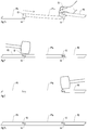
- Figure 7a shows a plan view of a damaged panel P1 in a floor and joined to panels P2, P3, P4, P5, P6 and P7.
- Figures 7b - 7k illustrate a sequence of steps for replacing the damage panel P1 when viewed along section AA of Fig 7a when the panel P1 is made of a plastics or pliable material.
- the panels have the embodiment of the joint system 10a, but irrespective of the specific embodiment of the joint system the sequence of steps remains the same. This sequence is as follows:
- the vertical joint system may be embodied in many other forms.
- the panels P are describes as being of rectangular shape, they may take other polygonal shapes.
- the panels are not limited in use as floor covering panels. They may be used to cover other surfaces such as walls or ceilings.
- the panels can be arranged as a wall covering without needing to be adhered to a wall by first fixing a rail along the top of the wall, fixing a first panel or line of end to end joined panels to the rail then using embodiments of the disclosed joint system to coupled subsequent rows of panels to cover the wall. This produces a suspended wall covering. Avoiding the use of adhesives eliminates damage to the underlying wall in the event that the wall covering is to be subsequently removed or replaced.
- Figure 2 shows an embodiment where the joints system 10 provides male and female parts 12, 14 on each of two sides of the panel so as to form a fully vertically engageable and disengage able surface covering system.
- the joint system 10 may be applied to only two sides and in particular to the short sides 24 and 26, with laterally extending tongue and groove type joints on the other sides 20 and 22. This results in a laydown surface covering system with the joint system 10 providing a "drop lock" on two (usually the short) sides only.
- the panels may be provided with adhesive and preferably a re-stickable adhesive on the lower surface.
- re-stickable adhesive throughout the specification and claims is intended to mean adhesive which is capable of being able to be removed and re-adhered, does not set or cure to a solid rigid mass and maintains long term (e.g. many years) characteristics of flexibility, elasticity and stickiness.
- the characteristic of being re-stickable is intended to mean that the adhesive when applied to a second surface can be subsequently removed by application of a pulling or shearing force and can subsequently be reapplied (for example up to ten times) without substantive reduction in the strength of the subsequent adhesive bond.
- the adhesive provides a removable or non-permanent fixing.
- the characteristics of flexibility and elasticity require that the adhesive does not solidify, harden or cure but rather maintains a degree of flexibility, resilience and elasticity.
- Such adhesives are generally known as fugitive or "booger” glues and pressure sensitive hot melt glues.
- Examples of commercially available adhesives which may be incorporated in embodiments of the present invention includes, but are not limited to: SCOTCH-WELDTM Low Melt Gummy Glue; and GLUE DOTSTM from Glue Dots International of Wisconsin.
- panels particularly those made of plastics or polymer materials, provided with embodiments of the disclosed joint system 10a, 10b may be used as a substrate for another "face" panel such as but not limited to: ceramic tiles; natural stone tiles; metal panels; glass tiles and sheets; fiber cement tiles, boards or panels; and carpet tiles.
- face panels can be permanently fixed to the underlying panels (substrates) to form a laminate product. This enables for example the installation of a floor that has the look and feel of a stone or ceramic tile floor but with the ability to easily replace a damaged tile in the same manner as described above in relation to the floor panels P.
- the face panels may also bear printed or sprayed on coating.
- a metal or fibre cement face panel may have a printed or sprayed on coating or surface decoration.
- a layer of reinforcing material such as a fiber reinforced composite material may be sandwiched between the substrate and the face panel to enhance rigidity.
- a layer of reinforcing material such as a fiber reinforced composite material may be sandwiched between the substrate and the face panel to enhance rigidity.
- the face panel is made of a brittle material such as stone, ceramic or glass to assist in preventing cracking.
- the surfaces 46 and 84 are described in this embodiment as being substantially perpendicular to the upper surface 16. However in other embodiments they may be inclined up to about 20° in the same direction as the angles ⁇ and ⁇ , i.e. so that when inclined the surface 46 overlies the surface 86.
- the ability of the male part 12 to move laterally toward, away from and then again toward an adjoining panel during the insertion process which facilitates ease of insertion may be achieved by in effect reversing the configuration of the male and female common surfaces 42 and 74 so that the convex portion 86 of the female protrusion 54 is replaced by a concave recess similar to the recess 42 while the recess 42 on the male protrusion 28 is in effect filled in so that the concave surface 47 extends continuously to the planar surface 46.
Landscapes
- Engineering & Computer Science (AREA)
- Architecture (AREA)
- Civil Engineering (AREA)
- Structural Engineering (AREA)
- Finishing Walls (AREA)
- Floor Finish (AREA)
- Hinges (AREA)
- Building Awnings And Sunshades (AREA)
Claims (13)
- Système de joint vertical (10a-d) pour un panneau de couverture de surface (P) présentant une surface supérieure (16) qui est visible lorsque la couverture de surface est posée et une surface inférieure opposée (18) et plusieurs côtés (20, 22, 24, 26) disposés entre les surfaces supérieure et inférieure (16, 18), le système de joint vertical comprenant :une partie mâle (12) le long d'un premier des côtés (20/24) ;une partie femelle (14) le long d'un second des côtés (22/26), le second côté étant opposé au premier côté ;la partie femelle (14) présentant une protubérance (54) qui s'étend à partir de la surface inférieure (18) vers la surface supérieure (16) et une surface femelle extérieure (72) sur la protubérance (54),la partie mâle (12) présentant un creux (30) qui s'ouvre sur la surface inférieure (18), une portion du creux (30) formant une surface mâle intérieure (40) ;dans lequel la surface femelle extérieure (72) et la surface mâle intérieure (40) sont disposées de sorte que lorsque la partie mâle (12) d'un panneau de couverture de surface (P) est enclenchée avec une partie femelle (14) d'un second panneau de couverture de surface (P) la surface femelle extérieure (72) recouvre la surface mâle intérieure (40) à un premier endroit (L1) et un second endroit (L2) ; caractérisé en ce quela partie femelle (14) présente une surface de référence (62) sur laquelle la partie mâle porte lorsque les parties mâle et femelle de systèmes de joints verticaux respectifs sont disposées, la surface de référence (62) fournissant un contrôle de profondeur pour la partie mâle (12) lorsqu'elle est insérée dans la partie femelle (14), eten ce qu'un écartement continu s'étend entre (a) la partie mâle et la partie femelle à partir de la surface de référence (62) jusqu'au second endroit (L2) ; ou (b) la partie mâle et la partie femelle à partir de la surface de référence (62) jusqu'au premier endroit (L1).
- Système de joint vertical selon la revendication 1, dans lequel dans au moins un des premier et second endroits (L1, L2) la surface femelle extérieure (72) et la surface mâle intérieure (40) se touchent l'une l'autre lorsque les surfaces inférieures (18) de deux panneaux semblables joints (P) se trouvent dans un plan commun.
- Système de joint vertical selon la revendication 2, dans lequel la surface femelle extérieure (72) et la surface mâle intérieure (40) se touchent l'une l'autre au premier endroit (L1) et dans lequel le premier endroit (L1) est plus proche de la surface inférieure (18) que le second endroit (L2).
- Système de joint vertical selon l'une quelconque des revendications 1 à 3, dans lequel le second endroit (L2) surplombe le premier endroit (L1).
- Système de joint vertical selon l'une quelconque des revendications 1 à 4, dans lequel la surface mâle intérieure (72) au premier endroit (L1) présente une première portion de surface avec un premier plan tangent (T1m) sur une première région de contact avec la surface femelle extérieure (40) qui est inclinée à un angle θm° dans l'intervalle d'environ 15° à 75° par rapport à un plan parallèle à la surface supérieure, et est de préférence d'environ 45.
- Système de joint vertical selon la revendication 5, dans lequel la première portion de surface est une de : une portion de surface d'une protubérance généralement convexe ; et une portion de surface plane.
- Système de joint vertical selon l'une quelconque des revendications 4 à 6, dans lequel la surface femelle externe adjacente à la première région de contact et sur le côté le plus proche de la surface de fond est en général inclinée à un angle θf° ≤ θm°.
- Système de joint vertical selon la revendication 7, dans lequel l'angle θf° est d'environ 15° par rapport au plan parallèle à la surface supérieure.
- Système de joint vertical selon l'une quelconque des revendications 1 à 8, dans lequel la surface mâle intérieure (72) au second endroit (L2) présente une seconde portion de surface avec un second plan tangent sur une seconde région de contact avec la surface femelle extérieure (40) qui est inclinée à un angle βm° dans l'intervalle d'environ 15° à 75° par rapport à un plan parallèle à la surface supérieure, et de préférence l'angle βm° est d'environ 45°.
- Système de joint vertical selon la revendication 9, dans lequel au second endroit la surface femelle extérieure sur la seconde région de contact avec la surface mâle intérieure présente une portion de surface se trouvant dans le second plan tangent.
- Système de joint vertical selon l'une quelconque des revendications 1 à 10, dans lequel : la partie mâle (12) présente une protubérance mâle (28) adjacente au creux mâle (30) avec une surface mâle extérieure (36) formée sur la protubérance mâle (28) distante du creux mâle (30) ; la partie femelle (14) présente un creux femelle (56) adjacent à la protubérance femelle (54), dans lequel le creux femelle (56) présente une surface femelle intérieure (64) distante de la protubérance femelle (54) ; et dans lequel la surface femelle intérieure (64) recouvre la surface mâle extérieure (36).
- Système de joint vertical selon la revendication 11, dans lequel la surface femelle intérieure (64) est munie d'une série de creux contigus et la surface mâle extérieure (36) est munie d'un talon (38) ; la surface femelle intérieure et la surface mâle extérieure sont configurées de sorte que lorsque la partie mâle (12) est totalement enclenchée avec la partie femelle (14) le talon (38) réside dans le creux le plus bas des creux contigus ; et configurées de sorte qu'en réponse à une rotation relative ou un soulèvement de la partie mâle par rapport à la partie femelle le talon (38) peut entrer dans des creux plus élevés respectifs successivement pour fournir une résistance au retrait de la protubérance mâle du creux femelle.
- Système de joint vertical selon l'une quelconque des revendications 1 à 12, dans lequel les parties mâle et femelle sont configurées pour se toucher l'une l'autre lorsqu'elles sont enclenchées à l'un ou les deux des premier et second endroits de manière à presser les surfaces de référence ensemble.
Priority Applications (3)
| Application Number | Priority Date | Filing Date | Title |
|---|---|---|---|
| EP19182019.0A EP3567184B1 (fr) | 2014-08-29 | 2015-08-31 | Système de joint vertical pour panneau de revêtement de surface |
| EP22215312.4A EP4219860A1 (fr) | 2014-08-29 | 2015-08-31 | Système de joint vertical pour panneau de revêtement de surface |
| PL15835947T PL3186459T3 (pl) | 2014-08-29 | 2015-08-31 | Układ pionowego złącza dla panelu pokrywającego powierzchnię |
Applications Claiming Priority (2)
| Application Number | Priority Date | Filing Date | Title |
|---|---|---|---|
| AU2014903452A AU2014903452A0 (en) | 2014-08-29 | Vertical Joint System for a Surface Covering Panel | |
| PCT/AU2015/000531 WO2016029255A1 (fr) | 2014-08-29 | 2015-08-31 | Système de joint vertical pour un panneau de recouvrement de surface |
Related Child Applications (2)
| Application Number | Title | Priority Date | Filing Date |
|---|---|---|---|
| EP22215312.4A Division EP4219860A1 (fr) | 2014-08-29 | 2015-08-31 | Système de joint vertical pour panneau de revêtement de surface |
| EP19182019.0A Division EP3567184B1 (fr) | 2014-08-29 | 2015-08-31 | Système de joint vertical pour panneau de revêtement de surface |
Publications (3)
| Publication Number | Publication Date |
|---|---|
| EP3186459A1 EP3186459A1 (fr) | 2017-07-05 |
| EP3186459A4 EP3186459A4 (fr) | 2018-02-14 |
| EP3186459B1 true EP3186459B1 (fr) | 2019-06-26 |
Family
ID=55398492
Family Applications (3)
| Application Number | Title | Priority Date | Filing Date |
|---|---|---|---|
| EP19182019.0A Active EP3567184B1 (fr) | 2014-08-29 | 2015-08-31 | Système de joint vertical pour panneau de revêtement de surface |
| EP22215312.4A Pending EP4219860A1 (fr) | 2014-08-29 | 2015-08-31 | Système de joint vertical pour panneau de revêtement de surface |
| EP15835947.1A Active EP3186459B1 (fr) | 2014-08-29 | 2015-08-31 | Système de joint vertical pour un panneau de recouvrement de surface |
Family Applications Before (2)
| Application Number | Title | Priority Date | Filing Date |
|---|---|---|---|
| EP19182019.0A Active EP3567184B1 (fr) | 2014-08-29 | 2015-08-31 | Système de joint vertical pour panneau de revêtement de surface |
| EP22215312.4A Pending EP4219860A1 (fr) | 2014-08-29 | 2015-08-31 | Système de joint vertical pour panneau de revêtement de surface |
Country Status (10)
| Country | Link |
|---|---|
| US (5) | US10316526B2 (fr) |
| EP (3) | EP3567184B1 (fr) |
| AU (1) | AU2015309679B2 (fr) |
| CA (1) | CA2996422C (fr) |
| ES (1) | ES2939189T3 (fr) |
| HR (1) | HRP20230136T1 (fr) |
| HU (1) | HUE061045T2 (fr) |
| PL (2) | PL3567184T3 (fr) |
| PT (1) | PT3567184T (fr) |
| WO (1) | WO2016029255A1 (fr) |
Families Citing this family (37)
| Publication number | Priority date | Publication date | Assignee | Title |
|---|---|---|---|---|
| US7763345B2 (en) | 1999-12-14 | 2010-07-27 | Mannington Mills, Inc. | Thermoplastic planks and methods for making the same |
| US8028486B2 (en) | 2001-07-27 | 2011-10-04 | Valinge Innovation Ab | Floor panel with sealing means |
| SE530653C2 (sv) | 2006-01-12 | 2008-07-29 | Vaelinge Innovation Ab | Fuktsäker golvskiva samt golv med ett elastiskt ytskikt omfattande ett dekorativt spår |
| EP2473687B1 (fr) | 2009-09-04 | 2019-04-24 | Välinge Innovation AB | Procédé d'assemblage de lames de parquet souples qui sont équipées d'un système de verrouillage mécanique |
| US8365499B2 (en) | 2009-09-04 | 2013-02-05 | Valinge Innovation Ab | Resilient floor |
| US11725395B2 (en) | 2009-09-04 | 2023-08-15 | Välinge Innovation AB | Resilient floor |
| EP4092213B1 (fr) * | 2010-01-11 | 2023-12-13 | Välinge Innovation AB | Revêtement de sol avec conception d'interverrouillage |
| PT3358101T (pt) | 2013-03-25 | 2020-01-21 | Vaelinge Innovation Ab | Tábuas de piso providas de um sistema de bloqueio mecânico e método para produzir um sistema de bloqueio deste tipo |
| HRP20241390T1 (hr) | 2014-07-16 | 2024-12-20 | Välinge Innovation AB | Postupak proizvodnje termoplastične folije otporne na habanje |
| US10316526B2 (en) * | 2014-08-29 | 2019-06-11 | Valinge Innovation Ab | Vertical joint system for a surface covering panel |
| PL4379167T3 (pl) | 2014-09-26 | 2026-02-09 | Unilin, Bv | Panel podłogowy do tworzenia pokrycia podłogowego |
| NO3031998T3 (fr) | 2014-12-08 | 2018-02-24 | ||
| KR102469131B1 (ko) | 2015-01-14 | 2022-11-18 | 뵈린게 이노베이션 에이비이 | 상이한 광택 레벨들을 갖는 내마모성 층을 제조하는 방법 |
| WO2017105335A1 (fr) | 2015-12-17 | 2017-06-22 | Välinge Innovation AB | Procédé de production d'un système de verrouillage mécanique destiné à des panneaux |
| CN106088527A (zh) * | 2016-07-07 | 2016-11-09 | 安徽国风木塑科技有限公司 | 一种挂扣式中空木塑地板 |
| US10287777B2 (en) | 2016-09-30 | 2019-05-14 | Valinge Innovation Ab | Set of panels |
| NL2019609B1 (en) | 2017-09-22 | 2019-03-28 | Innovations4Flooring Holding N V | Panel and covering |
| WO2019081016A1 (fr) * | 2017-10-25 | 2019-05-02 | Xylo Technologies Ag | Système de revêtement de sol à flexibilité améliorée |
| HRP20230520T1 (hr) | 2018-01-09 | 2023-08-04 | Välinge Innovation AB | Skup ploča |
| NL2020256B1 (en) | 2018-01-09 | 2019-07-15 | Innovations4Flooring Holding N V | Panel |
| EP3581732B1 (fr) * | 2018-06-15 | 2022-12-07 | Akzenta Paneele + Profile GmbH | Panneau avec rainure et baguette étanchéifiante |
| NL2021886B1 (en) * | 2018-10-26 | 2020-05-13 | I4F Licensing Nv | Panel, in particular a floor panel or wall panel, and panel covering |
| NL2021885B1 (en) * | 2018-10-26 | 2020-05-13 | I4F Licensing Nv | Multi-purpose tile system, tile covering, and tile |
| NL2022114B1 (en) * | 2018-12-03 | 2020-06-30 | I4F Licensing Nv | Decorative panel, and decorative floor covering consisting of said panels |
| AU2019426795B2 (en) * | 2019-01-30 | 2025-04-24 | I4F Licensing Nv | A flooring panel and a floor covering with such panel |
| WO2020159355A1 (fr) * | 2019-01-30 | 2020-08-06 | Floor Locking Technology B.V. | Panneau et revêtement le comprenant |
| EP3918150B1 (fr) * | 2019-01-30 | 2024-12-18 | I4F Licensing Nv | Panneau et revêtement de sol comprenant ledit panneau |
| BE1027299B1 (nl) * | 2019-05-22 | 2020-12-22 | Flooring Ind Ltd Sarl | Vloerpaneel voor het vormen van een vloerbekleding |
| BE1027634B1 (nl) | 2019-10-08 | 2021-05-06 | Flooring Ind Ltd Sarl | Vloerpaneel voor het vormen van een vloerbekleding |
| EP4560089A3 (fr) | 2019-12-03 | 2025-11-05 | Unilin, BV | Panneau de plancher pour former un revêtement de sol |
| LU101663B1 (en) * | 2020-03-06 | 2021-09-14 | Tarkett Gdl Sa | Set of surface covering planks and method of connecting thereof |
| US12392140B2 (en) * | 2020-07-31 | 2025-08-19 | I4F Licensing Nv | Panel and covering |
| CA3184199A1 (fr) * | 2020-07-31 | 2022-02-03 | I4F Licensing Nv | Panneau, revetement et procede de decouplage de deux panneaux interconnectes |
| FR3131593B1 (fr) | 2021-12-31 | 2024-01-05 | Gerflor | Panneau de revêtement de sol ou mur à résistance accrue au désassemblage |
| DE202022102571U1 (de) | 2022-05-11 | 2023-08-17 | Lignum Technologies Ag | Fußbodensystem mit verbesserter Widerstandsfähigkeit gegenüber Feuchtigkeitseinwirkung |
| US20250277372A1 (en) * | 2023-01-11 | 2025-09-04 | "Barlinek" Spólka Akcyjna | Set of floor panels |
| WO2025061270A1 (fr) | 2023-09-19 | 2025-03-27 | Clyx Bv | Système d'accouplement double face pour panneaux de plancher réversibles |
Family Cites Families (337)
| Publication number | Priority date | Publication date | Assignee | Title |
|---|---|---|---|---|
| US1787027A (en) | 1929-02-20 | 1930-12-30 | Wasleff Alex | Herringbone flooring |
| US3120083A (en) | 1960-04-04 | 1964-02-04 | Bigelow Sanford Inc | Carpet or floor tiles |
| FR1293043A (fr) | 1961-03-27 | 1962-05-11 | Piraud Plastiques Ets | Carreau de revêtement de sol |
| US3247638A (en) | 1963-05-22 | 1966-04-26 | James W Fair | Interlocking tile carpet |
| US3538665A (en) | 1968-04-15 | 1970-11-10 | Bauwerke Ag | Parquet flooring |
| SE515210C2 (sv) * | 2000-04-10 | 2001-06-25 | Valinge Aluminium Ab | Låssystem för hopfogning av golvskivor samt golvskivor försedda med sådana låssystem och golv bildat av sådana golvskivor |
| SE0002342L (sv) | 2000-06-22 | 2001-07-16 | Tarkett Sommer Ab | Golvbräda med kopplingsorgan |
| US3760547A (en) | 1969-08-13 | 1973-09-25 | J Brenneman | Spline and seat connector assemblies |
| CH526974A (de) | 1970-02-20 | 1972-08-31 | Bruun & Soerensen | Fussboden zum Auflegen auf eine Eisbahn |
| US3694983A (en) | 1970-05-19 | 1972-10-03 | Pierre Jean Couquet | Pile or plastic tiles for flooring and like applications |
| GB1385375A (en) | 1971-02-26 | 1975-02-26 | Sanwa Kako Co | Floor covering unit |
| DE2111324C3 (de) | 1971-03-10 | 1979-07-05 | Migua-Mitteldeutsche Gummi Und Asbestgesellschaft Hammerschmidt & Co, 5628 Heiligenhaus | Vorrichtung zum Dichten von Fugen zwischen Bauteilen |
| DE2251762A1 (de) | 1972-10-21 | 1974-05-02 | Geb Walter Gisela Weber | Fussbodenbelag |
| GB1430423A (en) | 1973-05-09 | 1976-03-31 | Gkn Sankey Ltd | Joint structure |
| US3919820A (en) | 1973-12-13 | 1975-11-18 | Johns Manville | Wall structure and device for sealing thereof |
| US4172169A (en) | 1976-10-01 | 1979-10-23 | Nairn Floors Limited | Floor or wall coverings |
| US4113399A (en) | 1977-03-02 | 1978-09-12 | Hansen Sr Wray C | Knob spring |
| US4176210A (en) | 1977-04-12 | 1979-11-27 | Gaf Corporation | Process for making urethane coated decorative sheet-type covering material |
| ES230786Y (es) | 1977-08-27 | 1978-03-16 | Junta para paneles de tejado. | |
| US4180615A (en) | 1977-11-07 | 1979-12-25 | Gaf Corporation | Vinyl tile and production thereof |
| US4187131A (en) | 1978-02-21 | 1980-02-05 | Congoleum Corporation | Resinous polymer sheet materials having selective, surface decorative effects and methods of making the same |
| US4313866A (en) | 1978-12-26 | 1982-02-02 | Monsanto Company | Plasticizers for vinyl chloride polymers |
| US4426820A (en) | 1979-04-24 | 1984-01-24 | Heinz Terbrack | Panel for a composite surface and a method of assembling same |
| US4333987A (en) | 1979-12-19 | 1982-06-08 | Harold Kwart | Methods for bonding dissimilar synthetic polymeric materials and the products involved in and resulting from such methods |
| US4423178A (en) | 1980-05-19 | 1983-12-27 | Monsanto Company | Plasticizers for vinyl chloride polymers |
| US4393187A (en) | 1982-06-23 | 1983-07-12 | Congoleum Corporation | Stain resistant, abrasion resistant polyurethane coating composition, substrate coated therewith and production thereof |
| US4489115A (en) | 1983-02-16 | 1984-12-18 | Superturf, Inc. | Synthetic turf seam system |
| DK149498C (da) | 1983-04-07 | 1986-12-01 | Inter Ikea As | Beklaedning af braedder til f.eks. gulve eller paneler |
| US4512131A (en) | 1983-10-03 | 1985-04-23 | Laramore Larry W | Plank-type building system |
| US4507188A (en) | 1983-12-21 | 1985-03-26 | Thiokol Corporation | Ultraviolet curable formulations containing urethane acrylate monomers |
| US4614680A (en) | 1984-04-16 | 1986-09-30 | Armstrong World Industries, Inc. | Decorative product |
| JPS60255843A (ja) | 1984-05-31 | 1985-12-17 | Toyo Linoleum Mfg Co Ltd:The | ビニルタイル |
| DK155616C (da) | 1984-09-25 | 1989-09-04 | Eminent Plast | Rist- eller maatteelement til dannelse af en gulvbeklaedning ved sammenkobling med lignende elementer |
| IT1183846B (it) | 1985-05-20 | 1987-10-22 | Mondo Rubber Spa | Rivestimento di materiale sintetico in forma di piastrelle e relativo procedimento di fabbricazione |
| DE3622602A1 (de) | 1986-07-05 | 1988-01-14 | Basf Ag | Bindemittel fuer den transferdruck |
| US5007222A (en) | 1988-11-14 | 1991-04-16 | Raymond Harry W | Foamed building panel including an internally mounted stud |
| US5112671A (en) | 1989-04-13 | 1992-05-12 | Armstrong World Industries, Inc. | Tile product having multiple levels of height, multiple levels of gloss and mortar-line surround |
| US5148850A (en) | 1989-06-28 | 1992-09-22 | Paneltech Ltd. | Weatherproof continuous hinge connector for articulated vehicular overhead doors |
| US5162141A (en) | 1990-12-17 | 1992-11-10 | Armstrong World Industries, Inc. | Polymeric sheet having an incompatible ink permanently bonded thereto |
| US5182892A (en) | 1991-08-15 | 1993-02-02 | Louisiana-Pacific Corporation | Tongue and groove board product |
| US5458953A (en) | 1991-09-12 | 1995-10-17 | Mannington Mills, Inc. | Resilient floor covering and method of making same |
| US5344700A (en) | 1992-03-27 | 1994-09-06 | Aliquot, Ltd. | Structural panels and joint connector arrangement therefor |
| US7121059B2 (en) | 1994-04-29 | 2006-10-17 | Valinge Innovation Ab | System for joining building panels |
| US7086205B2 (en) | 1993-05-10 | 2006-08-08 | Valinge Aluminium Ab | System for joining building panels |
| SE501014C2 (sv) | 1993-05-10 | 1994-10-17 | Tony Pervan | Fog för tunna flytande hårda golv |
| JPH0748879A (ja) | 1993-08-05 | 1995-02-21 | Takeshige Shimonohara | 部材の接合方法及び接合構造 |
| US5441677A (en) | 1993-09-01 | 1995-08-15 | Hi-Tech Floors, Inc. | Method of making high gloss, hardened concrete floors |
| US5380794A (en) | 1993-11-02 | 1995-01-10 | Monsanto Company | Polyvinyl butyral tackifier for vinyl chloride polymer compositions |
| KR960005785B1 (ko) | 1993-12-08 | 1996-05-01 | 주식회사두발가스 엔지니어링 | 열교환기의 가열관 |
| JP3363976B2 (ja) | 1993-12-24 | 2003-01-08 | ミサワホーム株式会社 | 床材の施工構造 |
| JP3461569B2 (ja) | 1994-05-02 | 2003-10-27 | 大建工業株式会社 | 床 材 |
| US5465546A (en) | 1994-05-04 | 1995-11-14 | Buse; Dale C. | Portable dance floor |
| KR0147425B1 (ko) | 1994-07-07 | 1998-11-02 | 김주용 | 티이오에스 공정장치 |
| JP3167866B2 (ja) | 1994-09-02 | 2001-05-21 | ミサワホーム株式会社 | フローリング材の床面形成構造 |
| US7131242B2 (en) | 1995-03-07 | 2006-11-07 | Pergo (Europe) Ab | Flooring panel or wall panel and use thereof |
| SE9500810D0 (sv) | 1995-03-07 | 1995-03-07 | Perstorp Flooring Ab | Golvplatta |
| US5618602A (en) | 1995-03-22 | 1997-04-08 | Wilsonart Int Inc | Articles with tongue and groove joint and method of making such a joint |
| US5670237A (en) | 1995-06-07 | 1997-09-23 | Mannington Mills, Inc. | Method for making a surface covering product and products resulting from said method |
| US5630304A (en) | 1995-12-28 | 1997-05-20 | Austin; John | Adjustable interlock floor tile |
| JP3954673B2 (ja) | 1996-11-01 | 2007-08-08 | 株式会社ヤマックス | コンクリート製接合物の止水用接合部材 |
| BE1010487A6 (nl) | 1996-06-11 | 1998-10-06 | Unilin Beheer Bv | Vloerbekleding bestaande uit harde vloerpanelen en werkwijze voor het vervaardigen van dergelijke vloerpanelen. |
| US5950389A (en) | 1996-07-02 | 1999-09-14 | Porter; William H. | Splines for joining panels |
| WO1998017357A1 (fr) | 1996-10-18 | 1998-04-30 | Variform Oy | Structure de protection |
| US5694730A (en) | 1996-10-25 | 1997-12-09 | Noranda Inc. | Spline for joining boards |
| US6291078B1 (en) | 1997-10-22 | 2001-09-18 | Mannington Mills, Inc. | Surface coverings containing aluminum oxide |
| US5797237A (en) | 1997-02-28 | 1998-08-25 | Standard Plywoods, Incorporated | Flooring system |
| AT405560B (de) | 1997-06-18 | 1999-09-27 | Kaindl M | Anordnung mit bauteilen und bauteile |
| IT237576Y1 (it) | 1997-07-11 | 2000-09-13 | Unifor Spa | Sistema di collegamento perfezionato tra pannelli componibili |
| US6345481B1 (en) | 1997-11-25 | 2002-02-12 | Premark Rwp Holdings, Inc. | Article with interlocking edges and covering product prepared therefrom |
| US6324809B1 (en) | 1997-11-25 | 2001-12-04 | Premark Rwp Holdings, Inc. | Article with interlocking edges and covering product prepared therefrom |
| US6139945A (en) | 1997-11-25 | 2000-10-31 | Premark Rwp Holdings, Inc. | Polymeric foam substrate and its use as in combination with decorative surfaces |
| DE19854475B4 (de) | 1997-11-25 | 2006-06-14 | Premark RWP Holdings, Inc., Wilmington | Verriegelndes Flächenabdeckungserzeugnis |
| US6173548B1 (en) | 1998-05-20 | 2001-01-16 | Douglas J. Hamar | Portable multi-section activity floor and method of manufacture and installation |
| US7386963B2 (en) | 1998-06-03 | 2008-06-17 | Valinge Innovation Ab | Locking system and flooring board |
| SE512290C2 (sv) | 1998-06-03 | 2000-02-28 | Valinge Aluminium Ab | Låssystem för mekanisk hopfogning av golvskivor samt golvskiva försedd med låssystemet |
| BE1012141A6 (nl) | 1998-07-24 | 2000-05-02 | Unilin Beheer Bv | Vloerbekleding, vloerpaneel daarvoor en werkwijze voor het realiseren van dergelijk vloerpaneel. |
| SE515789C2 (sv) | 1999-02-10 | 2001-10-08 | Perstorp Flooring Ab | Golvbeläggningsmaterial innefattande golvelement vilka är avsedda att sammanfogas vertikalt |
| SE514645C2 (sv) | 1998-10-06 | 2001-03-26 | Perstorp Flooring Ab | Golvbeläggningsmaterial innefattande skivformiga golvelement avsedda att sammanfogas av separata sammanfogningsprofiler |
| DE19851200C1 (de) | 1998-11-06 | 2000-03-30 | Kronotex Gmbh Holz Und Kunstha | Fußbodenpaneele |
| FR2785633B1 (fr) | 1998-11-09 | 2001-02-09 | Valerie Roy | Panneau de recouvrement pour parquet, lambris ou analogue |
| FI982525A0 (fi) | 1998-11-23 | 1998-11-23 | Variform Oy | Suojausjärjestely |
| SE517478C2 (sv) | 1999-04-30 | 2002-06-11 | Valinge Aluminium Ab | Låssystem för mekanisk hofogning av golvskivor, golvskiva försedd med låssystemet samt metod för framställning av mekaniskt hopfogningsbara golvskivor |
| IT1311220B1 (it) | 1999-04-20 | 2002-03-04 | Patt Srl | Pavimento a doghe e metodo per la sua posa in opera |
| US6233899B1 (en) | 1999-05-21 | 2001-05-22 | David N. Nystrom | Apparatus and methods for installing tongue-and-groove materials |
| WO2001000948A1 (fr) | 1999-06-24 | 2001-01-04 | Flexiteek International A/S | Revetement de surface pouvant epouser la forme de cette surface |
| US7896571B1 (en) | 1999-06-30 | 2011-03-01 | Akzenta Paneele + Profile Gmbh | Panel and panel fastening system |
| DE29911462U1 (de) | 1999-07-02 | 1999-11-18 | Akzenta Paneele & Profile Gmbh | Befestigungssystem für Paneele |
| SE517009C2 (sv) | 1999-07-05 | 2002-04-02 | Perstorp Flooring Ab | Golvelement med styrdon |
| US7614197B2 (en) | 1999-11-08 | 2009-11-10 | Premark Rwp Holdings, Inc. | Laminate flooring |
| US7169460B1 (en) | 1999-12-14 | 2007-01-30 | Mannington Mills, Inc. | Thermoplastic planks and methods for making the same |
| US6761008B2 (en) | 1999-12-14 | 2004-07-13 | Mannington Mills, Inc. | Connecting system for surface coverings |
| US7763345B2 (en) | 1999-12-14 | 2010-07-27 | Mannington Mills, Inc. | Thermoplastic planks and methods for making the same |
| US6617009B1 (en) | 1999-12-14 | 2003-09-09 | Mannington Mills, Inc. | Thermoplastic planks and methods for making the same |
| US6939496B2 (en) | 1999-12-20 | 2005-09-06 | Psa Composites, Llc | Method and apparatus for forming composite material and composite material therefrom |
| AU4743800A (en) | 1999-12-23 | 2001-07-09 | Hamberger Industriewerke Gmbh | Joint |
| US6332733B1 (en) | 1999-12-23 | 2001-12-25 | Hamberger Industriewerke Gmbh | Joint |
| US7337588B1 (en) | 1999-12-27 | 2008-03-04 | Maik Moebus | Panel with slip-on profile |
| DE10001076C1 (de) | 2000-01-13 | 2001-10-04 | Huelsta Werke Huels Kg | Paneelelement |
| US6399670B1 (en) | 2000-01-21 | 2002-06-04 | Congoleum Corporation | Coating having macroscopic texture and process for making same |
| SE517183C2 (sv) | 2000-01-24 | 2002-04-23 | Valinge Aluminium Ab | Låssystem för mekanisk hopfogning av golvskivor, golvskiva försedd med låssystemet och metod för framställning av sådana golvskivor |
| SE522860C2 (sv) | 2000-03-10 | 2004-03-09 | Pergo Europ Ab | Vertikalt förenade golvelement innefattande en kombination av olika golvelement |
| SE518184C2 (sv) * | 2000-03-31 | 2002-09-03 | Perstorp Flooring Ab | Golvbeläggningsmaterial innefattande skivformiga golvelement vilka sammanfogas med hjälp av sammankopplingsorgan |
| US6363677B1 (en) | 2000-04-10 | 2002-04-02 | Mannington Mills, Inc. | Surface covering system and methods of installing same |
| US6553724B1 (en) | 2000-05-05 | 2003-04-29 | Robert A. Bigler | Panel and trade show booth made therefrom |
| DE20008708U1 (de) * | 2000-05-16 | 2000-09-14 | Kronospan Technical Co. Ltd., Nikosia | Paneele mit Kupplungsmitteln |
| BE1013569A3 (nl) | 2000-06-20 | 2002-04-02 | Unilin Beheer Bv | Vloerbekleding. |
| DE10031639C2 (de) | 2000-06-29 | 2002-08-14 | Hw Ind Gmbh & Co Kg | Fussbodenplatte |
| US6546691B2 (en) | 2000-12-13 | 2003-04-15 | Kronospan Technical Company Ltd. | Method of laying panels |
| DE10064280C1 (de) | 2000-12-22 | 2002-10-10 | Huelsta Werke Huels Kg | Platte für den Innenausbau sowie Verfahren zum Erstellen von neuen Wänden eines Raumes oder zur Verkleidung von vorhandenen Flächen eines Raumes |
| US20030110720A1 (en) | 2000-12-22 | 2003-06-19 | Berard Raymond A. | Padded raised flooring panels and coverings |
| US6851241B2 (en) | 2001-01-12 | 2005-02-08 | Valinge Aluminium Ab | Floorboards and methods for production and installation thereof |
| US6769218B2 (en) | 2001-01-12 | 2004-08-03 | Valinge Aluminium Ab | Floorboard and locking system therefor |
| DE10101912C1 (de) | 2001-01-16 | 2002-03-14 | Johannes Schulte | Verfahren zum Verlegen von in der Konfiguration rechteckigen Bodenpaneelen |
| DE20109840U1 (de) | 2001-06-17 | 2001-09-06 | Kronospan Technical Co. Ltd., Nikosia | Platten mit Einschiebe-Steckprofil |
| US20020189183A1 (en) | 2001-06-19 | 2002-12-19 | Ricciardelli Thomas E. | Decorative interlocking tile |
| US20040211144A1 (en) | 2001-06-27 | 2004-10-28 | Stanchfield Oliver O. | Flooring panel or wall panel and use thereof |
| US6823638B2 (en) | 2001-06-27 | 2004-11-30 | Pergo (Europe) Ab | High friction joint, and interlocking joints for forming a generally planar surface, and method of assembling the same |
| EP1277896A1 (fr) | 2001-07-16 | 2003-01-22 | Ulf Palmberg | Planches de plancher |
| SE519791C2 (sv) | 2001-07-27 | 2003-04-08 | Valinge Aluminium Ab | System för bildande av en fog mellan två golvskivor, golvskivor därför försedd med tätningsorgan vid fogkanterna samt sätt att tillverka en kärna som bearbetas till golvskivor |
| US8028486B2 (en) | 2001-07-27 | 2011-10-04 | Valinge Innovation Ab | Floor panel with sealing means |
| DE20122778U1 (de) * | 2001-08-10 | 2007-10-25 | Akzenta Paneele + Profile Gmbh | Paneel sowie Befestigungssystem für Paneele |
| BE1014345A3 (nl) | 2001-08-14 | 2003-09-02 | Unilin Beheer Bv | Vloerpaneel en werkwijze voor het vervaardigen ervan. |
| SE525558C2 (sv) | 2001-09-20 | 2005-03-08 | Vaelinge Innovation Ab | System för bildande av en golvbeläggning, sats av golvskivor samt förfarande för tillverkning av två olika typer av golvskivor |
| US8250825B2 (en) | 2001-09-20 | 2012-08-28 | Välinge Innovation AB | Flooring and method for laying and manufacturing the same |
| US20040243595A1 (en) | 2001-09-28 | 2004-12-02 | Zhan Cui | Database management system |
| DE10151614C1 (de) | 2001-10-23 | 2003-04-24 | Kaindl Wals M | Paneel mit schallverbessernder Schicht nebst Herstellungsverfahren |
| EP1308577A3 (fr) | 2001-10-31 | 2003-10-15 | E.F.P. Floor Products Fussböden GmbH | Système de plancher avec une pluralité de panneaux |
| FR2832470B1 (fr) | 2001-11-21 | 2006-10-20 | Grosfillex Sarl | Dispositif de lame profilee |
| DE10159284B4 (de) | 2001-12-04 | 2005-04-21 | Kronotec Ag | Gebäudeplatte, insbesondere Bodenpaneel |
| FR2833487B1 (fr) | 2001-12-18 | 2004-08-27 | Oreal | Compositions cosmetiques comprenant des polymeres a fonctions chimiques complementaires |
| DE20203311U1 (de) * | 2002-03-01 | 2002-05-08 | hülsta-werke Hüls GmbH & Co. KG, 48703 Stadtlohn | Paneelelement |
| JP4472355B2 (ja) | 2002-04-03 | 2010-06-02 | ベーリンゲ、イノベイション、アクチボラグ | フロアボード用機械式係止システム |
| DE10214972A1 (de) | 2002-04-04 | 2003-10-30 | Akzenta Paneele & Profile Gmbh | Paneel sowie Verriegelungssystem für Paneele |
| DE50311595D1 (de) | 2002-04-05 | 2009-07-30 | Tilo Gmbh | Fussbodendielen |
| SE525657C2 (sv) | 2002-04-08 | 2005-03-29 | Vaelinge Innovation Ab | Golvskivor för flytande golv framställda av åtminstone två olika materialskikt samt halvfabrikat för tillverkning av golvskivor |
| US7051486B2 (en) | 2002-04-15 | 2006-05-30 | Valinge Aluminium Ab | Mechanical locking system for floating floor |
| US7739849B2 (en) | 2002-04-22 | 2010-06-22 | Valinge Innovation Ab | Floorboards, flooring systems and methods for manufacturing and installation thereof |
| KR20050007372A (ko) | 2002-05-03 | 2005-01-17 | 디에스엠 아이피 어셋츠 비.브이. | 방사선 경화성 수지 조성물 및 이를 이용한 쾌속 성형법 |
| DE20207844U1 (de) | 2002-05-16 | 2002-08-22 | ANKER-Teppichboden Gebr. Schoeller GmbH + Co.KG, 52353 Düren | Teppichbodenbelagselement |
| DE10233731A1 (de) | 2002-07-24 | 2004-04-08 | M. Kaindl | Anordnung von Bauteilen mit Verbindungselementen |
| US6794001B2 (en) | 2002-07-25 | 2004-09-21 | Mannington Mills, Inc. | Flooring with a 2-part adhesive |
| US20040031225A1 (en) | 2002-08-14 | 2004-02-19 | Gregory Fowler | Water resistant tongue and groove flooring |
| AT413228B (de) | 2002-08-19 | 2005-12-15 | Kaindl M | Verkleidungsplatte |
| DE10243196B4 (de) | 2002-09-18 | 2007-03-22 | Kaindl Flooring Gmbh | Paneele mit Verbindungsklammer |
| SE525630C2 (sv) | 2002-11-13 | 2005-03-22 | Kaehr Ab G | Golvskiva och golvbeläggning för fjädrande golv |
| AU2003275757A1 (en) | 2002-11-13 | 2004-06-03 | Ab Gustaf Kahr | Floorboard and floor covering for resilient floor |
| DE50309830D1 (de) | 2002-11-15 | 2008-06-26 | Flooring Technologies Ltd | Einrichtung bestehend aus zwei miteinander verbindbaren Bauplatten und einem Einsatz zum Verriegeln dieser Bauplatten |
| DE10318093A1 (de) | 2002-12-02 | 2004-06-17 | Kronospan Ag | Verfahren zur Beleimung eines Elements |
| SE525622C2 (sv) | 2002-12-09 | 2005-03-22 | Pergo Europ Ab | Förfarande för installation av paneler med foganordningar, inkapslat medel och lim |
| DE20219110U1 (de) | 2002-12-09 | 2003-03-13 | Kronospan Technical Company Ltd., Engomi, Nikosia | Paneele mit Kabelkanal |
| WO2004063491A1 (fr) | 2003-01-08 | 2004-07-29 | Flooring Industries Ltd. | Dalle de sol, procedes de pose et de fabrication associes |
| US20040206036A1 (en) | 2003-02-24 | 2004-10-21 | Valinge Aluminium Ab | Floorboard and method for manufacturing thereof |
| US7677001B2 (en) | 2003-03-06 | 2010-03-16 | Valinge Innovation Ab | Flooring systems and methods for installation |
| US7845140B2 (en) | 2003-03-06 | 2010-12-07 | Valinge Innovation Ab | Flooring and method for installation and manufacturing thereof |
| SE0300642D0 (sv) | 2003-03-11 | 2003-03-11 | Pergo Europ Ab | Process for sealing a joint |
| DE20304761U1 (de) | 2003-03-24 | 2004-04-08 | Kronotec Ag | Einrichtung zum Verbinden von Bauplatten, insbesondere Bodenpaneele |
| US7442423B2 (en) | 2003-04-28 | 2008-10-28 | Shaw Industries Group | Hard surface-veneer engineered surfacing tiles |
| US7550192B2 (en) | 2003-04-30 | 2009-06-23 | Congoleum Corporation | Resilient floor tile |
| BE1015760A6 (nl) | 2003-06-04 | 2005-08-02 | Flooring Ind Ltd | Vloerpaneel en werkwijze voor het vervaardigen van dergelijk vloerpaneel. |
| US7090430B1 (en) | 2003-06-23 | 2006-08-15 | Ground Floor Systems, Llc | Roll-up surface, system and method |
| US20050021081A1 (en) | 2003-07-24 | 2005-01-27 | Clozex Medical, Llc | Device for laceration or incision closure |
| KR100566083B1 (ko) * | 2003-08-07 | 2006-03-30 | 주식회사 한솔홈데코 | 조립식 바닥재 |
| US20050079780A1 (en) | 2003-10-14 | 2005-04-14 | Rowe Richard E. | Fiber wear layer for resilient flooring and other products |
| US20050112320A1 (en) | 2003-11-20 | 2005-05-26 | Wright Jeffery J. | Carpet structure with plastomeric foam backing |
| US7886497B2 (en) | 2003-12-02 | 2011-02-15 | Valinge Innovation Ab | Floorboard, system and method for forming a flooring, and a flooring formed thereof |
| US20050144881A1 (en) | 2003-12-18 | 2005-07-07 | Pergo (Europe) Ab | Molding and flooring material |
| US7516588B2 (en) | 2004-01-13 | 2009-04-14 | Valinge Aluminium Ab | Floor covering and locking systems |
| DE602004007469T2 (de) | 2004-01-13 | 2008-03-13 | Berry Finance Nv | Teppichfliesen |
| SE526596C2 (sv) | 2004-01-13 | 2005-10-11 | Vaelinge Innovation Ab | Flytande golv med mekanisk låssystem som möjliggör rörelse mellan golvskivorna |
| DE202004001037U1 (de) | 2004-01-24 | 2004-04-29 | Kronotec Ag | Paneel, insbesondere Fussbodenpaneel |
| DE102004011531C5 (de) | 2004-03-08 | 2014-03-06 | Kronotec Ag | Holzwerkstoffplatte, insbesondere Fußbodenpaneel |
| DE102004012582A1 (de) | 2004-03-12 | 2005-10-06 | Hülsta-Werke Hüls Gmbh & Co. Kg | Paneelelement |
| DE102004028757B4 (de) | 2004-04-02 | 2007-11-15 | hülsta-werke Hüls GmbH & Co. KG. | Paneelelement zur Boden-, Wand- und/oder Deckenverlegung sowie Verfahren zum Verlegen eines Belages, insbesondere eines Boden-, Wand- und/oder Deckenbelages |
| US20050221073A1 (en) | 2004-04-02 | 2005-10-06 | Der-Lin Liou | Elastomeric foam article |
| US20050247000A1 (en) | 2004-05-04 | 2005-11-10 | Zhu Sai Y | Interlocking self-aligning cladding panel for floors, walls, ceilings, or the like |
| US7342080B2 (en) | 2004-05-07 | 2008-03-11 | 3M Innovative Properties Company | Polymerizable compositions, methods of making the same, and composite articles therefrom |
| KR100612211B1 (ko) | 2004-07-06 | 2006-08-16 | 삼성전자주식회사 | 릴레이 기록후 자동으로 하나의 타이틀을 만드는광기록재생장치 및 그 방법 |
| WO2006033706A1 (fr) | 2004-07-30 | 2006-03-30 | Mannington Mills, Inc. | Produits pour sol et procedes de fabrication associes |
| US7861483B2 (en) | 2004-09-17 | 2011-01-04 | Dirk Dammers | Floor panel with the tongue more elastic than the locking element |
| DE202004015275U1 (de) | 2004-09-17 | 2005-05-04 | Hdm Gmbh | Paneel, insbesondere Fußbodenpaneel |
| ATE481537T1 (de) | 2004-10-05 | 2010-10-15 | Nicolaas Albertus Heyns | Trägerelement, modulares fliesenelement, system von verriegelungsmechanismen und verfahren zum verlegen von fliesen |
| US7454875B2 (en) | 2004-10-22 | 2008-11-25 | Valinge Aluminium Ab | Mechanical locking system for floor panels |
| US7841144B2 (en) | 2005-03-30 | 2010-11-30 | Valinge Innovation Ab | Mechanical locking system for panels and method of installing same |
| SI1650375T2 (sl) | 2004-10-22 | 2011-04-29 | Vaelinge Innovation Ab | Set talnih panelov |
| DE202004021867U1 (de) | 2004-10-22 | 2011-12-27 | Välinge Innovation AB | Mechanische Verriegelung für Bodenpaneele |
| US7607271B2 (en) | 2004-11-09 | 2009-10-27 | Johns Manville | Prefabricated multi-layer roofing panel and system |
| US20060156666A1 (en) | 2005-01-20 | 2006-07-20 | Caufield Francis J | Synthetic boards for exterior water-resistant applications |
| US8215078B2 (en) | 2005-02-15 | 2012-07-10 | Välinge Innovation Belgium BVBA | Building panel with compressed edges and method of making same |
| DE202005004537U1 (de) | 2005-03-17 | 2005-06-16 | Schulte, Johannes | Paneele für Fußboden-, Wand- oder Deckenbeläge |
| US20130139478A1 (en) | 2005-03-31 | 2013-06-06 | Flooring Industries Limited, Sarl | Methods for packaging floor panels, as well as packed set of floor panels |
| BE1016938A6 (nl) * | 2005-03-31 | 2007-10-02 | Flooring Ind Ltd | Werkwijzen voor het vervaardigen en verpakken van vloerpanelen, inrichtingen hierbij aangewend, alsmede vloerpaneel en verpakte set van vloerpanelen. |
| US8061104B2 (en) | 2005-05-20 | 2011-11-22 | Valinge Innovation Ab | Mechanical locking system for floor panels |
| US20060260252A1 (en) * | 2005-05-23 | 2006-11-23 | Quality Craft Ltd. | Connection for laminate flooring |
| DE102005028072B4 (de) * | 2005-06-16 | 2010-12-30 | Akzenta Paneele + Profile Gmbh | Fußbodenpaneel |
| SE529076C2 (sv) | 2005-07-11 | 2007-04-24 | Pergo Europ Ab | En fog till paneler |
| DE102005061099A1 (de) | 2005-07-25 | 2007-03-29 | Hipper, August, Dipl.-Ing. (FH) | Leimlose Verbindung für Plattenelemente, im speziellen für Fußbodenpaneele |
| US7849655B2 (en) | 2005-07-27 | 2010-12-14 | Mannington Mills, Inc. | Connecting system for surface coverings |
| CA2618188A1 (fr) | 2005-08-08 | 2007-02-15 | Kronospan Technical Company Ltd. | Profile de dilatation affleurant |
| DE102005059540A1 (de) | 2005-08-19 | 2007-06-14 | Bauer, Jörg R. | Lösbar aneinander zu befestigende, flächige Bauteile, sowie Bauteil |
| CA2520434C (fr) | 2005-09-20 | 2013-01-08 | Covermaster Inc. | Couverture protectrice de surface polyvalente |
| US20070130872A1 (en) | 2005-12-08 | 2007-06-14 | Goodwin Milton W | Wide width lock and fold laminate |
| US7905070B2 (en) | 2005-12-21 | 2011-03-15 | John August | Interlocking mortarless structural concrete block building system |
| US7155871B1 (en) | 2005-12-29 | 2007-01-02 | Tru Woods Limited | Floor plank |
| US20070151189A1 (en) | 2006-01-03 | 2007-07-05 | Feng-Ling Yang | Securing device for combining floor plates |
| SE530653C2 (sv) | 2006-01-12 | 2008-07-29 | Vaelinge Innovation Ab | Fuktsäker golvskiva samt golv med ett elastiskt ytskikt omfattande ett dekorativt spår |
| US8464489B2 (en) | 2006-01-12 | 2013-06-18 | Valinge Innovation Ab | Laminate floor panels |
| DE102006011887A1 (de) | 2006-01-13 | 2007-07-19 | Akzenta Paneele + Profile Gmbh | Sperrelement, Paneel mit separatem Sperrelement, Verfahren zur Installation eines Paneelbelags aus Paneelen mit Sperrelementen sowie Verfahren und Vorrichtung zur Vormontage eines Sperrelements an einem Paneel |
| DE102006006124A1 (de) | 2006-02-10 | 2007-08-23 | Flooring Technologies Ltd. | Einrichtung zum Verriegeln zweier Bauplatten |
| GB2436082B (en) | 2006-03-17 | 2011-02-23 | Visul Systems Ltd | Tactile tiling |
| BE1017049A6 (nl) | 2006-04-06 | 2007-12-04 | Flooring Ind Ltd | Werkwijze voor het vervaardigen van vloerpanelen en vloerpaneel. |
| WO2007115379A1 (fr) | 2006-04-12 | 2007-10-18 | James Hardie International Finance B.V. | Element de construction renforce a surface etanche |
| DK2009197T3 (en) | 2006-04-14 | 2016-06-13 | Yekalon Ind Inc | Floor block, floor system and laying method therefore |
| DE102006024184A1 (de) | 2006-05-23 | 2007-11-29 | Hipper, August, Dipl.-Ing. (FH) | Verbindung für Plattenpaneele |
| US20070275207A1 (en) | 2006-05-24 | 2007-11-29 | Higgins Kenneth B | Carpet tile and related methods |
| GB0613583D0 (en) | 2006-07-05 | 2006-08-16 | Sericol Ltd | A printing ink |
| SE533410C2 (sv) | 2006-07-11 | 2010-09-14 | Vaelinge Innovation Ab | Golvpaneler med mekaniska låssystem med en flexibel och förskjutbar tunga samt tunga därför |
| US7678215B2 (en) | 2006-07-11 | 2010-03-16 | Allied Industries International Inc. | Installation method for non-slip sanitary flooring |
| US7861482B2 (en) | 2006-07-14 | 2011-01-04 | Valinge Innovation Ab | Locking system comprising a combination lock for panels |
| SE531110C2 (sv) | 2006-07-14 | 2008-12-23 | Vaelinge Innovation Ab | Låssystem omfattande ett kombinationslås för paneler |
| BE1017350A6 (nl) | 2006-10-31 | 2008-06-03 | Flooring Ind Ltd | Vloerpaneel en vloerbekleding bestaande uit dergelijke vloerpanelen. |
| US8689512B2 (en) | 2006-11-15 | 2014-04-08 | Valinge Innovation Ab | Mechanical locking of floor panels with vertical folding |
| DE102006057491A1 (de) | 2006-12-06 | 2008-06-12 | Akzenta Paneele + Profile Gmbh | Paneel sowie Bodenbelag |
| SE531111C2 (sv) | 2006-12-08 | 2008-12-23 | Vaelinge Innovation Ab | Mekanisk låsning av golvpaneler |
| DE102006058655B4 (de) | 2006-12-11 | 2010-01-21 | Ulrich Windmöller Consulting GmbH | Bodenpaneel |
| US8728603B2 (en) | 2006-12-11 | 2014-05-20 | Ulrich Windmöller Consulting GmbH | Floor panel |
| US20080153609A1 (en) | 2006-12-20 | 2008-06-26 | Daniel Kotler | Outdoor sports floor system |
| BE1017403A5 (nl) | 2006-12-21 | 2008-08-05 | Flooring Ind Ltd | Vloerelement, vergrendelingsysteem voor vloerelementen, vloerbekleding en werkwijze voor het samenstellen van dergelijke vloerelementen tot een vloerbekleding. |
| US7984600B2 (en) | 2007-02-02 | 2011-07-26 | Mohawk Carpet Corporation | Groutless tile system and method for making the same |
| DE102007015048B4 (de) | 2007-03-26 | 2009-03-05 | Kronotec Ag | Paneel, insbesondere Bodenpaneel |
| WO2008133377A1 (fr) | 2007-04-27 | 2008-11-06 | Easywood, Inc. | Lame de parquet présentant des surfaces renforcées |
| KR100870496B1 (ko) | 2007-04-27 | 2008-11-25 | 주식회사 이지테크 | 수직 시공 가능한 바닥마감용 마루판재 |
| CN101532331A (zh) | 2007-07-30 | 2009-09-16 | 诺瓦利斯股份有限公司 | 具有互锁设计的地板覆盖物 |
| DE102007042840B4 (de) | 2007-09-10 | 2010-04-22 | Flooring Technologies Ltd. | Paneel, insbesondere Bodenpaneel |
| US8945702B2 (en) | 2007-10-31 | 2015-02-03 | Bemis Company, Inc. | Barrier packaging webs having metallized non-oriented film |
| US8353140B2 (en) | 2007-11-07 | 2013-01-15 | Valinge Innovation Ab | Mechanical locking of floor panels with vertical snap folding |
| WO2009061279A1 (fr) | 2007-11-07 | 2009-05-14 | Välinge Innovation AB | Blocage mécanique de panneaux de sol avec encliquetage sur pliure verticale et procédé d'installation pour relier ces panneaux |
| FR2924274B1 (fr) | 2007-11-22 | 2012-11-30 | Saint Gobain | Substrat porteur d'une electrode, dispositif electroluminescent organique l'incorporant, et sa fabrication |
| GB2455096B (en) * | 2007-11-27 | 2011-11-02 | Cambridge Display Tech Ltd | Organic thin film transistors and methods of making the same |
| US7805903B2 (en) | 2007-12-13 | 2010-10-05 | Liu David C | Locking mechanism for flooring boards |
| US7861753B2 (en) | 2007-12-20 | 2011-01-04 | Mannington Mills, Inc. | Dual-edge irregular bevel-cut system and method |
| US7883425B2 (en) | 2008-01-23 | 2011-02-08 | Disney Enterprises, Inc. | Flooring system |
| EP2235285B1 (fr) | 2008-01-31 | 2019-06-26 | Välinge Innovation AB | Bloqueur mécanique de panneaux de sol |
| US8505257B2 (en) | 2008-01-31 | 2013-08-13 | Valinge Innovation Ab | Mechanical locking of floor panels |
| US20090223162A1 (en) | 2008-03-05 | 2009-09-10 | Mannington Mills, Inc. | Connecting System For Surface Coverings |
| CA2715730A1 (fr) | 2008-03-06 | 2009-09-11 | Mary Katherine Dyczko-Riglin | Revetements de surface contenant un materiau vct regenere, et procedes et systemes pour leur fabrication et leur utilisation |
| US20090235604A1 (en) | 2008-03-20 | 2009-09-24 | Xxentria Technology Materials Co., Ltd | Architectural material |
| TW201004791A (en) | 2008-07-16 | 2010-02-01 | Xxentria Technology Materials Co Ltd | A composite board material assembly |
| DE202008010555U1 (de) | 2008-08-08 | 2009-12-17 | Akzenta Paneele + Profile Gmbh | Kunststoffpaneel mit Hakenprofil |
| US8037656B2 (en) * | 2008-08-08 | 2011-10-18 | Liu David C | Flooring boards with press down locking mechanism |
| DE202008011589U1 (de) | 2008-09-01 | 2008-11-27 | Akzenta Paneele + Profile Gmbh | Fußbodenpaneel aus Kunststoff mit mechanischen Verriegelungskanten |
| DE202008012001U1 (de) | 2008-09-09 | 2008-11-27 | Akzenta Paneele + Profile Gmbh | Fußbodenpaneel mit einer Trägerschicht aus Kunststoff |
| CN101492950B (zh) | 2008-09-10 | 2011-01-12 | 滁州扬子木业有限公司 | 带有锁合装置的地板 |
| US8166718B2 (en) | 2008-10-10 | 2012-05-01 | Liu David C | Horizontally engineered hardwood floor and method of installation |
| BE1018382A3 (nl) * | 2008-12-22 | 2010-09-07 | Wybo Carlos | Bekledingspaneel. |
| EP2208835B1 (fr) | 2009-01-16 | 2012-05-30 | Flooring Technologies Ltd. | Panneau, en particulier panneau de sol |
| ES2383934T3 (es) | 2009-01-28 | 2012-06-27 | Flooring Technologies Ltd. | Panel, en particular panel de suelo |
| PL2226447T3 (pl) | 2009-02-27 | 2012-10-31 | Vaelinge Innovation Ab | Panel, zwłaszcza panel podłogowy |
| KR100958396B1 (ko) | 2009-03-31 | 2010-05-18 | 오광석 | 바닥재 |
| DE102009019492A1 (de) | 2009-05-04 | 2010-11-11 | Akzenta Paneele + Profile Gmbh | Verriegelungssystem für Paneele |
| NL2003019C2 (nl) * | 2009-06-12 | 2010-12-15 | 4Sight Innovation Bv | Vloerpaneel en vloerbedekking bestaande uit meerdere van dergelijke vloerpanelen. |
| US9885149B2 (en) | 2009-07-08 | 2018-02-06 | Dow Global Technologies Llc | Carpet and carpet backing |
| DE102009034903B3 (de) | 2009-07-27 | 2011-01-20 | Guido Schulte | Belag aus mechanisch miteinander verbindbaren Paneelen |
| DE102009034902B4 (de) | 2009-07-27 | 2015-10-01 | Guido Schulte | Belag aus mechanisch miteinander verbindbaren Paneelen |
| EP2473687B1 (fr) | 2009-09-04 | 2019-04-24 | Välinge Innovation AB | Procédé d'assemblage de lames de parquet souples qui sont équipées d'un système de verrouillage mécanique |
| US8365499B2 (en) | 2009-09-04 | 2013-02-05 | Valinge Innovation Ab | Resilient floor |
| DE102009041297B4 (de) | 2009-09-15 | 2018-10-11 | Guido Schulte | Belag aus mechanisch miteinander verbindbaren Elementen und ein Verfahren zur Herstellung von Elementen |
| DE102009048050B3 (de) | 2009-10-02 | 2011-01-20 | Guido Schulte | Belag aus mechanischen miteinander verbindbaren Elementen |
| EP2501763A4 (fr) | 2009-11-18 | 2014-01-01 | 3M Innovative Properties Co | Revêtements protecteurs et procédés de fabrication et d'utilisation associés |
| CN102652201B (zh) | 2009-12-17 | 2014-11-12 | 瓦林格创新股份有限公司 | 与建筑镶板的表面成形相关的方法和设备 |
| PT2339092T (pt) | 2009-12-22 | 2019-07-19 | Flooring Ind Ltd Sarl | Método para produzir painéis de cobertura |
| EP4092213B1 (fr) | 2010-01-11 | 2023-12-13 | Välinge Innovation AB | Revêtement de sol avec conception d'interverrouillage |
| DE102010004717A1 (de) | 2010-01-15 | 2011-07-21 | Pergo (Europe) Ab | Set aus Paneelen umfassend Halteprofile mit einem separaten Clip sowie Verfahren zum Einbringen des Clips |
| WO2011092478A2 (fr) | 2010-01-28 | 2011-08-04 | Derek Whitaker | Revêtement de surface incorporant une jointure à verrouillage |
| DE102010012572B3 (de) * | 2010-03-23 | 2011-07-14 | Fritz Egger Gmbh & Co. Og | System von wenigstens zwei Paneelen |
| US8480841B2 (en) | 2010-04-13 | 2013-07-09 | Ceralog Innovation Belgium BVBA | Powder overlay |
| EP2588685B1 (fr) | 2010-06-30 | 2020-08-05 | Kreafin Group SA | Panneau avec moyens d'accouplement améliorés |
| EP2423410B1 (fr) | 2010-08-27 | 2013-02-13 | Barlinek S.A. | Panneau de construction doté de moyens de verrouillage améliorés pour la liaison amovible de panneaux de construction similaires |
| EP2657428B1 (fr) | 2010-10-20 | 2018-08-08 | Kronoplus Technical AG | Revêtement de surface comprenant des panneaux stratifiés et un élément de verrouillage étranger |
| DE202010015754U1 (de) | 2010-11-23 | 2011-01-20 | Akzenta Paneele + Profile Gmbh | Fußbodenpaneel mit weichelastischer Nutzschicht |
| DE102010063976B4 (de) | 2010-12-22 | 2013-01-17 | Akzenta Paneele + Profile Gmbh | Paneel |
| DE202011110452U1 (de) | 2011-01-28 | 2014-02-11 | Akzenta Paneele + Profile Gmbh | Paneel |
| CN102155083B (zh) * | 2011-01-29 | 2014-07-23 | 刘谦益 | 一种地板连接结构 |
| SG193535A1 (en) | 2011-03-18 | 2013-10-30 | Inotec Internat Pty Ltd | Vertical joint system and associated surface covering system |
| US8806832B2 (en) | 2011-03-18 | 2014-08-19 | Inotec Global Limited | Vertical joint system and associated surface covering system |
| WO2012136021A1 (fr) | 2011-04-03 | 2012-10-11 | Ge Yuejin | Plaque de plancher à verrouillage en poly(chlorure de vinyle) |
| KR101119611B1 (ko) | 2011-06-01 | 2012-03-06 | 주식회사 대진 | 체결 시공되는 데코타일 |
| US8631622B2 (en) | 2011-07-07 | 2014-01-21 | Chinafloors Holding Limited | Non-squeaking wood flooring systems and methods |
| US20130025964A1 (en) | 2011-07-27 | 2013-01-31 | Armstrong World Industries, Inc. | Sound reducing tongue and groove member sound reducing fabrication process and sound reducing blend |
| US8600629B2 (en) * | 2011-07-28 | 2013-12-03 | Ag Leader Technology | Compensation method for planter shut off delay |
| DE102012102339A1 (de) | 2011-07-29 | 2013-01-31 | Hamberger Industriewerke Gmbh | Verbindung für elastische oder plattenförmige Bauelemente, Profilschieber und Fußbodenbelag |
| DE102012105793A1 (de) | 2011-07-29 | 2013-01-31 | Hamberger Industriewerke Gmbh | Verbindung für elastische oder plattenförmige Bauelemente und Fußbodenbelag |
| US8590252B2 (en) | 2011-08-15 | 2013-11-26 | Eurico Januario Cordeiro | Groutless tile system |
| US8763340B2 (en) | 2011-08-15 | 2014-07-01 | Valinge Flooring Technology Ab | Mechanical locking system for floor panels |
| US8769905B2 (en) | 2011-08-15 | 2014-07-08 | Valinge Flooring Technology Ab | Mechanical locking system for floor panels |
| PT3115161T (pt) | 2011-08-29 | 2020-02-06 | Ceraloc Innovation Ab | Sistema de encaixe mecânico para painéis de pavimento |
| WO2013044377A1 (fr) | 2011-09-28 | 2013-04-04 | Distribution Duroy Inc. | Panneau de couverture et procédé d'assemblage d'une pluralité de panneaux de couverture |
| CN102392519B (zh) | 2011-09-30 | 2015-08-19 | 张家铭 | 按压扣合式锁扣板材及扣合方法 |
| WO2013050910A2 (fr) | 2011-10-03 | 2013-04-11 | Unilin, Bvba | Panneau et procédé de fabrication de panneaux |
| DE102011121348A1 (de) | 2011-12-19 | 2013-06-20 | Fritz Egger Gmbh & Co. Og | Paneel eines Fußbodenbelags mit einer entlang einer Seitenkante geneigten Verriegelungsfläche |
| BE1020433A3 (nl) * | 2012-01-05 | 2013-10-01 | Flooring Ind Ltd Sarl | Paneel. |
| US20130174507A1 (en) | 2012-01-11 | 2013-07-11 | Advent Inc. | Flooring System |
| BE1022209B1 (nl) | 2012-01-12 | 2016-03-01 | I.V.C. N.V. | Vloerpaneel |
| KR102149416B1 (ko) | 2012-04-04 | 2020-08-28 | 뵈린게 이노베이션 에이비이 | 빌딩 패널용 기계식 잠금 시스템의 제조 방법 |
| WO2013181379A1 (fr) | 2012-05-30 | 2013-12-05 | Interfacial Solutions Ip, Llc | Composites polymères, panneaux résultants et leur procédé de production |
| RS60954B1 (sr) | 2012-06-19 | 2020-11-30 | Vaelinge Innovation Ab | Sistem mehaničkog zaključavanja podnih dasaka |
| KR102238758B1 (ko) | 2012-07-02 | 2021-04-08 | 세라록 이노베이션 에이비 | 중량 및 재료 함량이 감소된, 건축용 패널, 플로어 패널 및 목재 기반 플로어 패널의 생산 방법 |
| WO2014033628A1 (fr) * | 2012-08-27 | 2014-03-06 | Pergo (Europe) Ab | Panneau |
| CN104870726B (zh) | 2012-09-19 | 2017-11-07 | 依诺泰克环球有限公司 | 饰面板材及相关锁扣系统 |
| CN104968873B (zh) * | 2013-01-11 | 2018-03-27 | 地板工业有限公司 | 用于形成地板覆层的地板镶板,由这种地板镶板形成的地板覆层以及制造这种地板镶板的方法 |
| PT3358101T (pt) | 2013-03-25 | 2020-01-21 | Vaelinge Innovation Ab | Tábuas de piso providas de um sistema de bloqueio mecânico e método para produzir um sistema de bloqueio deste tipo |
| BE1021833B1 (nl) | 2013-05-30 | 2016-01-21 | Flooring Industries Limited Sarl | Paneel |
| HUE060779T2 (hu) | 2013-06-27 | 2023-04-28 | Vaelinge Innovation Ab | Mechanikus rögzítõrendszerrel ellátott építõpanel |
| WO2015070890A1 (fr) | 2013-11-12 | 2015-05-21 | Grigorij Wagner | Élément de revêtement de sol |
| DE102013113130B4 (de) | 2013-11-27 | 2022-01-27 | Välinge Innovation AB | Verfahren zur Herstellung einer Fußbodendiele |
| DE202015009485U1 (de) | 2014-01-09 | 2017-12-01 | Flooring Industries Limited, Sarl | Fußbodenpaneel zur Bildung eines Fußbodenbelags |
| EP2915934A1 (fr) | 2014-03-06 | 2015-09-09 | Flooring Industries Ltd., SARL. | Kit de panneaux avec élément de verrouillage |
| US9260870B2 (en) | 2014-03-24 | 2016-02-16 | Ivc N.V. | Set of mutually lockable panels |
| ES2822958T3 (es) | 2014-04-10 | 2021-05-05 | Berryalloc Nv | Tablero de piso con sistema de conexión universal |
| KR102386246B1 (ko) | 2014-05-14 | 2022-04-12 | 뵈린게 이노베이션 에이비이 | 기계식 록킹 시스템이 구비된 빌딩 패널 |
| HRP20241390T1 (hr) | 2014-07-16 | 2024-12-20 | Välinge Innovation AB | Postupak proizvodnje termoplastične folije otporne na habanje |
| US10081952B2 (en) | 2014-08-13 | 2018-09-25 | Resilite Sports Products, Inc. | System and method for interlocking sections of athletic and/or protective surface mats |
| US10316526B2 (en) | 2014-08-29 | 2019-06-11 | Valinge Innovation Ab | Vertical joint system for a surface covering panel |
| NL2013486B1 (en) | 2014-09-18 | 2016-09-28 | Champion Link Int Corp | Panel suitable for assembling a waterproof floor or wall covering, method of producing a panel. |
| US9249582B1 (en) | 2014-11-14 | 2016-02-02 | Awi Licensing Company | Interlocking floor panels with high performance locking profiles |
| ES2768959T3 (es) | 2014-12-22 | 2020-06-24 | Ceraloc Innovation Ab | Conjunto de paneles de suelo idénticos dotados de un sistema de bloqueo mecánico |
| US9650792B2 (en) | 2014-12-23 | 2017-05-16 | Afi Licensing Llc | Interlocking floor panels and floor system |
| KR102469131B1 (ko) | 2015-01-14 | 2022-11-18 | 뵈린게 이노베이션 에이비이 | 상이한 광택 레벨들을 갖는 내마모성 층을 제조하는 방법 |
| WO2016113706A1 (fr) | 2015-01-15 | 2016-07-21 | Flooring Industries Limited, Sarl | Panneau de sol pour former un revêtement de sol |
| EP3245354B1 (fr) | 2015-01-16 | 2026-04-15 | Unilin BV | Panneau de plancher pour la formation d'un revêtement de sol |
| DE102015121761A1 (de) | 2015-12-14 | 2017-06-14 | Guido Schulte | Mechanische Verbindung für Paneele |
| WO2017105335A1 (fr) | 2015-12-17 | 2017-06-22 | Välinge Innovation AB | Procédé de production d'un système de verrouillage mécanique destiné à des panneaux |
| US10648182B2 (en) | 2015-12-31 | 2020-05-12 | Flooring Industries Limited, Sarl | Floor panel for forming a floor covering |
| BE1023779B1 (nl) | 2015-12-31 | 2017-07-24 | Flooring Industries Limited Sarl | Vloerpaneel voor het vormen van een vloerbekleding |
| WO2017187298A2 (fr) | 2016-04-25 | 2017-11-02 | Flooring Industries Limited, Sarl | Ensemble de panneaux de plancher et procédé d'installation dudit ensemble de panneaux de plancher |
| BE1024157B1 (nl) | 2016-04-25 | 2017-11-24 | Flooring Industries Limited, Sarl | Set van vloerpanelen en werkwijze voor het installeren van deze set van vloerpanelen. |
| US10287777B2 (en) | 2016-09-30 | 2019-05-14 | Valinge Innovation Ab | Set of panels |
| HRP20230520T1 (hr) | 2018-01-09 | 2023-08-04 | Välinge Innovation AB | Skup ploča |
-
2015
- 2015-08-31 US US15/507,602 patent/US10316526B2/en active Active
- 2015-08-31 WO PCT/AU2015/000531 patent/WO2016029255A1/fr not_active Ceased
- 2015-08-31 PL PL19182019.0T patent/PL3567184T3/pl unknown
- 2015-08-31 PT PT191820190T patent/PT3567184T/pt unknown
- 2015-08-31 PL PL15835947T patent/PL3186459T3/pl unknown
- 2015-08-31 HU HUE19182019A patent/HUE061045T2/hu unknown
- 2015-08-31 EP EP19182019.0A patent/EP3567184B1/fr active Active
- 2015-08-31 ES ES19182019T patent/ES2939189T3/es active Active
- 2015-08-31 EP EP22215312.4A patent/EP4219860A1/fr active Pending
- 2015-08-31 AU AU2015309679A patent/AU2015309679B2/en active Active
- 2015-08-31 CA CA2996422A patent/CA2996422C/fr active Active
- 2015-08-31 HR HRP20230136TT patent/HRP20230136T1/hr unknown
- 2015-08-31 EP EP15835947.1A patent/EP3186459B1/fr active Active
-
2019
- 2019-04-24 US US16/392,931 patent/US10982449B2/en active Active
- 2019-11-29 US US16/699,297 patent/US10865571B2/en active Active
-
2020
- 2020-11-10 US US17/094,226 patent/US11661749B2/en active Active
-
2023
- 2023-04-18 US US18/302,566 patent/US20230349167A1/en active Pending
Non-Patent Citations (1)
| Title |
|---|
| None * |
Also Published As
| Publication number | Publication date |
|---|---|
| PL3567184T3 (pl) | 2023-03-20 |
| EP3567184A1 (fr) | 2019-11-13 |
| US10865571B2 (en) | 2020-12-15 |
| US20170241136A1 (en) | 2017-08-24 |
| EP3567184B1 (fr) | 2022-12-28 |
| CA2996422A1 (fr) | 2016-03-03 |
| US11661749B2 (en) | 2023-05-30 |
| HUE061045T2 (hu) | 2023-05-28 |
| ES2939189T3 (es) | 2023-04-19 |
| AU2015309679A1 (en) | 2017-04-20 |
| US20190249444A1 (en) | 2019-08-15 |
| US20200208409A1 (en) | 2020-07-02 |
| EP4219860A1 (fr) | 2023-08-02 |
| US20210214953A1 (en) | 2021-07-15 |
| US20230349167A1 (en) | 2023-11-02 |
| HRP20230136T1 (hr) | 2023-03-31 |
| PL3186459T3 (pl) | 2019-11-29 |
| US10982449B2 (en) | 2021-04-20 |
| PT3567184T (pt) | 2023-03-06 |
| WO2016029255A1 (fr) | 2016-03-03 |
| EP3186459A1 (fr) | 2017-07-05 |
| EP3186459A4 (fr) | 2018-02-14 |
| AU2015309679B2 (en) | 2020-01-16 |
| CA2996422C (fr) | 2023-05-02 |
| US10316526B2 (en) | 2019-06-11 |
Similar Documents
| Publication | Publication Date | Title |
|---|---|---|
| US20230349167A1 (en) | Vertical joint system for a surface covering panel | |
| US12286801B2 (en) | Set of mutually lockable panels | |
| CA2840714C (fr) | Systeme de verrouillage mecanique pour panneaux de plancher | |
| US9260870B2 (en) | Set of mutually lockable panels | |
| EP3299539B1 (fr) | Panneaux de construction munis d'un système de verrouillage mécanique | |
| EP3615745B1 (fr) | Panneau et revêtement | |
| NZ758601B2 (en) | Panel and covering |
Legal Events
| Date | Code | Title | Description |
|---|---|---|---|
| STAA | Information on the status of an ep patent application or granted ep patent |
Free format text: STATUS: THE INTERNATIONAL PUBLICATION HAS BEEN MADE |
|
| PUAI | Public reference made under article 153(3) epc to a published international application that has entered the european phase |
Free format text: ORIGINAL CODE: 0009012 |
|
| STAA | Information on the status of an ep patent application or granted ep patent |
Free format text: STATUS: REQUEST FOR EXAMINATION WAS MADE |
|
| 17P | Request for examination filed |
Effective date: 20170329 |
|
| AK | Designated contracting states |
Kind code of ref document: A1 Designated state(s): AL AT BE BG CH CY CZ DE DK EE ES FI FR GB GR HR HU IE IS IT LI LT LU LV MC MK MT NL NO PL PT RO RS SE SI SK SM TR |
|
| AX | Request for extension of the european patent |
Extension state: BA ME |
|
| DAV | Request for validation of the european patent (deleted) | ||
| DAX | Request for extension of the european patent (deleted) | ||
| A4 | Supplementary search report drawn up and despatched |
Effective date: 20180116 |
|
| RIC1 | Information provided on ipc code assigned before grant |
Ipc: E04F 13/076 20060101ALI20180110BHEP Ipc: E04F 13/08 20060101ALI20180110BHEP Ipc: E04C 2/38 20060101ALI20180110BHEP Ipc: E04F 15/02 20060101AFI20180110BHEP Ipc: E04F 15/10 20060101ALI20180110BHEP |
|
| RAP1 | Party data changed (applicant data changed or rights of an application transferred) |
Owner name: VAELINGE INNOVATION AB |
|
| GRAP | Despatch of communication of intention to grant a patent |
Free format text: ORIGINAL CODE: EPIDOSNIGR1 |
|
| STAA | Information on the status of an ep patent application or granted ep patent |
Free format text: STATUS: GRANT OF PATENT IS INTENDED |
|
| INTG | Intention to grant announced |
Effective date: 20190122 |
|
| GRAS | Grant fee paid |
Free format text: ORIGINAL CODE: EPIDOSNIGR3 |
|
| GRAA | (expected) grant |
Free format text: ORIGINAL CODE: 0009210 |
|
| STAA | Information on the status of an ep patent application or granted ep patent |
Free format text: STATUS: THE PATENT HAS BEEN GRANTED |
|
| AK | Designated contracting states |
Kind code of ref document: B1 Designated state(s): AL AT BE BG CH CY CZ DE DK EE ES FI FR GB GR HR HU IE IS IT LI LT LU LV MC MK MT NL NO PL PT RO RS SE SI SK SM TR |
|
| REG | Reference to a national code |
Ref country code: GB Ref legal event code: FG4D |
|
| REG | Reference to a national code |
Ref country code: CH Ref legal event code: EP |
|
| REG | Reference to a national code |
Ref country code: AT Ref legal event code: REF Ref document number: 1148448 Country of ref document: AT Kind code of ref document: T Effective date: 20190715 |
|
| REG | Reference to a national code |
Ref country code: DE Ref legal event code: R096 Ref document number: 602015032867 Country of ref document: DE |
|
| REG | Reference to a national code |
Ref country code: IE Ref legal event code: FG4D |
|
| REG | Reference to a national code |
Ref country code: NL Ref legal event code: MP Effective date: 20190626 |
|
| PG25 | Lapsed in a contracting state [announced via postgrant information from national office to epo] |
Ref country code: NO Free format text: LAPSE BECAUSE OF FAILURE TO SUBMIT A TRANSLATION OF THE DESCRIPTION OR TO PAY THE FEE WITHIN THE PRESCRIBED TIME-LIMIT Effective date: 20190926 Ref country code: HR Free format text: LAPSE BECAUSE OF FAILURE TO SUBMIT A TRANSLATION OF THE DESCRIPTION OR TO PAY THE FEE WITHIN THE PRESCRIBED TIME-LIMIT Effective date: 20190626 Ref country code: LT Free format text: LAPSE BECAUSE OF FAILURE TO SUBMIT A TRANSLATION OF THE DESCRIPTION OR TO PAY THE FEE WITHIN THE PRESCRIBED TIME-LIMIT Effective date: 20190626 Ref country code: AL Free format text: LAPSE BECAUSE OF FAILURE TO SUBMIT A TRANSLATION OF THE DESCRIPTION OR TO PAY THE FEE WITHIN THE PRESCRIBED TIME-LIMIT Effective date: 20190626 Ref country code: SE Free format text: LAPSE BECAUSE OF FAILURE TO SUBMIT A TRANSLATION OF THE DESCRIPTION OR TO PAY THE FEE WITHIN THE PRESCRIBED TIME-LIMIT Effective date: 20190626 Ref country code: FI Free format text: LAPSE BECAUSE OF FAILURE TO SUBMIT A TRANSLATION OF THE DESCRIPTION OR TO PAY THE FEE WITHIN THE PRESCRIBED TIME-LIMIT Effective date: 20190626 |
|
| REG | Reference to a national code |
Ref country code: LT Ref legal event code: MG4D |
|
| PG25 | Lapsed in a contracting state [announced via postgrant information from national office to epo] |
Ref country code: GR Free format text: LAPSE BECAUSE OF FAILURE TO SUBMIT A TRANSLATION OF THE DESCRIPTION OR TO PAY THE FEE WITHIN THE PRESCRIBED TIME-LIMIT Effective date: 20190927 Ref country code: RS Free format text: LAPSE BECAUSE OF FAILURE TO SUBMIT A TRANSLATION OF THE DESCRIPTION OR TO PAY THE FEE WITHIN THE PRESCRIBED TIME-LIMIT Effective date: 20190626 Ref country code: LV Free format text: LAPSE BECAUSE OF FAILURE TO SUBMIT A TRANSLATION OF THE DESCRIPTION OR TO PAY THE FEE WITHIN THE PRESCRIBED TIME-LIMIT Effective date: 20190626 Ref country code: BG Free format text: LAPSE BECAUSE OF FAILURE TO SUBMIT A TRANSLATION OF THE DESCRIPTION OR TO PAY THE FEE WITHIN THE PRESCRIBED TIME-LIMIT Effective date: 20190926 |
|
| REG | Reference to a national code |
Ref country code: AT Ref legal event code: MK05 Ref document number: 1148448 Country of ref document: AT Kind code of ref document: T Effective date: 20190626 |
|
| PG25 | Lapsed in a contracting state [announced via postgrant information from national office to epo] |
Ref country code: RO Free format text: LAPSE BECAUSE OF FAILURE TO SUBMIT A TRANSLATION OF THE DESCRIPTION OR TO PAY THE FEE WITHIN THE PRESCRIBED TIME-LIMIT Effective date: 20190626 Ref country code: SK Free format text: LAPSE BECAUSE OF FAILURE TO SUBMIT A TRANSLATION OF THE DESCRIPTION OR TO PAY THE FEE WITHIN THE PRESCRIBED TIME-LIMIT Effective date: 20190626 Ref country code: CZ Free format text: LAPSE BECAUSE OF FAILURE TO SUBMIT A TRANSLATION OF THE DESCRIPTION OR TO PAY THE FEE WITHIN THE PRESCRIBED TIME-LIMIT Effective date: 20190626 Ref country code: NL Free format text: LAPSE BECAUSE OF FAILURE TO SUBMIT A TRANSLATION OF THE DESCRIPTION OR TO PAY THE FEE WITHIN THE PRESCRIBED TIME-LIMIT Effective date: 20190626 Ref country code: PT Free format text: LAPSE BECAUSE OF FAILURE TO SUBMIT A TRANSLATION OF THE DESCRIPTION OR TO PAY THE FEE WITHIN THE PRESCRIBED TIME-LIMIT Effective date: 20191028 Ref country code: AT Free format text: LAPSE BECAUSE OF FAILURE TO SUBMIT A TRANSLATION OF THE DESCRIPTION OR TO PAY THE FEE WITHIN THE PRESCRIBED TIME-LIMIT Effective date: 20190626 Ref country code: EE Free format text: LAPSE BECAUSE OF FAILURE TO SUBMIT A TRANSLATION OF THE DESCRIPTION OR TO PAY THE FEE WITHIN THE PRESCRIBED TIME-LIMIT Effective date: 20190626 |
|
| PG25 | Lapsed in a contracting state [announced via postgrant information from national office to epo] |
Ref country code: IT Free format text: LAPSE BECAUSE OF FAILURE TO SUBMIT A TRANSLATION OF THE DESCRIPTION OR TO PAY THE FEE WITHIN THE PRESCRIBED TIME-LIMIT Effective date: 20190626 Ref country code: IS Free format text: LAPSE BECAUSE OF FAILURE TO SUBMIT A TRANSLATION OF THE DESCRIPTION OR TO PAY THE FEE WITHIN THE PRESCRIBED TIME-LIMIT Effective date: 20191026 Ref country code: SM Free format text: LAPSE BECAUSE OF FAILURE TO SUBMIT A TRANSLATION OF THE DESCRIPTION OR TO PAY THE FEE WITHIN THE PRESCRIBED TIME-LIMIT Effective date: 20190626 Ref country code: ES Free format text: LAPSE BECAUSE OF FAILURE TO SUBMIT A TRANSLATION OF THE DESCRIPTION OR TO PAY THE FEE WITHIN THE PRESCRIBED TIME-LIMIT Effective date: 20190626 |
|
| PG25 | Lapsed in a contracting state [announced via postgrant information from national office to epo] |
Ref country code: DK Free format text: LAPSE BECAUSE OF FAILURE TO SUBMIT A TRANSLATION OF THE DESCRIPTION OR TO PAY THE FEE WITHIN THE PRESCRIBED TIME-LIMIT Effective date: 20190626 |
|
| PG25 | Lapsed in a contracting state [announced via postgrant information from national office to epo] |
Ref country code: LU Free format text: LAPSE BECAUSE OF NON-PAYMENT OF DUE FEES Effective date: 20190831 Ref country code: CH Free format text: LAPSE BECAUSE OF NON-PAYMENT OF DUE FEES Effective date: 20190831 Ref country code: LI Free format text: LAPSE BECAUSE OF NON-PAYMENT OF DUE FEES Effective date: 20190831 Ref country code: MC Free format text: LAPSE BECAUSE OF FAILURE TO SUBMIT A TRANSLATION OF THE DESCRIPTION OR TO PAY THE FEE WITHIN THE PRESCRIBED TIME-LIMIT Effective date: 20190626 Ref country code: IS Free format text: LAPSE BECAUSE OF FAILURE TO SUBMIT A TRANSLATION OF THE DESCRIPTION OR TO PAY THE FEE WITHIN THE PRESCRIBED TIME-LIMIT Effective date: 20200224 |
|
| REG | Reference to a national code |
Ref country code: DE Ref legal event code: R097 Ref document number: 602015032867 Country of ref document: DE |
|
| PLBE | No opposition filed within time limit |
Free format text: ORIGINAL CODE: 0009261 |
|
| STAA | Information on the status of an ep patent application or granted ep patent |
Free format text: STATUS: NO OPPOSITION FILED WITHIN TIME LIMIT |
|
| PG2D | Information on lapse in contracting state deleted |
Ref country code: IS |
|
| PG25 | Lapsed in a contracting state [announced via postgrant information from national office to epo] |
Ref country code: IE Free format text: LAPSE BECAUSE OF NON-PAYMENT OF DUE FEES Effective date: 20190831 |
|
| 26N | No opposition filed |
Effective date: 20200603 |
|
| PG25 | Lapsed in a contracting state [announced via postgrant information from national office to epo] |
Ref country code: SI Free format text: LAPSE BECAUSE OF FAILURE TO SUBMIT A TRANSLATION OF THE DESCRIPTION OR TO PAY THE FEE WITHIN THE PRESCRIBED TIME-LIMIT Effective date: 20190626 |
|
| PG25 | Lapsed in a contracting state [announced via postgrant information from national office to epo] |
Ref country code: CY Free format text: LAPSE BECAUSE OF FAILURE TO SUBMIT A TRANSLATION OF THE DESCRIPTION OR TO PAY THE FEE WITHIN THE PRESCRIBED TIME-LIMIT Effective date: 20190626 |
|
| PG25 | Lapsed in a contracting state [announced via postgrant information from national office to epo] |
Ref country code: MT Free format text: LAPSE BECAUSE OF FAILURE TO SUBMIT A TRANSLATION OF THE DESCRIPTION OR TO PAY THE FEE WITHIN THE PRESCRIBED TIME-LIMIT Effective date: 20190626 Ref country code: HU Free format text: LAPSE BECAUSE OF FAILURE TO SUBMIT A TRANSLATION OF THE DESCRIPTION OR TO PAY THE FEE WITHIN THE PRESCRIBED TIME-LIMIT; INVALID AB INITIO Effective date: 20150831 |
|
| PG25 | Lapsed in a contracting state [announced via postgrant information from national office to epo] |
Ref country code: MK Free format text: LAPSE BECAUSE OF FAILURE TO SUBMIT A TRANSLATION OF THE DESCRIPTION OR TO PAY THE FEE WITHIN THE PRESCRIBED TIME-LIMIT Effective date: 20190626 |
|
| REG | Reference to a national code |
Ref country code: FR Ref legal event code: PLFP Year of fee payment: 8 |
|
| P01 | Opt-out of the competence of the unified patent court (upc) registered |
Effective date: 20230522 |
|
| PGFP | Annual fee paid to national office [announced via postgrant information from national office to epo] |
Ref country code: DE Payment date: 20250724 Year of fee payment: 11 |
|
| PGFP | Annual fee paid to national office [announced via postgrant information from national office to epo] |
Ref country code: TR Payment date: 20250731 Year of fee payment: 11 Ref country code: PL Payment date: 20250725 Year of fee payment: 11 |
|
| PGFP | Annual fee paid to national office [announced via postgrant information from national office to epo] |
Ref country code: BE Payment date: 20250723 Year of fee payment: 11 Ref country code: GB Payment date: 20250724 Year of fee payment: 11 |
|
| PGFP | Annual fee paid to national office [announced via postgrant information from national office to epo] |
Ref country code: FR Payment date: 20250723 Year of fee payment: 11 |