EP3187207B1 - Aspirateur nasal avec fonction d'éclairage - Google Patents
Aspirateur nasal avec fonction d'éclairage Download PDFInfo
- Publication number
- EP3187207B1 EP3187207B1 EP16207031.2A EP16207031A EP3187207B1 EP 3187207 B1 EP3187207 B1 EP 3187207B1 EP 16207031 A EP16207031 A EP 16207031A EP 3187207 B1 EP3187207 B1 EP 3187207B1
- Authority
- EP
- European Patent Office
- Prior art keywords
- unit
- nasal aspirator
- lighting
- nasal
- lighting unit
- Prior art date
- Legal status (The legal status is an assumption and is not a legal conclusion. Google has not performed a legal analysis and makes no representation as to the accuracy of the status listed.)
- Active
Links
Images


Classifications
-
- A—HUMAN NECESSITIES
- A61—MEDICAL OR VETERINARY SCIENCE; HYGIENE
- A61M—DEVICES FOR INTRODUCING MEDIA INTO, OR ONTO, THE BODY; DEVICES FOR TRANSDUCING BODY MEDIA OR FOR TAKING MEDIA FROM THE BODY; DEVICES FOR PRODUCING OR ENDING SLEEP OR STUPOR
- A61M1/00—Suction or pumping devices for medical purposes; Devices for carrying-off, for treatment of, or for carrying-over, body-liquids; Drainage systems
- A61M1/80—Suction pumps
-
- A—HUMAN NECESSITIES
- A61—MEDICAL OR VETERINARY SCIENCE; HYGIENE
- A61M—DEVICES FOR INTRODUCING MEDIA INTO, OR ONTO, THE BODY; DEVICES FOR TRANSDUCING BODY MEDIA OR FOR TAKING MEDIA FROM THE BODY; DEVICES FOR PRODUCING OR ENDING SLEEP OR STUPOR
- A61M1/00—Suction or pumping devices for medical purposes; Devices for carrying-off, for treatment of, or for carrying-over, body-liquids; Drainage systems
- A61M1/60—Containers for suction drainage, adapted to be used with an external suction source
-
- A—HUMAN NECESSITIES
- A61—MEDICAL OR VETERINARY SCIENCE; HYGIENE
- A61M—DEVICES FOR INTRODUCING MEDIA INTO, OR ONTO, THE BODY; DEVICES FOR TRANSDUCING BODY MEDIA OR FOR TAKING MEDIA FROM THE BODY; DEVICES FOR PRODUCING OR ENDING SLEEP OR STUPOR
- A61M1/00—Suction or pumping devices for medical purposes; Devices for carrying-off, for treatment of, or for carrying-over, body-liquids; Drainage systems
- A61M1/64—Containers with integrated suction means
- A61M1/65—Containers with integrated suction means the suction means being electrically actuated
-
- A—HUMAN NECESSITIES
- A61—MEDICAL OR VETERINARY SCIENCE; HYGIENE
- A61M—DEVICES FOR INTRODUCING MEDIA INTO, OR ONTO, THE BODY; DEVICES FOR TRANSDUCING BODY MEDIA OR FOR TAKING MEDIA FROM THE BODY; DEVICES FOR PRODUCING OR ENDING SLEEP OR STUPOR
- A61M2205/00—General characteristics of the apparatus
- A61M2205/33—Controlling, regulating or measuring
- A61M2205/3331—Pressure; Flow
-
- A—HUMAN NECESSITIES
- A61—MEDICAL OR VETERINARY SCIENCE; HYGIENE
- A61M—DEVICES FOR INTRODUCING MEDIA INTO, OR ONTO, THE BODY; DEVICES FOR TRANSDUCING BODY MEDIA OR FOR TAKING MEDIA FROM THE BODY; DEVICES FOR PRODUCING OR ENDING SLEEP OR STUPOR
- A61M2205/00—General characteristics of the apparatus
- A61M2205/58—Means for facilitating use, e.g. by people with impaired vision
- A61M2205/587—Lighting arrangements
-
- A—HUMAN NECESSITIES
- A61—MEDICAL OR VETERINARY SCIENCE; HYGIENE
- A61M—DEVICES FOR INTRODUCING MEDIA INTO, OR ONTO, THE BODY; DEVICES FOR TRANSDUCING BODY MEDIA OR FOR TAKING MEDIA FROM THE BODY; DEVICES FOR PRODUCING OR ENDING SLEEP OR STUPOR
- A61M2205/00—General characteristics of the apparatus
- A61M2205/82—Internal energy supply devices
- A61M2205/8206—Internal energy supply devices battery-operated
-
- A—HUMAN NECESSITIES
- A61—MEDICAL OR VETERINARY SCIENCE; HYGIENE
- A61M—DEVICES FOR INTRODUCING MEDIA INTO, OR ONTO, THE BODY; DEVICES FOR TRANSDUCING BODY MEDIA OR FOR TAKING MEDIA FROM THE BODY; DEVICES FOR PRODUCING OR ENDING SLEEP OR STUPOR
- A61M2210/00—Anatomical parts of the body
- A61M2210/06—Head
- A61M2210/0618—Nose
Definitions
- the present disclosure relates to a nasal aspirator with a lighting function. More particularly, the present disclosure relates to a nasal aspirator which is usable in dark or night environment.
- Taiwan patent No. 229438 titled "nasal aspirator” discloses a manual nasal aspirator.
- the manual nasal aspirator includes a suction head, an elastic capsule, a first valve interlinked between a bottom part of the suction head and the elastic capsule, and a second valve formed at a bottom part of the elastic capsule.
- the user can compress the elastic capsule to separately operate the first valve and the second valve, thereby sucking snot.
- Taiwan patent No. 437394 titled “electronic nasal aspirator”, discloses an electronic nasal aspirator in which a turning wheel with an eccentric shaft is mounted on a rotor of a small DC motor. While the eccentric shaft is rotating, the turning wheel can continuously expand and compress a soft rubber pad to perform function of inhaling and exhausting air; in addition, upper and lower valves of a rubber sheet are used to control an inlet aperture and an outlet aperture to inhale or exhaust unidirectionally. Furthermore, an inlet tube is interlinked with a collecting container for collecting snot.
- the nasal aspirator has been developed from manual nasal aspirator to electronic nasal aspirator, in order to continuously and quickly clean the snot in nasal cavity;
- it is dark inside the nasal cavity and not easy to observe nasal cavity clearly, and the infant or young child usually fears the nasal aspirator, so parents usually clean nasal cavity of infant or young child who falls asleep.
- parents use the nasal aspirator to clean the nasal cavity of infant or young child in night or dark environment more usually. For this reason, a flashlight is required for lighting, but it is inconvenient for single user to hold the infant or the young child, operate the nasal aspirator and hold the flashlight at the same time.
- a nasal aspirator with a lighting function includes a main body, a power supply unit, a sucking unit, and air extracting unit, and a lighting unit.
- the power supply unit is disposed in the main body.
- the sucking unit is coupled with and extended out of the main body.
- the air extracting unit is disposed in the main body and electrically coupled with the power supply unit, and configured to enable the sucking unit to generate suction.
- the lighting unit is disposed in the sucking unit, and the power supply unit is configured to drive the air extracting unit and the lighting unit.
- the sucking unit comprises a suction head configured to be inserted into a nasal cavity and configured to conduct light generate generated from the lighting unit.
- the nasal aspirator of present disclosure provides the power supply unit being in contact with the air extracting unit and the lighting unit through electrodes, to provide power.
- the nasal aspirator of present disclosure further includes a sensing module which includes a first sensing device and a second sensing device separately disposed in the main body and the sucking unit.
- the first sensing device is electrically coupled with the power supply unit, and when the power supply unit provides power to drive the first sensing device, the second sensing device are triggered to enable the lighting unit to emit light.
- the present disclosure provides the nasal aspirator with the lighting function, the nasal aspirator includes the light-emitting element to illuminate the inside of the nasal cavity, so that the nasal aspirator can be used in the dark or night environment more easily to avoid damage of nasal mucosa or bleeding caused by the nasal aspirator.
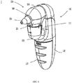
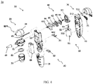
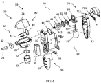
- a nasal aspirator 1 includes a main body 10, a sucking unit 20, a power supply unit 30, an air extracting unit 50 and a lighting unit 60.
- the main body 10 includes a first shell member 11, a second shell member 12 and a cover 13.
- the first shell member 11 is a front shell member of the nasal aspirator 1
- the second shell member 12 is a rear shell member of the nasal aspirator 1
- the cover 13 is a battery lid.
- the sucking unit 20 is coupled with and extended out of the main body 10, and configured to insert a nasal cavity of human body to suck snot.
- the sucking unit 20 further includes a sucking part 21, a sealing washer 22, a collecting container 23, a top lid 24 and a suction head 25.
- the sealing washer 22 is combined with the collecting container 23 under the sucking part 21, and the suction head 25 can be inserted into the nasal cavity of human body to suck snot, and the sucked snot is collected in the collecting container 23.
- the lighting unit 60 is disposed in the sucking unit 20. In this embodiment, the lighting unit 60 and the suction head 25 are combined and disposed in the front of the sucking part 21, and covered by the top lid 24, thereby forming the sucking unit 20 integrally.
- the lighting unit 60 includes a light-emitting element 61 which can be a solid state light source or a gaseous light source, such as a light-emitting diode or a bulb, upon design demand.
- the sucking unit 20 includes an optical conductor 62 for conducting light generated from the lighting unit 60.
- the optical conductor 62 can be in an annular shape, a pillar shape, or a tapered shape. In this embodiment, an annular-shaped optical conductor is taken as an example for illustration.
- the light emitted by the light-emitting element 61 is conducted to the outside through the optical conductor 62.
- the suction head 25 can be an optical conductor or includes light guide material without extra using the optical conductor.
- the power supply unit 30 is disposed in a space formed between the first shell member 11 of the main body 10 and the cover 13, and configured to drive the air extracting unit 50 and the lighting unit 60.
- the power supply unit 30 is electrically coupled with the air extracting unit 50 and the lighting unit 60 through electrodes for providing power.
- the power supply unit 30 includes a first electrode set 31, a second electrode set 32 and a battery set 33.
- the first electrode set 31 and the second electrode set 32 are mounted on the first shell member 11, and the battery set 33 provides power through the first electrode set 31 and the second electrode set 32.
- the air extracting unit 50 is disposed in the main body 10, and includes an air pump 40 configured to enable the sucking unit 20 to have a negative pressure function.
- the air pump 40 includes a chuck 41, a holder 42, a non-return valve 43, and an air extracting part 44 which includes an air inlet 441 and an air outlet 442.
- the air pump 40 further includes a DC motor 51, an eccentric part 52, an eccentric shaft 53, an air pump connecting member 54 and a chuck connecting member 55.
- the DC motor 51 is electrically coupled with the power supply unit 30, and includes a rotating shaft 511, and all of the rotating shaft 511, the eccentric part 52 and the eccentric shaft 53 form an eccentric mechanism which is inserted through the air pump connecting member 54 to interlink with the chuck connecting member 55, and the chuck connecting member 55 is interlinked with the chuck 41.
- the nasal aspirator 1 of the present disclosure further includes a control unit 70, a power switch 71 and a switch (not shown in figures).
- the power switch 71 includes a plate 711 and a plate frame 712.
- the control unit 70 is disposed in the main body 10 and electrically coupled with the air extracting unit 50 and the lighting unit 60. Through the control unit 70, the power switch 71 and the switch can be used to drive the air extracting unit 50 and the lighting unit 60.
- the user can press the power switch 71, and the power switch 71 then drives the lighting unit 60 and the air extracting unit 50 (for example, the air pump 40 of the air extracting unit 50) at the same time through the control unit 70, so that the lighting unit 60 can emit light to facilitate alignment of the suction head 25 with the nasal cavity for sucking snot.
- the control unit 70 can control the lighting unit 60 to drive the light-emitting element 61, and after the suction head 25 is aligned with and inserted into the nasal cavity, the air pump 40 is driven to suck snot.
- the switch can be used to drive the air extracting unit 50 and the lighting unit 60 at the same time or one after another.
- the power supply unit 30 is in contact with the air extracting unit 50 and the lighting unit 60 through the electrodes for providing power during the process of operating the nasal aspirator 1.
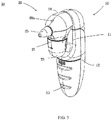
- FIGs. 3 and 4 show modification of the first preferred embodiment of the nasal aspirator 1 of the present disclosure.
- Major elements of the nasal aspirator 1a are the same as that of the nasal aspirator 1, so their detailed descriptions are not repeated.
- the difference between the nasal aspirator 1a and the nasal aspirator 1 is that the light-emitting element 61 of the lighting unit 60a of the nasal aspirator 1a is directly mounted on the top lid 24 of the sucking unit 20, in order to directly illuminate the nasal cavity through an opening of the top lid.
- the nasal aspirator 1a has advantage in simpler structure of the lighting unit 60a for easier production.
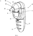
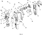
- a nasal aspirator 2 includes a main body 10, a sucking unit 20, a power supply unit 30, an air extracting unit 50 and a lighting unit 60.
- the main body 10 includes a first shell member 11, a second shell member 12 and a cover 13.
- the first shell member 11 is a front shell member of the nasal aspirator 2
- the second shell member 12 is a rear shell member of the nasal aspirator 2
- the cover 13 is a battery lid of the nasal aspirator 2.
- Major elements of the nasal aspirator 2 are the same as that of the nasal aspirator 1, so their detailed descriptions are not repeated.
- the nasal aspirator 2 further includes a sensing module 80 including a first sensing device 81 and a second sensing device 82, as shown in FIG. 6 .
- the first sensing device 81 and the second sensing device 82 are disposed in the main body 10 and the sucking unit 20 separately.
- the first sensing device 81 is electrically coupled with the power supply unit 30.
- the power supply unit 30 provides power to drive the first sensing device 81
- the second sensing device 82 is also triggered at the same time to enable the lighting unit 60 to emit light.
- the first sensing device 81 and the second sensing device 82 are not directly electrically connected with each other, and the first sensing device 81 delivers power to the second sensing device 82 by an electromagnetic induction manner, so that the second sensing device 82 can be triggered to enable the lighting unit 60 to emit light.
- the process of operating the nasal aspirator 2 of the present disclosure will be described in the following.
- the user can press the power switch 71, the power switch 71 then directly drives the lighting unit 60 and the air extracting unit 50 (such as the air pump 40 of the air extracting unit 50) at the same time through the control unit 70, so that the lighting unit 60 emits light to facilitate alignment of the suction head 25 with the nasal cavity for sucking snot.
- the control unit 70 can also control the lighting unit 60 to drive the light-emitting element 61, and after the suction head 25 is aligned with and inserted into the nasal cavity, the air pump 40 is then driven to suck snot.
- the switch can be used to drive the air extracting unit 50 and the lighting unit 60 at the same time or one after another.
- the power switch 71 can enable the power supply unit 30 to trigger the first sensing device 81 and the second sensing device 82 both, thereby driving the control unit 70; or, after the power switch 71 electrically drives the control unit 70, the power switch 71 can enable the first sensing device 81 to trigger the second sensing device 82 for then driving the lighting unit 60 and the air extracting unit 50.
- FIGs. 7 and 8 show modification of the nasal aspirator 2 of the present disclosure.
- Major elements of a nasal aspirator 2a are the same as that of the nasal aspirator both, and difference of the nasal aspirator 2a and the nasal aspirator 2 is that the optical conductor 62 of the lighting unit 60b is a light pipe, and the light-emitting element 61 is mounted in the optical conductor 62.
- the lighting unit 60b of the nasal aspirator 2 can be more efficient in light emission.
Landscapes
- Health & Medical Sciences (AREA)
- Heart & Thoracic Surgery (AREA)
- Vascular Medicine (AREA)
- Engineering & Computer Science (AREA)
- Anesthesiology (AREA)
- Biomedical Technology (AREA)
- Hematology (AREA)
- Life Sciences & Earth Sciences (AREA)
- Animal Behavior & Ethology (AREA)
- General Health & Medical Sciences (AREA)
- Public Health (AREA)
- Veterinary Medicine (AREA)
- External Artificial Organs (AREA)
- Non-Portable Lighting Devices Or Systems Thereof (AREA)
- Arrangement Of Elements, Cooling, Sealing, Or The Like Of Lighting Devices (AREA)
Claims (10)
- Un aspirateur nasal (1, 2, 2a) avec une fonction d'éclairage, comprenant :Un corps principal (10) ;Un bloc d'alimentation (30), placé dans le corps principal (10) ;Un bloc d'aspiration (20), couplé au corps principal (10) et dépassant de celui-ci ;Un bloc d'extraction d'air (50), placé dans le corps principal (10) et électriquement couplé au bloc d'alimentation (30), et configuré pour permettre au bloc d'aspiration (20) de générer l'aspiration ; etUn bloc d'éclairage (60, 60b), placé dans le bloc d'aspiration (20), où le bloc d'alimentation (30) est configuré pour entraîner le bloc d'extraction d'air (30) et le bloc d'éclairage (60, 60b) ;Caractérisé en ce que :
Le bloc d'aspiration (20) comprend une tête d'aspiration (25) configurée pour être insérée dans une cavité nasale et configurée pour conduire la lumière générée par le bloc d'éclairage (60, 60b). - L'aspirateur nasal selon la revendication 1, caractérisé en outre par un bloc de commande (70), un interrupteur d'alimentation (71) et un interrupteur, où le bloc de commande (70) est électriquement couplé au bloc d'extraction d'air (50) et au bloc d'éclairage (60, 60b), et où l'interrupteur d'alimentation (71) et l'interrupteur sont configurés pour entraîner le bloc d'extraction d'air (50) et le bloc d'éclairage (60, 60b) par le biais du bloc de commande (70).
- L'aspirateur nasal selon la revendication 2, caractérisé en ce que le bloc de commande (70) entraîne le bloc d'extraction d'air (50) et le bloc d'éclairage (60, 60b) en même temps ou l'un après l'autre, en fonction de l'actionnement de l'interrupteur.
- L'aspirateur nasal selon la revendication 1, caractérisé en ce que le bloc d'alimentation (30) est en contact avec le bloc d'extraction d'air (50) et le bloc d'éclairage (60, 60b) par le biais d'électrodes, afin d'assurer l'alimentation.
- L'aspirateur nasal selon la revendication 1, caractérisé en outre par un module capteur (80) qui comprend un premier dispositif capteur (81) et un deuxième dispositif capteur (82) placés séparément dans le corps principal (10) et le bloc d'aspiration (20), où le premier dispositif capteur (81) est électriquement couplé au bloc d'alimentation (30) et où, lorsque le bloc d'alimentation (30) assure l'alimentation pour entraîner le premier dispositif capteur (81), le deuxième dispositif capteur (82) se déclenche également pour permettre au bloc d'éclairage (60, 60b) d'émettre de la lumière.
- L'aspirateur nasal selon la revendication 1 ou 5, caractérisé en ce que le bloc d'extraction d'air (50) comprend une pompe à air (40) configurée pour permettre au bloc d'aspiration (20) d'assurer une fonction de pression négative.
- L'aspirateur nasal selon la revendication 1 ou 5, caractérisé en ce que le bloc d'éclairage (60, 60b) comprend un élément émetteur de lumière (61) qui est une source de lumière à semi-conducteurs ou une source de lumière au gaz.
- L'aspirateur nasal selon la revendication 7, caractérisé en ce que l'élément émetteur de lumière (61) est une diode électroluminescente ou une ampoule.
- L'aspirateur nasal selon la revendication 1 ou 5, caractérisé en ce que la tête d'aspiration (25) est un conducteur optique permettant de conduire la lumière générée par le bloc d'éclairage (60, 60b).
- L'aspirateur nasal selon la revendication 1 ou 5, caractérisé en ce que la tête d'aspiration (25) comprend un matériau de guidage de la lumière pour conduire la lumière générée par le bloc d'éclairage (60, 60b).
Applications Claiming Priority (1)
| Application Number | Priority Date | Filing Date | Title |
|---|---|---|---|
| TW104221090U TWM521464U (zh) | 2015-12-30 | 2015-12-30 | 具照明功能之吸鼻器 |
Publications (2)
| Publication Number | Publication Date |
|---|---|
| EP3187207A1 EP3187207A1 (fr) | 2017-07-05 |
| EP3187207B1 true EP3187207B1 (fr) | 2020-02-05 |
Family
ID=56510068
Family Applications (1)
| Application Number | Title | Priority Date | Filing Date |
|---|---|---|---|
| EP16207031.2A Active EP3187207B1 (fr) | 2015-12-30 | 2016-12-28 | Aspirateur nasal avec fonction d'éclairage |
Country Status (5)
| Country | Link |
|---|---|
| US (1) | US11103631B2 (fr) |
| EP (1) | EP3187207B1 (fr) |
| JP (1) | JP6373338B2 (fr) |
| CN (1) | CN106963993B (fr) |
| TW (1) | TWM521464U (fr) |
Families Citing this family (3)
| Publication number | Priority date | Publication date | Assignee | Title |
|---|---|---|---|---|
| USD849229S1 (en) * | 2017-12-26 | 2019-05-21 | Han Jiang | Nasal aspirator |
| USD883470S1 (en) * | 2019-10-23 | 2020-05-05 | Junjie Wei | Nasal aspirator |
| USD1009249S1 (en) * | 2021-07-13 | 2023-12-26 | Shenzhen Alex Technology Co., Ltd | Ear washer |
Family Cites Families (13)
| Publication number | Priority date | Publication date | Assignee | Title |
|---|---|---|---|---|
| KR20000032005A (ko) * | 1998-11-12 | 2000-06-05 | 김경훈 | 가정용 치료 흡인기 |
| KR200188585Y1 (ko) * | 2000-02-08 | 2000-07-15 | 주식회사지인텍 | 휴대용 콧물 흡입기 |
| TW437394U (en) | 2000-04-10 | 2001-05-28 | Chen Jian Li | Electric suction device for nasal discharge |
| CN2502701Y (zh) * | 2001-09-28 | 2002-07-31 | 陈建利 | 吸鼻器 |
| US20030109854A1 (en) * | 2001-12-11 | 2003-06-12 | Chien-Li Chen | Nasal cleaner |
| CN2860491Y (zh) * | 2005-12-07 | 2007-01-24 | 豪展医疗科技股份有限公司 | 具有音乐之吸鼻器结构 |
| US20080125838A1 (en) * | 2006-08-10 | 2008-05-29 | Medtronic, Inc. | Implantable Devices With Photocatalytic Surfaces |
| TW200848010A (en) * | 2007-06-15 | 2008-12-16 | Avita Corp | Nose vacuum device |
| US20090076441A1 (en) * | 2007-08-15 | 2009-03-19 | Eric Sebban | Aspirator assembly |
| CN101440914A (zh) * | 2007-08-28 | 2009-05-27 | 上海中策工贸有限公司 | 照明系统 |
| WO2010077980A1 (fr) * | 2008-12-16 | 2010-07-08 | Aardvark Medical, Inc. | Procédés et systèmes d'administration de fluides, d'aérosols et d'énergie acoustique à des surfaces de tissu, des cavités et des passages obstrués tels que des ostiums intra-nasaux |
| CN202190110U (zh) * | 2011-05-13 | 2012-04-11 | 天瑞企业股份有限公司 | 非接触式照明充电装置 |
| JP2013070520A (ja) * | 2011-09-22 | 2013-04-18 | Panasonic Corp | 非接触給電装置の駆動方法、非接触給電装置及び非接触給電システム |
-
2015
- 2015-12-30 TW TW104221090U patent/TWM521464U/zh not_active IP Right Cessation
-
2016
- 2016-12-27 JP JP2016252188A patent/JP6373338B2/ja active Active
- 2016-12-27 CN CN201611226777.5A patent/CN106963993B/zh active Active
- 2016-12-28 EP EP16207031.2A patent/EP3187207B1/fr active Active
- 2016-12-30 US US15/394,830 patent/US11103631B2/en active Active
Non-Patent Citations (1)
| Title |
|---|
| None * |
Also Published As
| Publication number | Publication date |
|---|---|
| TWM521464U (zh) | 2016-05-11 |
| CN106963993B (zh) | 2021-03-02 |
| JP2017119106A (ja) | 2017-07-06 |
| US11103631B2 (en) | 2021-08-31 |
| EP3187207A1 (fr) | 2017-07-05 |
| CN106963993A (zh) | 2017-07-21 |
| US20170189590A1 (en) | 2017-07-06 |
| JP6373338B2 (ja) | 2018-08-15 |
Similar Documents
| Publication | Publication Date | Title |
|---|---|---|
| CN106163480B (zh) | 用于患者运输装置的座椅组件 | |
| EP3187207B1 (fr) | Aspirateur nasal avec fonction d'éclairage | |
| JP5608724B2 (ja) | 医療・介護用吸引装置 | |
| CN221866770U (zh) | 一种具有防堵塞和清洗功能的电动吸鼻器 | |
| KR101650845B1 (ko) | 다목적 의료용 광조사 장치 | |
| CN101048184A (zh) | 鼻分泌物吸出装置 | |
| CN221672884U (zh) | 吸奶装置及保护罩 | |
| US20140022768A1 (en) | Child night light/ cup holder | |
| CN212015452U (zh) | 杀螨装置和具有其的清洁设备 | |
| JP2014018499A (ja) | 鼻汁吸引器 | |
| CN214232143U (zh) | 一种倒插式话筒uvc紫外线消毒器 | |
| CN217793917U (zh) | 一种带uv灯杀菌功能的鼻涕收集装置 | |
| CN211460002U (zh) | 除螨仪 | |
| CN218635108U (zh) | 饵盘灯 | |
| CN221712979U (zh) | 一种吸痰器 | |
| CN106212416A (zh) | 笔式小微型昆虫采集器 | |
| CN211155690U (zh) | 一种方便悬挂的口腔仪器用压舌装置 | |
| CN209529765U (zh) | 一种便携式吸痰器 | |
| CN206101395U (zh) | 笔式小微型昆虫采集器 | |
| CN209280666U (zh) | 健康监测装置 | |
| CN217286636U (zh) | 一种吸痰器 | |
| CN210170019U (zh) | 一种吸痰压舌板 | |
| CN221535053U (zh) | 一种吸痰器的吸头 | |
| CN216652260U (zh) | 一种儿童眼科用卡通瞳孔笔 | |
| CN214158046U (zh) | 一种指环消毒笔 |
Legal Events
| Date | Code | Title | Description |
|---|---|---|---|
| PUAI | Public reference made under article 153(3) epc to a published international application that has entered the european phase |
Free format text: ORIGINAL CODE: 0009012 |
|
| STAA | Information on the status of an ep patent application or granted ep patent |
Free format text: STATUS: THE APPLICATION HAS BEEN PUBLISHED |
|
| AK | Designated contracting states |
Kind code of ref document: A1 Designated state(s): AL AT BE BG CH CY CZ DE DK EE ES FI FR GB GR HR HU IE IS IT LI LT LU LV MC MK MT NL NO PL PT RO RS SE SI SK SM TR |
|
| AX | Request for extension of the european patent |
Extension state: BA ME |
|
| STAA | Information on the status of an ep patent application or granted ep patent |
Free format text: STATUS: REQUEST FOR EXAMINATION WAS MADE |
|
| 17P | Request for examination filed |
Effective date: 20180103 |
|
| RBV | Designated contracting states (corrected) |
Designated state(s): AL AT BE BG CH CY CZ DE DK EE ES FI FR GB GR HR HU IE IS IT LI LT LU LV MC MK MT NL NO PL PT RO RS SE SI SK SM TR |
|
| GRAP | Despatch of communication of intention to grant a patent |
Free format text: ORIGINAL CODE: EPIDOSNIGR1 |
|
| STAA | Information on the status of an ep patent application or granted ep patent |
Free format text: STATUS: GRANT OF PATENT IS INTENDED |
|
| INTG | Intention to grant announced |
Effective date: 20190627 |
|
| GRAS | Grant fee paid |
Free format text: ORIGINAL CODE: EPIDOSNIGR3 |
|
| GRAA | (expected) grant |
Free format text: ORIGINAL CODE: 0009210 |
|
| STAA | Information on the status of an ep patent application or granted ep patent |
Free format text: STATUS: THE PATENT HAS BEEN GRANTED |
|
| AK | Designated contracting states |
Kind code of ref document: B1 Designated state(s): AL AT BE BG CH CY CZ DE DK EE ES FI FR GB GR HR HU IE IS IT LI LT LU LV MC MK MT NL NO PL PT RO RS SE SI SK SM TR |
|
| REG | Reference to a national code |
Ref country code: GB Ref legal event code: FG4D |
|
| REG | Reference to a national code |
Ref country code: AT Ref legal event code: REF Ref document number: 1229465 Country of ref document: AT Kind code of ref document: T Effective date: 20200215 |
|
| REG | Reference to a national code |
Ref country code: DE Ref legal event code: R096 Ref document number: 602016029080 Country of ref document: DE |
|
| REG | Reference to a national code |
Ref country code: IE Ref legal event code: FG4D |
|
| REG | Reference to a national code |
Ref country code: CH Ref legal event code: EP |
|
| REG | Reference to a national code |
Ref country code: NL Ref legal event code: MP Effective date: 20200205 |
|
| PG25 | Lapsed in a contracting state [announced via postgrant information from national office to epo] |
Ref country code: RS Free format text: LAPSE BECAUSE OF FAILURE TO SUBMIT A TRANSLATION OF THE DESCRIPTION OR TO PAY THE FEE WITHIN THE PRESCRIBED TIME-LIMIT Effective date: 20200205 Ref country code: FI Free format text: LAPSE BECAUSE OF FAILURE TO SUBMIT A TRANSLATION OF THE DESCRIPTION OR TO PAY THE FEE WITHIN THE PRESCRIBED TIME-LIMIT Effective date: 20200205 Ref country code: NO Free format text: LAPSE BECAUSE OF FAILURE TO SUBMIT A TRANSLATION OF THE DESCRIPTION OR TO PAY THE FEE WITHIN THE PRESCRIBED TIME-LIMIT Effective date: 20200505 Ref country code: PT Free format text: LAPSE BECAUSE OF FAILURE TO SUBMIT A TRANSLATION OF THE DESCRIPTION OR TO PAY THE FEE WITHIN THE PRESCRIBED TIME-LIMIT Effective date: 20200628 |
|
| REG | Reference to a national code |
Ref country code: LT Ref legal event code: MG4D |
|
| PG25 | Lapsed in a contracting state [announced via postgrant information from national office to epo] |
Ref country code: BG Free format text: LAPSE BECAUSE OF FAILURE TO SUBMIT A TRANSLATION OF THE DESCRIPTION OR TO PAY THE FEE WITHIN THE PRESCRIBED TIME-LIMIT Effective date: 20200505 Ref country code: SE Free format text: LAPSE BECAUSE OF FAILURE TO SUBMIT A TRANSLATION OF THE DESCRIPTION OR TO PAY THE FEE WITHIN THE PRESCRIBED TIME-LIMIT Effective date: 20200205 Ref country code: HR Free format text: LAPSE BECAUSE OF FAILURE TO SUBMIT A TRANSLATION OF THE DESCRIPTION OR TO PAY THE FEE WITHIN THE PRESCRIBED TIME-LIMIT Effective date: 20200205 Ref country code: LV Free format text: LAPSE BECAUSE OF FAILURE TO SUBMIT A TRANSLATION OF THE DESCRIPTION OR TO PAY THE FEE WITHIN THE PRESCRIBED TIME-LIMIT Effective date: 20200205 Ref country code: GR Free format text: LAPSE BECAUSE OF FAILURE TO SUBMIT A TRANSLATION OF THE DESCRIPTION OR TO PAY THE FEE WITHIN THE PRESCRIBED TIME-LIMIT Effective date: 20200506 Ref country code: IS Free format text: LAPSE BECAUSE OF FAILURE TO SUBMIT A TRANSLATION OF THE DESCRIPTION OR TO PAY THE FEE WITHIN THE PRESCRIBED TIME-LIMIT Effective date: 20200605 |
|
| PG25 | Lapsed in a contracting state [announced via postgrant information from national office to epo] |
Ref country code: NL Free format text: LAPSE BECAUSE OF FAILURE TO SUBMIT A TRANSLATION OF THE DESCRIPTION OR TO PAY THE FEE WITHIN THE PRESCRIBED TIME-LIMIT Effective date: 20200205 |
|
| PG25 | Lapsed in a contracting state [announced via postgrant information from national office to epo] |
Ref country code: SK Free format text: LAPSE BECAUSE OF FAILURE TO SUBMIT A TRANSLATION OF THE DESCRIPTION OR TO PAY THE FEE WITHIN THE PRESCRIBED TIME-LIMIT Effective date: 20200205 Ref country code: CZ Free format text: LAPSE BECAUSE OF FAILURE TO SUBMIT A TRANSLATION OF THE DESCRIPTION OR TO PAY THE FEE WITHIN THE PRESCRIBED TIME-LIMIT Effective date: 20200205 Ref country code: LT Free format text: LAPSE BECAUSE OF FAILURE TO SUBMIT A TRANSLATION OF THE DESCRIPTION OR TO PAY THE FEE WITHIN THE PRESCRIBED TIME-LIMIT Effective date: 20200205 Ref country code: RO Free format text: LAPSE BECAUSE OF FAILURE TO SUBMIT A TRANSLATION OF THE DESCRIPTION OR TO PAY THE FEE WITHIN THE PRESCRIBED TIME-LIMIT Effective date: 20200205 Ref country code: ES Free format text: LAPSE BECAUSE OF FAILURE TO SUBMIT A TRANSLATION OF THE DESCRIPTION OR TO PAY THE FEE WITHIN THE PRESCRIBED TIME-LIMIT Effective date: 20200205 Ref country code: SM Free format text: LAPSE BECAUSE OF FAILURE TO SUBMIT A TRANSLATION OF THE DESCRIPTION OR TO PAY THE FEE WITHIN THE PRESCRIBED TIME-LIMIT Effective date: 20200205 Ref country code: EE Free format text: LAPSE BECAUSE OF FAILURE TO SUBMIT A TRANSLATION OF THE DESCRIPTION OR TO PAY THE FEE WITHIN THE PRESCRIBED TIME-LIMIT Effective date: 20200205 Ref country code: DK Free format text: LAPSE BECAUSE OF FAILURE TO SUBMIT A TRANSLATION OF THE DESCRIPTION OR TO PAY THE FEE WITHIN THE PRESCRIBED TIME-LIMIT Effective date: 20200205 |
|
| REG | Reference to a national code |
Ref country code: DE Ref legal event code: R097 Ref document number: 602016029080 Country of ref document: DE |
|
| REG | Reference to a national code |
Ref country code: AT Ref legal event code: MK05 Ref document number: 1229465 Country of ref document: AT Kind code of ref document: T Effective date: 20200205 |
|
| PLBE | No opposition filed within time limit |
Free format text: ORIGINAL CODE: 0009261 |
|
| STAA | Information on the status of an ep patent application or granted ep patent |
Free format text: STATUS: NO OPPOSITION FILED WITHIN TIME LIMIT |
|
| 26N | No opposition filed |
Effective date: 20201106 |
|
| PG25 | Lapsed in a contracting state [announced via postgrant information from national office to epo] |
Ref country code: AT Free format text: LAPSE BECAUSE OF FAILURE TO SUBMIT A TRANSLATION OF THE DESCRIPTION OR TO PAY THE FEE WITHIN THE PRESCRIBED TIME-LIMIT Effective date: 20200205 |
|
| PG25 | Lapsed in a contracting state [announced via postgrant information from national office to epo] |
Ref country code: PL Free format text: LAPSE BECAUSE OF FAILURE TO SUBMIT A TRANSLATION OF THE DESCRIPTION OR TO PAY THE FEE WITHIN THE PRESCRIBED TIME-LIMIT Effective date: 20200205 Ref country code: SI Free format text: LAPSE BECAUSE OF FAILURE TO SUBMIT A TRANSLATION OF THE DESCRIPTION OR TO PAY THE FEE WITHIN THE PRESCRIBED TIME-LIMIT Effective date: 20200205 |
|
| REG | Reference to a national code |
Ref country code: CH Ref legal event code: PL |
|
| GBPC | Gb: european patent ceased through non-payment of renewal fee |
Effective date: 20201228 |
|
| PG25 | Lapsed in a contracting state [announced via postgrant information from national office to epo] |
Ref country code: MC Free format text: LAPSE BECAUSE OF FAILURE TO SUBMIT A TRANSLATION OF THE DESCRIPTION OR TO PAY THE FEE WITHIN THE PRESCRIBED TIME-LIMIT Effective date: 20200205 |
|
| REG | Reference to a national code |
Ref country code: BE Ref legal event code: MM Effective date: 20201231 |
|
| PG25 | Lapsed in a contracting state [announced via postgrant information from national office to epo] |
Ref country code: IE Free format text: LAPSE BECAUSE OF NON-PAYMENT OF DUE FEES Effective date: 20201228 Ref country code: LU Free format text: LAPSE BECAUSE OF NON-PAYMENT OF DUE FEES Effective date: 20201228 |
|
| PG25 | Lapsed in a contracting state [announced via postgrant information from national office to epo] |
Ref country code: GB Free format text: LAPSE BECAUSE OF NON-PAYMENT OF DUE FEES Effective date: 20201228 Ref country code: LI Free format text: LAPSE BECAUSE OF NON-PAYMENT OF DUE FEES Effective date: 20201231 Ref country code: CH Free format text: LAPSE BECAUSE OF NON-PAYMENT OF DUE FEES Effective date: 20201231 |
|
| PG25 | Lapsed in a contracting state [announced via postgrant information from national office to epo] |
Ref country code: TR Free format text: LAPSE BECAUSE OF FAILURE TO SUBMIT A TRANSLATION OF THE DESCRIPTION OR TO PAY THE FEE WITHIN THE PRESCRIBED TIME-LIMIT Effective date: 20200205 Ref country code: MT Free format text: LAPSE BECAUSE OF FAILURE TO SUBMIT A TRANSLATION OF THE DESCRIPTION OR TO PAY THE FEE WITHIN THE PRESCRIBED TIME-LIMIT Effective date: 20200205 Ref country code: CY Free format text: LAPSE BECAUSE OF FAILURE TO SUBMIT A TRANSLATION OF THE DESCRIPTION OR TO PAY THE FEE WITHIN THE PRESCRIBED TIME-LIMIT Effective date: 20200205 |
|
| PG25 | Lapsed in a contracting state [announced via postgrant information from national office to epo] |
Ref country code: MK Free format text: LAPSE BECAUSE OF FAILURE TO SUBMIT A TRANSLATION OF THE DESCRIPTION OR TO PAY THE FEE WITHIN THE PRESCRIBED TIME-LIMIT Effective date: 20200205 Ref country code: AL Free format text: LAPSE BECAUSE OF FAILURE TO SUBMIT A TRANSLATION OF THE DESCRIPTION OR TO PAY THE FEE WITHIN THE PRESCRIBED TIME-LIMIT Effective date: 20200205 |
|
| PG25 | Lapsed in a contracting state [announced via postgrant information from national office to epo] |
Ref country code: BE Free format text: LAPSE BECAUSE OF NON-PAYMENT OF DUE FEES Effective date: 20201231 |
|
| PGFP | Annual fee paid to national office [announced via postgrant information from national office to epo] |
Ref country code: DE Payment date: 20251127 Year of fee payment: 10 |
|
| PGFP | Annual fee paid to national office [announced via postgrant information from national office to epo] |
Ref country code: IT Payment date: 20251218 Year of fee payment: 10 |
|
| PGFP | Annual fee paid to national office [announced via postgrant information from national office to epo] |
Ref country code: FR Payment date: 20251120 Year of fee payment: 10 |