EP3187671B1 - Dispositif de verrouillage en tant que sécurité anti-effraction pour par exemple des fenêtres et des portes - Google Patents
Dispositif de verrouillage en tant que sécurité anti-effraction pour par exemple des fenêtres et des portes Download PDFInfo
- Publication number
- EP3187671B1 EP3187671B1 EP16205003.3A EP16205003A EP3187671B1 EP 3187671 B1 EP3187671 B1 EP 3187671B1 EP 16205003 A EP16205003 A EP 16205003A EP 3187671 B1 EP3187671 B1 EP 3187671B1
- Authority
- EP
- European Patent Office
- Prior art keywords
- bolt
- pivot lever
- locking
- locking device
- longitudinal axis
- Prior art date
- Legal status (The legal status is an assumption and is not a legal conclusion. Google has not performed a legal analysis and makes no representation as to the accuracy of the status listed.)
- Not-in-force
Links
- 230000000903 blocking effect Effects 0.000 claims description 17
- 239000000463 material Substances 0.000 claims description 6
- 230000006835 compression Effects 0.000 claims description 5
- 238000007906 compression Methods 0.000 claims description 5
- 238000009420 retrofitting Methods 0.000 claims description 2
- 230000000295 complement effect Effects 0.000 claims 4
- NJPPVKZQTLUDBO-UHFFFAOYSA-N novaluron Chemical compound C1=C(Cl)C(OC(F)(F)C(OC(F)(F)F)F)=CC=C1NC(=O)NC(=O)C1=C(F)C=CC=C1F NJPPVKZQTLUDBO-UHFFFAOYSA-N 0.000 description 6
- 238000011161 development Methods 0.000 description 3
- 230000018109 developmental process Effects 0.000 description 3
- 238000005553 drilling Methods 0.000 description 3
- 229910052782 aluminium Inorganic materials 0.000 description 2
- XAGFODPZIPBFFR-UHFFFAOYSA-N aluminium Chemical compound [Al] XAGFODPZIPBFFR-UHFFFAOYSA-N 0.000 description 2
- 238000006073 displacement reaction Methods 0.000 description 2
- 239000004033 plastic Substances 0.000 description 2
- 229920003023 plastic Polymers 0.000 description 2
- 208000010543 22q11.2 deletion syndrome Diseases 0.000 description 1
- 229910000838 Al alloy Inorganic materials 0.000 description 1
- CWYNVVGOOAEACU-UHFFFAOYSA-N Fe2+ Chemical compound [Fe+2] CWYNVVGOOAEACU-UHFFFAOYSA-N 0.000 description 1
- 229920002430 Fibre-reinforced plastic Polymers 0.000 description 1
- 229910000831 Steel Inorganic materials 0.000 description 1
- 239000000853 adhesive Substances 0.000 description 1
- 230000001070 adhesive effect Effects 0.000 description 1
- 239000002390 adhesive tape Substances 0.000 description 1
- 230000001419 dependent effect Effects 0.000 description 1
- 230000000694 effects Effects 0.000 description 1
- 210000003746 feather Anatomy 0.000 description 1
- 239000011151 fibre-reinforced plastic Substances 0.000 description 1
- 239000007788 liquid Substances 0.000 description 1
- 229910052751 metal Inorganic materials 0.000 description 1
- 239000002184 metal Substances 0.000 description 1
- 229910001092 metal group alloy Inorganic materials 0.000 description 1
- 150000002739 metals Chemical class 0.000 description 1
- 238000000034 method Methods 0.000 description 1
- 235000011837 pasties Nutrition 0.000 description 1
- 239000010959 steel Substances 0.000 description 1
- 230000007704 transition Effects 0.000 description 1
Images


Classifications
-
- E—FIXED CONSTRUCTIONS
- E05—LOCKS; KEYS; WINDOW OR DOOR FITTINGS; SAFES
- E05B—LOCKS; ACCESSORIES THEREFOR; HANDCUFFS
- E05B63/00—Locks or fastenings with special structural characteristics
- E05B63/0004—Additional locks added to existing lock arrangements
-
- E—FIXED CONSTRUCTIONS
- E05—LOCKS; KEYS; WINDOW OR DOOR FITTINGS; SAFES
- E05B—LOCKS; ACCESSORIES THEREFOR; HANDCUFFS
- E05B17/00—Accessories in connection with locks
- E05B17/20—Means independent of the locking mechanism for preventing unauthorised opening, e.g. for securing the bolt in the fastening position
- E05B17/2007—Securing, deadlocking or "dogging" the bolt in the fastening position
- E05B17/208—Securing, deadlocking or "dogging" the bolt in the fastening position by means of an additional dogging movement of a rotary bolt
-
- E—FIXED CONSTRUCTIONS
- E05—LOCKS; KEYS; WINDOW OR DOOR FITTINGS; SAFES
- E05B—LOCKS; ACCESSORIES THEREFOR; HANDCUFFS
- E05B63/00—Locks or fastenings with special structural characteristics
- E05B63/0052—Locks mounted on the "frame" cooperating with means on the "wing"
-
- E—FIXED CONSTRUCTIONS
- E05—LOCKS; KEYS; WINDOW OR DOOR FITTINGS; SAFES
- E05C—BOLTS OR FASTENING DEVICES FOR WINGS, SPECIALLY FOR DOORS OR WINDOWS
- E05C3/00—Fastening devices with bolts moving pivotally or rotatively
- E05C3/004—Fastening devices with bolts moving pivotally or rotatively about an axis perpendicular to the surface on which the fastener is mounted
-
- E—FIXED CONSTRUCTIONS
- E05—LOCKS; KEYS; WINDOW OR DOOR FITTINGS; SAFES
- E05C—BOLTS OR FASTENING DEVICES FOR WINGS, SPECIALLY FOR DOORS OR WINDOWS
- E05C3/00—Fastening devices with bolts moving pivotally or rotatively
- E05C3/02—Fastening devices with bolts moving pivotally or rotatively without latching action
Definitions
- the invention relates to a burglar alarm locking device, in particular for subsequent attachment to a window or door. Accordingly, the invention also relates to a window or a door which has at least one such locking device or a plurality of such locking devices or to which at least one or more such locking devices are subsequently attached.
- the DE 20 2010 004 837 U1 shows in FIG. 5 a window comprising a window frame and a sash pivotally mounted to the window frame, wherein three locking devices are attached to the frame and serve to prevent opening of the window.
- Each of the locking devices has a latch which does not protrude into the opening pivot region of the window sash relative to a holder in a first rotational position and projects into the opening pivot region of the window sash in a second rotational position.
- the bolt can be locked in each case in the first rotational position and the second rotational position of the pivot lever. When the latch projects into the opening pivot area of the sash, the sash is blocked against swinging.
- the DE 20 2010 004 837 U1 discloses a locking device according to the preamble of claim 1.
- the locking device from the German utility model 20 2010 004 837 has at a square of a bolt, which is integrally formed with the bolt, a 90 ° countersink, in which a threaded pin with a 90 ° tip, which engages in the 90 ° countersink of the bolt and thereby prevents the bolt from an engaged position to the disengaged position.
- the grub screw has a special inner profile similar to a rim lock to solve the grub screw with a special tool can. In fact, the special tool makes it difficult to loosen the threaded pin. In view of the fact that burglars usually penetrate from the outside by levering the window or door into a building, the inner profile for the special tool only becomes important if the burglar is already in the building.
- the additional requirement of a special tool does not appear to significantly increase the utility of the device, but to drive up costs.
- the requirement of a special tool for opening the locking device to open the window may even be dangerous, namely when fire breaks out in the building and people want to escape to the outside through the window. If the special tool is not available or the fear of the escaping persons in front of the fire does not allow an adequate use of the special tool, this escape route is blocked by the window.
- the US 7,537,250 B1 shows a child safety device for drawers and doors, which has a main body and a pivotally mounted thereon locking element, which can engage in one of two rotational positions in a recess of the body.
- the DE 20 2015 104 749 U1 discloses a securing device for a window or a door, with a fastened to the door or window frame body and a rotatably mounted on the body blocking body.
- the base of the locking device has a bore.
- a bore is not necessarily understood to mean only a breakthrough made by the drilling process, but also cylindrical breakthroughs that can be otherwise made.
- the bore serves to support and guide a bolt, in particular a cylindrical bolt of a pivot lever.
- the base is attached to a frame, in particular window or door frame, as for example glued, for example with a suitable preferably liquid or pasty adhesive or a preferably double-sided adhesive tape, and / or screwed, as for example by means of at least one screw with its socket is firmly anchored in the frame, wherein the socket is then bordered, in particular clamped, between the frame and the screw head of the at least one screw, and / or by means of a rivet connection comprising at least one rivet, and / or a plug or latching connection, or other suitable connection.
- the base can have, in particular on its underside, an intended for attachment to the frame or the wing and in particular formed contact surface.
- the contact surface may abut the frame when the socket or locking device is attached to the frame or against the wing when the socket or locking device is attached to the wing.
- the bore and / or the bolt or its center axes are arranged parallel to and spaced from the contact surface.
- the pedestal such as at least one attachment portion of the pedestal, may have at least one bore for the at least one screw or at least one rivet through which the shaft of the at least one screw or at least one rivet extends.
- two screws or rivets and two holes for the screws or rivets may be provided for fastening the base.
- the pedestal or locking device is attached to the side of the frame, which faces inside the building.
- the window or door opens often or usually also to the inside of the building. If the door or window sash pivot on opening to the building exterior, the sill may or may not be attached to the door or window sash and the frame will block the pivot lever and thus pivot the window or door, thereby preventing the window or door from being pried open can be.
- the locking device has a pivot lever which has a locking bolt and a bolt projecting from the locking latch, extending into the bore and having a longitudinal axis.
- the locking bar may, for example, be cuboid or have another suitable shape.
- the particular cylindrical bolt extends into the bore, in particular completely through the bore, as a through hole can be configured, through and is rotatably guided by the bore and axially displaceable.
- the bolt is rotatably and axially fixed to the lock bolt as a separate part, in particular glued and / or either pressed or screwed.
- a bolt joined to the locking bar has the advantage that the pivoting lever is cheaper to produce and that the bolt can be made, for example, of a material other than the locking bar, whereby a material can be used for the bolt, which has a higher strength than the locking bolt having.
- the bolt and the locking member are formed of different materials, such as metals or metal alloys or plastics.
- the locking bolt of an aluminum material, ie aluminum or an aluminum alloy, or of a plastic, such as.
- fiber reinforced plastic and the bolt of a ferrous material, such as steel, be made.
- the pivot lever may have a first rotational position about the longitudinal axis and a second rotational position about the longitudinal axis with respect to the pedestal.
- the elongated locking bolt whose longitudinal direction or axis is transversely or perpendicular to the longitudinal axis of the bolt, be pivoted in the second rotational position relative to the first rotational position substantially at 90 ° about the longitudinal axis.
- the pivot lever In the first rotational position and the second rotational position, the pivot lever is displaceable between an engaged position and a disengaged position relative to the base, in particular along the longitudinal axis of the bolt.
- the bore can serve as a longitudinal guide for the bolt.
- the pivot lever is in its engaged position, which it can assume in the first and second rotational position, blocked by the base against rotation about the longitudinal axis of the bolt, in particular in both directions of rotation.
- the pivot lever is rotatable in its disengaged position about the longitudinal axis of the bolt between the first rotational position and the second rotational position, in particular, the pedestal can not prevent rotation of the pivot lever in its disengaged position.
- the invention is characterized by a spring which is adapted to act between the base and the pivot lever so that the pivot lever is held by the spring in its engaged position, in particular when the pivot lever is in its first or second rotational position.
- the spring pushes the pivot lever in the engaged position.
- the pivot lever can be easily solved by being displaced against the spring or compression of the spring from the engaged position to the disengaged position.
- the locking device can be solved in a simple manner and without special tool by a located on the inside of the window or door position, especially if the person wants to open the window or door. From the outside, however, a secure burglary protection is still given.
- the spring acts as a compression spring and is designed as a helical or spiral spring. When moving the pivot lever from the engaged position to the disengaged position, the compression spring is tensioned to pressure.
- the spring is supported at its first end to the base and at its second end to the bolt or on a part axially fixed to the bolt part.
- the at least axially fixed part such as a backup or grooved ring or a screw, be attached to which the second end of the spring is supported.
- the axialfest joined part is in the region of the free end of the bolt, d. H. of the locking bar projecting end of the bolt, attached.
- a screw may, for example, be screwed with its shaft end face into the end of the bolt, wherein the spring can be supported on the screw head of the screw.
- the spring may surround a portion of the bolt.
- the base may have a portion, such as a bearing portion, through which the bore (Through hole) extends continuously, wherein on one side of the portion of the base of the locking bar and on the other side of the portion of the base a portion of the bolt protrudes, said portion of the bolt is surrounded by the spring or disposed within the spring.
- the spring may be arranged or configured to be tensioned when the pivot lever is moved from its engaged position to its disengaged position. Accordingly, the spring is relaxed when the pivot lever is moved from its disengaged position to its engaged position.
- the base can have an axial stop surface, in particular the portion of the base which has the bore or through which the bore extends, wherein the axial stop surface at least partially surrounds the bore and / or substantially perpendicular to the Bohrungsffenachse, which substantially Longitudinal axis of the bolt corresponds, stands.
- the locking latch may have an axial abutment counter surface which abuts the axial abutment surface in the engaged position of the pivot lever and is moved away from the axial abutment surface as the pivot lever is moved to its disengaged position.
- the substantially perpendicular, ie normal, bolt on the axial abutment counter-surface extends from the axial abutment counter-surface cylindrically towards its free end.
- the shows DE 20 2010 004 837 U1 a bolt having a portion with a circular cross section and a portion with a square cross section.
- the bolt according to the invention does not have the square cross section, so that the bolt according to the invention is easier to produce.
- the pedestal may include a rotation stop surface, wherein the rotation stop surface is arranged to block the rotation of the pivot lever about the longitudinal axis by abutting a first rotation stop counter surface of the locking bar on the rotation stop surface, when the pivot lever is in its first rotational position, and a second Rotary stop against stop surface of the locking bolt abuts the Drehanschlag phenomenon when the pivot lever is in its second rotational position.
- the rotational stop surface of the base can be substantially perpendicular to the axial stop surface.
- the first rotary abutment counter surface may be substantially perpendicular to the second rotary abutment counter surface.
- the first rotation abutment counter surface and / or the second rotation abutment counter surface can each be formed by an edge of the locking bolt.
- the locking device may, for example, comprise a blocking element.
- a first variant of a blocking element can be arranged on the portion of the base which has the bore or through which the bore extends.
- the blocking element can engage between a blocking position in which the blocking element engages in the bolt, in particular in a recess formed on the bolt, such as, for example, an annular groove, so that the bolt and thus the pivot lever are locked against displacement from the engaged position into the disengaged position is or can be locked, and a release position to be moved back and forth, wherein in the release position, the engagement of the locking element is dissolved in the bolt, whereby the bolt and thus the pivot lever along the longitudinal axis are displaceable.
- the blocking element can be a screw, such as one from the DE 20 2010 004 837 U1 designed threaded pin, be.
- the locking element may be a spring-mounted pin which is resiliently for disengaging relative to the base resiliently withdrawn from engagement with the bolt and when released by the resilient mounting back into the bore in which the bolt is mounted, in particular the recess of Bolzens is movable into it.
- a second variant of the locking element comprises a sleeve-shaped blocking element, which has a particular continuous slot along its longitudinal axis, whereby the locking element with a movement transverse to the longitudinal axis on the bolt and in particular on the spring applied to the pin can be plugged.
- the blocking element can be pushed over the protruding from the bore portion of the bolt, on the opposite side of the locking bolt of the bore portion having the Socket is arranged.
- the blocking element can be in the plugged state, on the one hand to the base and on the other hand to the bolt or an axially fixed to the bolt part, such as the above-mentioned backup or Nutenring or the above screw support, when the locking element is plugged.
- the blocking element can block the displacement of the pivot lever from the engaged position to the disengaged position, since the sleeve-shaped blocking element is preferably not compressible in its longitudinal direction. Also, this embodiment of the locking element allows a release of the locking element without special tool by the locking element is easily removed again laterally from the bolt.
- the invention relates to a window or a door, which comprises a frame and a wing pivotally attached to the frame, in particular a door leaf or a window wing, wherein at least one locking device of the type claimed herein can be fastened to the frame, wherein the locking latch in the first rotational position of the pivot lever does not protrude in the opening pivot region of the wing, whereby the wing can be swung open, and wherein the locking bar in the second rotational position of the pivot lever projects into the opening pivot region of the wing, whereby the wing is blocked against pivoting.
- the one or more locking devices are preferably located at the locations of the frame where they can most effectively prevent the window or door from being pried open.
- the locking device can be attached to the window or door leaf, wherein the locking bolt is pressed against the frame in an attempt to open the window or door, thus blocking a swiveling.
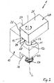
- the locking device 1 a base 10 and a in a disengaged axial position relative to the base 10 about the longitudinal axis L between at least a first rotational position and a second rotational position, such as pivotable about 90 ° pivot lever 20.
- the base 10 has a bearing portion and two fastening portions, which are arranged laterally of the bearing portion on. Alternatively, a single attachment portion or may more than two, such. B. three or four mounting portions may be provided on the base 10. Generally, at least one or at least two attachment portions are provided.
- the bearing portion has a cylindrical bore 11 extending along the longitudinal axis L, which extends completely from one side of the bearing portion to the other side of the bearing portion.
- Each of the mounting portions has one or at least one bore 28, such as two, three or more holes 28, in which a screw, in particular a screw head is or is retractably received, wherein the Screw for fixing the locking device 1 or the base 10 to the frame 3 of a window 2 or a door is used.
- the central axes of the bores 28 are perpendicular to the longitudinal axis L, ie the central axis of a bolt 22 or the bore 11 and may, for example, but need not necessarily intersect the longitudinal axis L or the central axis of the bolt 22 or the bore 11. That is, the center axes of the bores 28 may be spaced from the longitudinal axis L.
- the base 10 can be provided on the base 10, one or more holes for receiving a screw, in particular for the recessed receiving the screw head may be provided, wherein the screw is used to attach the locking device 1 or the base 10 to the frame of a window 1 or a door.
- This at least one bore or its center axis can be arranged perpendicular to and spaced from the longitudinal axis L and / or arranged parallel to the axial stop surface 12 and / or the rotational stop surface 13.
- the fixing portion is sandwiched between the frame 3 or the wing 4 and the head of the screw whose threaded portion of its stem is anchored in the frame 3 or the wing 4 when the base 10 is fixed to the frame 3 or the wing 4 is.
- the holes 28 are perpendicular, ie normal to the contact surface of the base 10 for the frame 3 or the wing 4.
- the contact surface is vorgeh Scientific and designed to abut the frame 3 or a wing 4, when the base 10 is fixed to the frame 3 ,
- the central axis of the bore 11 or the longitudinal axis L extends parallel and spaced from the contact surface.
- the pivot lever 20 has a block-shaped locking bolt 21 in this example, in which a cylindrical bolt 22 anchored as a separate part, in particular pressed or screwed, and / or glued is.
- the bolt 22 is thus rotatably and axially fixed anchored in the locking bar 21.
- the locking bar 21 is provided and adapted to form a stop for the wing 4 or the frame 3 to prevent pivoting of the wing 4 when the locking bar 21 is in its second rotational position.
- the bolt 22 extends through the (through) bore 11 and protrudes on the side of the bearing portion, which is opposite to the locking bar 21, out of the bearing portion.
- An acting as a compression spring coil spring 23 surrounds the bolt 22, in particular the protruding from the bore 11 portion of the bolt 22.
- the spring 23 is supported at one end to the base 10 and at the other end to the screw head.
- the tensioned spring 23 pushes the pivoting lever 20 into the engaged position (FIG. FIGS. 1 and 3 ), wherein the pivot lever 20 under tension of the spring 23 from the engaged position to the disengaged position, along the longitudinal axis L is movable.
- an axial abutment surface 25 from which the bolt 22 protrudes perpendicularly and cylindrically, bears against an axial abutment surface 12 of the base 10.
- the axial stop face 12 surrounds the bore 11 or the bore 11 penetrates the axial stop face 12.
- the axial stop face 12 is arranged on the side of the bearing section of the base 10 facing the stop bar 21.
- the base 10, in particular one of its fastening sections, has a rotation stop surface 13 which is approximately perpendicular to the axial stop surface 12.
- the locking bar 21 has a first rotation abutment surface 26 arranged parallel to and spaced from the longitudinal axis L and a second rotation abutment surface 27 arranged parallel to and spaced from the longitudinal axis L.
- the first rotation abutment counter surface 26 and the second rotation abutment counter surface 27 are arranged approximately perpendicular to each other.
- the rotation stop surface 13 is arranged parallel to the longitudinal axis L and has a preferably only minimally greater distance from the longitudinal axis L than the first rotation stop counter surface 26 and the second rotation stop counter surface 27.
- the first rotation stop counter surface 26 and the second rotation stop counter surface 27 are approximately the same distance from the longitudinal axis L on.
- the rotational stop surface 13 and the first rotational stop counter surface 26 to each other or face each other, wherein the surfaces 13, 26 abut each other or a small gap between the surfaces 13, 26 may exist.
- the longitudinal axis of the elongate locking bar 21 extends in its first rotational position approximately parallel or parallel and in its second rotational position transversely or perpendicular to the central axis of the bores 28.
- the longitudinal axis of the elongated locking bar 21 extends in its first rotational position transversely or perpendicular to the central axis of the alternative or in addition to the holes 28 for receiving the mounting screws provided at least one bore and in its second rotational position parallel or approximately parallel to this at least one alternatively or additionally provided bore.
- the base 10, in particular the rotation stop surface 13 prevents rotation of the pivot lever 20 about the longitudinal axis L relative to the base 10, in particular by means of the first rotation abutment counter surface 26, when the pivot lever 20 assumes its first rotational position and the engaged position.
- the in the FIG. 1 shown position is the position in which the window sash 4 ( FIG. 5 ) is swung open.
- the pivoting lever 20 For pivoting the pivot lever 20 in the second rotational position ( FIG. 2 ), the pivoting lever 20 is displaced along the longitudinal axis L from the engaged position to the disengaged position and pivoted in the disengaged position about the longitudinal axis L relative to the base 10 in the second pivot position, in this example by about 90 °.
- the spring 23 pushes the pivot lever 20 from the disengaged position (FIG. FIG. 2 ) back to the engaged position ( FIG. 3 ), wherein the pivot lever 20 is in the second rotational position.
- the axial abutment surface 13 and the second rotation abutment surface 27 are opposite or face each other, wherein the surfaces 13, 27 abut each other or spaced from each other with a slight gap ( FIG. 3 ).
- the base 10, in particular its rotation stop surface 13 prevents the rotation of the locking bolt 21, in particular by means of the second rotation stop counter surface 27, when the pivot lever 20 with respect to the base 10 assumes the second rotational position and is in the engaged position.
- FIG. 1 In the in FIG.
- FIG. 4 a sleeve-shaped blocking element is shown, which on one side has a over the entire length of the sleeve-shaped locking member extending slot, wherein the blocking element by means of the slot laterally on the portion of the bolt 22, which protrudes from the bearing portion, attachable, in particular snap.
- the Locking element is then supported with one end on the base 10, in particular the bearing portion, and with the other end on the screw head 24 from. This prevents the pivot lever 20 from being displaced along the longitudinal axis L from the engaged position to the disengaged position. To move the pivot lever 21, the blocking element is previously removed again.
Landscapes
- Engineering & Computer Science (AREA)
- Mechanical Engineering (AREA)
- Structural Engineering (AREA)
- Special Wing (AREA)
- Hinges (AREA)
Claims (12)
- Dispositif de verrouillage (1), notamment prévu pour être installé ultérieurement sur une fenêtre (2) ou une porte; le dispositif de verrouillage comprenant :• un socle (10) présentant un trou de forage (11),• un levier pivotant (20), présentant un verrou (21) et un boulon (22) faisant saillie à partir du verrou (21), s'étendant dans le trou de forage (11) et présentant un axe longitudinal (L),• dans lequel le levier pivotant (20) peut coulisser dans une première position de rotation et, dans une deuxième position de rotation autour de l'axe longitudinal (L), respectivement, le long de l'axe longitudinal (L) du boulon (22) entre une position avancée et une position rentrée, dans lequel le levier pivotant (20), dans sa position rentrée par rapport au socle (10), est bloqué vis-à-vis d'une rotation autour de l'axe longitudinal (L) et, dans sa position avancée, peut être pivoté autour de l'axe longitudinal (L) entre la première position de rotation et la deuxième position de rotation,caractérisé en ce que
le boulon (22) est monté fixe en rotation et axialement en tant qu'élément séparé avec le verrou (21) et un ressort hélicoïdal (23) agissant en tant que ressort de pression est prévu, lequel est adapté de façon à avoir une action entre le socle (10) et le levier pivotant (23), de sorte que le levier pivotant (20) est maintenu par le ressort hélicoïdal (23) dans sa position rentrée, où le ressort hélicoïdal (23) s'appuie avec sa première extrémité sur le socle (10) et avec sa seconde extrémité sur le boulon (22) ou sur un élément (24) ajouté solidement axialement sur le boulon (22) qui aura été rapporté dans la zone de l'extrémité libre du boulon (22). - Dispositif de verrouillage (1) selon la revendication 1, caractérisé en ce que le ressort (23) entoure une partie du boulon (22).
- Dispositif de verrouillage selon la revendication 1 ou 2, caractérisé en ce que le ressort (22) est placé de telle façon qu'il est mis en tension lorsque le levier pivotant (20) est déplacé de sa position rentrée à sa position avancée.
- Dispositif de verrouillage (1) selon l'une des revendications 1 à 3, caractérisé en ce que le socle (10) présente une surface de butée axiale (12), laquelle entoure le trou de perforation (11) au moins en partie et/ou est posé pour l'essentiel verticalement sur l'axe central de forage, dans lequel le verrou (21) présente une surface de butée antagoniste axiale (25), qui est adjacente à la surface de butée axiale (12) dans la position rentrée du levier pivotant (20), et dans lequel le boulon (22) posé essentiellement verticalement sur la surface de butée axiale antagoniste (25) s'étend à partir de la surface de butée axiale antagoniste (25) de manière cylindrique vers son extrémité libre.
- Dispositif de verrouillage (1) selon l'une des revendications 1 à 4, caractérisé en ce que le socle (10) présente une surface de butée rotative (13), où la surface de butée rotative (13) est placée de telle façon qu'elle bloque la rotation du levier pivotant (20) autour de l'axe vertical (L), par le fait qu'une première surface de butée antagoniste pivotante (26) du verrou (21) bute contre la surface de butée rotative (13) lorsque le levier pivotant (20) est dans sa première position de rotation, et par le fait qu'une deuxième surface de butée antagoniste de rotation (27) du verrou (21) bute contre la surface de butée de rotation (13) lorsque le levier pivotant (20) est dans sa deuxième position de rotation.
- Dispositif de verrouillage (1) selon l'une des revendications 1 à 5, caractérisé en ce qu'un élément de verrouillage, lequel est placé sur la partie du socle (10) qui présente le trou de perforation (11), et est en prise entre une position de verrouillage, dans laquelle l'élément de verrouillage formée sur le boulon (22), de sorte que le boulon (22) et par conséquent, le levier pivotant (20) est verrouillé vis-à-vis d'un déplacement de la position rentrée vers la position avancée, et une position libre, dans laquelle la prise de l'élément de verrouillage dans le boulon (22) est libérée, ce par quoi le boulon (22), et par conséquent, le levier pivotant (20) peuvent être déplacés le long de l'axe longitudinal (L).
- Dispositif de verrouillage (1) selon l'une des revendications 1 à 6, caractérisé en ce qu'un élément de verrouillage qui a la forme d'une gaine et présente une fente le long de l'axe longitudinal (L), ce par quoi, il peut être placé par un mouvement perpendiculaire à l'axe longitudinal (L) sur le boulon, dans lequel l'élément de verrouillage s'appuie d'une part sur le socle (10) et d'autre part sur le boulon (22), ou sur un élément (24) rajouté axialement solidement sur le boulon, lorsque l'élément de verrouillage est inséré, ce par quoi l'élément de verrouillage verrouille le levier pivotant (20) de la position rentrée vers la position avancée.
- Dispositif de verrouillage (1) selon l'une des revendications 1 à 7, caractérisé en ce que le boulon (22) est collé et/ou pressé, fixe en rotation et axialement, avec le verrou (21) sous la forme d'un élément séparé.
- Dispositif de verrouillage (1) selon l'une des revendications 1 à 8, caractérisé en ce que le boulon (22) et le verrou (21) sont formés à base de différents matériaux.
- Dispositif de verrouillage (1) selon l'une des revendications 1 à 9, caractérisé en ce que le socle (10) présente une surface de contact prévue pour la fixation du dispositif de verrouillage (1) sur la fenêtre ou la porte, où la surface de contact ou l'axe longitudinal (L) sont placés de façon parallèle l'une par rapport à l'autre.
- Fenêtre (2) ou porte comprenant un cadre (3) et un battant (4) fixé pivotant sur le cadre (3), particulièrement un battant de porte ou un ventail de fenêtre, dans lequel au moins un dispositif de verrouillage (1) selon l'une des revendications 1 à 10 est fixé sur le cadre (3), dans lequel le verrou (21) dans la première position de rotation du levier pivotant (20) ne fait pas saillie la partie pivotante d'ouverture du battant (4), ce par quoi le battant (4) peut être pivoté en position d'ouverture, et dans lequel le verrou (21) dans la deuxième position de rotation du levier pivotant (20) fait saillie dans la partie pivotante d'ouverture du battant (4), ce par quoi le battant (4) est bloqué contre un pivotement d'ouverture.
- Fenêtre (2) ou porte comportent un cadre (3) et un battant (4) fixé pivotant sur le cadre (3), particulièrement un battant de porte ou un ventail de fenêtre, dans lequel au moins un dispositif de verrouillage (1) selon l'une des revendications 1 à 10 est fixé sur le battant (3), dans lequel le verrou (21) dans la première position de rotation du levier pivotant (20) n'est pas en prise dans le cadre (3), de sorte que le battant (4) peut pivoter, et dans lequel le verrou (21), dans la deuxième position de rotation du levier pivotant (20), est en prise avec le cadre (3) de telle façon que le battant (4) est bloqué contre un pivotement d'ouverture.
Priority Applications (1)
| Application Number | Priority Date | Filing Date | Title |
|---|---|---|---|
| PCT/EP2017/050071 WO2017118626A1 (fr) | 2016-01-04 | 2017-01-03 | Dispositif de verrouillage en tant que protection anti-effraction, par exemple pour portes et fenêtres |
Applications Claiming Priority (1)
| Application Number | Priority Date | Filing Date | Title |
|---|---|---|---|
| DE202016100010.6U DE202016100010U1 (de) | 2016-01-04 | 2016-01-04 | Verriegelungsvorrichtung als Einbruchssicherung für z. B. Fenster und Türen |
Publications (2)
| Publication Number | Publication Date |
|---|---|
| EP3187671A1 EP3187671A1 (fr) | 2017-07-05 |
| EP3187671B1 true EP3187671B1 (fr) | 2018-11-28 |
Family
ID=55358946
Family Applications (1)
| Application Number | Title | Priority Date | Filing Date |
|---|---|---|---|
| EP16205003.3A Not-in-force EP3187671B1 (fr) | 2016-01-04 | 2016-12-19 | Dispositif de verrouillage en tant que sécurité anti-effraction pour par exemple des fenêtres et des portes |
Country Status (4)
| Country | Link |
|---|---|
| EP (1) | EP3187671B1 (fr) |
| DE (1) | DE202016100010U1 (fr) |
| DK (1) | DK3187671T3 (fr) |
| WO (1) | WO2017118626A1 (fr) |
Cited By (1)
| Publication number | Priority date | Publication date | Assignee | Title |
|---|---|---|---|---|
| US11584528B2 (en) | 2020-09-03 | 2023-02-21 | B/E Aerospace, Inc. | Aircraft trolley retention device |
Families Citing this family (2)
| Publication number | Priority date | Publication date | Assignee | Title |
|---|---|---|---|---|
| DE102017002647B4 (de) | 2017-03-18 | 2018-09-27 | Thorsten Russ | Einbruchsicherung für mindestens einen Flügel eines Fensters oder einer Tür |
| DE102017002987B3 (de) | 2017-03-28 | 2018-06-07 | Thorsten Russ | Einbruchsicherungsbeschlag zum Sichern eines Flügel eines Fensters oder einer Fenstertür |
Family Cites Families (5)
| Publication number | Priority date | Publication date | Assignee | Title |
|---|---|---|---|---|
| DE2415855A1 (de) * | 1974-04-02 | 1975-10-09 | Daimler Benz Ag | Schrauben- oder mutternsicherung |
| US7537250B1 (en) * | 2006-12-28 | 2009-05-26 | Jerome Gustafson | Cabinet child safety lock |
| DE202010004738U1 (de) * | 2010-04-09 | 2010-08-12 | Bremicker Verkehrstechnik Gmbh & Co. Kg | Kraftfahrzeug-Serviceeinrichtung |
| DE202010004837U1 (de) | 2010-04-10 | 2010-07-29 | Rausch, Peter | Verriegelungseinheit für Fenster und Türen |
| DE202015104749U1 (de) * | 2015-09-08 | 2015-10-26 | Klaus Maack | Sicherungsvorrichtung für ein Fenster oder eine Tür |
-
2016
- 2016-01-04 DE DE202016100010.6U patent/DE202016100010U1/de not_active Expired - Lifetime
- 2016-12-19 EP EP16205003.3A patent/EP3187671B1/fr not_active Not-in-force
- 2016-12-19 DK DK16205003.3T patent/DK3187671T3/en active
-
2017
- 2017-01-03 WO PCT/EP2017/050071 patent/WO2017118626A1/fr not_active Ceased
Non-Patent Citations (1)
| Title |
|---|
| None * |
Cited By (1)
| Publication number | Priority date | Publication date | Assignee | Title |
|---|---|---|---|---|
| US11584528B2 (en) | 2020-09-03 | 2023-02-21 | B/E Aerospace, Inc. | Aircraft trolley retention device |
Also Published As
| Publication number | Publication date |
|---|---|
| EP3187671A1 (fr) | 2017-07-05 |
| DK3187671T3 (en) | 2019-03-11 |
| DE202016100010U1 (de) | 2016-02-01 |
| WO2017118626A1 (fr) | 2017-07-13 |
Similar Documents
| Publication | Publication Date | Title |
|---|---|---|
| EP0259618B1 (fr) | Penture de porte et fenêtre, réglable pendant et après le montage | |
| DE2941433A1 (de) | Schutz fuer ein fenster eines gebaeudes o.dgl. | |
| EP0285229B2 (fr) | Charnière réglable, en particulier pour portes | |
| EP2796645B1 (fr) | Serrure à pêne dormant d'un meuble | |
| EP3187671B1 (fr) | Dispositif de verrouillage en tant que sécurité anti-effraction pour par exemple des fenêtres et des portes | |
| DE8526488U1 (de) | Steckschlüsselbetätigbarer, arretierbarer Vorreiberverschluß | |
| DE69805903T2 (de) | Beschlag mit einstellbarem Riegel für Schiebeflügel | |
| EP2113624B1 (fr) | Dispositif de fixation de porte ou de fenêtre | |
| DE102017002647B4 (de) | Einbruchsicherung für mindestens einen Flügel eines Fensters oder einer Tür | |
| DE202016101091U1 (de) | Türverriegelung | |
| DE2713282C2 (de) | Riegel | |
| DE202019102648U1 (de) | Drückerlagerung eines Tür- oder Fensterdrückers | |
| DE102012111547B3 (de) | Türband | |
| EP0036141A1 (fr) | Dispositif d'arrêt actionné par une clé | |
| EP4045744B1 (fr) | Ensemble ferrure | |
| DE202008003912U1 (de) | Scharnier für ein Fenster oder eine Tür | |
| DE102019128249B3 (de) | Band zur schwenkbaren Verbindung eines Flügels mit einem Rahmen | |
| DE19725962A1 (de) | Türverschluß | |
| WO2010003435A1 (fr) | Système de bande | |
| EP1777363B1 (fr) | Dispositif d'arrêt pour une porte d'un boîtier | |
| DE29600891U1 (de) | Sicherungseinrichtung | |
| DE19507481C1 (de) | Abschließbarer Fenstergriff | |
| DE19918283B4 (de) | Tür- oder Fensterdrehband | |
| DE102019128246B3 (de) | Band zur schwenkbaren Verbindung eines Flügels mit einem Rahmen | |
| DE102020001873A1 (de) | Modulare Tür- oder Fenstersicherung |
Legal Events
| Date | Code | Title | Description |
|---|---|---|---|
| PUAI | Public reference made under article 153(3) epc to a published international application that has entered the european phase |
Free format text: ORIGINAL CODE: 0009012 |
|
| AK | Designated contracting states |
Kind code of ref document: A1 Designated state(s): AL AT BE BG CH CY CZ DE DK EE ES FI FR GB GR HR HU IE IS IT LI LT LU LV MC MK MT NL NO PL PT RO RS SE SI SK SM TR |
|
| AX | Request for extension of the european patent |
Extension state: BA ME |
|
| 17P | Request for examination filed |
Effective date: 20171218 |
|
| RBV | Designated contracting states (corrected) |
Designated state(s): AL AT BE BG CH CY CZ DE DK EE ES FI FR GB GR HR HU IE IS IT LI LT LU LV MC MK MT NL NO PL PT RO RS SE SI SK SM TR |
|
| RIC1 | Information provided on ipc code assigned before grant |
Ipc: E05C 3/02 20060101ALI20180327BHEP Ipc: E05B 17/20 20060101ALI20180327BHEP Ipc: E05C 3/00 20060101ALI20180327BHEP Ipc: E05B 63/00 20060101AFI20180327BHEP |
|
| GRAP | Despatch of communication of intention to grant a patent |
Free format text: ORIGINAL CODE: EPIDOSNIGR1 |
|
| INTG | Intention to grant announced |
Effective date: 20180509 |
|
| GRAS | Grant fee paid |
Free format text: ORIGINAL CODE: EPIDOSNIGR3 |
|
| GRAJ | Information related to disapproval of communication of intention to grant by the applicant or resumption of examination proceedings by the epo deleted |
Free format text: ORIGINAL CODE: EPIDOSDIGR1 |
|
| GRAL | Information related to payment of fee for publishing/printing deleted |
Free format text: ORIGINAL CODE: EPIDOSDIGR3 |
|
| INTC | Intention to grant announced (deleted) | ||
| GRAP | Despatch of communication of intention to grant a patent |
Free format text: ORIGINAL CODE: EPIDOSNIGR1 |
|
| INTG | Intention to grant announced |
Effective date: 20180928 |
|
| GRAA | (expected) grant |
Free format text: ORIGINAL CODE: 0009210 |
|
| AK | Designated contracting states |
Kind code of ref document: B1 Designated state(s): AL AT BE BG CH CY CZ DE DK EE ES FI FR GB GR HR HU IE IS IT LI LT LU LV MC MK MT NL NO PL PT RO RS SE SI SK SM TR |
|
| REG | Reference to a national code |
Ref country code: CH Ref legal event code: EP |
|
| REG | Reference to a national code |
Ref country code: AT Ref legal event code: REF Ref document number: 1070426 Country of ref document: AT Kind code of ref document: T Effective date: 20181215 |
|
| REG | Reference to a national code |
Ref country code: DE Ref legal event code: R096 Ref document number: 502016002629 Country of ref document: DE |
|
| REG | Reference to a national code |
Ref country code: IE Ref legal event code: FG4D Free format text: LANGUAGE OF EP DOCUMENT: GERMAN |
|
| REG | Reference to a national code |
Ref country code: CH Ref legal event code: NV Representative=s name: RIEDERER HASLER AND PARTNER PATENTANWAELTE AG, CH |
|
| REG | Reference to a national code |
Ref country code: DK Ref legal event code: T3 Effective date: 20190304 |
|
| REG | Reference to a national code |
Ref country code: NL Ref legal event code: FP |
|
| REG | Reference to a national code |
Ref country code: LT Ref legal event code: MG4D |
|
| PG25 | Lapsed in a contracting state [announced via postgrant information from national office to epo] |
Ref country code: NO Free format text: LAPSE BECAUSE OF FAILURE TO SUBMIT A TRANSLATION OF THE DESCRIPTION OR TO PAY THE FEE WITHIN THE PRESCRIBED TIME-LIMIT Effective date: 20190228 Ref country code: LT Free format text: LAPSE BECAUSE OF FAILURE TO SUBMIT A TRANSLATION OF THE DESCRIPTION OR TO PAY THE FEE WITHIN THE PRESCRIBED TIME-LIMIT Effective date: 20181128 Ref country code: HR Free format text: LAPSE BECAUSE OF FAILURE TO SUBMIT A TRANSLATION OF THE DESCRIPTION OR TO PAY THE FEE WITHIN THE PRESCRIBED TIME-LIMIT Effective date: 20181128 Ref country code: BG Free format text: LAPSE BECAUSE OF FAILURE TO SUBMIT A TRANSLATION OF THE DESCRIPTION OR TO PAY THE FEE WITHIN THE PRESCRIBED TIME-LIMIT Effective date: 20190228 Ref country code: IS Free format text: LAPSE BECAUSE OF FAILURE TO SUBMIT A TRANSLATION OF THE DESCRIPTION OR TO PAY THE FEE WITHIN THE PRESCRIBED TIME-LIMIT Effective date: 20190328 Ref country code: LV Free format text: LAPSE BECAUSE OF FAILURE TO SUBMIT A TRANSLATION OF THE DESCRIPTION OR TO PAY THE FEE WITHIN THE PRESCRIBED TIME-LIMIT Effective date: 20181128 Ref country code: FI Free format text: LAPSE BECAUSE OF FAILURE TO SUBMIT A TRANSLATION OF THE DESCRIPTION OR TO PAY THE FEE WITHIN THE PRESCRIBED TIME-LIMIT Effective date: 20181128 |
|
| PG25 | Lapsed in a contracting state [announced via postgrant information from national office to epo] |
Ref country code: GR Free format text: LAPSE BECAUSE OF FAILURE TO SUBMIT A TRANSLATION OF THE DESCRIPTION OR TO PAY THE FEE WITHIN THE PRESCRIBED TIME-LIMIT Effective date: 20190301 Ref country code: SE Free format text: LAPSE BECAUSE OF FAILURE TO SUBMIT A TRANSLATION OF THE DESCRIPTION OR TO PAY THE FEE WITHIN THE PRESCRIBED TIME-LIMIT Effective date: 20181128 Ref country code: AL Free format text: LAPSE BECAUSE OF FAILURE TO SUBMIT A TRANSLATION OF THE DESCRIPTION OR TO PAY THE FEE WITHIN THE PRESCRIBED TIME-LIMIT Effective date: 20181128 Ref country code: RS Free format text: LAPSE BECAUSE OF FAILURE TO SUBMIT A TRANSLATION OF THE DESCRIPTION OR TO PAY THE FEE WITHIN THE PRESCRIBED TIME-LIMIT Effective date: 20181128 Ref country code: PT Free format text: LAPSE BECAUSE OF FAILURE TO SUBMIT A TRANSLATION OF THE DESCRIPTION OR TO PAY THE FEE WITHIN THE PRESCRIBED TIME-LIMIT Effective date: 20190328 |
|
| PG25 | Lapsed in a contracting state [announced via postgrant information from national office to epo] |
Ref country code: PL Free format text: LAPSE BECAUSE OF FAILURE TO SUBMIT A TRANSLATION OF THE DESCRIPTION OR TO PAY THE FEE WITHIN THE PRESCRIBED TIME-LIMIT Effective date: 20181128 Ref country code: ES Free format text: LAPSE BECAUSE OF FAILURE TO SUBMIT A TRANSLATION OF THE DESCRIPTION OR TO PAY THE FEE WITHIN THE PRESCRIBED TIME-LIMIT Effective date: 20181128 |
|
| REG | Reference to a national code |
Ref country code: DE Ref legal event code: R097 Ref document number: 502016002629 Country of ref document: DE |
|
| PG25 | Lapsed in a contracting state [announced via postgrant information from national office to epo] |
Ref country code: MC Free format text: LAPSE BECAUSE OF FAILURE TO SUBMIT A TRANSLATION OF THE DESCRIPTION OR TO PAY THE FEE WITHIN THE PRESCRIBED TIME-LIMIT Effective date: 20181128 Ref country code: RO Free format text: LAPSE BECAUSE OF FAILURE TO SUBMIT A TRANSLATION OF THE DESCRIPTION OR TO PAY THE FEE WITHIN THE PRESCRIBED TIME-LIMIT Effective date: 20181128 Ref country code: EE Free format text: LAPSE BECAUSE OF FAILURE TO SUBMIT A TRANSLATION OF THE DESCRIPTION OR TO PAY THE FEE WITHIN THE PRESCRIBED TIME-LIMIT Effective date: 20181128 Ref country code: SM Free format text: LAPSE BECAUSE OF FAILURE TO SUBMIT A TRANSLATION OF THE DESCRIPTION OR TO PAY THE FEE WITHIN THE PRESCRIBED TIME-LIMIT Effective date: 20181128 Ref country code: LU Free format text: LAPSE BECAUSE OF NON-PAYMENT OF DUE FEES Effective date: 20181219 Ref country code: SK Free format text: LAPSE BECAUSE OF FAILURE TO SUBMIT A TRANSLATION OF THE DESCRIPTION OR TO PAY THE FEE WITHIN THE PRESCRIBED TIME-LIMIT Effective date: 20181128 |
|
| REG | Reference to a national code |
Ref country code: IE Ref legal event code: MM4A |
|
| PLBE | No opposition filed within time limit |
Free format text: ORIGINAL CODE: 0009261 |
|
| STAA | Information on the status of an ep patent application or granted ep patent |
Free format text: STATUS: NO OPPOSITION FILED WITHIN TIME LIMIT |
|
| PG25 | Lapsed in a contracting state [announced via postgrant information from national office to epo] |
Ref country code: IE Free format text: LAPSE BECAUSE OF NON-PAYMENT OF DUE FEES Effective date: 20181219 Ref country code: SI Free format text: LAPSE BECAUSE OF FAILURE TO SUBMIT A TRANSLATION OF THE DESCRIPTION OR TO PAY THE FEE WITHIN THE PRESCRIBED TIME-LIMIT Effective date: 20181128 |
|
| 26N | No opposition filed |
Effective date: 20190829 |
|
| PG25 | Lapsed in a contracting state [announced via postgrant information from national office to epo] |
Ref country code: MT Free format text: LAPSE BECAUSE OF FAILURE TO SUBMIT A TRANSLATION OF THE DESCRIPTION OR TO PAY THE FEE WITHIN THE PRESCRIBED TIME-LIMIT Effective date: 20181128 |
|
| PG25 | Lapsed in a contracting state [announced via postgrant information from national office to epo] |
Ref country code: TR Free format text: LAPSE BECAUSE OF FAILURE TO SUBMIT A TRANSLATION OF THE DESCRIPTION OR TO PAY THE FEE WITHIN THE PRESCRIBED TIME-LIMIT Effective date: 20181128 |
|
| PG25 | Lapsed in a contracting state [announced via postgrant information from national office to epo] |
Ref country code: CY Free format text: LAPSE BECAUSE OF FAILURE TO SUBMIT A TRANSLATION OF THE DESCRIPTION OR TO PAY THE FEE WITHIN THE PRESCRIBED TIME-LIMIT Effective date: 20181128 Ref country code: MK Free format text: LAPSE BECAUSE OF NON-PAYMENT OF DUE FEES Effective date: 20181128 Ref country code: HU Free format text: LAPSE BECAUSE OF FAILURE TO SUBMIT A TRANSLATION OF THE DESCRIPTION OR TO PAY THE FEE WITHIN THE PRESCRIBED TIME-LIMIT; INVALID AB INITIO Effective date: 20161219 |
|
| PGFP | Annual fee paid to national office [announced via postgrant information from national office to epo] |
Ref country code: DK Payment date: 20201223 Year of fee payment: 5 Ref country code: GB Payment date: 20201223 Year of fee payment: 5 Ref country code: CZ Payment date: 20201217 Year of fee payment: 5 Ref country code: FR Payment date: 20201223 Year of fee payment: 5 Ref country code: CH Payment date: 20201221 Year of fee payment: 5 |
|
| PGFP | Annual fee paid to national office [announced via postgrant information from national office to epo] |
Ref country code: BE Payment date: 20201221 Year of fee payment: 5 |
|
| PGFP | Annual fee paid to national office [announced via postgrant information from national office to epo] |
Ref country code: NL Payment date: 20201221 Year of fee payment: 5 |
|
| PGFP | Annual fee paid to national office [announced via postgrant information from national office to epo] |
Ref country code: IT Payment date: 20201224 Year of fee payment: 5 |
|
| REG | Reference to a national code |
Ref country code: DK Ref legal event code: EBP Effective date: 20211231 |
|
| PG25 | Lapsed in a contracting state [announced via postgrant information from national office to epo] |
Ref country code: CZ Free format text: LAPSE BECAUSE OF NON-PAYMENT OF DUE FEES Effective date: 20211219 |
|
| REG | Reference to a national code |
Ref country code: CH Ref legal event code: PL |
|
| REG | Reference to a national code |
Ref country code: NL Ref legal event code: MM Effective date: 20220101 |
|
| GBPC | Gb: european patent ceased through non-payment of renewal fee |
Effective date: 20211219 |
|
| REG | Reference to a national code |
Ref country code: BE Ref legal event code: MM Effective date: 20211231 |
|
| PG25 | Lapsed in a contracting state [announced via postgrant information from national office to epo] |
Ref country code: NL Free format text: LAPSE BECAUSE OF NON-PAYMENT OF DUE FEES Effective date: 20220101 |
|
| PG25 | Lapsed in a contracting state [announced via postgrant information from national office to epo] |
Ref country code: GB Free format text: LAPSE BECAUSE OF NON-PAYMENT OF DUE FEES Effective date: 20211219 |
|
| PG25 | Lapsed in a contracting state [announced via postgrant information from national office to epo] |
Ref country code: FR Free format text: LAPSE BECAUSE OF NON-PAYMENT OF DUE FEES Effective date: 20211231 Ref country code: BE Free format text: LAPSE BECAUSE OF NON-PAYMENT OF DUE FEES Effective date: 20211231 |
|
| PG25 | Lapsed in a contracting state [announced via postgrant information from national office to epo] |
Ref country code: LI Free format text: LAPSE BECAUSE OF NON-PAYMENT OF DUE FEES Effective date: 20211231 Ref country code: CH Free format text: LAPSE BECAUSE OF NON-PAYMENT OF DUE FEES Effective date: 20211231 |
|
| PG25 | Lapsed in a contracting state [announced via postgrant information from national office to epo] |
Ref country code: IT Free format text: LAPSE BECAUSE OF NON-PAYMENT OF DUE FEES Effective date: 20211219 Ref country code: DK Free format text: LAPSE BECAUSE OF NON-PAYMENT OF DUE FEES Effective date: 20211231 |
|
| PGFP | Annual fee paid to national office [announced via postgrant information from national office to epo] |
Ref country code: AT Payment date: 20221222 Year of fee payment: 7 |
|
| PGFP | Annual fee paid to national office [announced via postgrant information from national office to epo] |
Ref country code: DE Payment date: 20230123 Year of fee payment: 7 |
|
| REG | Reference to a national code |
Ref country code: DE Ref legal event code: R119 Ref document number: 502016002629 Country of ref document: DE |
|
| REG | Reference to a national code |
Ref country code: AT Ref legal event code: MM01 Ref document number: 1070426 Country of ref document: AT Kind code of ref document: T Effective date: 20231219 |
|
| PG25 | Lapsed in a contracting state [announced via postgrant information from national office to epo] |
Ref country code: DE Free format text: LAPSE BECAUSE OF NON-PAYMENT OF DUE FEES Effective date: 20240702 |
|
| PG25 | Lapsed in a contracting state [announced via postgrant information from national office to epo] |
Ref country code: AT Free format text: LAPSE BECAUSE OF NON-PAYMENT OF DUE FEES Effective date: 20231219 |
|
| PG25 | Lapsed in a contracting state [announced via postgrant information from national office to epo] |
Ref country code: DE Free format text: LAPSE BECAUSE OF NON-PAYMENT OF DUE FEES Effective date: 20240702 Ref country code: AT Free format text: LAPSE BECAUSE OF NON-PAYMENT OF DUE FEES Effective date: 20231219 |