EP3187700A2 - Verfahren und system für eine kreiselpumpe - Google Patents
Verfahren und system für eine kreiselpumpe Download PDFInfo
- Publication number
- EP3187700A2 EP3187700A2 EP16203873.1A EP16203873A EP3187700A2 EP 3187700 A2 EP3187700 A2 EP 3187700A2 EP 16203873 A EP16203873 A EP 16203873A EP 3187700 A2 EP3187700 A2 EP 3187700A2
- Authority
- EP
- European Patent Office
- Prior art keywords
- rotatable member
- fluid
- pump
- scoop
- angular velocity
- Prior art date
- Legal status (The legal status is an assumption and is not a legal conclusion. Google has not performed a legal analysis and makes no representation as to the accuracy of the status listed.)
- Withdrawn
Links
- 238000000034 method Methods 0.000 title claims description 33
- 239000012530 fluid Substances 0.000 claims abstract description 50
- 230000005465 channeling Effects 0.000 claims description 11
- 238000005086 pumping Methods 0.000 claims description 6
- 239000003921 oil Substances 0.000 description 91
- 239000007789 gas Substances 0.000 description 35
- 239000000567 combustion gas Substances 0.000 description 7
- 238000001816 cooling Methods 0.000 description 5
- 238000010586 diagram Methods 0.000 description 4
- 230000008859 change Effects 0.000 description 3
- 238000004939 coking Methods 0.000 description 3
- 238000002485 combustion reaction Methods 0.000 description 3
- 230000001050 lubricating effect Effects 0.000 description 2
- 230000007246 mechanism Effects 0.000 description 2
- 230000001141 propulsive effect Effects 0.000 description 2
- 239000010724 circulating oil Substances 0.000 description 1
- 239000000571 coke Substances 0.000 description 1
- 239000000446 fuel Substances 0.000 description 1
- 230000006870 function Effects 0.000 description 1
- 230000005484 gravity Effects 0.000 description 1
- -1 i.e. Substances 0.000 description 1
- 239000010705 motor oil Substances 0.000 description 1
- 230000009467 reduction Effects 0.000 description 1
Images


Classifications
-
- F—MECHANICAL ENGINEERING; LIGHTING; HEATING; WEAPONS; BLASTING
- F02—COMBUSTION ENGINES; HOT-GAS OR COMBUSTION-PRODUCT ENGINE PLANTS
- F02C—GAS-TURBINE PLANTS; AIR INTAKES FOR JET-PROPULSION PLANTS; CONTROLLING FUEL SUPPLY IN AIR-BREATHING JET-PROPULSION PLANTS
- F02C7/00—Features, components parts, details or accessories, not provided for in, or of interest apart form groups F02C1/00 - F02C6/00; Air intakes for jet-propulsion plants
- F02C7/06—Arrangements of bearings; Lubricating
-
- F—MECHANICAL ENGINEERING; LIGHTING; HEATING; WEAPONS; BLASTING
- F01—MACHINES OR ENGINES IN GENERAL; ENGINE PLANTS IN GENERAL; STEAM ENGINES
- F01D—NON-POSITIVE DISPLACEMENT MACHINES OR ENGINES, e.g. STEAM TURBINES
- F01D25/00—Component parts, details, or accessories, not provided for in, or of interest apart from, other groups
- F01D25/18—Lubricating arrangements
- F01D25/20—Lubricating arrangements using lubrication pumps
-
- F—MECHANICAL ENGINEERING; LIGHTING; HEATING; WEAPONS; BLASTING
- F01—MACHINES OR ENGINES IN GENERAL; ENGINE PLANTS IN GENERAL; STEAM ENGINES
- F01D—NON-POSITIVE DISPLACEMENT MACHINES OR ENGINES, e.g. STEAM TURBINES
- F01D25/00—Component parts, details, or accessories, not provided for in, or of interest apart from, other groups
- F01D25/18—Lubricating arrangements
-
- F—MECHANICAL ENGINEERING; LIGHTING; HEATING; WEAPONS; BLASTING
- F01—MACHINES OR ENGINES IN GENERAL; ENGINE PLANTS IN GENERAL; STEAM ENGINES
- F01D—NON-POSITIVE DISPLACEMENT MACHINES OR ENGINES, e.g. STEAM TURBINES
- F01D5/00—Blades; Blade-carrying members; Heating, heat-insulating, cooling or antivibration means on the blades or the members
- F01D5/02—Blade-carrying members, e.g. rotors
- F01D5/06—Rotors for more than one axial stage, e.g. of drum or multiple disc type; Details thereof, e.g. shafts, shaft connections
-
- F—MECHANICAL ENGINEERING; LIGHTING; HEATING; WEAPONS; BLASTING
- F04—POSITIVE - DISPLACEMENT MACHINES FOR LIQUIDS; PUMPS FOR LIQUIDS OR ELASTIC FLUIDS
- F04D—NON-POSITIVE-DISPLACEMENT PUMPS
- F04D29/00—Details, component parts, or accessories
- F04D29/26—Rotors specially for elastic fluids
- F04D29/32—Rotors specially for elastic fluids for axial flow pumps
- F04D29/321—Rotors specially for elastic fluids for axial flow pumps for axial flow compressors
-
- F—MECHANICAL ENGINEERING; LIGHTING; HEATING; WEAPONS; BLASTING
- F16—ENGINEERING ELEMENTS AND UNITS; GENERAL MEASURES FOR PRODUCING AND MAINTAINING EFFECTIVE FUNCTIONING OF MACHINES OR INSTALLATIONS; THERMAL INSULATION IN GENERAL
- F16N—LUBRICATING
- F16N13/00—Lubricating-pumps
- F16N13/20—Rotary pumps
-
- F—MECHANICAL ENGINEERING; LIGHTING; HEATING; WEAPONS; BLASTING
- F01—MACHINES OR ENGINES IN GENERAL; ENGINE PLANTS IN GENERAL; STEAM ENGINES
- F01D—NON-POSITIVE DISPLACEMENT MACHINES OR ENGINES, e.g. STEAM TURBINES
- F01D25/00—Component parts, details, or accessories, not provided for in, or of interest apart from, other groups
- F01D25/16—Arrangement of bearings; Supporting or mounting bearings in casings
- F01D25/162—Bearing supports
-
- F—MECHANICAL ENGINEERING; LIGHTING; HEATING; WEAPONS; BLASTING
- F01—MACHINES OR ENGINES IN GENERAL; ENGINE PLANTS IN GENERAL; STEAM ENGINES
- F01D—NON-POSITIVE DISPLACEMENT MACHINES OR ENGINES, e.g. STEAM TURBINES
- F01D25/00—Component parts, details, or accessories, not provided for in, or of interest apart from, other groups
- F01D25/18—Lubricating arrangements
- F01D25/183—Sealing means
-
- F—MECHANICAL ENGINEERING; LIGHTING; HEATING; WEAPONS; BLASTING
- F04—POSITIVE - DISPLACEMENT MACHINES FOR LIQUIDS; PUMPS FOR LIQUIDS OR ELASTIC FLUIDS
- F04D—NON-POSITIVE-DISPLACEMENT PUMPS
- F04D1/00—Radial-flow pumps, e.g. centrifugal pumps; Helico-centrifugal pumps
- F04D1/12—Pumps with scoops or like paring members protruding in the fluid circulating in a bowl
-
- F—MECHANICAL ENGINEERING; LIGHTING; HEATING; WEAPONS; BLASTING
- F05—INDEXING SCHEMES RELATING TO ENGINES OR PUMPS IN VARIOUS SUBCLASSES OF CLASSES F01-F04
- F05D—INDEXING SCHEME FOR ASPECTS RELATING TO NON-POSITIVE-DISPLACEMENT MACHINES OR ENGINES, GAS-TURBINES OR JET-PROPULSION PLANTS
- F05D2220/00—Application
- F05D2220/30—Application in turbines
- F05D2220/32—Application in turbines in gas turbines
-
- F—MECHANICAL ENGINEERING; LIGHTING; HEATING; WEAPONS; BLASTING
- F05—INDEXING SCHEMES RELATING TO ENGINES OR PUMPS IN VARIOUS SUBCLASSES OF CLASSES F01-F04
- F05D—INDEXING SCHEME FOR ASPECTS RELATING TO NON-POSITIVE-DISPLACEMENT MACHINES OR ENGINES, GAS-TURBINES OR JET-PROPULSION PLANTS
- F05D2240/00—Components
- F05D2240/60—Shafts
-
- F—MECHANICAL ENGINEERING; LIGHTING; HEATING; WEAPONS; BLASTING
- F05—INDEXING SCHEMES RELATING TO ENGINES OR PUMPS IN VARIOUS SUBCLASSES OF CLASSES F01-F04
- F05D—INDEXING SCHEME FOR ASPECTS RELATING TO NON-POSITIVE-DISPLACEMENT MACHINES OR ENGINES, GAS-TURBINES OR JET-PROPULSION PLANTS
- F05D2260/00—Function
- F05D2260/98—Lubrication
-
- Y—GENERAL TAGGING OF NEW TECHNOLOGICAL DEVELOPMENTS; GENERAL TAGGING OF CROSS-SECTIONAL TECHNOLOGIES SPANNING OVER SEVERAL SECTIONS OF THE IPC; TECHNICAL SUBJECTS COVERED BY FORMER USPC CROSS-REFERENCE ART COLLECTIONS [XRACs] AND DIGESTS
- Y02—TECHNOLOGIES OR APPLICATIONS FOR MITIGATION OR ADAPTATION AGAINST CLIMATE CHANGE
- Y02T—CLIMATE CHANGE MITIGATION TECHNOLOGIES RELATED TO TRANSPORTATION
- Y02T50/00—Aeronautics or air transport
- Y02T50/60—Efficient propulsion technologies, e.g. for aircraft
Definitions
- the field of the disclosure relates generally to pumping systems in a gas turbine engines and, more particularly, to a method and system for pumping oil in a gas turbine engine using a centrifugal pump.
- Scavenge oil i.e., oil drained to an oil sump after lubricating bearings in gas turbine engines, is typically sent to a scavenge oil tank after lubricating the bearings.
- At least some known methods of transporting scavenge oil to a scavenge oil tank include a gravitational drain through a hot frame. As gas turbine engines become more powerful, the temperatures the hot frame is exposed to also increase. Transporting scavenge oil in the hot frame can cause the scavenge oil to coke because of the high temperatures the hot frame is exposed to.
- cooling air is supplied to the hot frame to cool the scavenge oil as it is transported through the hot frame. Additionally, the hot frame strut thickness is increased to protect the scavenge oil drain piping. An additional cooling air system and a thicker hot frame strut adds weight to the gas turbine engine.
- a pump in one aspect, includes a first rotatable member including a radially inward facing groove having an edge. The first rotatable member configured to receive a plurality of flows of fluid over the edge. The first rotatable member configured to rotate at a first angular velocity.
- the pump also includes a second rotatable member including a collector configured to rotate at a second angular velocity.
- the second rotatable member also includes a plurality of scoop tubes extending radially outwardly from the collector. Each scoop tube of the plurality of scoop tubes includes a first end coupled in flow communication to the collector and a second end including an inlet opening extending into the groove. The second end is curved such that the inlet opening is open in a direction of rotation of the second rotatable member. The inlet opening is configured to scoop a fluid collected in the groove.
- a method of pumping a fluid using a pump that includes a first rotatable member including a circumferential groove on a radially inner surface and a second rotatable member including one or more scoop tubes extending into the groove.
- the method includes receiving a flow of fluid at the first rotatable member.
- the first rotatable member circumscribes the second rotatable member.
- the method also includes centrifugally collecting the flow of fluid in a radially outer portion of the groove.
- the method further includes scooping a portion of the centrifugally collected fluid into the one or more scoop tubes.
- the method also includes channeling the scooped fluid to a fluid scavenge system.
- a gas turbine engine in yet another aspect, includes a high pressure power shaft rotationally coupled to a high pressure compressor and a high pressure turbine.
- the gas turbine engine also includes a low pressure power shaft rotationally coupled to a low pressure compressor and a low pressure turbine.
- the gas turbine engine further includes a pump including a first rotatable member including a radially inward facing groove having an edge. The first rotatable member configured to receive a plurality of flows of fluid over the edge.
- the low pressure power shaft configured to rotate the first rotatable member at a first angular velocity.
- the pump also includes a second rotatable member including a collector rotationally coupled to the high pressure power shaft and configured to rotate at a second angular velocity.
- the second rotatable member also includes a plurality of scoop tubes extending radially outwardly from the collector.
- Each scoop tube of the plurality of scoop tubes includes a first end coupled in flow communication to the collector and a second end including an inlet opening extending into the groove. The second end curved such that the inlet opening is open in a direction of rotation of the second rotatable member.
- the inlet opening is configured to scoop a fluid collected in the groove.
- Approximating language may be applied to modify any quantitative representation that could permissibly vary without resulting in a change in the basic function to which it is related. Accordingly, a value modified by a term or terms, such as “about”, “approximately”, and “substantially”, are not to be limited to the precise value specified. In at least some instances, the approximating language may correspond to the precision of an instrument for measuring the value.
- range limitations may be combined and/or interchanged; such ranges are identified and include all the sub-ranges contained therein unless context or language indicates otherwise.
- Embodiments of the pump described herein pump scavenge oil to an turbine rear frame (TRF).
- the pump includes a rotating oil plenum circumscribing a rotating tube assembly. Scavenge oil drains into the rotating oil plenum which rotates to form a uniform pool of oil.
- Rotating tube assembly includes a plurality of scoop tubes extending into the uniform pool of oil. Rotation of rotating tube assembly channels scavenge oil into the scoop tubes. The scoop tubes channel scavenge oil axially aft to an TRF. Scavenge oil drains through the TRF to a scavenge oil system.
- the rotating oil plenum and the rotating tube assembly rotate in opposite directions.
- the rotating oil plenum and the rotating tube assembly rotate in the same direction.
- the rotating oil plenum is configured to rotate and the rotating tube assembly is configured to remain stationary.
- TCFs turbine center frame
- TCFs typically operate at higher temperatures, requiring cooling air and TCF struts to prevent scavenge oil coking in the scavenge oil drain line. Draining scavenge oil through a cooler TRF removes the need for cooling air in the TCF and allows the TCF to use thinner struts. A thinner TCF strut reduces the weight of the engine and improves the performance of the engine.
- FIG. 1 is a schematic cross-sectional view of a gas turbine engine 110 in accordance with an exemplary embodiment of the present disclosure.
- FIG. 2 is a schematic cross-sectional view of a (LP) low pressure turbine 130 within gas turbine engine 110 in accordance with an exemplary embodiment of the present disclosure.
- gas turbine engine 110 is a high-bypass turbofan jet engine 110, referred to herein as "turbofan engine 110."
- turbofan engine 110 defines an axial direction A (extending parallel to a longitudinal centerline 112 provided for reference) and a radial direction R.
- turbofan 110 includes a fan section 114 and a core turbine engine 116 disposed downstream from fan section 114.
- Exemplary core turbine engine 116 depicted generally in FIG. 1 includes a substantially tubular outer casing 118 that defines an annular inlet 120.
- Outer casing 118 and a substantially tubular inner casing 119 encases, in serial flow relationship, a compressor section including a booster or low pressure (LP) compressor 122 and a high pressure (HP) compressor 124; a turbine center frame (TCF) 139 and an turbine rear frame (TRF) 141; a combustion section 126; a turbine section including a high pressure (HP) turbine 128 and LP turbine 130; and a jet exhaust nozzle section 132.
- the volume between outer casing 118 and inner casing 119 forms a plurality of cavities 121.
- a high pressure (HP) shaft or spool 134 drivingly connects HP turbine 128 to HP compressor 124.
- a low pressure (LP) shaft or spool 136 drivingly connects LP turbine 130 to LP compressor 122.
- the compressor section, combustion section 126, turbine section, and nozzle section 132 together define a core air flowpath 137.
- a scavenge oil pump 143 is coupled to HP shaft or spool 134 and LP shaft or spool 136.
- a scavenge oil system 145 is disposed within cavity 121.
- Scavenge oil pump 143 and scavenge oil system 145 are coupled in flow communication by a scavenge oil drain pipe 147.
- Scavenge oil drain pipe 147 extends generally along axial direction A aft of scavenge oil pump 143 to TRF 141.
- Scavenge oil drain pipe 147 extends generally along radial direction R through TRF 141 to scavenge oil system 145.
- fan section 114 includes a variable pitch fan 138 having a plurality of fan blades 140 coupled to a disk 142 in a spaced apart manner.
- fan blades 140 extend outwardly from disk 142 generally along radial direction R.
- Each fan blade 140 is rotatable relative to disk 142 about a pitch axis P by virtue of fan blades 140 being operatively coupled to a suitable pitch change mechanism 144 configured to collectively vary the pitch of fan blades 140 in unison.
- Fan blades 140, disk 142, and pitch change mechanism 144 are together rotatable about longitudinal axis 112 by LP shaft 136 across a power gear box 146.
- Power gear box 146 includes a plurality of gears for adjusting the rotational speed of fan 138 relative to LP shaft 136 to a more efficient rotational fan speed.
- exemplary fan section 114 includes an annular fan casing or outer nacelle 150 that circumferentially surrounds fan 138 and/or at least a portion of core turbine engine 116.
- nacelle 150 may be configured to be supported relative to core turbine engine 116 by a plurality of circumferentially-spaced outlet guide vanes 152.
- outlet guide vanes 152 include engine oil heat exchangers.
- a downstream section 154 of nacelle 150 may extend over an outer portion of core turbine engine 116 so as to define a bypass airflow passage 156 therebetween.
- a volume of air 158 enters turbofan 110 through an associated inlet 160 of nacelle 150 and/or fan section 114.
- a first portion of air 158 as indicated by arrows 162 is directed or routed into bypass airflow passage 156 and a second portion of air 158 as indicated by arrow 164 is directed or routed into core air flowpath 137, or more specifically into LP compressor 122.
- the ratio between first portion of air 162 and second portion of air 164 is commonly known as a bypass ratio.
- the pressure of second portion of air 164 is then increased as it is routed through HP compressor 124 and into combustion section 126, where it is mixed with fuel and burned to provide combustion gases 166.
- Combustion gases 166 are routed through HP turbine 128 where a portion of thermal and/or kinetic energy from combustion gases 166 is extracted via sequential stages of HP turbine stator vanes 168 and HP turbine rotor blades 170.
- HP turbine stator vanes 168 are coupled to outer casing 118.
- HP turbine rotor blades 170 are coupled to HP shaft or spool 134. Rotation of HP turbine rotor blades 170 causes HP shaft or spool 134 to rotate, thereby supporting operation of HP compressor 124.
- Combustion gases 166 are then routed through LP turbine 130 where a second portion of thermal and kinetic energy is extracted from combustion gases 166 via sequential stages of LP turbine stator vanes 172 and LP turbine rotor blades 174.
- LP turbine stator vanes 172 are coupled to outer casing 118.
- LP turbine rotor blades 174 are coupled to LP shaft or spool 136. Rotation of LP turbine rotor blades 174 causes LP shaft or spool 136 to rotate, thereby supporting operation of LP compressor 122 and/or rotation of fan 138.
- Scavenge oil collects in sumps and drains to scavenge oil pump 143.
- Scavenge oil pump 143 channels a plurality of flows of scavenge oil to scavenge oil drain pipe 147 which channels scavenge oil to scavenge oil system 145.
- Combustion gases 166 are subsequently routed through jet exhaust nozzle section 132 of core turbine engine 116 to provide propulsive thrust. Simultaneously, the pressure of first portion of air 162 is substantially increased as first portion of air 162 is routed through bypass airflow passage 156 before it is exhausted from a fan nozzle exhaust section 176 of turbofan 110, also providing propulsive thrust.
- HP turbine 128, LP turbine 130, and jet exhaust nozzle section 132 at least partially define a hot gas path 178 for routing combustion gases 166 through core turbine engine 116.
- turbofan engine 110 depicted in FIG. 1 and FIG. 2 is by way of example only, and that in other exemplary embodiments, turbofan engine 110 may have any other suitable configuration. It should also be appreciated, that in still other exemplary embodiments, aspects of the present disclosure may be incorporated into any other suitable gas turbine engine. For example, in other exemplary embodiments, aspects of the present disclosure may be incorporated into, e.g., a turboprop engine.
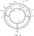
- FIG. 3 is a schematic diagram of scavenge oil pump 143.
- Scavenge oil pump 143 includes a rotating oil groove or plenum 302 circumscribing a rotating scoop tube assembly 304.
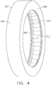
- FIG. 4 is a schematic diagram of rotating oil groove or plenum 302.
- Rotating oil plenum 302 includes a cylinder 306 and two side walls 308 coupled to and extending generally along radial direction R inward from each end of cylinder 306 forming a U-shaped plenum 310 to contain a uniform pool of oil 312.
- Rotating oil plenum 302 is rotationally coupled to LP shaft or spool 136.
- Rotating scoop tube assembly 304 includes a plurality of scoop tubes 314 extending generally along radial direction R outward from centerline 112 into uniform pool of oil 312. Scoop tubes 314 are coupled in flow communication with stationary scavenge oil drain pipe 147 at the bottom of the sump. Rotating scoop tube assembly 304 is rotationally coupled to HP shaft or spool 134.
- scavenge oil collects in sumps and drains into rotating oil plenum 302.
- LP shaft or spool 136 rotates rotating oil plenum 302 with a first angular velocity as indicated by arrow 316.
- Centrifugal force from rotation of rotating oil plenum 302 forms drained scavenges oil into uniform pool of oil 312.
- HP shaft or spool 134 rotates rotating scoop tube assembly 304 with a second angular velocity as indicated by arrow 318.
- First angular velocity 316 rotates in an opposite direction from second angular velocity 318 because HP shaft or spool 134 rotates counter to LP shaft or spool 136.
- Scavenge oil is channeled into scoop tubes 314 which channels scavenge oil into stationary scavenge oil drain pipe147 as indicated by arrows 320. Scavenge oil drain pipe 147 channels oil to scavenge oil system 145 located at the bottom of gas turbine engine 110 (shown in FIG. 1 ).
- rotating oil plenum 302 and rotating scoop tube assembly 304 are configured to rotate in the same direction rather than opposite directions.
- Rotating oil plenum 302 rotates in the direction of a third angular velocity as indicated by arrow 322.
- the rotational direction of second angular velocity 318 and third angular velocity 322 are equal.
- the magnitude of rotational speed of second angular velocity 318 and third angular velocity 322 are unequal to channel scavenge oil into scoop tubes 314.
- rotating oil plenum 302 is configured to rotate and rotating scoop tube assembly 304 is configured to remain stationary.
- Rotating oil plenum 302 rotates in the direction of first angular velocity 316. Rotation of rotating oil plenum 302 channels scavenge oil into scoop tubes 314.
- the above-described pump provides an efficient method for transporting scavenge oil in a gas turbine engine.
- the above-described pump pumps scavenge oil to an inner radius of a gas turbine engine.
- Scavenge oil is channeled aft to a TRF which experiences cooler operating temperatures than TCFs.
- Channeling scavenge oil through a TRF allows reduction of the thickness of the TFC. Reduced TFC strut thickness reduces the weight of the gas turbine engine.
- channeling scavenge oil through a TRF improves the performance of the gas turbine engine.
- channeling scavenge oil through a TRF eliminates the need for cooling air in the TFC to reduce scavenge oil coking.
- Exemplary embodiments of a pump for scavenge oil are described above in detail.
- the pump, and methods of operating such systems and devices are not limited to the specific embodiments described herein, but rather, components of systems and/or steps of the methods may be utilized independently and separately from other components and/or steps described herein.
- the methods may also be used in combination with other systems requiring scavenge oil pumping, and are not limited to practice with only the systems and methods as described herein.
- the exemplary embodiment can be implemented and utilized in connection with many other machinery applications that are currently configured to receive and accept pumps.
- Example methods and apparatus for a pump in a gas turbine engine are described above in detail.
- the apparatus illustrated is not limited to the specific embodiments described herein, but rather, components of each may be utilized independently and separately from other components described herein. Each system component can also be used in combination with other system components.
Landscapes
- Engineering & Computer Science (AREA)
- General Engineering & Computer Science (AREA)
- Mechanical Engineering (AREA)
- Chemical & Material Sciences (AREA)
- Combustion & Propulsion (AREA)
- Structures Of Non-Positive Displacement Pumps (AREA)
- Lubrication Details And Ventilation Of Internal Combustion Engines (AREA)
Applications Claiming Priority (1)
| Application Number | Priority Date | Filing Date | Title |
|---|---|---|---|
| US14/984,372 US10060290B2 (en) | 2015-12-30 | 2015-12-30 | Method and system for centrifugal pump |
Publications (2)
| Publication Number | Publication Date |
|---|---|
| EP3187700A2 true EP3187700A2 (de) | 2017-07-05 |
| EP3187700A3 EP3187700A3 (de) | 2017-08-16 |
Family
ID=57681270
Family Applications (1)
| Application Number | Title | Priority Date | Filing Date |
|---|---|---|---|
| EP16203873.1A Withdrawn EP3187700A3 (de) | 2015-12-30 | 2016-12-13 | Verfahren und system für eine kreiselpumpe |
Country Status (6)
| Country | Link |
|---|---|
| US (1) | US10060290B2 (de) |
| EP (1) | EP3187700A3 (de) |
| JP (1) | JP2017120084A (de) |
| CN (1) | CN106979077B (de) |
| BR (1) | BR102016030862A2 (de) |
| CA (1) | CA2952657A1 (de) |
Cited By (1)
| Publication number | Priority date | Publication date | Assignee | Title |
|---|---|---|---|---|
| EP3453924A1 (de) * | 2017-09-08 | 2019-03-13 | Rolls-Royce plc | Hilfsölversorgungsvorrichtung für eine rotierende komponente |
Families Citing this family (3)
| Publication number | Priority date | Publication date | Assignee | Title |
|---|---|---|---|---|
| US11655731B2 (en) | 2020-02-14 | 2023-05-23 | Pratt & Whitney Canada Corp. | Oil distribution system for gas turbine engine |
| US11492926B2 (en) * | 2020-12-17 | 2022-11-08 | Pratt & Whitney Canada Corp. | Bearing housing with slip joint |
| US11732750B2 (en) * | 2021-03-04 | 2023-08-22 | General Electric Company | Bearing system with independent adaptive stifness support |
Family Cites Families (20)
| Publication number | Priority date | Publication date | Assignee | Title |
|---|---|---|---|---|
| US1216235A (en) | 1914-09-03 | 1917-02-13 | Gen Electric | Scavenging-pump for internal-combustion engines. |
| GB493333A (en) * | 1937-06-04 | 1938-10-06 | Eugene Guy Euston Beaumont | Improvements relating to centrifugal pumps |
| US2376071A (en) * | 1940-08-27 | 1945-05-15 | Miess Fred | Centrifugal pump |
| US2690130A (en) * | 1949-11-19 | 1954-09-28 | Hydrojet Corp | Centrifugal pump unit |
| US2747514A (en) | 1952-07-22 | 1956-05-29 | Edwards Miles Lowell | Scavenge line centrifuge |
| US2974602A (en) * | 1955-01-27 | 1961-03-14 | Borg Warner | Fuel booster pump |
| US4230564A (en) * | 1978-07-24 | 1980-10-28 | Keefer Bowie | Rotary reverse osmosis apparatus and method |
| US4548545A (en) * | 1983-04-04 | 1985-10-22 | Dorr-Oliver Incorporated | Centrifugal pump with deaeration chamber |
| US4468066A (en) * | 1983-05-02 | 1984-08-28 | United Technologies Corporation | Oil capture scoop |
| US4453784A (en) * | 1983-05-02 | 1984-06-12 | United Technologies Corporation | Means for feeding oil between counterrotating shafts |
| US4767281A (en) | 1987-06-04 | 1988-08-30 | Lear Siegler, Inc. | Centrifugal pump system with inlet reservoir |
| US5319920A (en) | 1992-05-28 | 1994-06-14 | General Electric Company | Lubricant supply and return system for the center bearing assembly and the rear bearing assembly of a marine or industrial gas turbine engine |
| CN1179118C (zh) * | 1999-11-08 | 2004-12-08 | 罗桂荣 | 改进的燃气轮机 |
| US7458202B2 (en) | 2004-10-29 | 2008-12-02 | General Electric Company | Lubrication system for a counter-rotating turbine engine and method of assembling same |
| CN201016307Y (zh) * | 2006-11-08 | 2008-02-06 | 沈阳黎明航空发动机(集团)有限责任公司 | 一种燃机机组润滑油和顶轴油供应系统 |
| US8210316B2 (en) | 2006-12-12 | 2012-07-03 | United Technologies Corporation | Oil scavenge system for a gas turbine engine |
| US7931124B2 (en) | 2007-12-12 | 2011-04-26 | United Technologies Corporation | On-demand lubrication system and method for improved flow management and containment |
| PL402185A1 (pl) | 2012-12-21 | 2014-06-23 | General Electric Company | Połączona instalacja ściekowa do silników turbinowych |
| US9915203B2 (en) | 2013-03-15 | 2018-03-13 | Rolls-Royce Corporation | Gas turbine engine lubrication system |
| US9726040B2 (en) * | 2015-03-27 | 2017-08-08 | Pratt & Whitney Canada Corp. | Fluid delivery system for a gas turbine engine |
-
2015
- 2015-12-30 US US14/984,372 patent/US10060290B2/en active Active
-
2016
- 2016-12-13 EP EP16203873.1A patent/EP3187700A3/de not_active Withdrawn
- 2016-12-19 JP JP2016245009A patent/JP2017120084A/ja active Pending
- 2016-12-22 CA CA2952657A patent/CA2952657A1/en not_active Abandoned
- 2016-12-29 BR BR102016030862-3A patent/BR102016030862A2/pt not_active Application Discontinuation
- 2016-12-30 CN CN201611255955.7A patent/CN106979077B/zh active Active
Non-Patent Citations (1)
| Title |
|---|
| None |
Cited By (2)
| Publication number | Priority date | Publication date | Assignee | Title |
|---|---|---|---|---|
| EP3453924A1 (de) * | 2017-09-08 | 2019-03-13 | Rolls-Royce plc | Hilfsölversorgungsvorrichtung für eine rotierende komponente |
| US11085521B2 (en) | 2017-09-08 | 2021-08-10 | Rolls-Royce Plc | Auxiliary oil supply apparatus for a rotating component |
Also Published As
| Publication number | Publication date |
|---|---|
| JP2017120084A (ja) | 2017-07-06 |
| CN106979077B (zh) | 2021-06-25 |
| CN106979077A (zh) | 2017-07-25 |
| BR102016030862A2 (pt) | 2017-12-12 |
| EP3187700A3 (de) | 2017-08-16 |
| CA2952657A1 (en) | 2017-06-30 |
| US20170191378A1 (en) | 2017-07-06 |
| US10060290B2 (en) | 2018-08-28 |
Similar Documents
| Publication | Publication Date | Title |
|---|---|---|
| CN106837552B (zh) | 用于冷却飞行器发动机流体的方法及系统 | |
| US10100736B2 (en) | Gas turbine engine sump heat exchanger | |
| US10890247B2 (en) | Lubrication fluid collection in a gearbox of a gas turbine engine | |
| EP3187724A1 (de) | Verfahren und system für kombinationswärmetauscher | |
| US10830056B2 (en) | Fluid cooling systems for a gas turbine engine | |
| US9677424B2 (en) | Gas turbine engine | |
| CN106917682B (zh) | 燃气涡轮发动机轴承油槽 | |
| EP3176379B1 (de) | Gehäuse zur verwendung in einem turbofantriebwerk und verfahren zur beseitigung von fluid daraus | |
| US10060290B2 (en) | Method and system for centrifugal pump | |
| CA2990788C (en) | Apparatus for a gearbox with multiple scavenge ports | |
| EP3346164B1 (de) | Getriebe mit fluiddamm und öffnungen | |
| US12234748B2 (en) | Gas turbine engine having outlet guide vanes |
Legal Events
| Date | Code | Title | Description |
|---|---|---|---|
| PUAI | Public reference made under article 153(3) epc to a published international application that has entered the european phase |
Free format text: ORIGINAL CODE: 0009012 |
|
| STAA | Information on the status of an ep patent application or granted ep patent |
Free format text: STATUS: THE APPLICATION HAS BEEN PUBLISHED |
|
| AK | Designated contracting states |
Kind code of ref document: A2 Designated state(s): AL AT BE BG CH CY CZ DE DK EE ES FI FR GB GR HR HU IE IS IT LI LT LU LV MC MK MT NL NO PL PT RO RS SE SI SK SM TR |
|
| AX | Request for extension of the european patent |
Extension state: BA ME |
|
| PUAL | Search report despatched |
Free format text: ORIGINAL CODE: 0009013 |
|
| AK | Designated contracting states |
Kind code of ref document: A3 Designated state(s): AL AT BE BG CH CY CZ DE DK EE ES FI FR GB GR HR HU IE IS IT LI LT LU LV MC MK MT NL NO PL PT RO RS SE SI SK SM TR |
|
| AX | Request for extension of the european patent |
Extension state: BA ME |
|
| RIC1 | Information provided on ipc code assigned before grant |
Ipc: F01D 25/20 20060101ALI20170711BHEP Ipc: F01D 25/18 20060101AFI20170711BHEP |
|
| STAA | Information on the status of an ep patent application or granted ep patent |
Free format text: STATUS: REQUEST FOR EXAMINATION WAS MADE |
|
| 17P | Request for examination filed |
Effective date: 20180216 |
|
| RBV | Designated contracting states (corrected) |
Designated state(s): AL AT BE BG CH CY CZ DE DK EE ES FI FR GB GR HR HU IE IS IT LI LT LU LV MC MK MT NL NO PL PT RO RS SE SI SK SM TR |
|
| STAA | Information on the status of an ep patent application or granted ep patent |
Free format text: STATUS: EXAMINATION IS IN PROGRESS |
|
| 17Q | First examination report despatched |
Effective date: 20190801 |
|
| GRAP | Despatch of communication of intention to grant a patent |
Free format text: ORIGINAL CODE: EPIDOSNIGR1 |
|
| STAA | Information on the status of an ep patent application or granted ep patent |
Free format text: STATUS: GRANT OF PATENT IS INTENDED |
|
| INTG | Intention to grant announced |
Effective date: 20200731 |
|
| STAA | Information on the status of an ep patent application or granted ep patent |
Free format text: STATUS: THE APPLICATION IS DEEMED TO BE WITHDRAWN |
|
| 18D | Application deemed to be withdrawn |
Effective date: 20201211 |