EP3189000B1 - Ventil zur abgabe und eventuelle belüftung einer flüssigkeit - Google Patents
Ventil zur abgabe und eventuelle belüftung einer flüssigkeit Download PDFInfo
- Publication number
- EP3189000B1 EP3189000B1 EP14758580.6A EP14758580A EP3189000B1 EP 3189000 B1 EP3189000 B1 EP 3189000B1 EP 14758580 A EP14758580 A EP 14758580A EP 3189000 B1 EP3189000 B1 EP 3189000B1
- Authority
- EP
- European Patent Office
- Prior art keywords
- valve
- liquid
- control member
- circumferential
- housing
- Prior art date
- Legal status (The legal status is an assumption and is not a legal conclusion. Google has not performed a legal analysis and makes no representation as to the accuracy of the status listed.)
- Not-in-force
Links
- 239000007788 liquid Substances 0.000 title claims description 136
- 230000006835 compression Effects 0.000 claims description 10
- 238000007906 compression Methods 0.000 claims description 10
- 238000007789 sealing Methods 0.000 claims description 5
- 238000005273 aeration Methods 0.000 description 20
- 235000014101 wine Nutrition 0.000 description 18
- 235000013361 beverage Nutrition 0.000 description 10
- 238000004806 packaging method and process Methods 0.000 description 7
- 230000000694 effects Effects 0.000 description 6
- 239000011521 glass Substances 0.000 description 5
- 238000005276 aerator Methods 0.000 description 4
- 230000005484 gravity Effects 0.000 description 3
- CURLTUGMZLYLDI-UHFFFAOYSA-N Carbon dioxide Chemical compound O=C=O CURLTUGMZLYLDI-UHFFFAOYSA-N 0.000 description 2
- LFQSCWFLJHTTHZ-UHFFFAOYSA-N Ethanol Chemical compound CCO LFQSCWFLJHTTHZ-UHFFFAOYSA-N 0.000 description 2
- 230000015572 biosynthetic process Effects 0.000 description 2
- 239000012530 fluid Substances 0.000 description 2
- VNWKTOKETHGBQD-UHFFFAOYSA-N methane Chemical compound C VNWKTOKETHGBQD-UHFFFAOYSA-N 0.000 description 2
- 238000000034 method Methods 0.000 description 2
- 238000005507 spraying Methods 0.000 description 2
- XLYOFNOQVPJJNP-UHFFFAOYSA-N water Substances O XLYOFNOQVPJJNP-UHFFFAOYSA-N 0.000 description 2
- ZAMOUSCENKQFHK-UHFFFAOYSA-N Chlorine atom Chemical compound [Cl] ZAMOUSCENKQFHK-UHFFFAOYSA-N 0.000 description 1
- NINIDFKCEFEMDL-UHFFFAOYSA-N Sulfur Chemical compound [S] NINIDFKCEFEMDL-UHFFFAOYSA-N 0.000 description 1
- 239000005864 Sulphur Substances 0.000 description 1
- 239000002253 acid Substances 0.000 description 1
- 150000007513 acids Chemical class 0.000 description 1
- 230000009471 action Effects 0.000 description 1
- 235000019568 aromas Nutrition 0.000 description 1
- QVGXLLKOCUKJST-UHFFFAOYSA-N atomic oxygen Chemical compound [O] QVGXLLKOCUKJST-UHFFFAOYSA-N 0.000 description 1
- 230000009286 beneficial effect Effects 0.000 description 1
- 230000005540 biological transmission Effects 0.000 description 1
- 239000001569 carbon dioxide Substances 0.000 description 1
- 229910002092 carbon dioxide Inorganic materials 0.000 description 1
- 239000000460 chlorine Substances 0.000 description 1
- 229910052801 chlorine Inorganic materials 0.000 description 1
- 239000000470 constituent Substances 0.000 description 1
- 230000008020 evaporation Effects 0.000 description 1
- 238000001704 evaporation Methods 0.000 description 1
- 239000000796 flavoring agent Substances 0.000 description 1
- 235000019634 flavors Nutrition 0.000 description 1
- 230000002431 foraging effect Effects 0.000 description 1
- 235000015203 fruit juice Nutrition 0.000 description 1
- 239000001257 hydrogen Substances 0.000 description 1
- 229910052739 hydrogen Inorganic materials 0.000 description 1
- 125000004435 hydrogen atom Chemical class [H]* 0.000 description 1
- 239000004615 ingredient Substances 0.000 description 1
- 230000007246 mechanism Effects 0.000 description 1
- 239000000203 mixture Substances 0.000 description 1
- 230000003647 oxidation Effects 0.000 description 1
- 238000007254 oxidation reaction Methods 0.000 description 1
- 239000001301 oxygen Substances 0.000 description 1
- 229910052760 oxygen Inorganic materials 0.000 description 1
- 230000008569 process Effects 0.000 description 1
- 230000001737 promoting effect Effects 0.000 description 1
- 230000009467 reduction Effects 0.000 description 1
- 235000015096 spirit Nutrition 0.000 description 1
- LSNNMFCWUKXFEE-UHFFFAOYSA-L sulfite Chemical compound [O-]S([O-])=O LSNNMFCWUKXFEE-UHFFFAOYSA-L 0.000 description 1
- -1 sulphite) Chemical class 0.000 description 1
- 229920001864 tannin Polymers 0.000 description 1
- 239000001648 tannin Substances 0.000 description 1
- 235000018553 tannin Nutrition 0.000 description 1
Images



Classifications
-
- B—PERFORMING OPERATIONS; TRANSPORTING
- B67—OPENING, CLOSING OR CLEANING BOTTLES, JARS OR SIMILAR CONTAINERS; LIQUID HANDLING
- B67D—DISPENSING, DELIVERING OR TRANSFERRING LIQUIDS, NOT OTHERWISE PROVIDED FOR
- B67D1/00—Apparatus or devices for dispensing beverages on draught
- B67D1/0042—Details of specific parts of the dispensers
- B67D1/0043—Mixing devices for liquids
- B67D1/0044—Mixing devices for liquids for mixing inside the dispensing nozzle
- B67D1/0045—Venturi arrangements; Aspirators; Eductors
-
- B—PERFORMING OPERATIONS; TRANSPORTING
- B01—PHYSICAL OR CHEMICAL PROCESSES OR APPARATUS IN GENERAL
- B01F—MIXING, e.g. DISSOLVING, EMULSIFYING OR DISPERSING
- B01F23/00—Mixing according to the phases to be mixed, e.g. dispersing or emulsifying
- B01F23/20—Mixing gases with liquids
- B01F23/23—Mixing gases with liquids by introducing gases into liquid media, e.g. for producing aerated liquids
- B01F23/232—Mixing gases with liquids by introducing gases into liquid media, e.g. for producing aerated liquids using flow-mixing means for introducing the gases, e.g. baffles
- B01F23/2326—Mixing gases with liquids by introducing gases into liquid media, e.g. for producing aerated liquids using flow-mixing means for introducing the gases, e.g. baffles adding the flowing main component by suction means, e.g. using an ejector
-
- B—PERFORMING OPERATIONS; TRANSPORTING
- B01—PHYSICAL OR CHEMICAL PROCESSES OR APPARATUS IN GENERAL
- B01F—MIXING, e.g. DISSOLVING, EMULSIFYING OR DISPERSING
- B01F23/00—Mixing according to the phases to be mixed, e.g. dispersing or emulsifying
- B01F23/20—Mixing gases with liquids
- B01F23/23—Mixing gases with liquids by introducing gases into liquid media, e.g. for producing aerated liquids
- B01F23/236—Mixing gases with liquids by introducing gases into liquid media, e.g. for producing aerated liquids specially adapted for aerating or carbonating beverages
-
- B—PERFORMING OPERATIONS; TRANSPORTING
- B01—PHYSICAL OR CHEMICAL PROCESSES OR APPARATUS IN GENERAL
- B01F—MIXING, e.g. DISSOLVING, EMULSIFYING OR DISPERSING
- B01F25/00—Flow mixers; Mixers for falling materials, e.g. solid particles
- B01F25/105—Mixing heads, i.e. compact mixing units or modules, using mixing valves for feeding and mixing at least two components
- B01F25/1051—Mixing heads, i.e. compact mixing units or modules, using mixing valves for feeding and mixing at least two components of the mixing valve type
-
- B—PERFORMING OPERATIONS; TRANSPORTING
- B01—PHYSICAL OR CHEMICAL PROCESSES OR APPARATUS IN GENERAL
- B01F—MIXING, e.g. DISSOLVING, EMULSIFYING OR DISPERSING
- B01F25/00—Flow mixers; Mixers for falling materials, e.g. solid particles
- B01F25/30—Injector mixers
- B01F25/31—Injector mixers in conduits or tubes through which the main component flows
- B01F25/312—Injector mixers in conduits or tubes through which the main component flows with Venturi elements; Details thereof
- B01F25/3124—Injector mixers in conduits or tubes through which the main component flows with Venturi elements; Details thereof characterised by the place of introduction of the main flow
- B01F25/31242—Injector mixers in conduits or tubes through which the main component flows with Venturi elements; Details thereof characterised by the place of introduction of the main flow the main flow being injected in the central area of the venturi, creating an aspiration in the circumferential part of the conduit
-
- B—PERFORMING OPERATIONS; TRANSPORTING
- B67—OPENING, CLOSING OR CLEANING BOTTLES, JARS OR SIMILAR CONTAINERS; LIQUID HANDLING
- B67D—DISPENSING, DELIVERING OR TRANSFERRING LIQUIDS, NOT OTHERWISE PROVIDED FOR
- B67D1/00—Apparatus or devices for dispensing beverages on draught
- B67D1/0003—Apparatus or devices for dispensing beverages on draught the beverage being a single liquid
- B67D1/0004—Apparatus or devices for dispensing beverages on draught the beverage being a single liquid the beverage being stored in a container, e.g. bottle, cartridge, bag-in-box, bowl
-
- B—PERFORMING OPERATIONS; TRANSPORTING
- B67—OPENING, CLOSING OR CLEANING BOTTLES, JARS OR SIMILAR CONTAINERS; LIQUID HANDLING
- B67D—DISPENSING, DELIVERING OR TRANSFERRING LIQUIDS, NOT OTHERWISE PROVIDED FOR
- B67D1/00—Apparatus or devices for dispensing beverages on draught
- B67D1/0042—Details of specific parts of the dispensers
- B67D1/0081—Dispensing valves
-
- B—PERFORMING OPERATIONS; TRANSPORTING
- B67—OPENING, CLOSING OR CLEANING BOTTLES, JARS OR SIMILAR CONTAINERS; LIQUID HANDLING
- B67D—DISPENSING, DELIVERING OR TRANSFERRING LIQUIDS, NOT OTHERWISE PROVIDED FOR
- B67D1/00—Apparatus or devices for dispensing beverages on draught
- B67D1/08—Details
- B67D1/12—Flow or pressure control devices or systems, e.g. valves, gas pressure control, level control in storage containers
- B67D1/14—Reducing valves or control taps
- B67D1/1405—Control taps
- B67D1/145—Control taps comprising a valve shutter movable in a direction perpendicular to the valve seat
- B67D1/1455—Control taps comprising a valve shutter movable in a direction perpendicular to the valve seat the valve shutter being opened in the same direction as the liquid flow
-
- B—PERFORMING OPERATIONS; TRANSPORTING
- B67—OPENING, CLOSING OR CLEANING BOTTLES, JARS OR SIMILAR CONTAINERS; LIQUID HANDLING
- B67D—DISPENSING, DELIVERING OR TRANSFERRING LIQUIDS, NOT OTHERWISE PROVIDED FOR
- B67D3/00—Apparatus or devices for controlling flow of liquids under gravity from storage containers for dispensing purposes
- B67D3/04—Liquid-dispensing taps or cocks adapted to seal and open tapping holes of casks, e.g. for beer
- B67D3/043—Liquid-dispensing taps or cocks adapted to seal and open tapping holes of casks, e.g. for beer with a closing element having a linear movement, in a direction perpendicular to the seat
- B67D3/044—Liquid-dispensing taps or cocks adapted to seal and open tapping holes of casks, e.g. for beer with a closing element having a linear movement, in a direction perpendicular to the seat and venting means operated automatically with the tap
-
- B—PERFORMING OPERATIONS; TRANSPORTING
- B01—PHYSICAL OR CHEMICAL PROCESSES OR APPARATUS IN GENERAL
- B01F—MIXING, e.g. DISSOLVING, EMULSIFYING OR DISPERSING
- B01F2101/00—Mixing characterised by the nature of the mixed materials or by the application field
- B01F2101/06—Mixing of food ingredients
- B01F2101/16—Mixing wine or other alcoholic beverages; Mixing ingredients thereof
- B01F2101/17—Aeration of wine
-
- B—PERFORMING OPERATIONS; TRANSPORTING
- B01—PHYSICAL OR CHEMICAL PROCESSES OR APPARATUS IN GENERAL
- B01F—MIXING, e.g. DISSOLVING, EMULSIFYING OR DISPERSING
- B01F23/00—Mixing according to the phases to be mixed, e.g. dispersing or emulsifying
- B01F23/20—Mixing gases with liquids
- B01F23/23—Mixing gases with liquids by introducing gases into liquid media, e.g. for producing aerated liquids
- B01F23/237—Mixing gases with liquids by introducing gases into liquid media, e.g. for producing aerated liquids characterised by the physical or chemical properties of gases or vapours introduced in the liquid media
- B01F23/2376—Mixing gases with liquids by introducing gases into liquid media, e.g. for producing aerated liquids characterised by the physical or chemical properties of gases or vapours introduced in the liquid media characterised by the gas being introduced
- B01F23/23761—Aerating, i.e. introducing oxygen containing gas in liquids
- B01F23/237611—Air
-
- B—PERFORMING OPERATIONS; TRANSPORTING
- B01—PHYSICAL OR CHEMICAL PROCESSES OR APPARATUS IN GENERAL
- B01F—MIXING, e.g. DISSOLVING, EMULSIFYING OR DISPERSING
- B01F23/00—Mixing according to the phases to be mixed, e.g. dispersing or emulsifying
- B01F23/20—Mixing gases with liquids
- B01F23/23—Mixing gases with liquids by introducing gases into liquid media, e.g. for producing aerated liquids
- B01F23/237—Mixing gases with liquids by introducing gases into liquid media, e.g. for producing aerated liquids characterised by the physical or chemical properties of gases or vapours introduced in the liquid media
- B01F23/2376—Mixing gases with liquids by introducing gases into liquid media, e.g. for producing aerated liquids characterised by the physical or chemical properties of gases or vapours introduced in the liquid media characterised by the gas being introduced
- B01F23/23762—Carbon dioxide
- B01F23/237621—Carbon dioxide in beverages
-
- B—PERFORMING OPERATIONS; TRANSPORTING
- B01—PHYSICAL OR CHEMICAL PROCESSES OR APPARATUS IN GENERAL
- B01F—MIXING, e.g. DISSOLVING, EMULSIFYING OR DISPERSING
- B01F25/00—Flow mixers; Mixers for falling materials, e.g. solid particles
- B01F25/30—Injector mixers
- B01F25/31—Injector mixers in conduits or tubes through which the main component flows
- B01F25/312—Injector mixers in conduits or tubes through which the main component flows with Venturi elements; Details thereof
- B01F25/3125—Injector mixers in conduits or tubes through which the main component flows with Venturi elements; Details thereof characteristics of the Venturi parts
- B01F25/31251—Throats
- B01F25/312512—Profiled, grooved, ribbed throat, or being provided with baffles
-
- B—PERFORMING OPERATIONS; TRANSPORTING
- B67—OPENING, CLOSING OR CLEANING BOTTLES, JARS OR SIMILAR CONTAINERS; LIQUID HANDLING
- B67D—DISPENSING, DELIVERING OR TRANSFERRING LIQUIDS, NOT OTHERWISE PROVIDED FOR
- B67D1/00—Apparatus or devices for dispensing beverages on draught
- B67D1/0001—Apparatus or devices for dispensing beverages on draught by squeezing collapsible or flexible storage containers
Definitions
- the invention firstly relates to a valve for dispensing a liquid in accordance with the preamble of claim 1.
- a valve of this type may be useful in combination with a beverage dispenser in which beverages that are contained and sold in bag-in-box packagings (BIB) are used (but it is not limited to such an application).
- This type of packaging is well known on the market and is used for many kinds of beverages like wine, fruit juice, water, spirits and others. Beverages stored in BIB have in common that they are non-carbonised because the packaging cannot be used under pressure. For wine this means that only 'still' wines can be stored. Another characteristic of wine stored in BIB packaging is that the packaging cannot be used for aging the wine to improve its quality, like in glass bottles. A typical wine stored in BIB packaging is in most cases a relative young wine.
- a known technique for letting wine breath is decanting in a decanter or in a glass, or by aeration, which involves bringing wine into contact with air by mixing wine with little air bubbles during the pouring process. Aeration triggers evaporation and oxidation of the above mentioned components, which results in subtle but noticeable softening of the taste and an enhancement of the aromas. Aeration also may increase the oxygen saturation in liquids.
- Aeration can also be beneficial for other beverages.
- Water for instance, can contain gasses like hydrogen sulphur, chlorine, methane or carbon dioxide. Aeration promotes the release of these gasses and improves the taste and overall quality.
- aeration improves the overall quality of the beverages.
- aeration to the contrary causes a reduction of the more appreciated bouquet of wine or loss of subtle flavour characteristics.
- aerators that can be used to aerate wine or other liquids. Some can be placed on a bottle and aerate during pouring out, whereas others are placed above a glass and aerate when wine is poured into the aerator that releases aerated wine in the glass. Examples of both types are disclosed in AU-A-2013204096 , CN-Y-201372191 , GB2473744 , CN-U-202346740 , CN-U-201958676 and CN-U-202269919 . These aerators all use the Venturi principle for mixing fluid with air. This is a proven concept that works very well with low pressure and flow of the fluid and air.
- a valve in accordance with the preamble of claim 1 is disclosed in document US2014/091107 , in which the opening and closing of the air passage is controlled by a separate aeration switch.
- an object of the present invention to provide an improved valve for dispensing a liquid with an integrated, switchable aerating function, so the user can choose whether to aerate or not during dispensing.
- valve is characterized as set forth in claim 1.
- valve In the first position of the control member the valve is closed and no liquid is dispensed. In the second position of the control member the valve is open, but the air passage between the valve member and control member is still closed and liquid is dispensed without aeration. In the third position both the valve and air passage are open and liquid is dispensed with aeration. Air enters the air passage from the outside (surroundings) of the valve and mixes with the liquid at the junction between the air passage and the internal liquid passage within the valve.
- valve member and housing have cooperating abutment means for defining the open position of the valve member.
- abutment means allow an easy operation of the valve by a user.
- the housing may comprise a circumferential step whereas the valve member then comprises a circumferential protrusion for cooperation with said circumferential step.
- valve member rests in its closed position (engaging the valve seat) when the valve is not manipulated by a user
- control member is biased to its first position
- control member may be biased by spring means, such as a compression spring, positioned between the housing and the control member.
- spring means such as a compression spring
- the pressure of the liquid on the valve member and/or the gravity force on the valve member will be sufficient to move the valve member towards its open position. If this, however, cannot be assured, it is conceivable that the valve member is biased to its open position, wherein the bias on the valve member is less than the bias on the control member. The difference in bias is needed to assure that the valve member does not move towards its open position before the control member is operated.
- valve member may be biased by spring means, such as a compression spring, positioned between the housing and the valve member.
- control member is provided with at least one operating tab protruding outwardly through an opening in the housing. This operating tab may be engaged by a finger of a user (or by another external operating mechanism) to move the control member.
- the valve is provided with two operating tabs positioned diametrically opposite to each other, leading to symmetrical forces and thus the need for lower operating forces.
- the valve member is provided with a liquid collector which in a liquid tight and movable manner engages the valve seat and which defines a first inner liquid channel that in the open position of the valve member communicates with a valve passage through the valve seat.
- a liquid collector assures that the liquid passing the valve member reaches the place where the air passage ends.
- the liquid collector has circumferential inner and outer surfaces
- the control member defines a second inner liquid channel communicating with the first inner liquid channel of the liquid collector and has a circumferential inner surface
- the at least one air passage is defined as an annular channel that extends between the circumferential outer surface of the liquid collector and the circumferential inner surface of the control member and that debouches into the second inner liquid channel, wherein in the first and second positions of the control member the circumferential inner surface of the control member in a sealing manner engages the circumferential outer surface of the liquid collector for closing said annular channel, whereas in the third position of the control member the circumferential inner surface of the control member disengages the circumferential outer surface of the liquid collector for opening said annular channel.
- the liquid flowing out of the first inner liquid channel of the liquid collector into the second inner liquid channel causes a Venturi effect which in the third position of the control member causes air to flow through the air passage towards the second inner liquid channel for a mixing with the liquid leaving the liquid collector.
- the mixing may further be promoted when the annular channel in the region where it debouches into the second inner liquid channel is provided with turbulators.
- the turbulators may be positioned immediately before said narrowed throat. Behind the throat the second inner liquid channel again widens, leading to an expansion of the air/liquid mixture (generally leading to a better mixing effect).
- said turbulators may comprise a circumferential step in the circumferential inner surface of the control member.
- the air arriving from the air passage (the annular channel) impinges on said turbulators causing turbulence improving the mixing of liquid and air bubbles.
- the outlet of the valve may be provided with a restrictor for forming a well-defined jet of liquid spraying out of the valve.
- connector means are provided at its inlet for allowing a liquid tight connection between the valve and a spigot or spout of a liquid reservoir, such as a flexible bag.
- a liquid reservoir such as a flexible bag.
- the invention in a second aspect, relates to a liquid dispensing device for use with a flexible bag containing said liquid and having a spigot or spout connected thereto, which device comprises a housing for receiving the bag, which housing is provided with a receiving means for receiving the spigot or spout.
- the receiving means comprises a valve according to the invention of which the inlet is provided with connector means adapted for realising a liquid tight connection between the valve and the spigot or spout of the flexible bag.
- the valve is provided in an upper part of the housing and wherein the housing further is provided with a support member for the flexible bag, which support member is movable between a lowermost position remote from the valve for supporting a full bag and an uppermost position near to the valve for supporting a substantially empty bag.
- valve is located at such a high level that for filling a glass with the liquid (beverage) the device does not have to be positioned on an elevated support nor has to be lifted by a user.
- the support member has an inclined upper support surface sloping down to the side of the valve. This ensures that the bag is completely emptied.
- the valve according to the invention offers a number of advantages. It may act as a normal valve that opens or closes a channel for liquids such as beverages and it can control and provide an aeration function. In some embodiments it further offers a universal interface for connection to a liquid source (i.e. a spigot or spout of a bag in box packaging containing a beverage such as wine).
- a liquid source i.e. a spigot or spout of a bag in box packaging containing a beverage such as wine.
- the valve according to the invention further is aimed to offer a compact size, to be easy and cheap to make, fit for wine and other beverages, whereas further the standard valve function and the aerate function are combined in one actuating action.
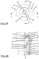
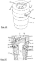
- valve for dispensing a liquid according to the invention.
- the valve comprises a housing with a housing top 1 and a lower housing 2.
- the housing top 1 internally is provided with a valve seat 5 which cooperates with a central cone 7 of a valve member 6 which (as will appear below) is movable between a closed position engaging the valve seat 5 for closing a valve passage 8 (which also is part of the internal liquid passage) and an open position disengaging the valve seat 5 for opening the valve passage 8.
- the valve member 6 is provided with a liquid collector 9 which in a movable manner engages the outer face of the valve seat 5 (in the illustrated embodiment the liquid collector 9 engages the outside of the valve seat 5 not directly, but indirectly through the valve member 6) and which defines a first inner liquid channel 10 (also being part of the internal liquid passage) that in the open position of the valve member 6 (cone 7 disengaging the valve seat 5) communicates with the valve passage 8 through the valve seat 5.
- a liquid collector 9 which in a movable manner engages the outer face of the valve seat 5 (in the illustrated embodiment the liquid collector 9 engages the outside of the valve seat 5 not directly, but indirectly through the valve member 6) and which defines a first inner liquid channel 10 (also being part of the internal liquid passage) that in the open position of the valve member 6 (cone 7 disengaging the valve seat 5) communicates with the valve passage 8 through the valve seat 5.
- the valve further comprises a control member 11 for controlling the movement of the valve member 6 between its closed and open positions.
- the control member 11 is movable between a first position in which it engages the valve member 6 for keeping it in its closed position (central cone 7 engaging the valve seat 5), a second position in which the valve member 6 is in its open position (central cone 7 disengaging the valve seat 5) but still is in engagement with the control member 11 and a third position in which the valve member 6 also is in its open position and further the liquid collector 9 is out of engagement with the control member 11, such that in this third position at least one air passage is opened for connecting the outside of the valve with the internal liquid passage.
- the lower housing 2 comprises an internal circumferential step 12 cooperating with a circumferential protrusion 37 (of the liquid collector 9 of the valve member 6) for defining the open position of the valve member.
- the control member 11 is biased to its first position (for closing the valve member) by a compression spring 13 positioned between the lower housing 2 and the control member 11.
- valve member 6 also may be biased to its open position by a compression spring 14 positioned between the housing top 1 and the valve member 6 (or liquid collector 9).
- a compression spring 14 positioned between the housing top 1 and the valve member 6 (or liquid collector 9).
- the bias on the valve member 6 (or liquid collector 9) is less than the bias on the control member 11.
- the control member 11 is provided with two operating tabs 15 positioned diametrically opposite to each other and protruding outwardly through corresponding openings 16 in the lower housing 2.
- the liquid collector 9 has circumferential inner and outer surfaces 17 and 18 (see figures 2C and 3C ) respectively (which in this embodiment taper in a downward direction).
- the inner surface 17 thus defines a narrowing shape of the first inner liquid channel 10.
- the control member 11 defines a second inner liquid channel 19 (also defining part of the internal liquid passage of the valve) communicating with the first inner liquid channel 10 of the liquid collector 9.
- the control member 11 further has a circumferential inner surface 20 (in this embodiment likewise tapering) and an annular tapering channel 21 extends between the circumferential outer surface 18 of the liquid collector 9 and the circumferential inner surface 20 of the control member 11. This channel 21 debouches into the second inner liquid channel 19, just below the lower end of the liquid collector 9.
- turbulators In the region where the annular channel 21 debouches into the second inner liquid channel 19, it is provided with turbulators. These turbulators are shaped as a circumferential step 22 in the circumferential inner surface 20 of the control member 11. Further it is clearly visible that the second inner liquid channel 19 of the control member 11 has a narrowed throat 23 in the region where the annular tapering channel 21 debouches therein. The turbulators (step 22) are positioned immediately before (above) said narrowed throat 23.
- the circumferential inner surface 20 of the control member 11 is provided with longitudinal grooves 24 and the outlet 4 of the valve is surrounded by a restrictor 25.
- a restrictor 25 At the inlet 3 of the valve connector means (for example a thread 26) are provided for allowing a liquid tight connection between the valve and a spigot or spout of a liquid reservoir, such as a flexible bag.
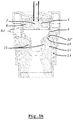
- the valve operates in the following manner: in the starting position ( figure 3A ) of the valve, the control member 11 is kept in its first position by the compression spring 13 in which a horizontally extending part 20' of the circumferential inner surface 20 of the control member 11 in a sealing manner engages the circumferential outer surface 18 of the liquid collector 9 for closing the annular tapering channel 21. Further the valve member 6 with its central cone 7 is kept in engagement with the valve seat 5 for keeping the valve in its closed position, notwithstanding any liquid pressure P (or gravity).
- valve member 11 When the control member 11 (by pressing downwards the operating tabs 15) is moved down against the force of compression spring 13 (over distance h 1 ) towards its second position ( figure 3B ) in which step 12 of the lower housing 2 engages protrusion 37 of the valve member 6, the valve member 6 with liquid collector 9 will move to its open position in which the central cone 7 has disengaged the valve seat 5 and liquid can flow through the valve passage 8, the first inner liquid channel 10 in the liquid collector 9 and the second liquid channel 19 in the control member 11 towards the outlet 4. In this position the part 20' of the circumferential inner surface 20 of the control member 11 still engages the circumferential outer surface 18 of the liquid collector 9 in a sealing manner for closing the annular tapering channel 21. Thus, the valve is in a position for dispensing the liquid without aeration.
- valve member 6 may occur through gravity or the pressure of the liquid P at the inlet 3, but may also be aided by the compression spring 14, if provided.
- the air arriving via the channel 21 impinges on the circumferential step 22 for increasing the mixing effect.
- the liquid spraying out of the lower end 30 of the tapering first liquid channel 10 of the liquid collector 9 causes suction through a Venturi effect for sucking in the air through the channel 21 and a mixing will occur between liquid and air, leading to an aeration of the liquid.
- the lower part of the grooves 24 facilitate the transport of air bubbles that are formed where the liquid and air meet.
- the number, size and orientation of the grooves may vary.
- the distance h 1 defines the distance over which the control member 11 moves between its first and second positions
- the distance h 2 defines the distance over which the control member 11 moves between its second and third positions.
- FIG 4 illustrates a liquid dispensing device for use with a flexible bag containing said liquid and having a spigot or spout 32 connected thereto.
- This device comprises a housing 33 for receiving the bag, which housing is provided with a valve 34 according to the present invention of which the inlet 3 is provided with connector means (not shown in detail here, but for example embodied as a thread 26 as shown in figure 2C and 3D) adapted for realising a liquid tight connection between the valve 34 and the spigot or spout 32 of the flexible bag 31.
- control member of the valve 34 is caused by an operating lever 36 which may be manipulated (for example rotated) manually and which by transmission means not indicated in detail, is connected to the control member.
- the valve 34 is provided in the housing 33 and the housing further is provided with a support member 35 for the flexible bag, which support member 35 is movable between a lowermost position remote from the valve 34 for supporting a full bag and an uppermost position (illustrated in figure 4 ) near to the valve for supporting a substantially empty bag.
- the support member 35 has an inclined upper support surface sloping down to the side of the valve 34, such that it is assured that almost all liquid will reach the valve 34.
- FIGS 5A-5C an alternative embodiment of the valve is shown in three different positions in correspondence with figures 3A-3C (closed, open without aeration and open with aeration, respectively).
- This alternative embodiment basically has the same design as the previous embodiment, apart from a few differences of which the three most important ones are described below.
- the liquid collector 9 engages the valve seat 5 through a deformable seal member 39.
- This seal member 39 with an outer part 39' is attached to the liquid collector 9 and with an inner part 39" is attached to the valve seat 5.
- These outer and inner parts 39',39" are connected by a flexible web 40 allowing the relative movement between these outer and inner parts and thus between the liquid collector 9 and valve seat 5.
- the seal member 39 also may function in a manner similar to compression spring 14 illustrated in figure 2C .
- the overall shape of the internal liquid passage has slightly changed for improving the Venturi effect.
- Such changes of the shape may be reflected in features such as, for example, different angles and distances between, and different diameters of parts.
Landscapes
- Chemical & Material Sciences (AREA)
- Chemical Kinetics & Catalysis (AREA)
- Engineering & Computer Science (AREA)
- Mechanical Engineering (AREA)
- Devices For Dispensing Beverages (AREA)
- Containers And Packaging Bodies Having A Special Means To Remove Contents (AREA)
- Closures For Containers (AREA)
Claims (24)
- Ventil zum Ausgeben einer Flüssigkeit, aufweisend ein Gehäuse (1; 2), eine innere Flüssigkeitspassage (8; 10; 19), die sich durch das Gehäuse erstreckt zwischen einem Einlass (3) und einem Auslass (4), einen Ventilsitz (5), ein Ventilelement (6; 9), welches bewegbar ist zwischen einer Geschlossen-Position, in Eingriff-stehend mit dem Ventilsitz, zum Schließen der Flüssigkeitspassage, und einer Offen-Position, nicht in Eingriff-stehend mit dem Ventilsitz, zum Öffnen der Flüssigkeitspassage, und Steuermittel, welche die Bewegung des Ventilelements zwischen dessen Geschlossen-Position und dessen Offen-Position steuern, wobei die Steuermittel aufweisen ein Steuerelement (11), welches bewegbar ist zwischen einer ersten Position, in welcher es mit dem Ventilelement (6; 9) im Eingriff steht zum Halten desselben in dessen Geschlossen-Position, und einer zweiten Position, in welcher das Ventilelement in dessen Offen-Position ist, aber noch in Eingriff mit dem Steuerelement ist, wobei wenigstens eine Luftpassage (21) zwischen dem Ventilelement (6; 9) und dem Steuerelement (11) definiert ist zum Verbinden der Außenseite des Ventils mit der inneren Flüssigkeitspassage (8; 10; 19), dadurch gekennzeichnet, dass das Steuerelement (11) auch zu einer dritten Position bewegbar ist, in welcher das Ventilelement in seiner Offen-Position und nicht in Eingriff mit dem Steuerelement ist, und wobei die wenigstens eine Luftpassage (21) in der ersten und der zweiten Position des Steuerelements (11) geschlossen ist und in der dritten Position des Steuerelements geöffnet ist.
- Ventil gemäß Anspruch 1, wobei das Ventilelement (6; 9) und das Gehäuse (1; 2) zusammenwirkende Anschlagmittel (37; 12) haben zum Definieren der Offen-Position des Ventilelements.
- Ventil gemäß Anspruch 2, wobei das Gehäuse (1; 2) aufweist eine umfängliche Schulter (12), wobei das Ventilelement (6; 9) aufweist einen umfänglichen Vorsprung (37) zum Zusammenwirken mit der umfänglichen Schulter.
- Ventil gemäß irgendeinem der vorhergehenden Ansprüche, wobei das Steuerelement (11) zu seiner ersten Position hin vorgespannt ist.
- Ventil gemäß Anspruch 4, wobei das Steuerelement (11) durch ein Federmittel (13) vorgespannt ist, das zwischen dem Gehäuse (1; 2) und dem Steuerelement positioniert ist.
- Ventil gemäß Anspruch 5, wobei das Federmittel (13) eine Druckfeder ist.
- Ventil gemäß irgendeinem der Ansprüche 4-6, wobei das Ventilelement (6; 9) zu seiner Offen-Position hin vorgespannt ist, wobei die Vorspannung auf das Ventilelement kleiner ist als die Vorspannung auf das Steuerelement.
- Ventil gemäß Anspruch 7, wobei das Ventilelement (6; 9) durch ein Federmittel (14) vorgespannt ist, das zwischen dem Gehäuse (1; 2) und dem Ventilelement positioniert ist.
- Ventil gemäß Anspruch 8, wobei das Federmittel (14) eine Druckfeder ist.
- Ventil gemäß irgendeinem der vorhergehenden Ansprüche, wobei das Steuerelement (11) mit wenigstens einem Betätigungs-Tab (15) versehen ist, welcher durch eine Öffnung (16) in dem Gehäuse (1; 2) hindurch nach außen vorsteht.
- Ventil gemäß Anspruch 10, versehen mit zwei Betätigungs-Tabs (15), die diametral gegenüberliegend zueinander positioniert sind.
- Ventil gemäß irgendeinem der vorhergehenden Ansprüche, wobei das Ventilelement (6; 9) mit einem Flüssigkeitssammler (9) versehen ist, der in einer flüssigkeitsdichten und bewegbaren Weise mit dem Ventilsitz (5) im Eingriff steht und welcher einen ersten inneren Flüssigkeitskanal (10) definiert, der in der Offen-Position des Ventilelements mit einer Ventilpassage (8) durch den Ventilsitz (5) hindurch kommuniziert.
- Ventil gemäß Anspruch 12, wobei der Flüssigkeitssammler (9) eine umfängliche innere (17) und eine umfängliche äußere (18) Fläche hat, wobei das Steuerelement (11) einen zweiten inneren Flüssigkeitskanal (19) definiert, der mit dem ersten inneren Flüssigkeitskanal (10) des Flüssigkeitssammlers (9) kommuniziert, und eine umfängliche innere Fläche (20) hat, wobei die wenigstens eine Luftpassage (21) als ein ringförmiger Kanal definiert ist, der sich zwischen der umfänglichen äußeren Fläche (18) des Flüssigkeitssammlers (9) und der umfänglichen inneren Fläche (20) des Steuerelements (11) erstreckt und der in den zweiten inneren Flüssigkeitskanal (19) ausmündet, wobei in der ersten und der zweiten Position des Steuerelements die umfängliche innere Fläche (20) des Steuerelements in einer dichten Weise mit der umfänglichen äußeren Fläche (18) des Flüssigkeitssammlers in Eingriff steht zum Schließen des ringförmigen Kanals (21), wobei in der dritten Position des Steuerelements die umfängliche innere Fläche (20) des Steuerelements nicht im Eingriff mit der umfänglichen äußeren Fläche (18) des Flüssigkeitssammlers steht zum Öffnen des ringförmigen Kanals.
- Ventil gemäß Anspruch 13, wobei der ringförmige Kanal (21) in dem Bereich, wo er in den zweiten inneren Flüssigkeitskanal (19) ausmündet, mit Turbulenzerzeugern (22) versehen ist.
- Ventil gemäß Anspruch 14, wobei der zweite innere Flüssigkeitskanal (19) des Steuerelements (11) einen verengten Hals (23) hat in dem Bereich, wo der ringförmige Kanal (21) in ihn ausmündet, und wobei die Turbulenzerzeuger (22) unmittelbar vor dem verengten Hals positioniert sind.
- Ventil gemäß Anspruch 14 oder 15, wobei die Turbulenzerzeuger (22) eine umfängliche Schulter in der umfänglichen inneren Fläche (20) des Steuerelements (11) aufweisen.
- Ventil gemäß irgendeinem der Ansprüche 13-16, wobei in wenigstens einer von der umfänglichen inneren Fläche (20) des Steuerelements (11) und der umfänglichen äußeren Fläche (18) des Flüssigkeitssammlers (9) Längsnuten (24) vorgesehen sind.
- Ventil gemäß irgendeinem der Ansprüche 13-17, wobei die umfängliche innere Fläche (20) des Steuerelements (11) und die umfängliche äußere Fläche (18) des Flüssigkeitssammlers (9) sich verjüngen zum Definieren eines verjüngten ringförmigen Kanals (21) dort dazwischen.
- Ventil gemäß irgendeinem der vorhergehenden Ansprüche, wobei der Auslass (4) mit einer Drossel (25) versehen ist.
- Ventil gemäß irgendeinem der vorhergehenden Ansprüche, wobei Verbindungsmittel (26) an seinem Einlass (3) vorgesehen sind zum Ermöglichen einer flüssigkeitsdichten Verbindung zwischen dem Ventil (6; 9) und einem Hahn oder Ausguss (32) eines Flüssigkeitsbehälters, wie z.B. eines flexiblen Beutels (31) .
- Ventil gemäß Anspruch 12, wobei der Flüssigkeitssammler (9) mit dem Ventilsitz (5) durch ein verformbares Dichtungselement (39) in Eingriff steht, welches sowohl an dem Flüssigkeitssammler (9) als auch an dem Ventilsitz (5) angebracht ist.
- Flüssigkeitsausgabevorrichtung zur Verwendung mit einem flexiblen Beutel (31), der die Flüssigkeit enthält und einen Hahn oder Ausguss (32) hat, der damit verbunden ist, welche Vorrichtung ein Gehäuse (33) aufweist zum Aufnehmen des Beutels, welches Gehäuse versehen ist mit einem Aufnahmemittel zum Aufnehmen des Hahns oder Ausgusses, dadurch gekennzeichnet, dass das Aufnahmemittel aufweist ein Ventil (34) gemäß irgendeinem der vorhergehenden Ansprüche, von dem der Einlass (3) mit Verbindungsmitteln (26) versehen ist, die angepasst sind zum Realisieren einer flüssigkeitsdichten Verbindung zwischen dem Ventil (34) und dem Hahn oder Ausguss (32) des flexiblen Beutels.
- Flüssigkeitsausgabevorrichtung gemäß Anspruch 22, wobei das Ventil (34) in einem oberen Abschnitt des Gehäuses (33) bereitgestellt ist und wobei das Gehäuse ferner mit einem Halteelement (35) für den flexiblen Beutel versehen ist, welches Halteelement bewegbar ist zwischen einer untersten Position entfernt von dem Ventil zum Halten eines vollen Beutels und einer obersten Position nahe dem Ventil zum Halten eines im Wesentlichen leeren Beutels.
- Flüssigkeitsausgabevorrichtung gemäß Anspruch 22, wobei das Halteelement (35) eine geneigte obere Haltefläche hat, die zu der Seite des Ventils (34) abfällt.
Applications Claiming Priority (1)
| Application Number | Priority Date | Filing Date | Title |
|---|---|---|---|
| PCT/EP2014/068851 WO2016034237A1 (en) | 2014-09-04 | 2014-09-04 | Valve for dispensing a liquid and optionally aerating it |
Publications (2)
| Publication Number | Publication Date |
|---|---|
| EP3189000A1 EP3189000A1 (de) | 2017-07-12 |
| EP3189000B1 true EP3189000B1 (de) | 2018-07-11 |
Family
ID=51483430
Family Applications (1)
| Application Number | Title | Priority Date | Filing Date |
|---|---|---|---|
| EP14758580.6A Not-in-force EP3189000B1 (de) | 2014-09-04 | 2014-09-04 | Ventil zur abgabe und eventuelle belüftung einer flüssigkeit |
Country Status (5)
| Country | Link |
|---|---|
| US (1) | US10053351B2 (de) |
| EP (1) | EP3189000B1 (de) |
| AU (1) | AU2014405264B2 (de) |
| DK (1) | DK3189000T3 (de) |
| WO (1) | WO2016034237A1 (de) |
Families Citing this family (9)
| Publication number | Priority date | Publication date | Assignee | Title |
|---|---|---|---|---|
| WO2016034235A1 (en) * | 2014-09-04 | 2016-03-10 | Apds Originals B.V. | Liquid dispensing device and valve assembly for use therewith |
| US10792631B2 (en) * | 2014-09-10 | 2020-10-06 | Amnity, Llc | Tap and aerator apparatus |
| WO2017011336A1 (en) * | 2015-07-10 | 2017-01-19 | E.&J. Gallo Winery | System and method for dispensing a beverage |
| MX2018005056A (es) * | 2017-07-19 | 2019-03-28 | Chapin Mfg Inc | Dispositivo de tubo venturi variable con vastago de valvula ajustable. |
| US10781092B2 (en) | 2017-12-14 | 2020-09-22 | Coravin, Inc. | Decanter |
| KR20200007187A (ko) * | 2018-07-12 | 2020-01-22 | 엘지전자 주식회사 | 음료 취출기 |
| CN108704499B (zh) * | 2018-08-02 | 2023-07-07 | 上海捷乔纳米科技有限公司 | 微气泡产生器 |
| EP4295944A1 (de) * | 2022-06-22 | 2023-12-27 | Freshlink Product Development, LLC | Ausgiessvorrichtung mit belüftung |
| FR3150194A1 (fr) * | 2023-06-26 | 2024-12-27 | Formes Et Sculptures | Distributeur d’un produit pouvant s’écouler et emballage dit Bag in Box ou Caisson Outre |
Family Cites Families (18)
| Publication number | Priority date | Publication date | Assignee | Title |
|---|---|---|---|---|
| DE3407190A1 (de) * | 1984-02-28 | 1985-09-12 | Gerhard 5330 Königswinter Esser | Vorrichtung zur abfuellung von fluessigkeiten |
| US4595121A (en) * | 1984-09-10 | 1986-06-17 | Sheldon Schultz | Apparatus and method for dispensing and preserving bottled degradable liquids such as wine and the like |
| FR2601747B1 (fr) | 1986-07-16 | 1988-12-09 | Delpech Laurent | Robinet de tirage de vins |
| US5244117A (en) * | 1992-03-24 | 1993-09-14 | Lombardo Samuel N | Method and apparatus for storing and dispensing liquid |
| US6041970A (en) * | 1996-08-30 | 2000-03-28 | Imi Cornelius Inc. | Pre-mix beverage dispensing system and components thereof |
| US5850908A (en) * | 1997-10-29 | 1998-12-22 | Jasek; Sidney Joseph | Pressure sensitive cap closure and valve |
| US6708741B1 (en) | 2000-08-24 | 2004-03-23 | Ocean Spray Cranberries, Inc. | Beverage dispenser |
| AUPR783801A0 (en) | 2001-09-20 | 2001-10-18 | Willy Nilly Wines Pty Limited | Wine dispenser |
| JP5330742B2 (ja) * | 2007-09-19 | 2013-10-30 | 株式会社三輝 | 詰替えパウチの内容物取出装置 |
| CN201372191Y (zh) | 2009-03-13 | 2009-12-30 | 王胜杰 | 一种葡萄酒醒酒器 |
| AU2010224300A1 (en) | 2009-09-18 | 2011-04-07 | Frank Chiorazzi | Venturi apparatus for pouring and aereating beverages |
| US8763857B2 (en) | 2010-10-12 | 2014-07-01 | Boxxle, Llc | Liquid dispensing systems |
| CN201958676U (zh) | 2011-01-24 | 2011-09-07 | 熊黎明 | 新型醒酒器 |
| CN202269919U (zh) | 2011-10-09 | 2012-06-13 | 江培强 | 快速醒酒器 |
| CN202346740U (zh) | 2011-11-16 | 2012-07-25 | 彭晓晖 | 一种红酒快速醒酒倒酒器 |
| AU2013101753A4 (en) | 2012-07-27 | 2016-05-12 | Ferguson, Graeme John Mr | Barbeque with rotating grill |
| US9272817B2 (en) | 2012-09-28 | 2016-03-01 | Nicholas Becker | Liquid-dispensing systems with integrated aeration |
| WO2016034235A1 (en) * | 2014-09-04 | 2016-03-10 | Apds Originals B.V. | Liquid dispensing device and valve assembly for use therewith |
-
2014
- 2014-09-04 EP EP14758580.6A patent/EP3189000B1/de not_active Not-in-force
- 2014-09-04 DK DK14758580.6T patent/DK3189000T3/en active
- 2014-09-04 WO PCT/EP2014/068851 patent/WO2016034237A1/en not_active Ceased
- 2014-09-04 AU AU2014405264A patent/AU2014405264B2/en not_active Ceased
- 2014-09-04 US US15/508,442 patent/US10053351B2/en not_active Expired - Fee Related
Non-Patent Citations (1)
| Title |
|---|
| None * |
Also Published As
| Publication number | Publication date |
|---|---|
| US20170297886A1 (en) | 2017-10-19 |
| AU2014405264A1 (en) | 2017-04-13 |
| DK3189000T3 (en) | 2018-10-22 |
| US10053351B2 (en) | 2018-08-21 |
| EP3189000A1 (de) | 2017-07-12 |
| WO2016034237A1 (en) | 2016-03-10 |
| AU2014405264B2 (en) | 2020-05-14 |
Similar Documents
| Publication | Publication Date | Title |
|---|---|---|
| AU2014405264B2 (en) | Valve for dispensing a liquid and optionally aerating it | |
| US8517350B2 (en) | Venturi apparatus for pouring and aereating beverages | |
| US4720076A (en) | Dispense tap | |
| US9643137B2 (en) | Venturi device and method | |
| EP2098283B1 (de) | Venturigerät | |
| US20080223478A1 (en) | Method of and apparatus for the bottom-up filling of beverage containers | |
| JP2009528956A (ja) | 底部から注ぐことができる飲用容器及びそれに飲料を分配する装置 | |
| US20160039583A1 (en) | Continuous, Complete, Automatic, Non-Leaking, Non-Aerating, Positive Pressure One-Piece Vent And Pouring Combination Utilizing One Direct Venting Aperture | |
| CN110114278A (zh) | 具有贮存器以及重复性测量和支配机构的随手杯盖子 | |
| US5330080A (en) | Beverage dispenser and stand therefore for use with beverage containing bottles | |
| CN1997584A (zh) | 配出器龙头 | |
| WO2014101720A1 (en) | A liquid aeration device | |
| US11116340B2 (en) | Container with laminar flow | |
| WO2005058745A2 (en) | Beverage container attachment | |
| US6820774B2 (en) | Beverage dispensing apparatus | |
| AU2019302559A1 (en) | Liquid dispenser with retractable spout | |
| JP2016216080A (ja) | 注出装置 | |
| US6401598B1 (en) | Tap carbonation concentrator | |
| WO2020249971A1 (en) | An aerating bottle | |
| JP2013018491A (ja) | エルボ及び液体注出装置 | |
| JP7687092B2 (ja) | 混合装置 | |
| GB2473744A (en) | Venturi apparatus for pouring and aereating beverages | |
| US1088261A (en) | Liquid-dispensing apparatus. | |
| RU36013U1 (ru) | Рассекатель струи жидкости | |
| JP2002193310A (ja) | 飲料注出具 |
Legal Events
| Date | Code | Title | Description |
|---|---|---|---|
| PUAI | Public reference made under article 153(3) epc to a published international application that has entered the european phase |
Free format text: ORIGINAL CODE: 0009012 |
|
| 17P | Request for examination filed |
Effective date: 20170309 |
|
| AK | Designated contracting states |
Kind code of ref document: A1 Designated state(s): AL AT BE BG CH CY CZ DE DK EE ES FI FR GB GR HR HU IE IS IT LI LT LU LV MC MK MT NL NO PL PT RO RS SE SI SK SM TR |
|
| AX | Request for extension of the european patent |
Extension state: BA ME |
|
| DAX | Request for extension of the european patent (deleted) | ||
| GRAP | Despatch of communication of intention to grant a patent |
Free format text: ORIGINAL CODE: EPIDOSNIGR1 |
|
| INTG | Intention to grant announced |
Effective date: 20180223 |
|
| GRAS | Grant fee paid |
Free format text: ORIGINAL CODE: EPIDOSNIGR3 |
|
| GRAA | (expected) grant |
Free format text: ORIGINAL CODE: 0009210 |
|
| AK | Designated contracting states |
Kind code of ref document: B1 Designated state(s): AL AT BE BG CH CY CZ DE DK EE ES FI FR GB GR HR HU IE IS IT LI LT LU LV MC MK MT NL NO PL PT RO RS SE SI SK SM TR |
|
| REG | Reference to a national code |
Ref country code: GB Ref legal event code: FG4D |
|
| REG | Reference to a national code |
Ref country code: CH Ref legal event code: EP |
|
| REG | Reference to a national code |
Ref country code: AT Ref legal event code: REF Ref document number: 1016674 Country of ref document: AT Kind code of ref document: T Effective date: 20180715 |
|
| REG | Reference to a national code |
Ref country code: IE Ref legal event code: FG4D |
|
| REG | Reference to a national code |
Ref country code: DE Ref legal event code: R096 Ref document number: 602014028332 Country of ref document: DE |
|
| REG | Reference to a national code |
Ref country code: NL Ref legal event code: FP |
|
| REG | Reference to a national code |
Ref country code: DK Ref legal event code: T3 Effective date: 20181015 |
|
| REG | Reference to a national code |
Ref country code: FR Ref legal event code: PLFP Year of fee payment: 5 |
|
| REG | Reference to a national code |
Ref country code: SE Ref legal event code: TRGR |
|
| REG | Reference to a national code |
Ref country code: NO Ref legal event code: T2 Effective date: 20180711 |
|
| REG | Reference to a national code |
Ref country code: LT Ref legal event code: MG4D |
|
| REG | Reference to a national code |
Ref country code: AT Ref legal event code: MK05 Ref document number: 1016674 Country of ref document: AT Kind code of ref document: T Effective date: 20180711 |
|
| PG25 | Lapsed in a contracting state [announced via postgrant information from national office to epo] |
Ref country code: GR Free format text: LAPSE BECAUSE OF FAILURE TO SUBMIT A TRANSLATION OF THE DESCRIPTION OR TO PAY THE FEE WITHIN THE PRESCRIBED TIME-LIMIT Effective date: 20181012 Ref country code: FI Free format text: LAPSE BECAUSE OF FAILURE TO SUBMIT A TRANSLATION OF THE DESCRIPTION OR TO PAY THE FEE WITHIN THE PRESCRIBED TIME-LIMIT Effective date: 20180711 Ref country code: PL Free format text: LAPSE BECAUSE OF FAILURE TO SUBMIT A TRANSLATION OF THE DESCRIPTION OR TO PAY THE FEE WITHIN THE PRESCRIBED TIME-LIMIT Effective date: 20180711 Ref country code: LT Free format text: LAPSE BECAUSE OF FAILURE TO SUBMIT A TRANSLATION OF THE DESCRIPTION OR TO PAY THE FEE WITHIN THE PRESCRIBED TIME-LIMIT Effective date: 20180711 Ref country code: IS Free format text: LAPSE BECAUSE OF FAILURE TO SUBMIT A TRANSLATION OF THE DESCRIPTION OR TO PAY THE FEE WITHIN THE PRESCRIBED TIME-LIMIT Effective date: 20181111 Ref country code: RS Free format text: LAPSE BECAUSE OF FAILURE TO SUBMIT A TRANSLATION OF THE DESCRIPTION OR TO PAY THE FEE WITHIN THE PRESCRIBED TIME-LIMIT Effective date: 20180711 Ref country code: BG Free format text: LAPSE BECAUSE OF FAILURE TO SUBMIT A TRANSLATION OF THE DESCRIPTION OR TO PAY THE FEE WITHIN THE PRESCRIBED TIME-LIMIT Effective date: 20181011 Ref country code: AT Free format text: LAPSE BECAUSE OF FAILURE TO SUBMIT A TRANSLATION OF THE DESCRIPTION OR TO PAY THE FEE WITHIN THE PRESCRIBED TIME-LIMIT Effective date: 20180711 |
|
| PG25 | Lapsed in a contracting state [announced via postgrant information from national office to epo] |
Ref country code: AL Free format text: LAPSE BECAUSE OF FAILURE TO SUBMIT A TRANSLATION OF THE DESCRIPTION OR TO PAY THE FEE WITHIN THE PRESCRIBED TIME-LIMIT Effective date: 20180711 Ref country code: HR Free format text: LAPSE BECAUSE OF FAILURE TO SUBMIT A TRANSLATION OF THE DESCRIPTION OR TO PAY THE FEE WITHIN THE PRESCRIBED TIME-LIMIT Effective date: 20180711 Ref country code: LV Free format text: LAPSE BECAUSE OF FAILURE TO SUBMIT A TRANSLATION OF THE DESCRIPTION OR TO PAY THE FEE WITHIN THE PRESCRIBED TIME-LIMIT Effective date: 20180711 |
|
| REG | Reference to a national code |
Ref country code: DE Ref legal event code: R097 Ref document number: 602014028332 Country of ref document: DE |
|
| PG25 | Lapsed in a contracting state [announced via postgrant information from national office to epo] |
Ref country code: EE Free format text: LAPSE BECAUSE OF FAILURE TO SUBMIT A TRANSLATION OF THE DESCRIPTION OR TO PAY THE FEE WITHIN THE PRESCRIBED TIME-LIMIT Effective date: 20180711 Ref country code: ES Free format text: LAPSE BECAUSE OF FAILURE TO SUBMIT A TRANSLATION OF THE DESCRIPTION OR TO PAY THE FEE WITHIN THE PRESCRIBED TIME-LIMIT Effective date: 20180711 Ref country code: RO Free format text: LAPSE BECAUSE OF FAILURE TO SUBMIT A TRANSLATION OF THE DESCRIPTION OR TO PAY THE FEE WITHIN THE PRESCRIBED TIME-LIMIT Effective date: 20180711 Ref country code: CZ Free format text: LAPSE BECAUSE OF FAILURE TO SUBMIT A TRANSLATION OF THE DESCRIPTION OR TO PAY THE FEE WITHIN THE PRESCRIBED TIME-LIMIT Effective date: 20180711 Ref country code: IT Free format text: LAPSE BECAUSE OF FAILURE TO SUBMIT A TRANSLATION OF THE DESCRIPTION OR TO PAY THE FEE WITHIN THE PRESCRIBED TIME-LIMIT Effective date: 20180711 Ref country code: MC Free format text: LAPSE BECAUSE OF FAILURE TO SUBMIT A TRANSLATION OF THE DESCRIPTION OR TO PAY THE FEE WITHIN THE PRESCRIBED TIME-LIMIT Effective date: 20180711 |
|
| REG | Reference to a national code |
Ref country code: CH Ref legal event code: PL |
|
| PLBE | No opposition filed within time limit |
Free format text: ORIGINAL CODE: 0009261 |
|
| STAA | Information on the status of an ep patent application or granted ep patent |
Free format text: STATUS: NO OPPOSITION FILED WITHIN TIME LIMIT |
|
| PG25 | Lapsed in a contracting state [announced via postgrant information from national office to epo] |
Ref country code: SM Free format text: LAPSE BECAUSE OF FAILURE TO SUBMIT A TRANSLATION OF THE DESCRIPTION OR TO PAY THE FEE WITHIN THE PRESCRIBED TIME-LIMIT Effective date: 20180711 Ref country code: SK Free format text: LAPSE BECAUSE OF FAILURE TO SUBMIT A TRANSLATION OF THE DESCRIPTION OR TO PAY THE FEE WITHIN THE PRESCRIBED TIME-LIMIT Effective date: 20180711 |
|
| 26N | No opposition filed |
Effective date: 20190412 |
|
| REG | Reference to a national code |
Ref country code: IE Ref legal event code: MM4A |
|
| PG25 | Lapsed in a contracting state [announced via postgrant information from national office to epo] |
Ref country code: LU Free format text: LAPSE BECAUSE OF NON-PAYMENT OF DUE FEES Effective date: 20180904 |
|
| PG25 | Lapsed in a contracting state [announced via postgrant information from national office to epo] |
Ref country code: IE Free format text: LAPSE BECAUSE OF NON-PAYMENT OF DUE FEES Effective date: 20180904 |
|
| PG25 | Lapsed in a contracting state [announced via postgrant information from national office to epo] |
Ref country code: SI Free format text: LAPSE BECAUSE OF FAILURE TO SUBMIT A TRANSLATION OF THE DESCRIPTION OR TO PAY THE FEE WITHIN THE PRESCRIBED TIME-LIMIT Effective date: 20180711 Ref country code: CH Free format text: LAPSE BECAUSE OF NON-PAYMENT OF DUE FEES Effective date: 20180930 Ref country code: LI Free format text: LAPSE BECAUSE OF NON-PAYMENT OF DUE FEES Effective date: 20180930 |
|
| PGFP | Annual fee paid to national office [announced via postgrant information from national office to epo] |
Ref country code: NL Payment date: 20190926 Year of fee payment: 6 Ref country code: SE Payment date: 20190927 Year of fee payment: 6 Ref country code: FR Payment date: 20190925 Year of fee payment: 6 Ref country code: NO Payment date: 20190925 Year of fee payment: 6 |
|
| PGFP | Annual fee paid to national office [announced via postgrant information from national office to epo] |
Ref country code: GB Payment date: 20190927 Year of fee payment: 6 |
|
| PG25 | Lapsed in a contracting state [announced via postgrant information from national office to epo] |
Ref country code: MT Free format text: LAPSE BECAUSE OF NON-PAYMENT OF DUE FEES Effective date: 20180904 |
|
| PGFP | Annual fee paid to national office [announced via postgrant information from national office to epo] |
Ref country code: DE Payment date: 20190927 Year of fee payment: 6 |
|
| PGFP | Annual fee paid to national office [announced via postgrant information from national office to epo] |
Ref country code: BE Payment date: 20190927 Year of fee payment: 6 Ref country code: DK Payment date: 20190927 Year of fee payment: 6 |
|
| PG25 | Lapsed in a contracting state [announced via postgrant information from national office to epo] |
Ref country code: TR Free format text: LAPSE BECAUSE OF FAILURE TO SUBMIT A TRANSLATION OF THE DESCRIPTION OR TO PAY THE FEE WITHIN THE PRESCRIBED TIME-LIMIT Effective date: 20180711 |
|
| PG25 | Lapsed in a contracting state [announced via postgrant information from national office to epo] |
Ref country code: PT Free format text: LAPSE BECAUSE OF FAILURE TO SUBMIT A TRANSLATION OF THE DESCRIPTION OR TO PAY THE FEE WITHIN THE PRESCRIBED TIME-LIMIT Effective date: 20180711 |
|
| PG25 | Lapsed in a contracting state [announced via postgrant information from national office to epo] |
Ref country code: CY Free format text: LAPSE BECAUSE OF FAILURE TO SUBMIT A TRANSLATION OF THE DESCRIPTION OR TO PAY THE FEE WITHIN THE PRESCRIBED TIME-LIMIT Effective date: 20180711 Ref country code: HU Free format text: LAPSE BECAUSE OF FAILURE TO SUBMIT A TRANSLATION OF THE DESCRIPTION OR TO PAY THE FEE WITHIN THE PRESCRIBED TIME-LIMIT; INVALID AB INITIO Effective date: 20140904 Ref country code: MK Free format text: LAPSE BECAUSE OF NON-PAYMENT OF DUE FEES Effective date: 20180711 |
|
| REG | Reference to a national code |
Ref country code: DE Ref legal event code: R119 Ref document number: 602014028332 Country of ref document: DE |
|
| REG | Reference to a national code |
Ref country code: NO Ref legal event code: MMEP Ref country code: DK Ref legal event code: EBP Effective date: 20200930 |
|
| REG | Reference to a national code |
Ref country code: NL Ref legal event code: MM Effective date: 20201001 |
|
| GBPC | Gb: european patent ceased through non-payment of renewal fee |
Effective date: 20200904 |
|
| REG | Reference to a national code |
Ref country code: BE Ref legal event code: MM Effective date: 20200930 |
|
| PG25 | Lapsed in a contracting state [announced via postgrant information from national office to epo] |
Ref country code: NL Free format text: LAPSE BECAUSE OF NON-PAYMENT OF DUE FEES Effective date: 20201001 |
|
| PG25 | Lapsed in a contracting state [announced via postgrant information from national office to epo] |
Ref country code: NO Free format text: LAPSE BECAUSE OF NON-PAYMENT OF DUE FEES Effective date: 20200930 Ref country code: DE Free format text: LAPSE BECAUSE OF NON-PAYMENT OF DUE FEES Effective date: 20210401 Ref country code: FR Free format text: LAPSE BECAUSE OF NON-PAYMENT OF DUE FEES Effective date: 20200930 |
|
| PG25 | Lapsed in a contracting state [announced via postgrant information from national office to epo] |
Ref country code: GB Free format text: LAPSE BECAUSE OF NON-PAYMENT OF DUE FEES Effective date: 20200904 Ref country code: SE Free format text: LAPSE BECAUSE OF NON-PAYMENT OF DUE FEES Effective date: 20200905 Ref country code: BE Free format text: LAPSE BECAUSE OF NON-PAYMENT OF DUE FEES Effective date: 20200930 |
|
| REG | Reference to a national code |
Ref country code: SE Ref legal event code: EUG |
|
| PG25 | Lapsed in a contracting state [announced via postgrant information from national office to epo] |
Ref country code: DK Free format text: LAPSE BECAUSE OF NON-PAYMENT OF DUE FEES Effective date: 20200930 |