EP3189257B1 - Soupape d'arrêt et utilisation d'une telle soupape d'arrêt - Google Patents
Soupape d'arrêt et utilisation d'une telle soupape d'arrêt Download PDFInfo
- Publication number
- EP3189257B1 EP3189257B1 EP15734574.5A EP15734574A EP3189257B1 EP 3189257 B1 EP3189257 B1 EP 3189257B1 EP 15734574 A EP15734574 A EP 15734574A EP 3189257 B1 EP3189257 B1 EP 3189257B1
- Authority
- EP
- European Patent Office
- Prior art keywords
- valve
- shut
- actuating
- housing
- arm
- Prior art date
- Legal status (The legal status is an assumption and is not a legal conclusion. Google has not performed a legal analysis and makes no representation as to the accuracy of the status listed.)
- Not-in-force
Links
Images
Classifications
-
- F—MECHANICAL ENGINEERING; LIGHTING; HEATING; WEAPONS; BLASTING
- F16—ENGINEERING ELEMENTS AND UNITS; GENERAL MEASURES FOR PRODUCING AND MAINTAINING EFFECTIVE FUNCTIONING OF MACHINES OR INSTALLATIONS; THERMAL INSULATION IN GENERAL
- F16K—VALVES; TAPS; COCKS; ACTUATING-FLOATS; DEVICES FOR VENTING OR AERATING
- F16K31/00—Actuating devices; Operating means; Releasing devices
- F16K31/12—Actuating devices; Operating means; Releasing devices actuated by fluid
- F16K31/36—Actuating devices; Operating means; Releasing devices actuated by fluid in which fluid from the circuit is constantly supplied to the fluid motor
- F16K31/38—Actuating devices; Operating means; Releasing devices actuated by fluid in which fluid from the circuit is constantly supplied to the fluid motor in which the fluid works directly on both sides of the fluid motor, one side being connected by means of a restricted passage and the motor being actuated by operating a discharge from that side
- F16K31/385—Actuating devices; Operating means; Releasing devices actuated by fluid in which fluid from the circuit is constantly supplied to the fluid motor in which the fluid works directly on both sides of the fluid motor, one side being connected by means of a restricted passage and the motor being actuated by operating a discharge from that side the fluid acting on a diaphragm
- F16K31/3855—Actuating devices; Operating means; Releasing devices actuated by fluid in which fluid from the circuit is constantly supplied to the fluid motor in which the fluid works directly on both sides of the fluid motor, one side being connected by means of a restricted passage and the motor being actuated by operating a discharge from that side the fluid acting on a diaphragm the discharge being effected through the diaphragm and being blockable by a mechanically-actuated member making contact with the diaphragm
-
- F—MECHANICAL ENGINEERING; LIGHTING; HEATING; WEAPONS; BLASTING
- F16—ENGINEERING ELEMENTS AND UNITS; GENERAL MEASURES FOR PRODUCING AND MAINTAINING EFFECTIVE FUNCTIONING OF MACHINES OR INSTALLATIONS; THERMAL INSULATION IN GENERAL
- F16K—VALVES; TAPS; COCKS; ACTUATING-FLOATS; DEVICES FOR VENTING OR AERATING
- F16K27/00—Construction of housing; Use of materials therefor
- F16K27/02—Construction of housing; Use of materials therefor of lift valves
- F16K27/0236—Diaphragm cut-off apparatus
Definitions
- the invention relates to a shut-off valve with a usable in a fluid line valve housing, provided in the valve housing flow opening which bounds a valve seat, which is closed in a closed position of the check valve by a valve closure, and in the valve housing in the housing longitudinal direction slidably guided operating slide, with an actuating mechanism is in drive connection, which converts a force exerted on an actuating arm movement in a linear movement on the actuating slide, wherein the valve housing has at least two interconnected housing parts, wherein the valve seat delimiting flow opening, the valve closure and the actuating slide are provided in the first housing part, wherein the Actuating mechanism is arranged with the actuating arm in the second housing part, wherein the actuating mechanism and the actuating slide magnetically coupled together in Antriebsverbind stand, wherein the actuating slide is guided displaceably in a guide pin which projects beyond a partition wall, wherein the outer peripheral side held on the housing inner circumference of the first housing part and the partition associated with its guide pin the
- the invention also deals with the use of such a shut-off valve.
- Shut-off valves are available in various designs. Such. Shut-off valves are used, inter alia. to close a fluid line and to prevent the flow of other fluid through this fluid line in the closed position of the shut-off valve.
- the previously known shut-off valves regularly have a flow opening provided in the valve housing which delimits a valve seat, which is closed by a valve closure in the closed position of the shut-off valve.
- the valve closure cooperates with an actuating slide displaceably guided in the valve housing in the housing longitudinal direction, which is in drive connection with an actuating mechanism which converts a rotary, linear or pivoting movement exerted on an actuating arm into a linear movement on the actuating slide. Since the actuating arms of such shut-off valves are to be actuated in different ways depending on the application of the shut-off valves, many different designs of such a shut-off valve have to be produced and stocked accordingly.
- a sprinkler valve which has a valve body which acts as a carrier of the functional components of the valve.
- the individual functional components of the valve are shielded from the environment by means of a valve cover and a valve cover.
- the valve is adapted to be adjustable between a closed position and an open position by magnetic force depending on a predefined ambient temperature.
- the check valve housing is formed in two parts, wherein only in a first housing part, an arrangement of valve components is possible and the second part is designed only as a kind of closure part.
- WO00 / 61973 is a Einschraubventil described with a substantially tubular screw-in, a flange adjacent to the screw part and a screwed in the flange part actuator.
- the screw-in part forms a seat for a valve stem controlled by a valve stem.
- valve system having a main body having a valve member and controlling the flow of a fluid between a plurality of openings described. Furthermore, the valve system comprises a command unit, by means of which a magnetic field can be generated, by means of which an adjusting element between an open and a closed position is adjustable.
- valve comprises a plurality of independently operable solenoid valves.
- a switching valve which has a valve housing with a valve seat, an inlet and an outlet, wherein at least one valve element is arranged in a cover of the valve housing and on a valve seat facing side of the valve element, a support plate is arranged.
- shut-off valve of the type mentioned above, which converts a force exerted on the actuating arm movement with little effort in a linear movement on the actuating slide, wherein the shut-off valve according to the invention should also be characterized by a low installation cost.
- the achievement of this object is in the shut-off valve of the type mentioned in that that the actuating mechanism converts a force exerted on the actuating arm pivoting movement in a linear movement on the actuating slide and lock the coupling piece and the magnetic carrier when pushing the first and second housing part together.
- the shut-off valve has a valve housing which can be inserted into a fluid line.
- a flow opening is provided which defines a valve seat, which is closed in a closed position of the check valve by a valve closure.
- the valve closure cooperates with an actuating slide, which is in drive connection with an actuating mechanism.
- the actuating mechanism is capable of converting a pivoting movement exerted on an actuating arm into a linear movement on the actuating slide.
- the valve housing of the shut-off valve according to the invention at least two interconnectable housing parts, of which a first housing part the valve seat delimiting flow opening, the valve closure and the actuating slide receives in itself, while in a second Housing part, the actuating mechanism are provided with the actuating arm.
- the actuating mechanism located in the second housing part, on the one hand, and the actuating slide displaceably guided in the first housing part, on the other hand, are magnetically coupled to one another in drive connection.
- the actuating slide is displaceably guided in a guide pin which projects beyond a partition wall.
- This outer peripheral side held on the housing inner circumference of the first housing part and the dividing wall associated with its guide pin separates the valve closure, the valve seat and the actuating slide receiving portion of the first housing part liquid-tight from the second housing part.
- a magnetic carrier is slidably guided, which carries at least one permanent magnet.
- the magnet carrier can be connected to a coupling piece, which is displaceably guided in the second housing part.
- the actuating mechanism converts a pivoting movement exerted on the actuating arm into a linear movement on the actuating slide.
- a magnetic carrier is slidably guided, the at least one Permanent magnet carries, and that the magnetic carrier in the first housing part is connectable to a coupling piece, which is guided displaceably in the second housing part. Since the actuating slide is guided displaceably in a guide pin, which projects beyond a partition, and since the outer peripheral side held on the housing inner circumference of the first housing part partition wall and the guide pin connected to the housing interior of the housing parts liquid-tightly separated from each other, the connection of the two housing parts can accomplish a simple way, without these housing parts would still need to be additionally sealed against each other.
- the coupling piece can be latched to the magnet carrier when the first and second housing parts are pushed together.
- shut-off valves are often required to prevent uncontrolled leakage of fluid carried in the fluid conduit during the absence of a user. It is therefore particularly advantageous if the shut-off valve remains in its closed position until a new conscious actuation pulse is exerted on the actuating arm, which moves the closure body in the shut-off valve from its closed position to the open position of the shut-off valve.
- a preferred development according to the invention therefore provides that in the valve closure of the shut-off valve, a first liquid channel is provided, which connects a first side facing the flow opening with a valve disposed on the side facing away from the flow passage second chamber side chamber, that the actuating slide in one, in the Valve closure facing away from the sliding position of the actuating slide releases at least one outlet opening in the valve closure, which outlet connects the chamber with the liquid outlet, and that of the valve seat in the closed position of the shut-off bounded portion of the first valve side is smaller compared to the chamber facing the second valve side.
- first and the second housing part can be inserted into one another in their mutually facing partial areas and preferably detachably connected to one another.
- the first and the second housing part can be locked together.
- the actuating mechanism provided in the second housing part can implement a pivoting movement into a linear movement of the actuating slide actuating the valve closure.
- the actuating arm is designed as a pivotably mounted in the second housing part pivot arm which can be brought into driving connection with the actuating slide in the first housing part when connecting the housing parts.
- a preferred embodiment according to the invention provides that the actuating arm designed as a pivot arm is preferably detachably connectable at its first end of the arm with a hand shower holder and at its second arm end with the drive slide is in drive connection.
- Embodiment according to the invention in that the at least one permanent magnet held on the magnetic carrier cooperates with a, at least in a partial region ferromagnetic actuating slide. Also, for example, at least one permanent magnet can be provided on the actuating slide.
- the magnetic force of the permanent magnet provided on the magnet carrier can also be transmitted through the peripheral wall of the guide pin particularly well on the at least in a partial area ferromagnetic actuating slide, if the at least one held on the magnetic carrier permanent magnet is annular and when the guide pin the ring opening of the at least one permanent magnet interspersed.
- the ring-shaped permanent magnet can be inserted into the magnet carrier up to an insertion stop, and if at least in the magnetic carrier projects a locking cam, which engages behind the resting on the insertion stop permanent magnet.
- a pivoting movement of the pivot arm in both the one and in the other pivoting direction can be implemented in a simple manner in a linear movement of the actuating slide; if a conversion mechanism or a conversion gear is provided, which converts a pivoting movement of the actuating arm formed as a pivoting arm into a sliding movement of the coupling piece.
- the swivel arm can also transfer the restoring force required for opening the check valve to the actuation slide and ultimately to the check valve, it is advantageous if the swivel arm can be pivoted from the open position of the check valve against a restoring force into its closed position.
- a particularly simple embodiment according to the invention provides that the restoring force can be designed as at least one return spring.
- Serving as restoring force return spring may be, for example, a leg spring, which acts on the pivot arm. It is advantageous, however, if the return spring is designed as a resilient and the pivot arm acting on the return tongue.
- the hand showers offered by the various valve manufacturers may have a different dead weight.
- the check valve according to the invention is advantageously used with a variety of valves, it is advantageous if the restoring force is adjustable and if the restoring force can thus be adjusted to the different weights of the various hand showers.
- a preferred embodiment according to the invention provides that the contact pressure of the return tongue can be changed and fixed to the pivot arm by means of a set screw.
- shut-off valve is a liquid-conducting shut-off valve.
- Hand shower holding devices are already known, which are arranged and used as a replacement for a bidet in the area of a toilet.
- the known hand shower holding devices serve to provide a hand shower, which is connected via a flexible hose with the water supply network.
- a manually operated shower or withdrawal valve is integrated, which can be opened for water removal and then closed again.
- the fitting body which is usually attached next to a toilet bowl on the wall, has a forked hand shower holder, through the fork opening the flexible hose can be threaded so that then the hand shower can be used in a standby position in the hand shower holder and stored until the next use.
- shut-off valve according to the invention provides that the shut-off valve according to the invention can be used with its valve housing with a sanitary fitting designed as a hand shower holder and is connected upstream of a liquid outlet leading to a hand shower in the flow direction.
- Such a check valve can be advantageously used with a variety of hand shower holding devices in which the opening and closing of the shut-off valve is done in a variety of ways, the cost of adjusting the shut-off valve to the various installation conditions and hand shower holding devices can be kept low.
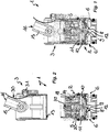
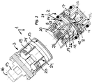
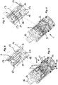
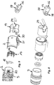
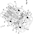
- a shut-off valve 1 is shown in the FIGS. 1 to 10 .
- the shut-off valve 1 has a valve housing which can be inserted into a fluid line.
- the shut-off valve 1 is designed for a sanitary fitting designed as a hand shower holding device and not shown here.
- the shut-off valve 1 is to be used with its trained as Einsetzpatrone valve housing in a guided through the hand shower holder water pipe.
- the valve housing of the shut-off valve 1 has two housing parts 2, 3, which are connectable to each other.
- the shut-off valve 1 is one leading to a hand shower Liquid outlet connected upstream in the flow direction.
- the shut-off valve 1 has a flow opening 7, which delimits a valve seat 8, which is closed by a valve closure 9 in the closed position of the shut-off valve 1 shown here.
- This valve closure 9 is here held movably on the inner circumference of the first housing part 2 via an elastic, membrane-like disk 10.
- a liquid channel 4 is provided which connects the first valve side facing the flow opening 7 with a chamber 11 arranged on the second valve side facing away from the flow opening 7.
- an actuating slide 5 cooperates, which is longitudinally displaceably guided in the valve housing in the housing longitudinal direction.
- the valve housing of the shut-off valve 1 has two housing parts 2, 3, which are connectable to each other.
- the valve seat 8 delimiting flow opening 7, the valve closure 9 and the actuating slide 5 is arranged, while in the second housing part 3, an actuating mechanism is provided which a force exerted on an actuating arm rotary, linear or - as here - Swivel movement in a linear motion on the actuating slide 5 converts.
- the actuating mechanism in the second housing part 3 and the actuating slide 5 in the first housing part 2 are here magnetically coupled to each other in drive connection.
- the actuating slide 5 releases an outlet opening 12 which connects the chamber 11 to the valve outlet 6 of the shut-off valve in a sliding position of the actuating slide 5 which is advanced against a return spring 36 in the guide pin 20 in the direction away from the valve closure 9.
- the portion of the first valve side bounded by the valve seat 8 in the closed position of the shut-off valve 1 is smaller in comparison to the second valve side facing the chamber 11, such that the shut-off valve 1 remains in its closed position solely by the pressure conditions on the two sides of the valve closure 9, as long as the actuating slide 5 closes the outlet opening 12.
- first and the second housing part 2, 3 in their mutually facing partial areas can be inserted into one another and connected to one another.
- a preferably circumferential locking element 13 for example a latching projection provided, which cooperates with a arranged on the outer circumference of the first housing part 2, preferably also circumferential counter-latching means 14, in particular a latching recess cooperates.
- the provided in the second housing part 3 actuating mechanism sets a longitudinal, rotary or - as here - a pivoting movement on the here formed as a pivot arm 15 actuating arm in a linear movement of the actuation mechanism in driving connection with the actuating slide 5 to.
- a pivoting movement of the actuating arm provided on the input side of the actuating mechanism is converted into a linear movement of the actuating slide 5 provided on the output side of the actuating mechanism.
- serving as the actuating arm pivot arm 15 is pivotally mounted in the second housing part 3, at its free, over the valve housing protruding arm end 16 a here not shown hand shower holder for receiving a hand shower can be fastened.
- the second arm end of the pivot arm 15 is brought into drive connection with the actuating slide 5.
- the actuating slide 5 on the one hand and the pivot arm 15 serving as the actuating arm on the other hand are magnetic here coupled together.
- a magnetic carrier 17 is slidably guided in the first housing part, which carries an annular permanent magnet 18.
- the provided in the first housing part 2 magnetic carrier 17 is connected to a coupling piece 19, which is guided in the second housing part 3 slidably.
- the actuating slide 5 is displaceably guided in the first housing part 2 in a guide pin 20 which projects beyond a dividing wall 21.
- the outer peripheral side held on the inner housing circumference partition 21 and integrally connected with her guide pin 20 separates the chamber 11 liquid-tight from the provided in the second housing part 3 actuating mechanism.
- the permanent magnet 18 held on the magnet carrier 17 cooperates with an actuating slide 5 which is ferromagnetic for this purpose, at least in the partial area encompassed by the permanent magnet 18.
- the actuating slide 5 carries in its encompassed by the permanent magnet 18 ferromagnetic portion of a sliding sleeve 22, which favors the relative displacement of the actuating slide 5 and permanent magnet 18 in addition.
- the permanent magnet 18 is annular and the guide pin 20 passes through the ring opening of the permanent magnet 18.
- the coupling piece 19 is simultaneously locked to the magnetic carrier 17.
- On the coupling piece 19 to the front side protruding support arms 23 are provided, which engage behind with their located at the arm ends locking lugs 24 an annular shoulder 25 on the magnetic carrier 17.
- the permanent magnet 18 can be used up to an insertion stop 26 in the here sleeve-shaped magnetic carrier 17, wherein in the sleeve interior of the magnetic carrier 17 at least one locking cam 27 protrudes, which engages behind the permanent magnet 18 resting on the insertion stop 26.
- a pivoting movement of the pivot arm 15, which is triggered in particular by placing a hand shower in the connected to the pivot arm 15 Handbrausehalter is implemented by means of a conversion mechanism in a sliding movement of the coupling piece 19.
- arcuately curved toothings 28 are provided, each combing with an associated counter toothing 29 on the coupling piece 19.
- the pivot arm 15 is pivotable from the open position of the check valve 4 against a restoring force in its closed position.
- the restoring force is designed as at least one return spring 30.
- This return spring 30 is formed here by a resilient and the pivot arm 15 acting on the return tab. In this case, the restoring force exerted by the return tongue 30 is adjustable by means of a set screw 31, with the contact pressure of the return tab 30 can be changed and fixed to the pivot arm 15.
- the shut-off valve 1 can be easily adapted to other sanitary fittings in which, for example, a rotary or linear movement exerted on the actuating arm of the actuating mechanism can be converted into a linear movement of the actuating slide 5.
- At least one valve inlet 32 is provided on the inflow-side end face of the shut-off valve 1.
- the fluid flowing in through the fluid line flows through the at least one valve inlet 32 into the interior of the shut-off valve 1.
- the fluid can flow through the liquid channel 4 into the chamber 11 of the shut-off valve 1 when the flow opening 7 is closed in the closed position shown here. Because of the Chamber 11 facing the valve side compared to the flow opening 7 facing valve side is greater, the valve closure 9 is pressed by the fluid pressure against the valve seat 8 and the valve closure 9 remains securely in the closed position.
- valve outlet 6 opens into a circumferential groove 33 which is provided on the housing periphery of the valve housing.
- two annular seals 34, 35 are provided at the housing periphery of the valve housing, between which the valve outlet 6 is arranged. These ring seals 34, 35 seal the annular gap between the housing outer circumference of the valve housing on the one hand and the inner circumference of the fluid line on the other.
- the fluid line has a downstream line section which is connected between the ring seals 34, 35 with the valve outlet 6 of the shut-off valve 1.
Landscapes
- Engineering & Computer Science (AREA)
- General Engineering & Computer Science (AREA)
- Mechanical Engineering (AREA)
- Mechanically-Actuated Valves (AREA)
- Preventing Unauthorised Actuation Of Valves (AREA)
Claims (18)
- Soupape d'arrêt (1) avec un corps de soupape insérable dans une conduite de fluide, une ouverture de passage (7) prévue dans le corps de soupape, qui entoure un siège de soupape (8) qui dans une position de fermeture de la soupape d'arrêt (1) est fermé par une fermeture de soupape (9), et un coulisseau d'actionnement (5) guidé de façon coulissante en direction longitudinale du corps dans le corps de soupape, qui est en liaison d'entraînement avec un mécanisme d'actionnement, qui convertit un mouvement exercé au niveau d'un bras d'actionnement en un mouvement linéaire au niveau du coulisseau d'actionnement (5), dans laquelle le corps de soupape comporte au moins deux parties de corps (2, 3) pouvant être assemblées l'une à l'autre, dans laquelle l'ouverture de passage (7) entourant le siège de soupape (8), la fermeture de soupape (9) ainsi que le coulisseau d'actionnement (5) sont prévus dans la première partie de corps (2), dans laquelle le mécanisme d'actionnement avec le bras d'actionnement (15) est disposé dans la deuxième partie de corps (3), dans laquelle le mécanisme d'actionnement et le coulisseau d'actionnement (5) sont en liaison d'entraînement l'un avec l'autre par couplage magnétique, dans laquelle le coulisseau d'actionnement (5) est guidé de façon coulissante dans un tourillon de guidage (20), qui est saillant sur une paroi de séparation (21), dans laquelle la paroi de séparation (21) maintenue sur le côté périphérique extérieur sur la périphérie intérieure du corps de la première partie de corps (2) et le tourillon de guidage (20) assemblé à celle-là sépare la région de la première partie de corps (2) contenant la fermeture de soupape (9), le siège de soupape (8) et le coulisseau d'actionnement (5) de façon étanche au liquide de la deuxième partie de corps (3), dans laquelle un support d'aimant (17), qui porte au moins un aimant permanent (18), est guidé de façon coulissante sur le tourillon de guidage (20) et dans laquelle le support d'aimant (17) peut être assemblé à une pièce de couplage (19) qui est guidée de façon coulissante dans la deuxième partie de corps, caractérisée en ce que le mécanisme d'actionnement convertit un mouvement pivotant exercé au niveau du bras d'actionnement (15) en un mouvement linéaire au niveau du coulisseau d'actionnement (5) et la pièce de couplage (19) et le support d'aimant (17) se verrouillent l'un à l'autre lors de l'assemblage de la première et de la deuxième parties de corps (2, 3).
- Soupape d'arrêt selon la revendication 1, caractérisée en ce qu'il est prévu un premier canal de liquide (4), qui relie un premier côté de soupape tourné vers l'ouverture de passage (7) à une chambre (11) disposée sur le deuxième côté de soupape détourné de l'ouverture de passage (7), en ce que le coulisseau d'actionnement (5) libère, dans une position de coulissement du coulisseau d'actionnement (5) avancée dans une direction détournée de la fermeture de soupape (9), au moins une ouverture de sortie (12) dans la fermeture de soupape (9), cette ouverture de sortie (12) reliant la chambre (11) à la sortie de soupape (6), et en ce que la région partielle du premier côté de soupape délimitée par le siège de soupape (8) en position de fermeture de la soupape d'arrêt (1) est plus petite par comparaison avec le deuxième côté de soupape tourné vers la chambre (11).
- Soupape d'arrêt selon la revendication 1 ou 2, caractérisée en ce que la première et la deuxième parties de corps (2, 3) sont insérables l'une dans l'autre par leurs régions partielles tournées l'une vers l'autre et peuvent être assemblées l'une à l'autre de façon séparable.
- Soupape d'arrêt selon la revendication 3, caractérisée en ce que la première et la deuxième parties de corps (2, 3) peuvent être verrouillées l'une à l'autre.
- Soupape d'arrêt selon l'une quelconque des revendications 1 à 4, caractérisée en ce que le bras d'actionnement est réalisé sous la forme d'un bras pivotant (15) monté de façon pivotante dans la deuxième partie de corps, lequel peut être amené en liaison d'entraînement avec le coulisseau d'actionnement (5) dans la première partie de corps (2) lors de l'assemblage des parties de corps (2, 3).
- Soupape d'arrêt selon la revendication 5, caractérisée en ce que le bras d'actionnement réalisé en forme de bras pivotant (15) peut être assemblé à sa première extrémité de bras (16) à un support de douche, de préférence de façon séparable et est en liaison d'entraînement par sa deuxième extrémité de bras avec le coulisseau d'actionnement (5).
- Soupape d'arrêt selon l'une quelconque des revendications 1 à 6, caractérisée en ce que ledit au moins un aimant permanent (18) maintenu sur le support d'aimant (17) coopère avec un coulisseau d'entraînement ferromagnétique (5).
- Soupape d'arrêt selon l'une quelconque des revendications 1 à 7, caractérisée en ce que ledit au moins un aimant permanent (18) maintenu sur le support d'aimant (17) est de forme annulaire et en ce que le tourillon de guidage (20) traverse l'ouverture annulaire dudit au moins un aimant permanent (18).
- Soupape d'arrêt selon la revendication 8, caractérisée en ce que l'aimant permanent de forme annulaire (18) peut être inséré dans le support d'aimant (17) jusqu'à une butée d'insertion (26) et en ce qu'au moins une came d'encliquetage (27) est saillante dans le support d'aimant (17), laquelle s'accroche derrière l'aimant permanent (18) appliqué sur la butée d'insertion (26).
- Soupape d'arrêt selon l'une quelconque des revendications 5 à 9, caractérisée en ce qu'il est prévu un mécanisme de conversion ou un engrenage de conversion, qui convertit un mouvement pivotant du bras d'actionnement réalisé sous forme de bras pivotant (15) en un mouvement coulissant de la pièce de couplage (19).
- Soupape d'arrêt selon l'une quelconque des revendications 5 à 10, caractérisée en ce qu'il est prévu sur le bras pivotant (15) au moins une denture (28) incurvée en forme d'arc de cercle, qui engrène avec une denture opposée (29) qui lui est associée sur la pièce de couplage (19).
- Soupape d'arrêt selon l'une quelconque des revendications 5 à 11, caractérisée en ce que le bras pivotant (15) peut pivoter de la position d'ouverture de la soupape d'arrêt (4) à la position de fermeture de celle-là contre une force de rappel.
- Soupape d'arrêt selon la revendication 12, caractérisée en ce que la force de rappel est produite par au moins un ressort de rappel.
- Soupape d'arrêt selon la revendication 13, caractérisée en ce que le ressort de rappel est formé par une lamelle de rappel (30) élastique et agissant sur le bras pivotant (15).
- Soupape d'arrêt selon l'une quelconque des revendications 12 à 14, caractérisée en ce que la force de rappel est réglable.
- Soupape d'arrêt selon la revendication 15, caractérisée en ce que la pression d'application de la lamelle de rappel (30) au niveau du bras pivotant (15) peut être modifiée et fixée au moyen d'une vis de réglage (31).
- Utilisation d'une soupape d'arrêt selon l'une quelconque des revendications 1 à 16, caractérisée en ce que la soupape d'arrêt (1) est une soupape d'arrêt destinée au transport de liquide.
- Utilisation d'une soupape d'arrêt selon l'une quelconque des revendications 1 à 16, caractérisée en ce que la soupape d'arrêt peut être insérée avec son corps de soupape dans une robinetterie sanitaire réalisée en forme de dispositif de support de douche et y est montée, dans la direction d'écoulement, avant une sortie de liquide (6) conduisant à une douche.
Applications Claiming Priority (2)
| Application Number | Priority Date | Filing Date | Title |
|---|---|---|---|
| DE202014007070.9U DE202014007070U1 (de) | 2014-09-04 | 2014-09-04 | Absperrventil |
| PCT/EP2015/001330 WO2016034257A1 (fr) | 2014-09-04 | 2015-07-01 | Soupape d'arrêt |
Publications (2)
| Publication Number | Publication Date |
|---|---|
| EP3189257A1 EP3189257A1 (fr) | 2017-07-12 |
| EP3189257B1 true EP3189257B1 (fr) | 2018-07-25 |
Family
ID=53524720
Family Applications (1)
| Application Number | Title | Priority Date | Filing Date |
|---|---|---|---|
| EP15734574.5A Not-in-force EP3189257B1 (fr) | 2014-09-04 | 2015-07-01 | Soupape d'arrêt et utilisation d'une telle soupape d'arrêt |
Country Status (5)
| Country | Link |
|---|---|
| EP (1) | EP3189257B1 (fr) |
| CN (3) | CN204704452U (fr) |
| BR (1) | BR112017002556B1 (fr) |
| DE (1) | DE202014007070U1 (fr) |
| WO (1) | WO2016034257A1 (fr) |
Families Citing this family (6)
| Publication number | Priority date | Publication date | Assignee | Title |
|---|---|---|---|---|
| DE202014007070U1 (de) * | 2014-09-04 | 2015-12-08 | Neoperl Gmbh | Absperrventil |
| DE202016001106U1 (de) | 2016-02-22 | 2017-05-23 | Neoperl Gmbh | Ventilbetätigungsvorrichtung |
| DE202016003402U1 (de) * | 2016-05-28 | 2017-08-30 | Neoperl Gmbh | Sanitäre Einsetzeinheit |
| DE102016012472A1 (de) * | 2016-10-19 | 2018-04-19 | Borgwarner Inc. | Ventil und hydraulische Betätigungsvorrichtung mit einem solchen Ventil |
| DE102018200086B3 (de) * | 2018-01-04 | 2018-12-27 | Hansgrohe Se | Schaltvorrichtung und sanitäres Absperrventil |
| DE102019129059A1 (de) * | 2019-10-28 | 2021-04-29 | Grohe Ag | Ventil für eine Sanitärarmatur mit einem Membranventil und einem einstellbaren Steuerstab |
Family Cites Families (13)
| Publication number | Priority date | Publication date | Assignee | Title |
|---|---|---|---|---|
| CN2278131Y (zh) * | 1996-08-07 | 1998-04-08 | 黄太生 | 手动永磁水阀 |
| CN2349422Y (zh) * | 1998-04-08 | 1999-11-17 | 程礼贤 | 磁控单向阀 |
| AT411186B (de) * | 1999-04-07 | 2003-10-27 | Weber Guenter | Einschraubventil |
| DE202004006163U1 (de) * | 2004-04-19 | 2005-09-08 | Interelektrik Ges.M.B.H. & Co. Kg | Dusch-Armatur |
| DE102008004789A1 (de) * | 2008-01-17 | 2009-07-30 | Danfoss A/S | Ventil, insbesondere Schaltventil |
| CN201897000U (zh) * | 2010-08-04 | 2011-07-13 | 富泰和精密制造(深圳)有限公司 | 电动控制水力操作式温度感应阀门 |
| EP2687763B1 (fr) * | 2011-03-17 | 2018-04-25 | T & D Corporation | Système de soupape |
| KR101270515B1 (ko) * | 2011-08-04 | 2013-07-04 | 우성전기공업 주식회사 | 전자석 급수밸브 |
| US9080685B2 (en) * | 2012-02-07 | 2015-07-14 | Tianbaili new technology development Co. Ltd | Double-switched automatic sprinkler valve |
| CN202683382U (zh) * | 2012-03-31 | 2013-01-23 | 开平格林卫浴实业有限公司 | 一种设置截止阀的手持花洒 |
| DE202013002280U1 (de) * | 2013-03-11 | 2014-06-12 | Neoperl Gmbh | Handbrause-Halteeinrichtung |
| CN203162320U (zh) * | 2013-03-29 | 2013-08-28 | 珠海爱迪生节能科技有限公司 | 一种防烫的花洒截止阀 |
| DE202014007070U1 (de) * | 2014-09-04 | 2015-12-08 | Neoperl Gmbh | Absperrventil |
-
2014
- 2014-09-04 DE DE202014007070.9U patent/DE202014007070U1/de not_active Expired - Lifetime
-
2015
- 2015-05-28 CN CN201520353898.0U patent/CN204704452U/zh not_active Expired - Fee Related
- 2015-05-28 CN CN201510279708.XA patent/CN106195386B/zh not_active Expired - Fee Related
- 2015-07-01 BR BR112017002556-6A patent/BR112017002556B1/pt not_active IP Right Cessation
- 2015-07-01 EP EP15734574.5A patent/EP3189257B1/fr not_active Not-in-force
- 2015-07-01 CN CN201580046803.3A patent/CN106795977B/zh not_active Expired - Fee Related
- 2015-07-01 WO PCT/EP2015/001330 patent/WO2016034257A1/fr not_active Ceased
Non-Patent Citations (1)
| Title |
|---|
| None * |
Also Published As
| Publication number | Publication date |
|---|---|
| CN204704452U (zh) | 2015-10-14 |
| EP3189257A1 (fr) | 2017-07-12 |
| CN106195386A (zh) | 2016-12-07 |
| DE202014007070U1 (de) | 2015-12-08 |
| CN106795977A (zh) | 2017-05-31 |
| WO2016034257A1 (fr) | 2016-03-10 |
| CN106795977B (zh) | 2019-04-05 |
| BR112017002556A2 (pt) | 2017-12-05 |
| BR112017002556B1 (pt) | 2022-06-21 |
| CN106195386B (zh) | 2019-07-26 |
Similar Documents
| Publication | Publication Date | Title |
|---|---|---|
| EP2971387B1 (fr) | Dispositif support de douchette | |
| DE69408058T2 (de) | Umstellventilkartusche | |
| EP2909383B1 (fr) | Faucet avec une pomme de douche | |
| EP3189257A1 (fr) | Soupape d'arrêt | |
| WO2008009390A1 (fr) | Embout de sortie | |
| EP4295064B1 (fr) | Soupape sanitaire | |
| DE102014113386A1 (de) | Ventilkartusche für eine Sanitärarmatur | |
| EP3080505A1 (fr) | Raccord de tuyau souple | |
| DE202021100839U1 (de) | Sanitärventil | |
| EP3728747A1 (fr) | Soupape d'évacuation pour une chasse d'eau sanitaire | |
| EP3572592B1 (fr) | Dispositif de sortie de fluide pourvu de tuyau télescopique de sortie | |
| EP1061299A2 (fr) | Soupape d'inverseur | |
| EP1794377B1 (fr) | Armature sanitaire encastree | |
| DE60215545T2 (de) | Brauseschlauch mit einem zweiwegeventil und zweiwegenventil für brauseschlauch | |
| DE102012019358A1 (de) | Sanitäre Auslaufarmatur mit einer Handbrause | |
| DE102014012876A1 (de) | Absperrventil | |
| DE19542748B4 (de) | Umschaltventil | |
| DE102021104007A1 (de) | Sanitärventil | |
| DE2616898C3 (de) | Steuervorrichtung für Mischventile | |
| DE4141172B4 (de) | Vorrichtung zum Umstellen eines Ventilgliedes an einer Sanitärarmatur | |
| EP1855036B1 (fr) | Insert d'une soupape pour un robinet extérieur protégé contre le gel et robinet extérieur protégé contre le gel | |
| DE3939224A1 (de) | Sanitaere mischarmatur | |
| DE102006033410B4 (de) | Auslaufmundstück | |
| DE102013004074B4 (de) | Handbrause-Halteeinrichtung | |
| DE102021104009A1 (de) | Sanitärventil |
Legal Events
| Date | Code | Title | Description |
|---|---|---|---|
| STAA | Information on the status of an ep patent application or granted ep patent |
Free format text: STATUS: THE INTERNATIONAL PUBLICATION HAS BEEN MADE |
|
| PUAI | Public reference made under article 153(3) epc to a published international application that has entered the european phase |
Free format text: ORIGINAL CODE: 0009012 |
|
| STAA | Information on the status of an ep patent application or granted ep patent |
Free format text: STATUS: REQUEST FOR EXAMINATION WAS MADE |
|
| 17P | Request for examination filed |
Effective date: 20170404 |
|
| AK | Designated contracting states |
Kind code of ref document: A1 Designated state(s): AL AT BE BG CH CY CZ DE DK EE ES FI FR GB GR HR HU IE IS IT LI LT LU LV MC MK MT NL NO PL PT RO RS SE SI SK SM TR |
|
| AX | Request for extension of the european patent |
Extension state: BA ME |
|
| DAV | Request for validation of the european patent (deleted) | ||
| DAX | Request for extension of the european patent (deleted) | ||
| GRAP | Despatch of communication of intention to grant a patent |
Free format text: ORIGINAL CODE: EPIDOSNIGR1 |
|
| STAA | Information on the status of an ep patent application or granted ep patent |
Free format text: STATUS: GRANT OF PATENT IS INTENDED |
|
| INTG | Intention to grant announced |
Effective date: 20180411 |
|
| GRAS | Grant fee paid |
Free format text: ORIGINAL CODE: EPIDOSNIGR3 |
|
| GRAA | (expected) grant |
Free format text: ORIGINAL CODE: 0009210 |
|
| STAA | Information on the status of an ep patent application or granted ep patent |
Free format text: STATUS: THE PATENT HAS BEEN GRANTED |
|
| AK | Designated contracting states |
Kind code of ref document: B1 Designated state(s): AL AT BE BG CH CY CZ DE DK EE ES FI FR GB GR HR HU IE IS IT LI LT LU LV MC MK MT NL NO PL PT RO RS SE SI SK SM TR |
|
| REG | Reference to a national code |
Ref country code: GB Ref legal event code: FG4D Free format text: NOT ENGLISH |
|
| REG | Reference to a national code |
Ref country code: CH Ref legal event code: EP |
|
| REG | Reference to a national code |
Ref country code: AT Ref legal event code: REF Ref document number: 1022130 Country of ref document: AT Kind code of ref document: T Effective date: 20180815 |
|
| REG | Reference to a national code |
Ref country code: IE Ref legal event code: FG4D Free format text: LANGUAGE OF EP DOCUMENT: GERMAN |
|
| REG | Reference to a national code |
Ref country code: DE Ref legal event code: R096 Ref document number: 502015005234 Country of ref document: DE |
|
| REG | Reference to a national code |
Ref country code: NL Ref legal event code: MP Effective date: 20180725 |
|
| REG | Reference to a national code |
Ref country code: LT Ref legal event code: MG4D |
|
| PG25 | Lapsed in a contracting state [announced via postgrant information from national office to epo] |
Ref country code: NL Free format text: LAPSE BECAUSE OF FAILURE TO SUBMIT A TRANSLATION OF THE DESCRIPTION OR TO PAY THE FEE WITHIN THE PRESCRIBED TIME-LIMIT Effective date: 20180725 |
|
| PG25 | Lapsed in a contracting state [announced via postgrant information from national office to epo] |
Ref country code: PL Free format text: LAPSE BECAUSE OF FAILURE TO SUBMIT A TRANSLATION OF THE DESCRIPTION OR TO PAY THE FEE WITHIN THE PRESCRIBED TIME-LIMIT Effective date: 20180725 Ref country code: IS Free format text: LAPSE BECAUSE OF FAILURE TO SUBMIT A TRANSLATION OF THE DESCRIPTION OR TO PAY THE FEE WITHIN THE PRESCRIBED TIME-LIMIT Effective date: 20181125 Ref country code: SE Free format text: LAPSE BECAUSE OF FAILURE TO SUBMIT A TRANSLATION OF THE DESCRIPTION OR TO PAY THE FEE WITHIN THE PRESCRIBED TIME-LIMIT Effective date: 20180725 Ref country code: NO Free format text: LAPSE BECAUSE OF FAILURE TO SUBMIT A TRANSLATION OF THE DESCRIPTION OR TO PAY THE FEE WITHIN THE PRESCRIBED TIME-LIMIT Effective date: 20181025 Ref country code: RS Free format text: LAPSE BECAUSE OF FAILURE TO SUBMIT A TRANSLATION OF THE DESCRIPTION OR TO PAY THE FEE WITHIN THE PRESCRIBED TIME-LIMIT Effective date: 20180725 Ref country code: FI Free format text: LAPSE BECAUSE OF FAILURE TO SUBMIT A TRANSLATION OF THE DESCRIPTION OR TO PAY THE FEE WITHIN THE PRESCRIBED TIME-LIMIT Effective date: 20180725 Ref country code: GR Free format text: LAPSE BECAUSE OF FAILURE TO SUBMIT A TRANSLATION OF THE DESCRIPTION OR TO PAY THE FEE WITHIN THE PRESCRIBED TIME-LIMIT Effective date: 20181026 Ref country code: BG Free format text: LAPSE BECAUSE OF FAILURE TO SUBMIT A TRANSLATION OF THE DESCRIPTION OR TO PAY THE FEE WITHIN THE PRESCRIBED TIME-LIMIT Effective date: 20181025 Ref country code: LT Free format text: LAPSE BECAUSE OF FAILURE TO SUBMIT A TRANSLATION OF THE DESCRIPTION OR TO PAY THE FEE WITHIN THE PRESCRIBED TIME-LIMIT Effective date: 20180725 |
|
| PG25 | Lapsed in a contracting state [announced via postgrant information from national office to epo] |
Ref country code: HR Free format text: LAPSE BECAUSE OF FAILURE TO SUBMIT A TRANSLATION OF THE DESCRIPTION OR TO PAY THE FEE WITHIN THE PRESCRIBED TIME-LIMIT Effective date: 20180725 Ref country code: AL Free format text: LAPSE BECAUSE OF FAILURE TO SUBMIT A TRANSLATION OF THE DESCRIPTION OR TO PAY THE FEE WITHIN THE PRESCRIBED TIME-LIMIT Effective date: 20180725 Ref country code: LV Free format text: LAPSE BECAUSE OF FAILURE TO SUBMIT A TRANSLATION OF THE DESCRIPTION OR TO PAY THE FEE WITHIN THE PRESCRIBED TIME-LIMIT Effective date: 20180725 |
|
| REG | Reference to a national code |
Ref country code: DE Ref legal event code: R097 Ref document number: 502015005234 Country of ref document: DE |
|
| PG25 | Lapsed in a contracting state [announced via postgrant information from national office to epo] |
Ref country code: CZ Free format text: LAPSE BECAUSE OF FAILURE TO SUBMIT A TRANSLATION OF THE DESCRIPTION OR TO PAY THE FEE WITHIN THE PRESCRIBED TIME-LIMIT Effective date: 20180725 Ref country code: RO Free format text: LAPSE BECAUSE OF FAILURE TO SUBMIT A TRANSLATION OF THE DESCRIPTION OR TO PAY THE FEE WITHIN THE PRESCRIBED TIME-LIMIT Effective date: 20180725 Ref country code: ES Free format text: LAPSE BECAUSE OF FAILURE TO SUBMIT A TRANSLATION OF THE DESCRIPTION OR TO PAY THE FEE WITHIN THE PRESCRIBED TIME-LIMIT Effective date: 20180725 Ref country code: EE Free format text: LAPSE BECAUSE OF FAILURE TO SUBMIT A TRANSLATION OF THE DESCRIPTION OR TO PAY THE FEE WITHIN THE PRESCRIBED TIME-LIMIT Effective date: 20180725 |
|
| PG25 | Lapsed in a contracting state [announced via postgrant information from national office to epo] |
Ref country code: DK Free format text: LAPSE BECAUSE OF FAILURE TO SUBMIT A TRANSLATION OF THE DESCRIPTION OR TO PAY THE FEE WITHIN THE PRESCRIBED TIME-LIMIT Effective date: 20180725 Ref country code: SM Free format text: LAPSE BECAUSE OF FAILURE TO SUBMIT A TRANSLATION OF THE DESCRIPTION OR TO PAY THE FEE WITHIN THE PRESCRIBED TIME-LIMIT Effective date: 20180725 Ref country code: SK Free format text: LAPSE BECAUSE OF FAILURE TO SUBMIT A TRANSLATION OF THE DESCRIPTION OR TO PAY THE FEE WITHIN THE PRESCRIBED TIME-LIMIT Effective date: 20180725 |
|
| PLBE | No opposition filed within time limit |
Free format text: ORIGINAL CODE: 0009261 |
|
| STAA | Information on the status of an ep patent application or granted ep patent |
Free format text: STATUS: NO OPPOSITION FILED WITHIN TIME LIMIT |
|
| 26N | No opposition filed |
Effective date: 20190426 |
|
| PG25 | Lapsed in a contracting state [announced via postgrant information from national office to epo] |
Ref country code: SI Free format text: LAPSE BECAUSE OF FAILURE TO SUBMIT A TRANSLATION OF THE DESCRIPTION OR TO PAY THE FEE WITHIN THE PRESCRIBED TIME-LIMIT Effective date: 20180725 |
|
| PG25 | Lapsed in a contracting state [announced via postgrant information from national office to epo] |
Ref country code: MC Free format text: LAPSE BECAUSE OF FAILURE TO SUBMIT A TRANSLATION OF THE DESCRIPTION OR TO PAY THE FEE WITHIN THE PRESCRIBED TIME-LIMIT Effective date: 20180725 |
|
| REG | Reference to a national code |
Ref country code: CH Ref legal event code: PL |
|
| GBPC | Gb: european patent ceased through non-payment of renewal fee |
Effective date: 20190701 |
|
| REG | Reference to a national code |
Ref country code: BE Ref legal event code: MM Effective date: 20190731 |
|
| PG25 | Lapsed in a contracting state [announced via postgrant information from national office to epo] |
Ref country code: GB Free format text: LAPSE BECAUSE OF NON-PAYMENT OF DUE FEES Effective date: 20190701 |
|
| PG25 | Lapsed in a contracting state [announced via postgrant information from national office to epo] |
Ref country code: BE Free format text: LAPSE BECAUSE OF NON-PAYMENT OF DUE FEES Effective date: 20190731 Ref country code: LU Free format text: LAPSE BECAUSE OF NON-PAYMENT OF DUE FEES Effective date: 20190701 Ref country code: LI Free format text: LAPSE BECAUSE OF NON-PAYMENT OF DUE FEES Effective date: 20190731 Ref country code: CH Free format text: LAPSE BECAUSE OF NON-PAYMENT OF DUE FEES Effective date: 20190731 |
|
| PG25 | Lapsed in a contracting state [announced via postgrant information from national office to epo] |
Ref country code: FR Free format text: LAPSE BECAUSE OF NON-PAYMENT OF DUE FEES Effective date: 20190731 Ref country code: PT Free format text: LAPSE BECAUSE OF FAILURE TO SUBMIT A TRANSLATION OF THE DESCRIPTION OR TO PAY THE FEE WITHIN THE PRESCRIBED TIME-LIMIT Effective date: 20181125 |
|
| PG25 | Lapsed in a contracting state [announced via postgrant information from national office to epo] |
Ref country code: IE Free format text: LAPSE BECAUSE OF NON-PAYMENT OF DUE FEES Effective date: 20190701 |
|
| PG25 | Lapsed in a contracting state [announced via postgrant information from national office to epo] |
Ref country code: CY Free format text: LAPSE BECAUSE OF FAILURE TO SUBMIT A TRANSLATION OF THE DESCRIPTION OR TO PAY THE FEE WITHIN THE PRESCRIBED TIME-LIMIT Effective date: 20180725 |
|
| PG25 | Lapsed in a contracting state [announced via postgrant information from national office to epo] |
Ref country code: HU Free format text: LAPSE BECAUSE OF FAILURE TO SUBMIT A TRANSLATION OF THE DESCRIPTION OR TO PAY THE FEE WITHIN THE PRESCRIBED TIME-LIMIT; INVALID AB INITIO Effective date: 20150701 Ref country code: MT Free format text: LAPSE BECAUSE OF FAILURE TO SUBMIT A TRANSLATION OF THE DESCRIPTION OR TO PAY THE FEE WITHIN THE PRESCRIBED TIME-LIMIT Effective date: 20180725 |
|
| REG | Reference to a national code |
Ref country code: AT Ref legal event code: MM01 Ref document number: 1022130 Country of ref document: AT Kind code of ref document: T Effective date: 20200701 |
|
| PG25 | Lapsed in a contracting state [announced via postgrant information from national office to epo] |
Ref country code: AT Free format text: LAPSE BECAUSE OF NON-PAYMENT OF DUE FEES Effective date: 20200701 |
|
| PG25 | Lapsed in a contracting state [announced via postgrant information from national office to epo] |
Ref country code: MK Free format text: LAPSE BECAUSE OF FAILURE TO SUBMIT A TRANSLATION OF THE DESCRIPTION OR TO PAY THE FEE WITHIN THE PRESCRIBED TIME-LIMIT Effective date: 20180725 |
|
| PGFP | Annual fee paid to national office [announced via postgrant information from national office to epo] |
Ref country code: TR Payment date: 20220624 Year of fee payment: 8 |
|
| PGFP | Annual fee paid to national office [announced via postgrant information from national office to epo] |
Ref country code: DE Payment date: 20220822 Year of fee payment: 8 Ref country code: IT Payment date: 20220729 Year of fee payment: 8 |
|
| REG | Reference to a national code |
Ref country code: DE Ref legal event code: R119 Ref document number: 502015005234 Country of ref document: DE |
|
| PG25 | Lapsed in a contracting state [announced via postgrant information from national office to epo] |
Ref country code: DE Free format text: LAPSE BECAUSE OF NON-PAYMENT OF DUE FEES Effective date: 20240201 |
|
| PG25 | Lapsed in a contracting state [announced via postgrant information from national office to epo] |
Ref country code: IT Free format text: LAPSE BECAUSE OF NON-PAYMENT OF DUE FEES Effective date: 20230701 |
|
| PG25 | Lapsed in a contracting state [announced via postgrant information from national office to epo] |
Ref country code: TR Free format text: LAPSE BECAUSE OF NON-PAYMENT OF DUE FEES Effective date: 20230701 |