EP3189294B1 - Système de stockage d'énergie de réfrigération ou thermique par des matériaux à changement de phase - Google Patents
Système de stockage d'énergie de réfrigération ou thermique par des matériaux à changement de phase Download PDFInfo
- Publication number
- EP3189294B1 EP3189294B1 EP15791774.1A EP15791774A EP3189294B1 EP 3189294 B1 EP3189294 B1 EP 3189294B1 EP 15791774 A EP15791774 A EP 15791774A EP 3189294 B1 EP3189294 B1 EP 3189294B1
- Authority
- EP
- European Patent Office
- Prior art keywords
- fluid
- heat exchanger
- secondary fluid
- refrigeration
- frigories
- Prior art date
- Legal status (The legal status is an assumption and is not a legal conclusion. Google has not performed a legal analysis and makes no representation as to the accuracy of the status listed.)
- Active
Links
- 239000012782 phase change material Substances 0.000 title claims description 83
- 238000005057 refrigeration Methods 0.000 title claims description 55
- 238000004146 energy storage Methods 0.000 title claims description 21
- 239000012530 fluid Substances 0.000 claims description 198
- 238000003860 storage Methods 0.000 claims description 53
- 238000000926 separation method Methods 0.000 claims description 12
- 238000009826 distribution Methods 0.000 claims description 8
- 238000007711 solidification Methods 0.000 claims description 8
- 230000008023 solidification Effects 0.000 claims description 8
- XLYOFNOQVPJJNP-UHFFFAOYSA-N water Substances O XLYOFNOQVPJJNP-UHFFFAOYSA-N 0.000 claims description 8
- 239000012528 membrane Substances 0.000 claims description 3
- 239000012071 phase Substances 0.000 description 21
- 239000000463 material Substances 0.000 description 13
- 239000007788 liquid Substances 0.000 description 7
- 239000007787 solid Substances 0.000 description 6
- 230000010354 integration Effects 0.000 description 5
- 239000013078 crystal Substances 0.000 description 4
- 230000015572 biosynthetic process Effects 0.000 description 3
- 230000008859 change Effects 0.000 description 3
- 230000009467 reduction Effects 0.000 description 3
- LYCAIKOWRPUZTN-UHFFFAOYSA-N Ethylene glycol Chemical compound OCCO LYCAIKOWRPUZTN-UHFFFAOYSA-N 0.000 description 2
- 239000002775 capsule Substances 0.000 description 2
- 238000010586 diagram Methods 0.000 description 2
- 238000007599 discharging Methods 0.000 description 2
- 238000005516 engineering process Methods 0.000 description 2
- 230000004927 fusion Effects 0.000 description 2
- 238000010438 heat treatment Methods 0.000 description 2
- 239000005457 ice water Substances 0.000 description 2
- 238000000034 method Methods 0.000 description 2
- 239000002245 particle Substances 0.000 description 2
- 230000008569 process Effects 0.000 description 2
- 239000002002 slurry Substances 0.000 description 2
- 239000007790 solid phase Substances 0.000 description 2
- 238000004781 supercooling Methods 0.000 description 2
- 230000007704 transition Effects 0.000 description 2
- 238000009827 uniform distribution Methods 0.000 description 2
- 240000008100 Brassica rapa Species 0.000 description 1
- 241000196324 Embryophyta Species 0.000 description 1
- 238000004378 air conditioning Methods 0.000 description 1
- 239000000956 alloy Substances 0.000 description 1
- 229910045601 alloy Inorganic materials 0.000 description 1
- 238000000576 coating method Methods 0.000 description 1
- 239000002131 composite material Substances 0.000 description 1
- 230000003750 conditioning effect Effects 0.000 description 1
- 239000006185 dispersion Substances 0.000 description 1
- 238000006073 displacement reaction Methods 0.000 description 1
- 230000000694 effects Effects 0.000 description 1
- 239000006023 eutectic alloy Substances 0.000 description 1
- 238000005338 heat storage Methods 0.000 description 1
- WGCNASOHLSPBMP-UHFFFAOYSA-N hydroxyacetaldehyde Natural products OCC=O WGCNASOHLSPBMP-UHFFFAOYSA-N 0.000 description 1
- 239000011810 insulating material Substances 0.000 description 1
- 238000004519 manufacturing process Methods 0.000 description 1
- 239000003094 microcapsule Substances 0.000 description 1
- 239000000203 mixture Substances 0.000 description 1
- 238000012986 modification Methods 0.000 description 1
- 230000004048 modification Effects 0.000 description 1
- 238000012856 packing Methods 0.000 description 1
- 239000012188 paraffin wax Substances 0.000 description 1
- 230000000750 progressive effect Effects 0.000 description 1
- 238000010926 purge Methods 0.000 description 1
- 230000001988 toxicity Effects 0.000 description 1
- 231100000419 toxicity Toxicity 0.000 description 1
- 238000002604 ultrasonography Methods 0.000 description 1
Images


Classifications
-
- F—MECHANICAL ENGINEERING; LIGHTING; HEATING; WEAPONS; BLASTING
- F28—HEAT EXCHANGE IN GENERAL
- F28D—HEAT-EXCHANGE APPARATUS, NOT PROVIDED FOR IN ANOTHER SUBCLASS, IN WHICH THE HEAT-EXCHANGE MEDIA DO NOT COME INTO DIRECT CONTACT
- F28D20/00—Heat storage plants or apparatus in general; Regenerative heat-exchange apparatus not covered by groups F28D17/00 or F28D19/00
- F28D20/02—Heat storage plants or apparatus in general; Regenerative heat-exchange apparatus not covered by groups F28D17/00 or F28D19/00 using latent heat
- F28D20/025—Heat storage plants or apparatus in general; Regenerative heat-exchange apparatus not covered by groups F28D17/00 or F28D19/00 using latent heat the latent heat storage material being in direct contact with a heat-exchange medium or with another heat storage material
-
- F—MECHANICAL ENGINEERING; LIGHTING; HEATING; WEAPONS; BLASTING
- F24—HEATING; RANGES; VENTILATING
- F24F—AIR-CONDITIONING; AIR-HUMIDIFICATION; VENTILATION; USE OF AIR CURRENTS FOR SCREENING
- F24F5/00—Air-conditioning systems or apparatus not covered by F24F1/00 or F24F3/00, e.g. using solar heat or combined with household units such as an oven or water heater
- F24F5/0007—Air-conditioning systems or apparatus not covered by F24F1/00 or F24F3/00, e.g. using solar heat or combined with household units such as an oven or water heater cooling apparatus specially adapted for use in air-conditioning
- F24F5/0017—Air-conditioning systems or apparatus not covered by F24F1/00 or F24F3/00, e.g. using solar heat or combined with household units such as an oven or water heater cooling apparatus specially adapted for use in air-conditioning using cold storage bodies, e.g. ice
- F24F5/0021—Air-conditioning systems or apparatus not covered by F24F1/00 or F24F3/00, e.g. using solar heat or combined with household units such as an oven or water heater cooling apparatus specially adapted for use in air-conditioning using cold storage bodies, e.g. ice using phase change material [PCM] for storage
-
- F—MECHANICAL ENGINEERING; LIGHTING; HEATING; WEAPONS; BLASTING
- F25—REFRIGERATION OR COOLING; COMBINED HEATING AND REFRIGERATION SYSTEMS; HEAT PUMP SYSTEMS; MANUFACTURE OR STORAGE OF ICE; LIQUEFACTION SOLIDIFICATION OF GASES
- F25B—REFRIGERATION MACHINES, PLANTS OR SYSTEMS; COMBINED HEATING AND REFRIGERATION SYSTEMS; HEAT PUMP SYSTEMS
- F25B25/00—Machines, plants or systems, using a combination of modes of operation covered by two or more of the groups F25B1/00 - F25B23/00
- F25B25/005—Machines, plants or systems, using a combination of modes of operation covered by two or more of the groups F25B1/00 - F25B23/00 using primary and secondary systems
-
- F—MECHANICAL ENGINEERING; LIGHTING; HEATING; WEAPONS; BLASTING
- F28—HEAT EXCHANGE IN GENERAL
- F28C—HEAT-EXCHANGE APPARATUS, NOT PROVIDED FOR IN ANOTHER SUBCLASS, IN WHICH THE HEAT-EXCHANGE MEDIA COME INTO DIRECT CONTACT WITHOUT CHEMICAL INTERACTION
- F28C1/00—Direct-contact trickle coolers, e.g. cooling towers
- F28C1/14—Direct-contact trickle coolers, e.g. cooling towers comprising also a non-direct contact heat exchange
-
- F—MECHANICAL ENGINEERING; LIGHTING; HEATING; WEAPONS; BLASTING
- F28—HEAT EXCHANGE IN GENERAL
- F28D—HEAT-EXCHANGE APPARATUS, NOT PROVIDED FOR IN ANOTHER SUBCLASS, IN WHICH THE HEAT-EXCHANGE MEDIA DO NOT COME INTO DIRECT CONTACT
- F28D1/00—Heat-exchange apparatus having stationary conduit assemblies for one heat-exchange medium only, the media being in contact with different sides of the conduit wall, in which the other heat-exchange medium is a large body of fluid, e.g. domestic or motor car radiators
- F28D1/02—Heat-exchange apparatus having stationary conduit assemblies for one heat-exchange medium only, the media being in contact with different sides of the conduit wall, in which the other heat-exchange medium is a large body of fluid, e.g. domestic or motor car radiators with heat-exchange conduits immersed in the body of fluid
- F28D1/04—Heat-exchange apparatus having stationary conduit assemblies for one heat-exchange medium only, the media being in contact with different sides of the conduit wall, in which the other heat-exchange medium is a large body of fluid, e.g. domestic or motor car radiators with heat-exchange conduits immersed in the body of fluid with tubular conduits
- F28D1/0408—Multi-circuit heat exchangers, e.g. integrating different heat exchange sections in the same unit or heat exchangers for more than two fluids
- F28D1/0426—Multi-circuit heat exchangers, e.g. integrating different heat exchange sections in the same unit or heat exchangers for more than two fluids with units having particular arrangement relative to the large body of fluid, e.g. with interleaved units or with adjacent heat exchange units in common air flow or with units extending at an angle to each other or with units arranged around a central element
-
- F—MECHANICAL ENGINEERING; LIGHTING; HEATING; WEAPONS; BLASTING
- F28—HEAT EXCHANGE IN GENERAL
- F28D—HEAT-EXCHANGE APPARATUS, NOT PROVIDED FOR IN ANOTHER SUBCLASS, IN WHICH THE HEAT-EXCHANGE MEDIA DO NOT COME INTO DIRECT CONTACT
- F28D1/00—Heat-exchange apparatus having stationary conduit assemblies for one heat-exchange medium only, the media being in contact with different sides of the conduit wall, in which the other heat-exchange medium is a large body of fluid, e.g. domestic or motor car radiators
- F28D1/02—Heat-exchange apparatus having stationary conduit assemblies for one heat-exchange medium only, the media being in contact with different sides of the conduit wall, in which the other heat-exchange medium is a large body of fluid, e.g. domestic or motor car radiators with heat-exchange conduits immersed in the body of fluid
- F28D1/04—Heat-exchange apparatus having stationary conduit assemblies for one heat-exchange medium only, the media being in contact with different sides of the conduit wall, in which the other heat-exchange medium is a large body of fluid, e.g. domestic or motor car radiators with heat-exchange conduits immersed in the body of fluid with tubular conduits
- F28D1/047—Heat-exchange apparatus having stationary conduit assemblies for one heat-exchange medium only, the media being in contact with different sides of the conduit wall, in which the other heat-exchange medium is a large body of fluid, e.g. domestic or motor car radiators with heat-exchange conduits immersed in the body of fluid with tubular conduits the conduits being bent, e.g. in a serpentine or zig-zag
- F28D1/0472—Heat-exchange apparatus having stationary conduit assemblies for one heat-exchange medium only, the media being in contact with different sides of the conduit wall, in which the other heat-exchange medium is a large body of fluid, e.g. domestic or motor car radiators with heat-exchange conduits immersed in the body of fluid with tubular conduits the conduits being bent, e.g. in a serpentine or zig-zag the conduits being helically or spirally coiled
-
- F—MECHANICAL ENGINEERING; LIGHTING; HEATING; WEAPONS; BLASTING
- F28—HEAT EXCHANGE IN GENERAL
- F28D—HEAT-EXCHANGE APPARATUS, NOT PROVIDED FOR IN ANOTHER SUBCLASS, IN WHICH THE HEAT-EXCHANGE MEDIA DO NOT COME INTO DIRECT CONTACT
- F28D20/00—Heat storage plants or apparatus in general; Regenerative heat-exchange apparatus not covered by groups F28D17/00 or F28D19/00
- F28D20/02—Heat storage plants or apparatus in general; Regenerative heat-exchange apparatus not covered by groups F28D17/00 or F28D19/00 using latent heat
- F28D20/021—Heat storage plants or apparatus in general; Regenerative heat-exchange apparatus not covered by groups F28D17/00 or F28D19/00 using latent heat the latent heat storage material and the heat-exchanging means being enclosed in one container
-
- F—MECHANICAL ENGINEERING; LIGHTING; HEATING; WEAPONS; BLASTING
- F28—HEAT EXCHANGE IN GENERAL
- F28D—HEAT-EXCHANGE APPARATUS, NOT PROVIDED FOR IN ANOTHER SUBCLASS, IN WHICH THE HEAT-EXCHANGE MEDIA DO NOT COME INTO DIRECT CONTACT
- F28D20/00—Heat storage plants or apparatus in general; Regenerative heat-exchange apparatus not covered by groups F28D17/00 or F28D19/00
- F28D20/02—Heat storage plants or apparatus in general; Regenerative heat-exchange apparatus not covered by groups F28D17/00 or F28D19/00 using latent heat
- F28D20/028—Control arrangements therefor
-
- F—MECHANICAL ENGINEERING; LIGHTING; HEATING; WEAPONS; BLASTING
- F28—HEAT EXCHANGE IN GENERAL
- F28D—HEAT-EXCHANGE APPARATUS, NOT PROVIDED FOR IN ANOTHER SUBCLASS, IN WHICH THE HEAT-EXCHANGE MEDIA DO NOT COME INTO DIRECT CONTACT
- F28D7/00—Heat-exchange apparatus having stationary tubular conduit assemblies for both heat-exchange media, the media being in contact with different sides of a conduit wall
- F28D7/10—Heat-exchange apparatus having stationary tubular conduit assemblies for both heat-exchange media, the media being in contact with different sides of a conduit wall the conduits being arranged one within the other, e.g. concentrically
- F28D7/14—Heat-exchange apparatus having stationary tubular conduit assemblies for both heat-exchange media, the media being in contact with different sides of a conduit wall the conduits being arranged one within the other, e.g. concentrically both tubes being bent
-
- F—MECHANICAL ENGINEERING; LIGHTING; HEATING; WEAPONS; BLASTING
- F28—HEAT EXCHANGE IN GENERAL
- F28F—DETAILS OF HEAT-EXCHANGE AND HEAT-TRANSFER APPARATUS, OF GENERAL APPLICATION
- F28F19/00—Preventing the formation of deposits or corrosion, e.g. by using filters or scrapers
- F28F19/02—Preventing the formation of deposits or corrosion, e.g. by using filters or scrapers by using coatings, e.g. vitreous or enamel coatings
-
- F—MECHANICAL ENGINEERING; LIGHTING; HEATING; WEAPONS; BLASTING
- F28—HEAT EXCHANGE IN GENERAL
- F28F—DETAILS OF HEAT-EXCHANGE AND HEAT-TRANSFER APPARATUS, OF GENERAL APPLICATION
- F28F25/00—Component parts of trickle coolers
- F28F25/02—Component parts of trickle coolers for distributing, circulating, and accumulating liquid
-
- F—MECHANICAL ENGINEERING; LIGHTING; HEATING; WEAPONS; BLASTING
- F28—HEAT EXCHANGE IN GENERAL
- F28F—DETAILS OF HEAT-EXCHANGE AND HEAT-TRANSFER APPARATUS, OF GENERAL APPLICATION
- F28F25/00—Component parts of trickle coolers
- F28F25/02—Component parts of trickle coolers for distributing, circulating, and accumulating liquid
- F28F25/06—Spray nozzles or spray pipes
-
- F—MECHANICAL ENGINEERING; LIGHTING; HEATING; WEAPONS; BLASTING
- F28—HEAT EXCHANGE IN GENERAL
- F28F—DETAILS OF HEAT-EXCHANGE AND HEAT-TRANSFER APPARATUS, OF GENERAL APPLICATION
- F28F27/00—Control arrangements or safety devices specially adapted for heat-exchange or heat-transfer apparatus
- F28F27/02—Control arrangements or safety devices specially adapted for heat-exchange or heat-transfer apparatus for controlling the distribution of heat-exchange media between different channels
-
- F—MECHANICAL ENGINEERING; LIGHTING; HEATING; WEAPONS; BLASTING
- F28—HEAT EXCHANGE IN GENERAL
- F28F—DETAILS OF HEAT-EXCHANGE AND HEAT-TRANSFER APPARATUS, OF GENERAL APPLICATION
- F28F9/00—Casings; Header boxes; Auxiliary supports for elements; Auxiliary members within casings
- F28F9/007—Auxiliary supports for elements
- F28F9/013—Auxiliary supports for elements for tubes or tube-assemblies
- F28F9/0132—Auxiliary supports for elements for tubes or tube-assemblies formed by slats, tie-rods, articulated or expandable rods
-
- F—MECHANICAL ENGINEERING; LIGHTING; HEATING; WEAPONS; BLASTING
- F28—HEAT EXCHANGE IN GENERAL
- F28D—HEAT-EXCHANGE APPARATUS, NOT PROVIDED FOR IN ANOTHER SUBCLASS, IN WHICH THE HEAT-EXCHANGE MEDIA DO NOT COME INTO DIRECT CONTACT
- F28D20/00—Heat storage plants or apparatus in general; Regenerative heat-exchange apparatus not covered by groups F28D17/00 or F28D19/00
- F28D2020/0065—Details, e.g. particular heat storage tanks, auxiliary members within tanks
- F28D2020/0069—Distributing arrangements; Fluid deflecting means
-
- Y—GENERAL TAGGING OF NEW TECHNOLOGICAL DEVELOPMENTS; GENERAL TAGGING OF CROSS-SECTIONAL TECHNOLOGIES SPANNING OVER SEVERAL SECTIONS OF THE IPC; TECHNICAL SUBJECTS COVERED BY FORMER USPC CROSS-REFERENCE ART COLLECTIONS [XRACs] AND DIGESTS
- Y02—TECHNOLOGIES OR APPLICATIONS FOR MITIGATION OR ADAPTATION AGAINST CLIMATE CHANGE
- Y02E—REDUCTION OF GREENHOUSE GAS [GHG] EMISSIONS, RELATED TO ENERGY GENERATION, TRANSMISSION OR DISTRIBUTION
- Y02E60/00—Enabling technologies; Technologies with a potential or indirect contribution to GHG emissions mitigation
- Y02E60/14—Thermal energy storage
Definitions
- the present invention relates to a storage system of refrigeration or thermal energy through the use of phase change materials (PCM), in particular for air conditioning or heating of domestic, working, shopping, etc. environments.
- PCM phase change materials
- the invention relates to a system that allows to maximize the transfer of refrigeration or thermal energy between a material of the PCM type and a refrigeration or heating fluid both during storage and release phases of energy from tank storage system, thus increasing the potential applications of cold or heat storage systems, and to optimize the period of withdrawal of energy from the supply main or of use of self-produced energy.
- PCM phase change materials
- PCS thanks to the dispersion of droplets or micro-capsules of PCM-type material within a liquid carrier, allow improving the kinetics of energy transfer between the refrigerating PCM type material and liquid carrier and ensuring an additional storage component constituted by the sensible heat of the continuous phase.
- PCS have application problems due to the high viscosity of the fluid to be handled and the reduced energy density storage.
- a refrigeration or thermal energy storage system for storing refrigeration or thermal energy to be released when required by users, comprising a body, closed and insulated, said body being configured to contain two fluids within its volume, respectively a Phase Change Material (PCM) type fluid and a secondary fluid, said two fluids being immiscible each other and having different density, so as to be stratified within the volume of said body; withdrawal means configured to draw said secondary fluid from said body, and to convey the same inside a heat exchanger, said heat exchanger being configured to exchange frigories, or calories, with said secondary fluid; and distribution means configured to draw said secondary fluid from said heat exchanger, and to distribute, within said body, said secondary fluid into said PCM type fluid, so as that said secondary fluid exchanges with said PCM type fluid frigories, or calories, absorbed in said heat exchanger, said secondary fluid having a solidification temperature substantially lower than that of said PCM type fluid, said heat exchanger being housed inside said body, and being exchange frigories, or calories, between said secondary fluid
- PCM Phase Change Material
- said withdrawal means are placed at least partially in the upper, or lower, part of said body, depending on the density value of said secondary fluid, and in that said distribution means are placed at least partially in the upper, or lower, part of said body, in an opposite manner to the position of said withdrawal means.
- said volume of said body comprises separation means to prevent the inlet of said PCM type fluid into said withdrawal means.
- said separation means comprise a grid, or a membrane, impermeable to said PCM type fluid and placed so as that only said secondary fluid is substantially present in correspondence of said withdrawal means.
- said separation means comprise an "S" path to prevent the inlet of said PCM type fluid into said withdrawal means.
- said withdrawal means comprises a pump to convey said secondary fluid into said heat exchanger.
- said distribution means comprise shower nozzles and/or nebulizers and/or hydraulic vortexes to distribute, inside said body, said secondary fluid into said PCM type fluid.
- said secondary fluid is present within said body with a percentage in volume preferably between 5% and 50%.
- said secondary fluid has a density greater than that of said PCM type fluid.
- said secondary fluid is water.
- a storage plant to store refrigeration or thermal energy to be released when required comprising a refrigeration or thermal energy storage system as described in the above; a refrigeration or thermal unit connected to said heat exchanger, and configured to release frigories or calories to a primary fluid when said system is in a refrigeration or thermal energy storage configuration, so as that said frigories, or calories are later released by said primary fluid to said secondary fluid in said heat exchanger, and further later exchanged between said secondary fluid and said PCM type fluid inside said body; users, connected to said heat exchanger so as that, when said system is in a energy release configuration, said PCM type fluid exchanges frigories, or calories, with said secondary fluid inside said body, and later said secondary fluid releases said frigories, or calories, to said primary fluid in said heat exchanger, and further later said primary fluid releases said frigories, or calories, to said users; and a valves and pumps system for the circulation of said primary fluid so as that said system can pass from a refrigeration or thermal energy storage configuration to a energy release configuration, and vice vers
- said refrigeration or thermal unit is connected to said heat exchanger and to said users, so as that, said refrigeration or thermal unit exchanges frigories or calories with said primary fluid, and later said primary fluid exchanges frigories or calories with said secondary fluid in said heat exchanger and with said users, and in that said valves and pumps system allows to operate in a refrigeration, or thermal, energy storage mode releasing frigories or calories to said secondary fluid in said heat exchanger or to said users or to both of them at the same time, and in a refrigeration or thermal energy release mode with release of frigories or calories to said primary fluid by said secondary fluid in said heat exchanger or by part of said refrigeration or thermal unit or by both of them at the same time.
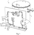
- Said storage system 1 comprises a tank 2 for storage of refrigeration energy, a secondary circuit 3 and a system of showers or nebulizers 4, contained within the volume of the tank 2.
- Said tank 2 can be any insulated, closed, body of appropriate size to kWh to be stored and configured to contain within its volume a PCM type fluid and a secondary fluid, immiscible each other and having different density.
- said body is preferably cylindrical.
- Physical characteristics of said fluids determine the layering of the same within the volume of the storage tank 2, with the consequent possibility of withdrawing the secondary fluid, depending on the density value of the latter, from the top or the bottom of tank 2.
- said PCM type fluid has a solidification temperature preferably equal to 5°C, while said secondary fluid, present within said tank 2 with a volume rate preferably between 5% and 50%, has a solidification temperature lower than that of said PCM type fluid.
- Said secondary circuit 3 comprises a pump 5 for displacement of secondary fluid from inside the tank 2 towards a heat exchanger 6 and from this to the system showers or nebulizers 4.
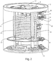
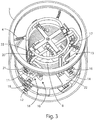
- Said heat exchanger 6 is preferably comprised of a system of double concentric tubes circular coils and is housed within said tank 2 and immersed within the PCM type fluid volume.
- said coil system is comprised by two identical coils connected together to operate in parallel.
- Secondary fluid circulates within inner tube 7 of said heat exchanger 6, while a primary fluid circulates in counter current within the outer tube 8, entering and exiting in and from a refrigeration system (not shown in these figures) by means of a primary circuit 9. it is evident that the two fluids may also circulate in co-current.
- Said inner tube 7 of said heat exchanger 6 is connected, through a system of pipes 10, to a pipe union 11, the latter being connected, through the secondary circuit 3, to a pipe union 12 of the tank 2; said means 12, 3, 11 and 10 allow the flow of the secondary fluid from the storage tank 2 to the heat exchanger 6.
- Said inner tube 7 is also connected, through a system of pipes 13, to a pipe union 14, the latter being connected, by means of a circuit 15, to a pipe union 16, connected, through a system of pipes 17, to the showers or nebulizers system 4; said means 13, 14, 15, 16 and 17 allow the flow of the secondary fluid from heat exchanger 6 to the showers or nebulizers system 4.
- Said outer pipe 8 is connected, through a system of pipes 18, to a pipe union 19, and, through a system of pipes 20, to a pipe union 21, connected to said pipe union 19 through the primary circuit 9; said means 9, 18, 19, 21 and 20 allow the flow of the primary fluid in, and from, the heat exchanger 6.
- the showers or nebulizers system 4 is present in the upper part of the storage tank 2, for uniform distribution on the surface, and then in the PCM type fluid volume, of droplets of secondary fluid coming from the heat exchanger 6.
- Separation means 22 are housed within the volume of the tank 2, to prevent the release of the type PCM fluid in the secondary circuit 3.
- said separation means comprise a grid, disposed in such a way that only said secondary fluid is substantially present in correspondence with the nozzle 12.
- Said heat exchanger 6, said showers or nebulizers system 4 and said separation means 22 are supported by a beam system 23.
- Operation of the storage system 1 provides for the withdrawal of the secondary fluid from the bottom of the tank 2 and the circulation of said fluid, thanks to the pump 5, within the secondary circuit 3, in the heat exchanger 6 and in the circuit 15, until reaching the system showers or nebulizers system 4.
- Secondary fluid absorbs frigories within the heat exchanger 6, during the storage of refrigerating energy within tank 2, and releases frigories during the release phase of refrigerating energy of tank 2, from, and to, the primary fluid circulating within said heat exchanger heat 6.
- Primary fluid is cooled by a refrigeration system during the storage of refrigeration energy within tank 2, while during the release phase of refrigerating energy from tank 2, before being sent to a final user, it is cooled by the current of the secondary fluid.
- Secondary fluid coming from heat exchanger 6, is introduced within the tank 2 through the showers or nebulizers system 4, which ensures a uniform distribution of the droplets of the secondary fluid in the PCM type fluid volume.
- the droplets of secondary fluid evenly run down along the PCM type fluid head optimally transferring refrigeration energy from secondary fluid to the PCM type fluid during the storage of refrigerating energy in tank 2 and by the PCM type fluid to the secondary fluid during the release phase of refrigerating energy from tank 2, so as to obtain, respectively, the solidification of the liquid PCM type fluid and the fusion of the solid PCM type fluid.
- Solidification of PCM type fluid during the storage of refrigerating energy in tank 2 thus permits storage, in storage tank 2, of refrigerating energy which is then released during the release phase of refrigerating energy from tank 2, through the fusion of the solid PCM type fluid.
- showers or nebulizers system by generating droplets of secondary fluid that evenly run down the PCM type fluid head, allows increasing the contact surface for heat exchange and, due to viscous forces, ensures handling the type PCM fluid, improving energy transportation coefficients.
- the type PCM fluid confined within the tank, it is prevented a movement of the type PCM fluid, under phase change conditions, especially during energy storage, that could generate operational problems such as blockage of pipelines or rupture the pumps. Furthermore, the reduced time of energy storage and release from storage tank allow the use of the storage system according to the present invention to optimize the energy withdrawal period from the main supply or of use of self-produced energy.
- Another embodiment of the present invention provides the application of coatings on the inner surface of the pipes in which circulates the secondary fluid, avoiding the adhesion of the solid PCM type fluid.
- the storage tank 2 can have cubic shape, conical shape, frustum-conical shape, parallelepiped shape, etc. and/or composite shape obtained by the union of one or more of the mentioned above shapes.
- a further embodiment of the present invention involves the use of ultrasound systems, or similar systems, in order to facilitate the formation of first PCM type fluid crystals during the storage of refrigeration energy by tank 2 and thus reduce the eventual supercooling effect of PCM type fluid.
- Another embodiment of the present invention involves the use of only the PCM type fluids and of the primary fluid, thereby avoiding the use of a secondary circuit.
- it is the primary fluid which, descending through the PCM type fluid head, releases, during the storage phase, and absorbs, during the release phase, the refrigerating energy.
- the heat exchanger 6 may be located outside the storage tank 2, in order to increase the PCM type fluid volume the that can be contained within the tank 2, and/or different technologies may be used compared to the double concentric pipes coils system, such as rube bundle exchanger, plate exchangers, horizontal or vertical exchangers, shirt exchangers.
- Another embodiment of the present invention provides the use of separation means different from the grid, such as a selective membrane to only the secondary fluid, placed on the surface or within the secondary fluid volume.
- the suction duct 25 provides a vertical extension 26, protected by a conduit 27 coaxial thereto and of greater diameter, closed from the upper side and with a possible valve 28 which, if necessary, allows purging by suction.
- Said optional device can be usefully employed in the case in which density of the liquid PCM type fluid is less than that of the secondary fluid while the density of PCM type solid PCM type fluid is higher than that of said secondary fluid.
- separation devices 22 may permit the passage of solid particles of small diameter of PCM type fluid. The presence of said devices 24 can ensure an additional level of separation, avoiding that the particles of solid PCM type fluid deposited on the bottom occlude the suction duct 25.
- Another embodiment of the present invention provides the use of movable, continuous and discrete showers or nebulizers systems.
- FIG 6 there is shown a first embodiment of a circuit 29 for the integration of the cold storage system 1 according to the present invention with a refrigerator group 30 and a user 31, arranged functionally in parallel each other.
- Said circuit 29 comprises a three-way diverting valve 32, in a 0% or 100% mode, a three-way mixing valve 33, a pump 34 for moving the primary fluid through the circuit valve 29 and a three-way diverting valve 35.
- circuit 29 will be made with reference to a heat exchanger 6 in which the primary fluid and the secondary fluid circulate in counter current, but it should be understood that the elements distinguishing the circuit does not vary if the two fluids circulate in co-current.
- Said valve 32 allows, during the storage of refrigerating energy, the flow of the primary fluid, cooled by the refrigerator group 30, in the heat exchanger 6, while, during the release phase of refrigerating energy, allows the flow of the primary fluid, cooled by the secondary fluid circulating in the heat exchanger 6, towards the user 31.
- the mixing valve 33 allows the mixing of the primary fluid coming from the heat exchanger 6 with the primary fluid coming 31 from the user, by sending the mixed fluids to the intake of pump 34 and then in the refrigerator group 30. If, instead, during the storage of refrigerating energy it is provided only the transfer of refrigeration from the cooled primary fluid to the secondary fluid, said mixing valve 33 allows only the circulation of the primary fluid coming from the heat exchanger 6 to the intake of pump 34 and then in the refrigerator group 30.
- said valve 33 allows only the circulation of the primary fluid coming from the user 31 to the intake of the pump 34.
- Said diverting valve 35 enables, during the storage of refrigerating energy, the flow of the primary fluid leaving the heat exchanger 6 through the valve 33 and then through the pump 34, toward the refrigeration group 30, while, during the phase of release of refrigerating energy, allows the flow of the primary fluid coming from the user 31 through the valve 33, and then through the pump 34, toward the refrigeration group 30 and/or to the heat exchanger 6.
- the operation of the circuit 29 according to the present invention provides that, during the storage of refrigerating energy, the primary fluid cooled by the refrigeration group 30 can refrigerate the secondary fluid circulating in the heat exchanger 6 and/or provide the refrigeration power required by the user 31.
- the refrigerating power required by the user 31 can be provided by the primary fluid cooled by the refrigeration unit 30 and/or the primary fluid cooled by the secondary fluid circulating in the heat exchanger 6.
- the integration proposed according to the present invention of the cold storage system with a refrigeration system and a user allows to optimize the withdrawal period of the energy from the mains, reducing load peaks (peak shaving), or the use of self-produced energy.
- frigories, or part of frigories, required by the user during the peak hours may be supplied from the cold storage tank, previously loaded during the non-peak time period, with a consequent reduction of the peak power and increase the refrigerating machines COP.
- the presence of the cold storage tank in the circuit 29, operating to support the refrigerating machine allows to reduce the power of the latter, with a consequent reduction of production costs, and of the price, of the refrigerating machine.
- a suitable management system of the energy flows it is possible to operate the refrigerating machine at constant, or nearly constant, power, and at the optimum operation point (greater COP), by providing the peaks of refrigeration energy required by the user to the storage system.
- FIG. 7 there is shown a second embodiment of the circuit 29 for the integration of the cold storage system 1 according to the present invention with a refrigeration group 30 and a user 31, functionally arranged both in parallel and in series.
- Said circuit 29 comprises two pumps 36, 37 and six two-way valves 38, 39, 40, 41, 42 and 43.
- valves 39 and 42 and opened valves 43 and 40 an operation of energy release in parallel is obtained, which can be managed by modulating the opening of valves 38 and 41.
Landscapes
- Engineering & Computer Science (AREA)
- Mechanical Engineering (AREA)
- General Engineering & Computer Science (AREA)
- Physics & Mathematics (AREA)
- Thermal Sciences (AREA)
- Life Sciences & Earth Sciences (AREA)
- Sustainable Development (AREA)
- Chemical & Material Sciences (AREA)
- Combustion & Propulsion (AREA)
- Other Air-Conditioning Systems (AREA)
- Devices That Are Associated With Refrigeration Equipment (AREA)
Claims (12)
- Système de stockage d'énergie de réfrigération ou thermique (1) destiné à stocker de l'énergie de réfrigération ou thermique devant être libérée lorsqu'elle est requise par des utilisateurs, comprenant
un corps (2), fermé et isolé, ledit corps (2) étant conçu pour contenir deux fluides à l'intérieur de son volume, respectivement un fluide de type matériau à changement de phase (PCM) et un fluide secondaire, lesdits deux fluides étant immiscibles l'un par rapport à l'autre et possédant une densité différente, afin d'être stratifiés à l'intérieur du volume dudit corps (2) ;
des moyens de retrait (3) conçus pour aspirer ledit fluide secondaire à partir dudit corps (2), et pour le transporter à l'intérieur d'un échangeur thermique (6), ledit échangeur thermique (6) étant configuré pour échanger des frigories, ou des calories, avec ledit fluide secondaire ; et
des moyens de distribution (4) conçus pour aspirer ledit fluide secondaire à partir dudit échangeur thermique (6), et pour distribuer, à l'intérieur dudit corps (2), ledit fluide secondaire dans ledit fluide de type PCM, afin que ledit fluide secondaire échange, avec ledit fluide de type PCM, des calories, ou des frigories, absorbées dans ledit échangeur thermique (6),
ledit fluide secondaire possédant une température de solidification sensiblement inférieure à celle dudit fluide de type PCM,
ledit échangeur thermique (6) comprenant un premier tuyau (7), raccordé au niveau de ses extrémités respectivement auxdits moyens de retrait (3) et auxdits moyens de distribution (4), pour la circulation dudit fluide secondaire,
ledit système de stockage d'énergie (1) étant caractérisé en ce que
ledit échangeur thermique (6) est logé à l'intérieur dudit corps (2), et échange des frigories, ou des calories, entre ledit fluide secondaire et un fluide primaire,
et en ce qu'un second tuyau (8), concentrique par rapport audit premier tuyau, est conçu pour être raccordé à un circuit (9) externe audit corps (2), pour la circulation dudit fluide primaire. - Système (1) selon la revendication précédente, caractérisé en ce que lesdits moyens de retrait (3) sont placés au moins partiellement dans la partie supérieure, ou inférieure, dudit corps (2), en fonction de la valeur de densité dudit fluide secondaire, et en ce que lesdits moyens de distribution (4) sont placés au moins partiellement dans la partie supérieure, ou inférieure, dudit corps (2), d'une manière opposée à la position desdits moyens de retrait (3).
- Système (1) selon l'une des revendications précédentes, caractérisé en ce que ledit volume dudit corps (2) comprend des moyens de séparation (22) pour empêcher l'entrée dudit fluide de type PCM dans lesdits moyens de retrait (3).
- Système (1) selon la revendication 3, caractérisé en ce que lesdits moyens de séparation (22) comprennent une grille, ou une membrane, imperméable audit fluide de type PCM et placée de sorte que seul ledit fluide secondaire est sensiblement présent en correspondance desdits moyens de retrait (3).
- Système (1) selon la revendication 3, caractérisé en ce que lesdits moyens de séparation comprennent un trajet en « S » pour empêcher l'entrée dudit fluide de type PCM dans lesdits moyens de retrait (3).
- Système (1) selon l'une des revendications précédentes, caractérisé en ce que lesdits moyens de retrait (3) comprennent une pompe (5) pour acheminer ledit fluide secondaire dans ledit échangeur thermique (6).
- Système (1) selon l'une des revendications précédentes, caractérisé en ce que lesdits moyens de distribution (4) comprennent des pommes de douche et/ou des nébuliseurs et/ou des tourbillons hydrauliques pour distribuer, à l'intérieur dudit corps (2), ledit fluide secondaire dans ledit fluide de type PCM.
- Système (1) selon l'une des revendications précédentes, caractérisé en ce que ledit fluide secondaire est présent à l'intérieur dudit corps (2) avec un pourcentage en volume de préférence entre 5 % et 50 %.
- Système (1) selon l'une des revendications précédentes, caractérisé en ce que ledit fluide secondaire possède une densité supérieure à celle dudit fluide de type PCM.
- Système (1) selon l'une des revendications précédentes, caractérisé en ce que ledit fluide secondaire est de l'eau.
- Installation de stockage (29) pour stocker de l'énergie de réfrigération ou thermique devant être libérée lorsqu'elle est nécessaire, comprenant
un système de stockage d'énergie de réfrigération ou thermique (1) selon l'une des revendications 1 à 10 ;
une unité de réfrigération ou thermique (30) raccordée audit échangeur thermique (6), et conçue pour libérer des frigories, ou des calories, vers un fluide primaire lorsque ledit système (29) est dans une configuration de stockage d'énergie de réfrigération ou thermique, de sorte que lesdites frigories, ou calories, sont libérées par la suite par ledit fluide primaire vers ledit fluide secondaire dans ledit échangeur thermique (6), et échangées en outre par la suite entre ledit fluide secondaire et ledit fluide de type PCM à l'intérieur dudit corps (2) ;
des utilisateurs (31), raccordés audit échangeur thermique (6) de sorte que, lorsque ledit système (29) est dans une configuration de libération d'énergie, ledit fluide de type PCM échange des frigories, ou des calories, avec ledit fluide secondaire à l'intérieur dudit corps (2), et par la suite, ledit fluide secondaire libère lesdites frigories, ou calories, vers ledit fluide primaire dans ledit échangeur thermique (6), et par la suite en outre, ledit fluide primaire libère lesdites frigories, ou calories, vers lesdits utilisateurs (31) ; et
un système de soupapes et de pompes pour la circulation dudit fluide primaire de sorte que ledit système (29) peut passer d'une configuration de stockage d'énergie de réfrigération ou thermique à une configuration de libération d'énergie, et vice versa. - Installation de stockage (29) selon la revendication 11, caractérisée en ce que ladite unité de réfrigération ou thermique (30) est raccordée audit échangeur thermique (6) et auxdits utilisateurs (31), de sorte que ladite unité de réfrigération ou thermique (30) échange des frigories, ou des calories, avec ledit fluide primaire, et par la suite, ledit fluide primaire échange des frigories, ou des calories, avec ledit fluide secondaire dans ledit échangeur thermique (6) et avec lesdits utilisateurs (31), et en ce que ledit système de soupapes et de pompes permet de fonctionner dans un mode de stockage d'énergie de réfrigération ou thermique libérant des frigories, ou des calories, vers ledit fluide secondaire dans ledit échangeur thermique (6) ou vers lesdits utilisateurs (31) ou les deux en même temps, et dans un mode de libération d'énergie de réfrigération ou thermique avec libération de frigories, ou de calories, vers ledit fluide primaire par ledit fluide secondaire dans ledit échangeur thermique (6) ou par une partie de ladite unité de réfrigération ou thermique (30) ou par les deux en même temps.
Applications Claiming Priority (2)
| Application Number | Priority Date | Filing Date | Title |
|---|---|---|---|
| ITRM20140500 | 2014-09-04 | ||
| PCT/IT2015/000209 WO2016035105A1 (fr) | 2014-09-04 | 2015-09-02 | Système de stockage d'énergie de réfrigération ou thermique par des matériaux à changement de phase |
Publications (2)
| Publication Number | Publication Date |
|---|---|
| EP3189294A1 EP3189294A1 (fr) | 2017-07-12 |
| EP3189294B1 true EP3189294B1 (fr) | 2020-06-24 |
Family
ID=51799247
Family Applications (1)
| Application Number | Title | Priority Date | Filing Date |
|---|---|---|---|
| EP15791774.1A Active EP3189294B1 (fr) | 2014-09-04 | 2015-09-02 | Système de stockage d'énergie de réfrigération ou thermique par des matériaux à changement de phase |
Country Status (5)
| Country | Link |
|---|---|
| US (1) | US20170248377A1 (fr) |
| EP (1) | EP3189294B1 (fr) |
| CN (1) | CN107110614A (fr) |
| AU (1) | AU2015310472A1 (fr) |
| WO (1) | WO2016035105A1 (fr) |
Families Citing this family (10)
| Publication number | Priority date | Publication date | Assignee | Title |
|---|---|---|---|---|
| JP6720752B2 (ja) * | 2016-07-25 | 2020-07-08 | 富士通株式会社 | 液浸冷却装置、液浸冷却システム、及び液浸冷却装置の制御方法 |
| EP3379191B1 (fr) | 2017-03-20 | 2020-03-11 | Lumenion GmbH | Dispositif d'accumulateur de chaleur et procédé de fonctionnement d'un dispositif d'accumulateur de chaleur |
| JP2021520478A (ja) * | 2018-04-04 | 2021-08-19 | アクティブ エナジー システムズ | 相変化材料を凍結するための熱交換システム及び相変化材料を凍結する方法 |
| WO2020206306A1 (fr) | 2019-04-05 | 2020-10-08 | American Aerogel Corporation | Matériaux à changement de phase non miscibles multiples contenus dans un récipient commun |
| CN111102860B (zh) * | 2020-01-07 | 2025-03-25 | 南京工业大学 | 一种带有涡状盘管的相变储冷装置 |
| CN112728789B (zh) * | 2021-01-19 | 2022-10-21 | 太原理工大学 | 一种相变蓄热换热一体化水箱 |
| CN112944203B (zh) * | 2021-03-22 | 2022-11-01 | 中海石油气电集团有限责任公司 | 一种基于相变保温材料的保温保冷循环系统 |
| US11680754B2 (en) | 2021-04-09 | 2023-06-20 | Trane International Inc. | Systems and methods for thermal storage solid phase formation removal |
| US11970652B1 (en) | 2023-02-16 | 2024-04-30 | Microera Power Inc. | Thermal energy storage with actively tunable phase change materials |
| CN116853508B (zh) * | 2023-09-04 | 2023-11-14 | 中国航空工业集团公司金城南京机电液压工程研究中心 | 一种飞行器喷雾冷却控制方法及装置 |
Family Cites Families (7)
| Publication number | Priority date | Publication date | Assignee | Title |
|---|---|---|---|---|
| US2996894A (en) * | 1956-12-13 | 1961-08-22 | Gen Electric | Method and apparatus for the recovery of latent heat of fusion |
| DE2607168C3 (de) * | 1976-02-21 | 1981-04-09 | Deutsche Forschungs- und Versuchsanstalt für Luft- und Raumfahrt e.V., 5300 Bonn | Vorrichtung zum Austauschen von Wärme |
| US4109702A (en) * | 1976-08-06 | 1978-08-29 | Greene Norman Donald | Energy storage and retrieval as heat |
| CH639477A5 (de) * | 1979-04-18 | 1983-11-15 | Sulzer Ag | Verfahren zum waermeaustausch in einem latentwaermespeicher sowie vorrichtung zur durchfuehrung des verfahrens. |
| US4696338A (en) * | 1982-06-01 | 1987-09-29 | Thermal Energy Stroage, Inc. | Latent heat storage and transfer system and method |
| EP2288856A1 (fr) * | 2007-08-01 | 2011-03-02 | Hydox Pty Ltd | Dispositif de chauffage de fluide |
| CN103291408A (zh) * | 2012-02-27 | 2013-09-11 | 上海索菲玛汽车滤清器有限公司 | 液体润滑剂的分配装置 |
-
2015
- 2015-09-02 CN CN201580056051.9A patent/CN107110614A/zh active Pending
- 2015-09-02 EP EP15791774.1A patent/EP3189294B1/fr active Active
- 2015-09-02 US US15/508,044 patent/US20170248377A1/en not_active Abandoned
- 2015-09-02 WO PCT/IT2015/000209 patent/WO2016035105A1/fr not_active Ceased
- 2015-09-02 AU AU2015310472A patent/AU2015310472A1/en not_active Abandoned
Non-Patent Citations (1)
| Title |
|---|
| None * |
Also Published As
| Publication number | Publication date |
|---|---|
| US20170248377A1 (en) | 2017-08-31 |
| AU2015310472A1 (en) | 2017-04-20 |
| WO2016035105A1 (fr) | 2016-03-10 |
| CN107110614A (zh) | 2017-08-29 |
| EP3189294A1 (fr) | 2017-07-12 |
Similar Documents
| Publication | Publication Date | Title |
|---|---|---|
| EP3189294B1 (fr) | Système de stockage d'énergie de réfrigération ou thermique par des matériaux à changement de phase | |
| US10088243B2 (en) | Thermal energy battery with enhanced heat exchange capability and modularity | |
| US4131158A (en) | Storage arrangement for thermal energy | |
| US7942018B2 (en) | Apparatus for cooling or heating thermal storage using microencapsulated phase change material slurries | |
| JP7477180B2 (ja) | 蓄熱容器内の流体の流れ | |
| US20130105106A1 (en) | Systems And Methods For Thermal Energy Storage | |
| US20110083827A1 (en) | Cooling system with integral thermal energy storage | |
| US9482461B2 (en) | Coolant heat exchanger having a scraper for each heat exchange interface surface | |
| US20110083459A1 (en) | Heat exchanger with integral phase change material for heating and cooling applications | |
| Chen et al. | Experimental investigation on PCM cold storage integrated with ejector cooling system | |
| JP2012180993A (ja) | 潜熱蓄熱貯湯槽及び給湯装置 | |
| JP2008020177A (ja) | 蓄熱システム | |
| CN101846420A (zh) | 制冷设备 | |
| US11519675B1 (en) | Heating system | |
| CN111351165B (zh) | 一种隔间分形蓄冰槽 | |
| CN113933336A (zh) | 相变材料测试组件、测试系统及控制方法 | |
| CN100478635C (zh) | 用于冷却食品的设备 | |
| CN217005463U (zh) | 热管系统及制冷设备 | |
| US6158236A (en) | Refrigeration capacity accumulator | |
| CN201697408U (zh) | 一种制冷设备 | |
| CN105953337B (zh) | 冰蓄热空调机组及其控制方法 | |
| CN206430398U (zh) | 一种热虹吸油冷却系统 | |
| CN200940970Y (zh) | 热管式蓄冰融冰蓄冷装置 | |
| CN112629149B (zh) | 一种用于制冷或加热液体的设备 | |
| CN223896660U (zh) | 相变蓄能装置以及暖通空调装置 |
Legal Events
| Date | Code | Title | Description |
|---|---|---|---|
| STAA | Information on the status of an ep patent application or granted ep patent |
Free format text: STATUS: THE INTERNATIONAL PUBLICATION HAS BEEN MADE |
|
| PUAI | Public reference made under article 153(3) epc to a published international application that has entered the european phase |
Free format text: ORIGINAL CODE: 0009012 |
|
| STAA | Information on the status of an ep patent application or granted ep patent |
Free format text: STATUS: REQUEST FOR EXAMINATION WAS MADE |
|
| 17P | Request for examination filed |
Effective date: 20170330 |
|
| AK | Designated contracting states |
Kind code of ref document: A1 Designated state(s): AL AT BE BG CH CY CZ DE DK EE ES FI FR GB GR HR HU IE IS IT LI LT LU LV MC MK MT NL NO PL PT RO RS SE SI SK SM TR |
|
| AX | Request for extension of the european patent |
Extension state: BA ME |
|
| DAX | Request for extension of the european patent (deleted) | ||
| GRAP | Despatch of communication of intention to grant a patent |
Free format text: ORIGINAL CODE: EPIDOSNIGR1 |
|
| STAA | Information on the status of an ep patent application or granted ep patent |
Free format text: STATUS: GRANT OF PATENT IS INTENDED |
|
| RIC1 | Information provided on ipc code assigned before grant |
Ipc: F28F 9/013 20060101ALI20191212BHEP Ipc: F28D 7/14 20060101ALI20191212BHEP Ipc: F24F 5/00 20060101ALI20191212BHEP Ipc: F28D 1/04 20060101ALI20191212BHEP Ipc: F25B 25/00 20060101ALI20191212BHEP Ipc: F28D 20/02 20060101AFI20191212BHEP |
|
| INTG | Intention to grant announced |
Effective date: 20200113 |
|
| GRAS | Grant fee paid |
Free format text: ORIGINAL CODE: EPIDOSNIGR3 |
|
| GRAA | (expected) grant |
Free format text: ORIGINAL CODE: 0009210 |
|
| STAA | Information on the status of an ep patent application or granted ep patent |
Free format text: STATUS: THE PATENT HAS BEEN GRANTED |
|
| AK | Designated contracting states |
Kind code of ref document: B1 Designated state(s): AL AT BE BG CH CY CZ DE DK EE ES FI FR GB GR HR HU IE IS IT LI LT LU LV MC MK MT NL NO PL PT RO RS SE SI SK SM TR |
|
| REG | Reference to a national code |
Ref country code: GB Ref legal event code: FG4D |
|
| REG | Reference to a national code |
Ref country code: CH Ref legal event code: EP |
|
| REG | Reference to a national code |
Ref country code: AT Ref legal event code: REF Ref document number: 1284308 Country of ref document: AT Kind code of ref document: T Effective date: 20200715 |
|
| REG | Reference to a national code |
Ref country code: DE Ref legal event code: R096 Ref document number: 602015054775 Country of ref document: DE |
|
| REG | Reference to a national code |
Ref country code: IE Ref legal event code: FG4D |
|
| PG25 | Lapsed in a contracting state [announced via postgrant information from national office to epo] |
Ref country code: LT Free format text: LAPSE BECAUSE OF FAILURE TO SUBMIT A TRANSLATION OF THE DESCRIPTION OR TO PAY THE FEE WITHIN THE PRESCRIBED TIME-LIMIT Effective date: 20200624 Ref country code: GR Free format text: LAPSE BECAUSE OF FAILURE TO SUBMIT A TRANSLATION OF THE DESCRIPTION OR TO PAY THE FEE WITHIN THE PRESCRIBED TIME-LIMIT Effective date: 20200925 Ref country code: NO Free format text: LAPSE BECAUSE OF FAILURE TO SUBMIT A TRANSLATION OF THE DESCRIPTION OR TO PAY THE FEE WITHIN THE PRESCRIBED TIME-LIMIT Effective date: 20200924 Ref country code: SE Free format text: LAPSE BECAUSE OF FAILURE TO SUBMIT A TRANSLATION OF THE DESCRIPTION OR TO PAY THE FEE WITHIN THE PRESCRIBED TIME-LIMIT Effective date: 20200624 Ref country code: FI Free format text: LAPSE BECAUSE OF FAILURE TO SUBMIT A TRANSLATION OF THE DESCRIPTION OR TO PAY THE FEE WITHIN THE PRESCRIBED TIME-LIMIT Effective date: 20200624 |
|
| REG | Reference to a national code |
Ref country code: LT Ref legal event code: MG4D |
|
| PG25 | Lapsed in a contracting state [announced via postgrant information from national office to epo] |
Ref country code: HR Free format text: LAPSE BECAUSE OF FAILURE TO SUBMIT A TRANSLATION OF THE DESCRIPTION OR TO PAY THE FEE WITHIN THE PRESCRIBED TIME-LIMIT Effective date: 20200624 Ref country code: RS Free format text: LAPSE BECAUSE OF FAILURE TO SUBMIT A TRANSLATION OF THE DESCRIPTION OR TO PAY THE FEE WITHIN THE PRESCRIBED TIME-LIMIT Effective date: 20200624 Ref country code: LV Free format text: LAPSE BECAUSE OF FAILURE TO SUBMIT A TRANSLATION OF THE DESCRIPTION OR TO PAY THE FEE WITHIN THE PRESCRIBED TIME-LIMIT Effective date: 20200624 Ref country code: BG Free format text: LAPSE BECAUSE OF FAILURE TO SUBMIT A TRANSLATION OF THE DESCRIPTION OR TO PAY THE FEE WITHIN THE PRESCRIBED TIME-LIMIT Effective date: 20200924 |
|
| REG | Reference to a national code |
Ref country code: NL Ref legal event code: MP Effective date: 20200624 |
|
| REG | Reference to a national code |
Ref country code: AT Ref legal event code: MK05 Ref document number: 1284308 Country of ref document: AT Kind code of ref document: T Effective date: 20200624 |
|
| PG25 | Lapsed in a contracting state [announced via postgrant information from national office to epo] |
Ref country code: AL Free format text: LAPSE BECAUSE OF FAILURE TO SUBMIT A TRANSLATION OF THE DESCRIPTION OR TO PAY THE FEE WITHIN THE PRESCRIBED TIME-LIMIT Effective date: 20200624 Ref country code: NL Free format text: LAPSE BECAUSE OF FAILURE TO SUBMIT A TRANSLATION OF THE DESCRIPTION OR TO PAY THE FEE WITHIN THE PRESCRIBED TIME-LIMIT Effective date: 20200624 |
|
| PG25 | Lapsed in a contracting state [announced via postgrant information from national office to epo] |
Ref country code: PT Free format text: LAPSE BECAUSE OF FAILURE TO SUBMIT A TRANSLATION OF THE DESCRIPTION OR TO PAY THE FEE WITHIN THE PRESCRIBED TIME-LIMIT Effective date: 20201026 Ref country code: ES Free format text: LAPSE BECAUSE OF FAILURE TO SUBMIT A TRANSLATION OF THE DESCRIPTION OR TO PAY THE FEE WITHIN THE PRESCRIBED TIME-LIMIT Effective date: 20200624 Ref country code: CZ Free format text: LAPSE BECAUSE OF FAILURE TO SUBMIT A TRANSLATION OF THE DESCRIPTION OR TO PAY THE FEE WITHIN THE PRESCRIBED TIME-LIMIT Effective date: 20200624 Ref country code: RO Free format text: LAPSE BECAUSE OF FAILURE TO SUBMIT A TRANSLATION OF THE DESCRIPTION OR TO PAY THE FEE WITHIN THE PRESCRIBED TIME-LIMIT Effective date: 20200624 Ref country code: EE Free format text: LAPSE BECAUSE OF FAILURE TO SUBMIT A TRANSLATION OF THE DESCRIPTION OR TO PAY THE FEE WITHIN THE PRESCRIBED TIME-LIMIT Effective date: 20200624 Ref country code: AT Free format text: LAPSE BECAUSE OF FAILURE TO SUBMIT A TRANSLATION OF THE DESCRIPTION OR TO PAY THE FEE WITHIN THE PRESCRIBED TIME-LIMIT Effective date: 20200624 Ref country code: SM Free format text: LAPSE BECAUSE OF FAILURE TO SUBMIT A TRANSLATION OF THE DESCRIPTION OR TO PAY THE FEE WITHIN THE PRESCRIBED TIME-LIMIT Effective date: 20200624 |
|
| PGFP | Annual fee paid to national office [announced via postgrant information from national office to epo] |
Ref country code: IE Payment date: 20201229 Year of fee payment: 6 |
|
| PG25 | Lapsed in a contracting state [announced via postgrant information from national office to epo] |
Ref country code: PL Free format text: LAPSE BECAUSE OF FAILURE TO SUBMIT A TRANSLATION OF THE DESCRIPTION OR TO PAY THE FEE WITHIN THE PRESCRIBED TIME-LIMIT Effective date: 20200624 Ref country code: SK Free format text: LAPSE BECAUSE OF FAILURE TO SUBMIT A TRANSLATION OF THE DESCRIPTION OR TO PAY THE FEE WITHIN THE PRESCRIBED TIME-LIMIT Effective date: 20200624 Ref country code: IS Free format text: LAPSE BECAUSE OF FAILURE TO SUBMIT A TRANSLATION OF THE DESCRIPTION OR TO PAY THE FEE WITHIN THE PRESCRIBED TIME-LIMIT Effective date: 20201024 |
|
| REG | Reference to a national code |
Ref country code: DE Ref legal event code: R097 Ref document number: 602015054775 Country of ref document: DE |
|
| REG | Reference to a national code |
Ref country code: DE Ref legal event code: R119 Ref document number: 602015054775 Country of ref document: DE |
|
| PG25 | Lapsed in a contracting state [announced via postgrant information from national office to epo] |
Ref country code: DK Free format text: LAPSE BECAUSE OF FAILURE TO SUBMIT A TRANSLATION OF THE DESCRIPTION OR TO PAY THE FEE WITHIN THE PRESCRIBED TIME-LIMIT Effective date: 20200624 Ref country code: MC Free format text: LAPSE BECAUSE OF FAILURE TO SUBMIT A TRANSLATION OF THE DESCRIPTION OR TO PAY THE FEE WITHIN THE PRESCRIBED TIME-LIMIT Effective date: 20200624 |
|
| PLBE | No opposition filed within time limit |
Free format text: ORIGINAL CODE: 0009261 |
|
| REG | Reference to a national code |
Ref country code: CH Ref legal event code: PL |
|
| STAA | Information on the status of an ep patent application or granted ep patent |
Free format text: STATUS: NO OPPOSITION FILED WITHIN TIME LIMIT |
|
| GBPC | Gb: european patent ceased through non-payment of renewal fee |
Effective date: 20200924 |
|
| VS25 | Lapsed in a validation state [announced via postgrant information from nat. office to epo] |
Ref country code: MA Free format text: LAPSE BECAUSE OF FAILURE TO SUBMIT A TRANSLATION OF THE DESCRIPTION OR TO PAY THE FEE WITHIN THE PRESCRIBED TIME-LIMIT Effective date: 20200624 |
|
| 26N | No opposition filed |
Effective date: 20210325 |
|
| REG | Reference to a national code |
Ref country code: BE Ref legal event code: MM Effective date: 20200930 |
|
| PG25 | Lapsed in a contracting state [announced via postgrant information from national office to epo] |
Ref country code: LU Free format text: LAPSE BECAUSE OF NON-PAYMENT OF DUE FEES Effective date: 20200902 |
|
| PG25 | Lapsed in a contracting state [announced via postgrant information from national office to epo] |
Ref country code: DE Free format text: LAPSE BECAUSE OF NON-PAYMENT OF DUE FEES Effective date: 20210401 Ref country code: FR Free format text: LAPSE BECAUSE OF NON-PAYMENT OF DUE FEES Effective date: 20200930 |
|
| PG25 | Lapsed in a contracting state [announced via postgrant information from national office to epo] |
Ref country code: SI Free format text: LAPSE BECAUSE OF FAILURE TO SUBMIT A TRANSLATION OF THE DESCRIPTION OR TO PAY THE FEE WITHIN THE PRESCRIBED TIME-LIMIT Effective date: 20200624 Ref country code: LI Free format text: LAPSE BECAUSE OF NON-PAYMENT OF DUE FEES Effective date: 20200930 Ref country code: GB Free format text: LAPSE BECAUSE OF NON-PAYMENT OF DUE FEES Effective date: 20200924 Ref country code: CH Free format text: LAPSE BECAUSE OF NON-PAYMENT OF DUE FEES Effective date: 20200930 Ref country code: BE Free format text: LAPSE BECAUSE OF NON-PAYMENT OF DUE FEES Effective date: 20200930 |
|
| PG25 | Lapsed in a contracting state [announced via postgrant information from national office to epo] |
Ref country code: TR Free format text: LAPSE BECAUSE OF FAILURE TO SUBMIT A TRANSLATION OF THE DESCRIPTION OR TO PAY THE FEE WITHIN THE PRESCRIBED TIME-LIMIT Effective date: 20200624 Ref country code: MT Free format text: LAPSE BECAUSE OF FAILURE TO SUBMIT A TRANSLATION OF THE DESCRIPTION OR TO PAY THE FEE WITHIN THE PRESCRIBED TIME-LIMIT Effective date: 20200624 Ref country code: CY Free format text: LAPSE BECAUSE OF FAILURE TO SUBMIT A TRANSLATION OF THE DESCRIPTION OR TO PAY THE FEE WITHIN THE PRESCRIBED TIME-LIMIT Effective date: 20200624 |
|
| PG25 | Lapsed in a contracting state [announced via postgrant information from national office to epo] |
Ref country code: MK Free format text: LAPSE BECAUSE OF FAILURE TO SUBMIT A TRANSLATION OF THE DESCRIPTION OR TO PAY THE FEE WITHIN THE PRESCRIBED TIME-LIMIT Effective date: 20200624 |
|
| PG25 | Lapsed in a contracting state [announced via postgrant information from national office to epo] |
Ref country code: IE Free format text: LAPSE BECAUSE OF NON-PAYMENT OF DUE FEES Effective date: 20210902 |
|
| PGFP | Annual fee paid to national office [announced via postgrant information from national office to epo] |
Ref country code: IT Payment date: 20230331 Year of fee payment: 8 |
|
| PG25 | Lapsed in a contracting state [announced via postgrant information from national office to epo] |
Ref country code: IT Free format text: LAPSE BECAUSE OF NON-PAYMENT OF DUE FEES Effective date: 20230902 |
|
| PG25 | Lapsed in a contracting state [announced via postgrant information from national office to epo] |
Ref country code: IT Free format text: LAPSE BECAUSE OF NON-PAYMENT OF DUE FEES Effective date: 20230902 |