EP3190231B1 - Dämpfender beutel zur schalldämpfung, lärmschutzwand damit und verfahren zur erstellung einer solchen lärmschutzwand - Google Patents
Dämpfender beutel zur schalldämpfung, lärmschutzwand damit und verfahren zur erstellung einer solchen lärmschutzwand Download PDFInfo
- Publication number
- EP3190231B1 EP3190231B1 EP17150410.3A EP17150410A EP3190231B1 EP 3190231 B1 EP3190231 B1 EP 3190231B1 EP 17150410 A EP17150410 A EP 17150410A EP 3190231 B1 EP3190231 B1 EP 3190231B1
- Authority
- EP
- European Patent Office
- Prior art keywords
- bag
- damping
- shredded
- bags
- support element
- Prior art date
- Legal status (The legal status is an assumption and is not a legal conclusion. Google has not performed a legal analysis and makes no representation as to the accuracy of the status listed.)
- Active
Links
Images

Classifications
-
- E—FIXED CONSTRUCTIONS
- E01—CONSTRUCTION OF ROADS, RAILWAYS, OR BRIDGES
- E01F—ADDITIONAL WORK, SUCH AS EQUIPPING ROADS OR THE CONSTRUCTION OF PLATFORMS, HELICOPTER LANDING STAGES, SIGNS, SNOW FENCES, OR THE LIKE
- E01F8/00—Arrangements for absorbing or reflecting air-transmitted noise from road or railway traffic
- E01F8/0005—Arrangements for absorbing or reflecting air-transmitted noise from road or railway traffic used in a wall type arrangement
- E01F8/0011—Plank-like elements
-
- E—FIXED CONSTRUCTIONS
- E01—CONSTRUCTION OF ROADS, RAILWAYS, OR BRIDGES
- E01F—ADDITIONAL WORK, SUCH AS EQUIPPING ROADS OR THE CONSTRUCTION OF PLATFORMS, HELICOPTER LANDING STAGES, SIGNS, SNOW FENCES, OR THE LIKE
- E01F8/00—Arrangements for absorbing or reflecting air-transmitted noise from road or railway traffic
- E01F8/0005—Arrangements for absorbing or reflecting air-transmitted noise from road or railway traffic used in a wall type arrangement
- E01F8/0047—Arrangements for absorbing or reflecting air-transmitted noise from road or railway traffic used in a wall type arrangement with open cavities, e.g. for covering sunken roads
- E01F8/0076—Cellular, e.g. as wall facing
- E01F8/0082—Cellular, e.g. as wall facing with damping material
Definitions
- the present invention relates to the use of shredded materials for acoustic damping, in particular for noise barrier walls, where materials are shredded into flakes/fibresand packed into damping elements.
- a noise barrier forms an obstruction in the landscape, where it causes the sound to follow three possible paths: diffracted over or around the barrier, transmitted through the barrier or reflected by the barrier.
- a noise barrier would either be an absorptive noise barrier, a reflective noise barrier or a combination hereof.
- An example of reflective noise barrier is concrete noise barrier walls.
- the present invention provides a noise barrier, which is a combination of the two types of noise barriers.
- EP2782731 describes a method for using recycled glass fiber for thermal insulation and sound insulation. A method is described where glass fibers are shredded into recycled granulate and mixed with an adhesive to form a coherent element having a porous self-supporting structure.
- the disadvantage of this method is that the shredded glass fiber needs to be mixed with a resin, so that it can be formed into an acoustic or thermal insulating coherent element.
- a resin reduces the porosity of the damping element and thereby the ability to absorb the sound/noise.
- EP 0762382 A1 and US5484970A both describe a panel for constituting sound insulating wall wherein the sound absorbing members may be bags containing shredded plastic coated with magnetic material such as magnetic tape and magnetic sheet.
- a method for preparing a noise barrier for acoustic damping is also disclosed.
- the elasticity of magnetic tape is referred to as a specific advantage for the sound damping effect.
- US2008/121836 discloses a pourable insulation material that can be installed by pouring the insulation into packages.
- the insulation material is a size-selected component e.g. a cellulosic material with a density of about 2-5 pcf (Pounds per Cubic Feet) which corresponding to about 32 - 112 kg/m 3 .
- US2004/060770 disclose a sound absorbing a bag-formed device to be used inside a fuel tank.
- GB2141756A disclose a flexible bag tightly filled with heavy particulate material, e.g. as crushed cinders or spent shale. It does not disclose the use of shredded fiber-reinforced composite material.
- US 2008/135327 A1 disclose a sound absorbing structure comprising pouch-shaped elements filled with a gas adsorption material (e.g. activated carbon or zeolite).
- a gas adsorption material e.g. activated carbon or zeolite
- the general object of the present invention is to provide a damping element formed as a bag for acoustic damping, which effectively absorbs the noise.
- Materials are shredded into flakes and the shredded materials are packed into damping elements formed as bags, where the bags filled with shredded materials can be stacked into the desired height for the noise barrier.
- the noise barrier should furthermore be weather resistant.
- the damping elements are formed as bags, which are able to maintain its geometry during the full lifespan. The structure of the bags will also hinder that the shredded materials will be compacted inside the bags.
- a noise barrier having a front support element, a rear support element and a number of damping elements (bags), where the front support element and the rear support element are arranged at a suitable distance from each other, wherein bags are stacked in the vertical direction between the front support element and rear support element.
- the bag has a surface wall enabling a mechanical constrainment of the shredded material, wherein the density of the packed shredded material inside the bag is in the range of 200-600 kg/m3.
- the term "shredded material” or “waste material” covers many different mixtures of materials.
- the shredded material is a fiber reinforced composite material made of a fiber embedded in or bonded to a polymer matrix material, also referred to as a fiber-reinforced polymer (FRP) or fiber reinforced epoxy (FRE).
- the fibers are glass or carbon.
- fibers made of aramid or basalt or fibers like paper or wood or asbestos could also be used.
- the polymer is usually an epoxy, vinylester, polyurethan (PUR) or polyester thermosetting plastic.
- shredded or “shredding” should in this context cover any suitable method able to divide the materials into smaller sized pieces or elements, e.g. by cutting, tearing, sawing, grinding and/or milling.
- waste materials which could be shredded and used, is hawsers used in mooring or towing of ships. Hawsers could be made of polymer materials and/or steel cables are also used for fishing by trawlers.
- the materials are shredded into flakes/fibres having a length between 1-200 mm, preferably an average length of 5-50 mm. Tests have shown that the shredded materials have good acoustic damping properties.
- the shredded materials are transformed into a size, where they are easy to handle. This facilitates transporting the shredded material to the place, where it is intended to be used.
- a shredding mill, flaking mill or portable shredder and/or granulator may be used, which may be transported to the place, whereby the shredding and/or granulation can be carried out at the place of disposal of said material and then transported in shredded and/or granulated form to its place of use or place of further processing.
- front support element is used to indicate, that the "front” support element is located closest to the noise source, whereas the term “rear” support element indicates that the element is arranged further away from the noise source.
- the front support element and the rear support element are used for mechanically supporting the damping elements (bags), when they are stacked into the desired height for the noise barrier.
- the front support element and rear support element can have an open mesh structure allowing sound to be transmitted through the front as well as the rear support element.
- bag is used to indicate that the "bag” has a flexible outer wall surface.
- the bag can be made from a continue flexible sheet or flexible tube member, which can be cut into any desired dimension dependent on the intended size of the bag.
- the bag is made from a flexible polymer member having a netting structure with one opening, which can be closed off after the shredded materials have be packed into the bag.
- a flexible sheet is formed into an elongated element with open ends, Hereafter the shredded material can be packed into the bag and the open ends are closed off.
- a flexible tube element is packed with shredded material. Hereafter it is closed off at both ends.
- the bag is closed off by means like e.g. clip (plastic or metal), by folding, by glueing, etc.
- the damping element can be formed as individual bags for acoustic damping of highway traffic.
- the shredded plastic material is packed into each bag.
- the bag has a surface wall enabling a mechanical constrainment of the shredded material, wherein the density of the packed shredded material is in the range of 200-600 kg/m3. A faster and cheaper manufacturing process is achieved, by the packing of the shredded material in the bag compared to mixing the material with adhesive to form a coherent element.
- the bag provides a noise damping solution, where the shredded material is constrained inside the bag.
- the packed shredded material exhibit cavities, channels or interstices, which enable sound waves to enter through them.
- the use of a porous shredded material inside the bag is favorable in relation to noise damping, as air molecules at the surface of the shredded material and within the pores of the shredded material are forced to vibrate, thereby losing their initial energy. The energy of the air molecules is converted into heat due to thermal and viscous losses.
- the use of loose fibrous materials densely packed and randomly arranged is advantageous, as sound waves are forced to follow a longer path, whereby energy is lost by the forcing of a directional change of the sound waves.
- the shredded material contains between 50-90 weight percent of recycled plastic material.
- the recycled material consist of a combination of recycled plastic material and another recycled material, e.g. hawsers.
- the bag has a flexible and porous structure enabling ambient air to penetrate into the bag; the bag has a netting structure of a material selected from the group belonging to thermoplastic or thermosetting plastic materials.
- the bag features a design with a surface wall, which further facilitates mechanical constrainment of the shredded material inside the bag.
- the fibers of the shredded material would inevitably partially extend out of the bag, whereby the wall structure of the bag would facilitate the shredded material not to be compacted at the end of the bag.
- the shredded plastic material has a characteristic ability for self-packing, which is advantageous as the shredded material will not subside, when it is stored in the bag.
- the shredded material has a lot of fiber ends, which would interlock themselves within the netting structure of the bag. The shredded material would therefore be hindered in repositioning inside the bag.
- the average length of the shredded material is between 1-200 mm, and in another embodiment the average length is between 5-50 mm.
- a size of the shredded material is achieved, which can be packed into the bag and which according to tests have shown promising acoustic and thermal insulating properties.
- the bag can be closed off at the ends by the use of different closing means like e.g. a clip (plastic or metal), by folding, by glueing etc.
- the shredded materials are compressed by a machine suitable for the purpose.
- the shredded material is hereafter packed into the bag.
- the machine is able to compress the shredded material to a specified density.
- the compressed shredded material is guided into the bag.
- the density of the packed shredded material can be specifically composed for maximizing the absorption and damping of the frequency spectrum.
- the density of the shredded material is depending upon the frequency spectrum of the sound/noise, as the sound transmission through the noise barrier, and thereby the acoustic energy transmitted through the barrier, is depending upon the barrier material value used, e.g. air tightness, mass, density, surface smoothness, fiber orientation, stiffness, angle of attack of the sound and frequency spectrum of the sound.
- Each bag is packed with a specific density of the shredded material to optimize the acoustic performance to the specific frequency spectrum of noise to which the noise barrier is exposed.
- the acoustic performance can be optimized by adjusting the density in the individual bag or by a combination of bags packed with different density of the shredded material.
- the density of the shredded material inside the bag would be within the range of 200-600 kg/m3.
- the shredded material can consist of two different densities e.g. ranging 200 kg/m3 to 400 kg/m3 and 450 kg/m3 to 600 kg/m3.
- the present invention provides a simpler construction of a damping element, where no adhesive bonding material is used. After the shredding and packing of the recycled material, no further manufacturing process in necessary. The shredded material is therefore unlikely to delaminate or disintegrate due to a physical impact as no additional adhesive bonding material is required.
- the recycled material would not necessary consist of just one type of recycled material.
- the plastic material could be mixed with a weather-resistant wood.
- the bag can have different geometrical shapes, e.g. tubular, rectangular or triangular made from UV resistant material.
- shape of the bag may be slightly modified after filling with shredded material without changing the volume of the bag and hence the density of the filling.
- the bag may be exposed to sunlight, when it is installed. Therefore, the bag could be made of polymer, which is not sensitive to UV degradation (photo-oxidation).
- Sensitive polymers include some thermoplastic material like aramids. Through the use of a UV absorber, either added into the material or as a coating, the absorbed UV light, and hereby the polymer degradation, can be limited.
- the bag is made of an non-elastic woven material or knitted material and said bag is made of a polymer material selected from the group: polyester, polyethylene, polypropylene, nylon etc.
- Crop cover cloth has a porous structure and it is just one example of a fiber cloth made from polyethylene.
- An elastic material having a woven structure could also be used; hereby the material would have an incorporated elasticity.
- the bag is made of a non-elastic material.
- the bag could also be made of a non-elastic material, which is braided into an open netting structure.
- a bag with a braided wall structure would contract in the radial direction if the bag is exposed to tension force in the axial direction bag, whereby the contraction would be determining for the density of the shredded materials inside the bag.
- the material selected for the bag is able to maintain its elasticity during the whole life span, meaning that the elastic creep deformation is neglectable.
- a method for preparing a noise barrier for acoustic damping which comprises the following steps:
- the method described in the above can alternatively be used for the manufacture and assembly of noise barrier elements in a production facility prior to installation of the elements in situ.
- Diffraction is the most important path when a noise barrier is designed, as it defines the sound, which reaches the receiver located on the other side of the noise barrier. Diffraction is the sound, that bends over the top of the noise barrier and into the noise barrier's shadow, and the frequency content of this noise is important as there is a direct relationship between the wave length and the frequency of the sound, where a lower frequency has a longer wave length and a higher frequency has a shorter wave length, and therefore as a result defraction is not uniform over all frequencies.
- a longer wave length that approaches the noise barrier top easily bends over the top of the noise barrier and down to the receiver, whereas a shorter wave length just slightly reaches over the top of the barrier and does not reach the recipients on the other side.
- the amount of sound reduction can be referred to as transmission loss, and the transmission loss is influenced by the material used.
- the sound transmission loss through a noise barrier made of concrete elements is in the range of 20-30 db.
- the acoustic energy transmitted through the barrier would generally be negligible when it is compared to the diffracted sound over or around the barrier. As a general rule the transmitted sound must be at least 10 db lower than the diffracted sound in order for it to be ignored.
- the present invention is primarily directed towards noise barriers used for damping highway traffic.
- the noise is generated by the interaction between the vehicle tyres and tarmac, by the engine and by the exhaust system of trucks. Beside for the use in highway traffic, the invention is also suitable for damping noise in playgrounds.
- the bags for thermal insulation purposes, as the entrapped air pocket in the bags filled with shredded material will be well suited to limit the heat transfer. Shredded plastic material like glass fibers or mineral fibers have excellent flame-retardant abilities.
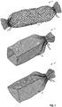
- FIG 1 different embodiments of the damping elements are depicted.
- the damping elements used for acoustic damping are formed as bags (1, 1', 1").
- the bags (1, 1', 1") provide a solution, where the shredded material is constrained inside the bags due to the wall structure of the bags.
- the bags (1, 1', 1") have a flexible and porous structure enabling ambient air to penetrate into the bags and the bags (1, 1', 1") have a netting structure of a material selected from the group belonging to thermoplastic or thermosetting plastic materials. Only one closing mean is depicted for the bag (1', 1"). This is done to indicate the cross section of the bag (1', 1"). A loop is used to show the sealing means for closing of the bag at it ends.
- figure 1 different geometrically shapes, e.g. tubular, rectangular or triangular, are depicted. Through the use of different shapes, it is possible to avoid incorporating cavities into a noise barrier comprising several bags stacked into the desired height.
- the shredded material is compressed and guided into the bags (1, 1', 1").
- the bags (1, 1', 1") packed with shredded material are to some extent able to change geometry without changing the density of the bag.
- the bags (1, 1', 1") can by applying a slight pressure be shaped to form relatively large contact surfaces between each other Even though the geometrical shape of the bags is changed, the density of the shredded material inside the bag is maintained.
- Each bag (1, 1', 1") is designed in such way, that the filled volume and the geometry are maintained over time.
- the bag (1, 1', 1") can contract in the radial direction, if the bag is exposed to tension force in the axial direction.
- all bags (1, 1', 1") have a flexible and porous structure enabling ambient air to penetrate.
- the bag (1, 1', 1") has a netting structure (2) made of a thermoplastic material or a thermosetting plastic material.
- the bag (1, 1', 1") can be made of elastic or non-elastic material formed into an open netting structure.
- the bag could also be made from a polymer non-woven, woven or knitted material.
- Figure 2 shows a noise barrier (10) for acoustic damping, comprising two bags (1, 1', 1") stacked on top of one another.
- the bags (1, 1', 1") are retained in their position by the use of retaining means (3) like metal, polymer or wood post.
- the two bags (1, 1', 1") are retained by four retaining means (3).
- the number of retaining means (3) can be adjusted.
- One or more partition elements can be positioned in between the bags.
- the noise barrier has three partition elements (11), where the partition elements are positioned at the top, bottom and near the midsection of the noise barrier instead of having several retaining means (3) positioned in front of and behind the bags.
- rods are speared through the bags.
- Figure 2 depicts that the bags (1, 1', 1") can have different lengths and diameters.
- the left side of the bags shows the cross section thereof.
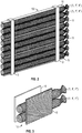
- Figure 3 shows a noise barrier (10) for acoustic damping according to a second embodiment.
- the noise barrier (10) for acoustic damping comprises a number of damping elements (1, 1', 1") and the damping elements are formed as bags (1, 1', 1") packed with shredded material, preferably recycled plastic granulate.
- FIG 3 only two bags (1, 1', 1") are depicted for the sake of simplicity. It is self-evident, that the number of bags stacked is depending on the desired height for the noise barrier and the diameter of the individual bags. It should be noted, that for the sake for simplicity only two bags of the type shown in figure 1 are depicted. The two bags in figure 3 are depicted with round cross sections.
- the noise barrier comprises several bags stacked into the desired height for the noise barrier.
- the bags (1, 1', 1") have a tubular shape, but as mentioned above other shapes are also applicable.
- the bags (1, 1', 1") are arranged between a front support element (5) and a rear support element (6), which elements are supporting the bags in their stacked position.
- the front support element (5) has an open structure, e.g. made of an acoustic absorptive material.
- the rear support element (6) can also be acoustic absorptive, however an acoustic reflective material can also be used, whereby the sound waves re-enter the bag (damping element) again.
- the noise barrier (10) for acoustic damping comprises a number of damping elements in the shape of bags (1, 1', 1"), which are arranged between a front support element (6) and a rear support element (7) for supporting the bags (1, 1', 1") in their stacked position.
- the front support element (6) comprises a number of guidance elements (8) for guiding the sound/noise into the bags (1, 1', 1").
- the guidance elements (8) would constitute a structure made of a plastic waste materials.
- the plastic waste materials could be used PVC pipes, where the used rigid pipes are cut into the desired length.
- the guidance elements (8) can be formed as a honeycomb structure or a pattern structure made from waste materials, where the structure consists of a number of interconnected circular pipe sections with varying diameter and/or length.
- a backing element (9) can be used for supporting the guidance element (8), constituting the pattern structure.
- the front support element (6) has an open structure, e.g. made from an acoustic absorptive material.
- the rear support has an open structure or would be made of an acoustic reflective material.
- damping elements formed as bags (1, 1', 1") made from an elastic material the size, geometry and number can be varied.
- the shredded material is mechanically constrained by the elastic netting structure of the bag (1, 1', 1").
- the density of the shredded material inside the bags can also be varied. Instead of just one row of bags, as depicted in figure 2-3 , the bags can be arranged in rows beside each other in the horizontal plan, as depicted in figures 4-5 .
- the shredded material inside the bags near the front support element (6) gets a relative low density compared to the density of the shredded material inside the bags near the rear support element.
- Another option can be to vary the density inside the bags, so that the bag at the bottom of the noise barrier has a lower density than the bag at the top, whereby the density is varying in the vertical direction for the noise barrier. As depicted in figures 4 and 5 the number of bags varying in both the horizontal direction and vertical direction.
- the damping elements (bags) are stacked in a vertical position on top of one another. In one embodiment, which is not shown, the damping elements (bags) are positioned horizontally beside one another.
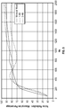
- Sound absorption coefficient also referred to as noise reduction coefficient (NRC)
- NRC noise reduction coefficient
- a value of zero indicates that the noise barrier is totally reflective and a value of one indicates that the material used for the noise barrier is totally absorptive.
- Most barriers are ranging from 0,6-0,9, corresponding to 60% - 90%.
- the sound damping properties of the material have been tested in a so called absorption tube with perpendicular sound incidence.
- the measurements were conducted in accordance with the standard DS/EN ISO 10534-2.
- the dimensions of the tube have the effect that only the frequency region between 50 Hz and 2000 Hz can be tested.
- Traffic noise primarily has frequency components in the region between 500 Hz and 2000 Hz, the measurements would give a fairly good indication of how good traffic noise is dampened.
- the measurements were conducted with a frequency resolution of 2 Hz in the frequency region 50 Hz - 2000 Hz, and the absorption coefficient determined was recalculated into 1/3 octave levels.
- the test samples were divided into 4 categories:
Landscapes
- Engineering & Computer Science (AREA)
- Architecture (AREA)
- Civil Engineering (AREA)
- Structural Engineering (AREA)
- Building Environments (AREA)
- Processing Of Solid Wastes (AREA)
- Soundproofing, Sound Blocking, And Sound Damping (AREA)
Claims (21)
- Beutelförmiges Dämpfungselement (1, 1', 1") zur Schalldämpfung in einer Lärmschutzwand, umfassend zerkleinertes Kunststoffmaterial, bevorzugt zerkleinerte, in den Beutel eingepackten Flocken, wobei der Beutel eine Oberflächenwand (2) aufweist, die eine mechanische Einschränkung des zerkleinerten Materials ermöglicht, wobei die Dichte des gepackten, zerkleinerten Materials im Beutel im Bereich von 200-600 kg/m3 ist, dadurch gekennzeichnet, dass das zerkleinerte Material ein zerkleinertes, faserverstärktes Verbundmaterial aus Glas- oder Karbonfasern ist, das in einem polymeren Matrixmaterial eingebettet oder begrenzt ist.
- Beutelförmiges Dämpfungselement (1, 1', 1") nach Anspruch 1, dadurch gekennzeichnet, dass das zerkleinerte Kunststoffmaterial im Beutel aus zerkleinerten Windturbinenschaufeln oder -gondeln gemacht ist.
- Beutelförmiges Dämpfungselement (1, 1', 1") nach Anspruch 1 oder 2, dadurch gekennzeichnet, dass der Beutel eine flexible und poröse Struktur hat, die ein Eindringen von Umgebungsluft in den Beutel ermöglicht, wobei der Beutel eine netzartige Struktur (2) hat aus einem Material, das zu der Gruppe Termoplast oder Duroplast gehört.
- Beutelförmiges Dämpfungselement (1, 1', 1") nach einem jeglichen der vorherstehenden Ansprüche, dadurch gekennzeichnet, dass die durchschnittliche Länge des zerkleinerten Materials zwischen 1-200 mm liegt.
- Beutelförmiges Dämpfungselement (1, 1', 1") nach den Ansprüchen 1 - 3, dadurch gekennzeichnet, dass die durchschnittliche Länge des zerkleinerten Materials zwischen 5-50 mm liegt.
- Beutelförmiges Dämpfungselement (1, 1', 1") nach einem jeglichen der vorherstehenden Ansprüche, dadurch gekennzeichnet, dass der Beutel verschiedene, geometrische Formen haben kann, z.B. rohrförmige (1), rechteckige (1') oder dreieckige Formen (1"), und aus UV- und wetterbeständigem Material bestehen kann.
- Beutelförmiges Dämpfungselement (1, 1', 1") nach einem jeglichen der vorherstehenden Ansprüche, dadurch gekennzeichnet, dass der Beutel aus einem unelastischen, gewobenen oder gestrickten, polymeren Material besteht, das von der Gruppe Polyester, Polyethylen, Polypropylen, Nylon usw. ausgewählt ist.
- Lärmschutzwand (10) zur Schalldämpfung umfassend ein vorderes Abstützelement (5), ein hinteres Abstützelement (4, 7) und einige beutelförmige Dämpfungselemente, dadurch gekennzeichnet, dass die Beutel (1, 1', 1") nach einem jeglichen der Ansprüche 1-7 ausgestaltet sind, wobei das vordere Abstützelement (5, 6) und das hintere Abstützelement (4, 7) in einer angemessenen Entfernung von einander angeordnet sind, wobei Beutel in wenigstens einer Reihe in der Lotrichtung zwischen dem vorderen Abstützelement und dem hinteren Abstützelement gestapelt sind.
- Lärmschutzwand (10) zur Schalldämpfung nach Anspruch 8, dadurch gekennzeichnet, dass die beutelförmigen Dämpfungselemente (1, 1', 1") in einer Reihe in der Lotrichtung der Lärmschutzwand (10) gestapelt sind.
- Lärmschutzwand (10) zur Schalldämpfung nach Anspruch 8, dadurch gekennzeichnet, dass die beutelförmigen Dämpfungselemente (1, 1', 1") in Reihen neben einander im waagerechten Plan zwischen dem vorderen Abstützelement und dem hinteren Abstützelement angeordnet sind.
- Lärmschutzwand (10) zur Schalldämpfung nach den Ansprüchen 8-10, dadurch gekennzeichnet, dass die Schalldämpfung geändert werden kann durch die Verwendung von wenigstens einem beutelförmigen Dämpfungselement (1, 1', 1") mit einer Dichte, die von der Dichte der anderen beutelförmigen Dämpfungselemente abweicht.
- Lärmschutzwand (10) zur Schalldämpfung nach den Ansprüchen 8-11, dadurch gekennzeichnet, dass das zerkleinerte Material in den beutelförmigen Dämpfungselementen (1, 1', 1") bei dem vorderen Abstützelement (5,6) eine relativ niedrige Dichte verglichen mit der Dichte des zerkleinerten Materials in den beutelförmigen Dämpfungselementen bei dem hinteren Abstützelement (4, 7) hat.
- Lärmschutzwand (10) zur Schalldämpfung nach den Ansprüchen 8-12, dadurch gekennzeichnet, dass das zerkleinerte, in den Beuteln gepackte Material (1, 1', 1") ein wiederverwertetes Abfallgut ist und eine Durchschnittslänge von zwischen 5-50 mm aufweist.
- Lärmschutzwand (10) zur Schalldämpfung nach den Ansprüchen 8-13, dadurch gekennzeichnet, dass das vordere Abstützelement (5,6) eine offene Netzstruktur aufweist.
- Lärmschutzwand (10) zur Schalldämpfung nach den Ansprüchen 8-14, dadurch gekennzeichnet, dass das vordere Abstützelement (5, 6) einige Anleitungselemente (8) umfasst für die Anleitung des Schalls/Lärms in die beutelförmigen Dämpfungselemente, wobei die Anleitungselemente eine Wabenstruktur aus offenen Rohrendstücken ausmachen.
- Lärmschutzwand (10) zur Schalldämpfung nach den Ansprüchen 8-15, dadurch gekennzeichnet, dass das zerkleinerte Material eine Mischung von zwei Verbundelementen umfasst, die aus einer Gruppe umfassend feste Lärmschutzwände, Windturbinen, und Windturbinengondeln ausgewählt werden.
- Lärmschutzwand (10) zur Schalldämpfung nach den Ansprüchen 8-16, dadurch gekennzeichnet, dass die beutelförmigen Dämpfungselemente (1, 1', 1") in Reihen neben einander im waagerechten Plan angeordnet sind.
- Lärmschutzwand (10) zur Schalldämpfung nach den Ansprüchen 8-17, dadurch gekennzeichnet, dass das hintere Abstützelement (4, 7) aus einem reflektierenden Material besteht.
- Lärmschutzwand (10) zur Schalldämpfung nach einem jeglichen der Ansprüche 8-18, dadurch gekennzeichnet, dass das hintere Abstützelement (4, 7) aus einem schallabsorbierenden Material besteht.
- Lärmschutzwand (10) zur Schalldämpfung nach einem jeglichen der Ansprüche 8-19, dadurch gekennzeichnet, dass das vordere Abstützelement (5, 6) eine offene Struktur aufweist.
- Verfahren zur Herstellung einer Lärmschutzwand (10) zur Schalldämpfung, das die folgenden Schritte umfasst:a) Aufrichten eines vorderen Abstützelements (5, 6) vor Ort,b) Aufrichten eines hinteren Abstützelements (4, 7) vor Ort,c) Sammeln und Sortieren eines zerkleinerten Abfallguts,d) Befüllen des zerkleinerten Abfallguts in die beutelförmigen Dämpfungselemente (1, 1', 1"),e) Transport der mit dem zerkleinerten Abfallgut befüllten Dämpfungselemente zum Aufstellungsort, undf) Anordnen der Dämpfungselemente zwischen dem vorderen Abstützelement (5, 6) und dem hinteren Abstützelement (4, 7),dadurch gekennzeichnet, dass die Füllung in den Dämpfungselementen ein zerkleinertes, faserverstärktes Verbundmaterial aus Glas- oder Karbonfasern ist, das in einem polymeren Matrixmaterial eingebettet oder begrenzt ist, und dass die Dichte des gepackten, zerkleinerten Materials in den Beuteln im Bereich von 200-600 kg/m3 ist.
Applications Claiming Priority (1)
| Application Number | Priority Date | Filing Date | Title |
|---|---|---|---|
| DKPA201600012A DK179008B1 (en) | 2016-01-08 | 2016-01-08 | A noise barrier for acoustic damping |
Publications (2)
| Publication Number | Publication Date |
|---|---|
| EP3190231A1 EP3190231A1 (de) | 2017-07-12 |
| EP3190231B1 true EP3190231B1 (de) | 2019-09-25 |
Family
ID=57737674
Family Applications (1)
| Application Number | Title | Priority Date | Filing Date |
|---|---|---|---|
| EP17150410.3A Active EP3190231B1 (de) | 2016-01-08 | 2017-01-05 | Dämpfender beutel zur schalldämpfung, lärmschutzwand damit und verfahren zur erstellung einer solchen lärmschutzwand |
Country Status (2)
| Country | Link |
|---|---|
| EP (1) | EP3190231B1 (de) |
| DK (1) | DK179008B1 (de) |
Families Citing this family (6)
| Publication number | Priority date | Publication date | Assignee | Title |
|---|---|---|---|---|
| DK179441B1 (da) † | 2015-10-30 | 2018-09-12 | Jesco Holding Aps | Granulatfyldt absorberende støjskærm |
| KR102193265B1 (ko) * | 2020-02-10 | 2020-12-24 | 성동훈 | 바람소멸기능을 갖춘 방음벽 |
| SK9236Y1 (sk) * | 2020-04-23 | 2021-07-14 | Forro Imrich | Izolačný podlahový materiál a spôsob jeho výroby |
| DK202100102U3 (da) * | 2021-11-17 | 2021-12-06 | Jesco Holding Aps | Indretning af støjskærm og etablering af en støjskærm |
| CN115158536B (zh) * | 2022-07-20 | 2023-12-22 | 中船黄埔文冲船舶有限公司 | 一种船用消音舱壁结构 |
| SE2330184A1 (en) * | 2023-04-26 | 2024-10-27 | Composite Design Sweden Ab | Sound berm made from reused composite wind turbine blades, and a method for manufacture thereof |
Citations (10)
| Publication number | Priority date | Publication date | Assignee | Title |
|---|---|---|---|---|
| GB2141756A (en) | 1983-03-19 | 1985-01-03 | James Walker | Sound deadening means |
| US5438171A (en) | 1992-01-22 | 1995-08-01 | Carsonite International Corporation | Composite sound wall |
| US5484970A (en) | 1993-06-07 | 1996-01-16 | Zeon Kasel Co., Ltd. | Acoustic insulator |
| EP0762382A1 (de) | 1994-05-23 | 1997-03-12 | ZEON KASEI Co. Ltd. | Platte zur realisierung einer schalldämmenden wand |
| US20040060770A1 (en) | 2002-10-01 | 2004-04-01 | Nifco Inc. | Sound absorbing device for fuel tank |
| WO2007146919A2 (en) | 2006-06-12 | 2007-12-21 | Schabel Polymer Technology, Llc | Lightweight pelletized materials |
| US20080121836A1 (en) | 2006-11-28 | 2008-05-29 | Bowman David J | Pourable insulation material |
| US20080135327A1 (en) | 2005-03-30 | 2008-06-12 | Toshiyuki Matsumura | Sound Absorbing Structure |
| WO2013076601A1 (en) | 2011-11-22 | 2013-05-30 | Wuertzen Jakob | Method of recycling fiberglass and/or carbon fibers for thermal insulation and/or sound insulation, use of particles for thermal cavity wall insulation, and a sound barrier panel |
| EP3162961B1 (de) | 2015-10-30 | 2018-10-24 | Jesco Holding ApS | Mit granulatgefüllte schalldämmende schutzwand |
-
2016
- 2016-01-08 DK DKPA201600012A patent/DK179008B1/en active
-
2017
- 2017-01-05 EP EP17150410.3A patent/EP3190231B1/de active Active
Patent Citations (10)
| Publication number | Priority date | Publication date | Assignee | Title |
|---|---|---|---|---|
| GB2141756A (en) | 1983-03-19 | 1985-01-03 | James Walker | Sound deadening means |
| US5438171A (en) | 1992-01-22 | 1995-08-01 | Carsonite International Corporation | Composite sound wall |
| US5484970A (en) | 1993-06-07 | 1996-01-16 | Zeon Kasel Co., Ltd. | Acoustic insulator |
| EP0762382A1 (de) | 1994-05-23 | 1997-03-12 | ZEON KASEI Co. Ltd. | Platte zur realisierung einer schalldämmenden wand |
| US20040060770A1 (en) | 2002-10-01 | 2004-04-01 | Nifco Inc. | Sound absorbing device for fuel tank |
| US20080135327A1 (en) | 2005-03-30 | 2008-06-12 | Toshiyuki Matsumura | Sound Absorbing Structure |
| WO2007146919A2 (en) | 2006-06-12 | 2007-12-21 | Schabel Polymer Technology, Llc | Lightweight pelletized materials |
| US20080121836A1 (en) | 2006-11-28 | 2008-05-29 | Bowman David J | Pourable insulation material |
| WO2013076601A1 (en) | 2011-11-22 | 2013-05-30 | Wuertzen Jakob | Method of recycling fiberglass and/or carbon fibers for thermal insulation and/or sound insulation, use of particles for thermal cavity wall insulation, and a sound barrier panel |
| EP3162961B1 (de) | 2015-10-30 | 2018-10-24 | Jesco Holding ApS | Mit granulatgefüllte schalldämmende schutzwand |
Non-Patent Citations (2)
| Title |
|---|
| "RecyBlade", 1 January 2014, article ANONYMOUS: "Report of recycling of wind turbine blades ''Miljøprojekt nr. 1551, 2014", pages: 1 - 43, XP055764524 |
| "Report of recycling of glass fiber materials 'Miljøprojekt nr. 1455, 2012", 1 January 2012, article ANONYMOUS: "Genanvendelse af glasfibermateriale Miljøprojekt nr. 1455, 2012", pages: 1 - 26, XP055764529 |
Also Published As
| Publication number | Publication date |
|---|---|
| DK179008B1 (en) | 2017-08-07 |
| EP3190231A1 (de) | 2017-07-12 |
| DK201600012A1 (en) | 2017-07-24 |
Similar Documents
| Publication | Publication Date | Title |
|---|---|---|
| EP3190231B1 (de) | Dämpfender beutel zur schalldämpfung, lärmschutzwand damit und verfahren zur erstellung einer solchen lärmschutzwand | |
| Arenas et al. | Eco-materials with noise reduction properties | |
| US3983956A (en) | Noise reduction barrier | |
| KR20030041959A (ko) | 섬유강화 플라스틱제 방음벽 및 그 제조방법 | |
| EP2875506B1 (de) | Schalldämpfende vorrichtung mit mindestens einem hohlraumresonator | |
| US6705268B2 (en) | Engine noise barrier | |
| RU2360080C1 (ru) | Многослойная акустическая панель | |
| DE212019000455U1 (de) | Schallisolierendes Paneel | |
| EP3162961B1 (de) | Mit granulatgefüllte schalldämmende schutzwand | |
| CA2095919A1 (en) | Noise attenuation panel | |
| KR102669619B1 (ko) | 층간소음 저감장치 | |
| US11887573B2 (en) | Sound insulation element | |
| Gieva et al. | Comparative analysis of the acoustic efficiency of classical and sonic crystal noise barriers | |
| JPH10299115A (ja) | 吸音材、及び吸音装置、並びに吸音材取付工法 | |
| JP2006152785A (ja) | 吸音板及びその吸音方法並びに設置方法 | |
| JPH04281905A (ja) | 吸音体及びこの吸音体を用いた吸音パネル | |
| Yeşilyurt | Enhancing sound transmission loss of polyurethane foams using waste soda glass filler | |
| JP3391664B2 (ja) | 給水配管又は給湯配管の防音構造 | |
| KR102193265B1 (ko) | 바람소멸기능을 갖춘 방음벽 | |
| KR200480057Y1 (ko) | 미세 타공판 및 이를 이용한 방음장치 | |
| EP4183928A1 (de) | Lärmschutzwand und verfahren zur herstellung einer lärmschutzwand | |
| WO1997024492A1 (es) | Pantallas acústicas absorbentes con granza de caucho | |
| CN208455510U (zh) | 一种采用细砂吸声的声屏障单元板 | |
| EP0667416B1 (de) | Lärmschutzwand | |
| US20250065603A1 (en) | Multimaterial sheet |
Legal Events
| Date | Code | Title | Description |
|---|---|---|---|
| PUAI | Public reference made under article 153(3) epc to a published international application that has entered the european phase |
Free format text: ORIGINAL CODE: 0009012 |
|
| STAA | Information on the status of an ep patent application or granted ep patent |
Free format text: STATUS: THE APPLICATION HAS BEEN PUBLISHED |
|
| AK | Designated contracting states |
Kind code of ref document: A1 Designated state(s): AL AT BE BG CH CY CZ DE DK EE ES FI FR GB GR HR HU IE IS IT LI LT LU LV MC MK MT NL NO PL PT RO RS SE SI SK SM TR |
|
| AX | Request for extension of the european patent |
Extension state: BA ME |
|
| STAA | Information on the status of an ep patent application or granted ep patent |
Free format text: STATUS: REQUEST FOR EXAMINATION WAS MADE |
|
| 17P | Request for examination filed |
Effective date: 20171109 |
|
| RBV | Designated contracting states (corrected) |
Designated state(s): AL AT BE BG CH CY CZ DE DK EE ES FI FR GB GR HR HU IE IS IT LI LT LU LV MC MK MT NL NO PL PT RO RS SE SI SK SM TR |
|
| STAA | Information on the status of an ep patent application or granted ep patent |
Free format text: STATUS: EXAMINATION IS IN PROGRESS |
|
| 17Q | First examination report despatched |
Effective date: 20180301 |
|
| GRAP | Despatch of communication of intention to grant a patent |
Free format text: ORIGINAL CODE: EPIDOSNIGR1 |
|
| STAA | Information on the status of an ep patent application or granted ep patent |
Free format text: STATUS: GRANT OF PATENT IS INTENDED |
|
| INTG | Intention to grant announced |
Effective date: 20190418 |
|
| GRAS | Grant fee paid |
Free format text: ORIGINAL CODE: EPIDOSNIGR3 |
|
| GRAA | (expected) grant |
Free format text: ORIGINAL CODE: 0009210 |
|
| STAA | Information on the status of an ep patent application or granted ep patent |
Free format text: STATUS: THE PATENT HAS BEEN GRANTED |
|
| AK | Designated contracting states |
Kind code of ref document: B1 Designated state(s): AL AT BE BG CH CY CZ DE DK EE ES FI FR GB GR HR HU IE IS IT LI LT LU LV MC MK MT NL NO PL PT RO RS SE SI SK SM TR |
|
| REG | Reference to a national code |
Ref country code: GB Ref legal event code: FG4D |
|
| REG | Reference to a national code |
Ref country code: CH Ref legal event code: EP |
|
| REG | Reference to a national code |
Ref country code: AT Ref legal event code: REF Ref document number: 1183944 Country of ref document: AT Kind code of ref document: T Effective date: 20191015 |
|
| REG | Reference to a national code |
Ref country code: IE Ref legal event code: FG4D |
|
| REG | Reference to a national code |
Ref country code: DE Ref legal event code: R096 Ref document number: 602017007216 Country of ref document: DE |
|
| REG | Reference to a national code |
Ref country code: NL Ref legal event code: FP |
|
| PG25 | Lapsed in a contracting state [announced via postgrant information from national office to epo] |
Ref country code: NO Free format text: LAPSE BECAUSE OF FAILURE TO SUBMIT A TRANSLATION OF THE DESCRIPTION OR TO PAY THE FEE WITHIN THE PRESCRIBED TIME-LIMIT Effective date: 20191225 Ref country code: FI Free format text: LAPSE BECAUSE OF FAILURE TO SUBMIT A TRANSLATION OF THE DESCRIPTION OR TO PAY THE FEE WITHIN THE PRESCRIBED TIME-LIMIT Effective date: 20190925 Ref country code: BG Free format text: LAPSE BECAUSE OF FAILURE TO SUBMIT A TRANSLATION OF THE DESCRIPTION OR TO PAY THE FEE WITHIN THE PRESCRIBED TIME-LIMIT Effective date: 20191225 Ref country code: SE Free format text: LAPSE BECAUSE OF FAILURE TO SUBMIT A TRANSLATION OF THE DESCRIPTION OR TO PAY THE FEE WITHIN THE PRESCRIBED TIME-LIMIT Effective date: 20190925 Ref country code: HR Free format text: LAPSE BECAUSE OF FAILURE TO SUBMIT A TRANSLATION OF THE DESCRIPTION OR TO PAY THE FEE WITHIN THE PRESCRIBED TIME-LIMIT Effective date: 20190925 Ref country code: LT Free format text: LAPSE BECAUSE OF FAILURE TO SUBMIT A TRANSLATION OF THE DESCRIPTION OR TO PAY THE FEE WITHIN THE PRESCRIBED TIME-LIMIT Effective date: 20190925 |
|
| REG | Reference to a national code |
Ref country code: LT Ref legal event code: MG4D |
|
| PG25 | Lapsed in a contracting state [announced via postgrant information from national office to epo] |
Ref country code: RS Free format text: LAPSE BECAUSE OF FAILURE TO SUBMIT A TRANSLATION OF THE DESCRIPTION OR TO PAY THE FEE WITHIN THE PRESCRIBED TIME-LIMIT Effective date: 20190925 Ref country code: LV Free format text: LAPSE BECAUSE OF FAILURE TO SUBMIT A TRANSLATION OF THE DESCRIPTION OR TO PAY THE FEE WITHIN THE PRESCRIBED TIME-LIMIT Effective date: 20190925 Ref country code: GR Free format text: LAPSE BECAUSE OF FAILURE TO SUBMIT A TRANSLATION OF THE DESCRIPTION OR TO PAY THE FEE WITHIN THE PRESCRIBED TIME-LIMIT Effective date: 20191226 |
|
| REG | Reference to a national code |
Ref country code: AT Ref legal event code: MK05 Ref document number: 1183944 Country of ref document: AT Kind code of ref document: T Effective date: 20190925 |
|
| PG25 | Lapsed in a contracting state [announced via postgrant information from national office to epo] |
Ref country code: PL Free format text: LAPSE BECAUSE OF FAILURE TO SUBMIT A TRANSLATION OF THE DESCRIPTION OR TO PAY THE FEE WITHIN THE PRESCRIBED TIME-LIMIT Effective date: 20190925 Ref country code: ES Free format text: LAPSE BECAUSE OF FAILURE TO SUBMIT A TRANSLATION OF THE DESCRIPTION OR TO PAY THE FEE WITHIN THE PRESCRIBED TIME-LIMIT Effective date: 20190925 Ref country code: PT Free format text: LAPSE BECAUSE OF FAILURE TO SUBMIT A TRANSLATION OF THE DESCRIPTION OR TO PAY THE FEE WITHIN THE PRESCRIBED TIME-LIMIT Effective date: 20200127 Ref country code: AL Free format text: LAPSE BECAUSE OF FAILURE TO SUBMIT A TRANSLATION OF THE DESCRIPTION OR TO PAY THE FEE WITHIN THE PRESCRIBED TIME-LIMIT Effective date: 20190925 Ref country code: EE Free format text: LAPSE BECAUSE OF FAILURE TO SUBMIT A TRANSLATION OF THE DESCRIPTION OR TO PAY THE FEE WITHIN THE PRESCRIBED TIME-LIMIT Effective date: 20190925 Ref country code: RO Free format text: LAPSE BECAUSE OF FAILURE TO SUBMIT A TRANSLATION OF THE DESCRIPTION OR TO PAY THE FEE WITHIN THE PRESCRIBED TIME-LIMIT Effective date: 20190925 Ref country code: IT Free format text: LAPSE BECAUSE OF FAILURE TO SUBMIT A TRANSLATION OF THE DESCRIPTION OR TO PAY THE FEE WITHIN THE PRESCRIBED TIME-LIMIT Effective date: 20190925 Ref country code: AT Free format text: LAPSE BECAUSE OF FAILURE TO SUBMIT A TRANSLATION OF THE DESCRIPTION OR TO PAY THE FEE WITHIN THE PRESCRIBED TIME-LIMIT Effective date: 20190925 |
|
| PG25 | Lapsed in a contracting state [announced via postgrant information from national office to epo] |
Ref country code: CZ Free format text: LAPSE BECAUSE OF FAILURE TO SUBMIT A TRANSLATION OF THE DESCRIPTION OR TO PAY THE FEE WITHIN THE PRESCRIBED TIME-LIMIT Effective date: 20190925 Ref country code: SM Free format text: LAPSE BECAUSE OF FAILURE TO SUBMIT A TRANSLATION OF THE DESCRIPTION OR TO PAY THE FEE WITHIN THE PRESCRIBED TIME-LIMIT Effective date: 20190925 Ref country code: IS Free format text: LAPSE BECAUSE OF FAILURE TO SUBMIT A TRANSLATION OF THE DESCRIPTION OR TO PAY THE FEE WITHIN THE PRESCRIBED TIME-LIMIT Effective date: 20200224 Ref country code: SK Free format text: LAPSE BECAUSE OF FAILURE TO SUBMIT A TRANSLATION OF THE DESCRIPTION OR TO PAY THE FEE WITHIN THE PRESCRIBED TIME-LIMIT Effective date: 20190925 |
|
| REG | Reference to a national code |
Ref country code: DE Ref legal event code: R026 Ref document number: 602017007216 Country of ref document: DE |
|
| PLBI | Opposition filed |
Free format text: ORIGINAL CODE: 0009260 |
|
| PLAX | Notice of opposition and request to file observation + time limit sent |
Free format text: ORIGINAL CODE: EPIDOSNOBS2 |
|
| PG2D | Information on lapse in contracting state deleted |
Ref country code: IS |
|
| PG25 | Lapsed in a contracting state [announced via postgrant information from national office to epo] |
Ref country code: IS Free format text: LAPSE BECAUSE OF FAILURE TO SUBMIT A TRANSLATION OF THE DESCRIPTION OR TO PAY THE FEE WITHIN THE PRESCRIBED TIME-LIMIT Effective date: 20200126 Ref country code: DK Free format text: LAPSE BECAUSE OF FAILURE TO SUBMIT A TRANSLATION OF THE DESCRIPTION OR TO PAY THE FEE WITHIN THE PRESCRIBED TIME-LIMIT Effective date: 20190925 |
|
| 26 | Opposition filed |
Opponent name: JESCO HOLDING APS Effective date: 20200625 |
|
| PG25 | Lapsed in a contracting state [announced via postgrant information from national office to epo] |
Ref country code: MC Free format text: LAPSE BECAUSE OF FAILURE TO SUBMIT A TRANSLATION OF THE DESCRIPTION OR TO PAY THE FEE WITHIN THE PRESCRIBED TIME-LIMIT Effective date: 20190925 |
|
| REG | Reference to a national code |
Ref country code: CH Ref legal event code: PL |
|
| REG | Reference to a national code |
Ref country code: BE Ref legal event code: MM Effective date: 20200131 |
|
| PG25 | Lapsed in a contracting state [announced via postgrant information from national office to epo] |
Ref country code: LU Free format text: LAPSE BECAUSE OF NON-PAYMENT OF DUE FEES Effective date: 20200105 |
|
| PLBB | Reply of patent proprietor to notice(s) of opposition received |
Free format text: ORIGINAL CODE: EPIDOSNOBS3 |
|
| PG25 | Lapsed in a contracting state [announced via postgrant information from national office to epo] |
Ref country code: LI Free format text: LAPSE BECAUSE OF NON-PAYMENT OF DUE FEES Effective date: 20200131 Ref country code: SI Free format text: LAPSE BECAUSE OF FAILURE TO SUBMIT A TRANSLATION OF THE DESCRIPTION OR TO PAY THE FEE WITHIN THE PRESCRIBED TIME-LIMIT Effective date: 20190925 Ref country code: CH Free format text: LAPSE BECAUSE OF NON-PAYMENT OF DUE FEES Effective date: 20200131 Ref country code: BE Free format text: LAPSE BECAUSE OF NON-PAYMENT OF DUE FEES Effective date: 20200131 |
|
| PG25 | Lapsed in a contracting state [announced via postgrant information from national office to epo] |
Ref country code: IE Free format text: LAPSE BECAUSE OF NON-PAYMENT OF DUE FEES Effective date: 20200105 |
|
| PLAB | Opposition data, opponent's data or that of the opponent's representative modified |
Free format text: ORIGINAL CODE: 0009299OPPO |
|
| R26 | Opposition filed (corrected) |
Opponent name: JESCO HOLDING APS Effective date: 20200625 |
|
| GBPC | Gb: european patent ceased through non-payment of renewal fee |
Effective date: 20210105 |
|
| PG25 | Lapsed in a contracting state [announced via postgrant information from national office to epo] |
Ref country code: GB Free format text: LAPSE BECAUSE OF NON-PAYMENT OF DUE FEES Effective date: 20210105 |
|
| PLCK | Communication despatched that opposition was rejected |
Free format text: ORIGINAL CODE: EPIDOSNREJ1 |
|
| PG25 | Lapsed in a contracting state [announced via postgrant information from national office to epo] |
Ref country code: TR Free format text: LAPSE BECAUSE OF FAILURE TO SUBMIT A TRANSLATION OF THE DESCRIPTION OR TO PAY THE FEE WITHIN THE PRESCRIBED TIME-LIMIT Effective date: 20190925 Ref country code: MT Free format text: LAPSE BECAUSE OF FAILURE TO SUBMIT A TRANSLATION OF THE DESCRIPTION OR TO PAY THE FEE WITHIN THE PRESCRIBED TIME-LIMIT Effective date: 20190925 Ref country code: CY Free format text: LAPSE BECAUSE OF FAILURE TO SUBMIT A TRANSLATION OF THE DESCRIPTION OR TO PAY THE FEE WITHIN THE PRESCRIBED TIME-LIMIT Effective date: 20190925 |
|
| APAH | Appeal reference modified |
Free format text: ORIGINAL CODE: EPIDOSCREFNO |
|
| APBM | Appeal reference recorded |
Free format text: ORIGINAL CODE: EPIDOSNREFNO |
|
| APBP | Date of receipt of notice of appeal recorded |
Free format text: ORIGINAL CODE: EPIDOSNNOA2O |
|
| PG25 | Lapsed in a contracting state [announced via postgrant information from national office to epo] |
Ref country code: MK Free format text: LAPSE BECAUSE OF FAILURE TO SUBMIT A TRANSLATION OF THE DESCRIPTION OR TO PAY THE FEE WITHIN THE PRESCRIBED TIME-LIMIT Effective date: 20190925 |
|
| APBU | Appeal procedure closed |
Free format text: ORIGINAL CODE: EPIDOSNNOA9O |
|
| REG | Reference to a national code |
Ref country code: DE Ref legal event code: R100 Ref document number: 602017007216 Country of ref document: DE |
|
| PLBN | Opposition rejected |
Free format text: ORIGINAL CODE: 0009273 |
|
| STAA | Information on the status of an ep patent application or granted ep patent |
Free format text: STATUS: OPPOSITION REJECTED |
|
| 27O | Opposition rejected |
Effective date: 20220706 |
|
| PG25 | Lapsed in a contracting state [announced via postgrant information from national office to epo] |
Ref country code: IS Free format text: LAPSE BECAUSE OF NON-PAYMENT OF DUE FEES Effective date: 20200224 |
|
| PGFP | Annual fee paid to national office [announced via postgrant information from national office to epo] |
Ref country code: NL Payment date: 20260120 Year of fee payment: 10 |
|
| PGFP | Annual fee paid to national office [announced via postgrant information from national office to epo] |
Ref country code: DE Payment date: 20260122 Year of fee payment: 10 |
|
| PGFP | Annual fee paid to national office [announced via postgrant information from national office to epo] |
Ref country code: FR Payment date: 20260120 Year of fee payment: 10 |