EP3190323B1 - Stromventil - Google Patents
Stromventil Download PDFInfo
- Publication number
- EP3190323B1 EP3190323B1 EP16184241.4A EP16184241A EP3190323B1 EP 3190323 B1 EP3190323 B1 EP 3190323B1 EP 16184241 A EP16184241 A EP 16184241A EP 3190323 B1 EP3190323 B1 EP 3190323B1
- Authority
- EP
- European Patent Office
- Prior art keywords
- valve body
- control member
- face
- valve
- cover
- Prior art date
- Legal status (The legal status is an assumption and is not a legal conclusion. Google has not performed a legal analysis and makes no representation as to the accuracy of the status listed.)
- Not-in-force
Links
Images




Classifications
-
- F—MECHANICAL ENGINEERING; LIGHTING; HEATING; WEAPONS; BLASTING
- F16—ENGINEERING ELEMENTS AND UNITS; GENERAL MEASURES FOR PRODUCING AND MAINTAINING EFFECTIVE FUNCTIONING OF MACHINES OR INSTALLATIONS; THERMAL INSULATION IN GENERAL
- F16K—VALVES; TAPS; COCKS; ACTUATING-FLOATS; DEVICES FOR VENTING OR AERATING
- F16K17/00—Safety valves; Equalising valves, e.g. pressure relief valves
- F16K17/20—Excess-flow valves
- F16K17/22—Excess-flow valves actuated by the difference of pressure between two places in the flow line
- F16K17/24—Excess-flow valves actuated by the difference of pressure between two places in the flow line acting directly on the cutting-off member
- F16K17/28—Excess-flow valves actuated by the difference of pressure between two places in the flow line acting directly on the cutting-off member operating in one direction only
-
- F—MECHANICAL ENGINEERING; LIGHTING; HEATING; WEAPONS; BLASTING
- F16—ENGINEERING ELEMENTS AND UNITS; GENERAL MEASURES FOR PRODUCING AND MAINTAINING EFFECTIVE FUNCTIONING OF MACHINES OR INSTALLATIONS; THERMAL INSULATION IN GENERAL
- F16K—VALVES; TAPS; COCKS; ACTUATING-FLOATS; DEVICES FOR VENTING OR AERATING
- F16K17/00—Safety valves; Equalising valves, e.g. pressure relief valves
- F16K17/20—Excess-flow valves
- F16K17/34—Excess-flow valves in which the flow-energy of the flowing medium actuates the closing mechanism
-
- F—MECHANICAL ENGINEERING; LIGHTING; HEATING; WEAPONS; BLASTING
- F16—ENGINEERING ELEMENTS AND UNITS; GENERAL MEASURES FOR PRODUCING AND MAINTAINING EFFECTIVE FUNCTIONING OF MACHINES OR INSTALLATIONS; THERMAL INSULATION IN GENERAL
- F16K—VALVES; TAPS; COCKS; ACTUATING-FLOATS; DEVICES FOR VENTING OR AERATING
- F16K15/00—Check valves
- F16K15/14—Check valves with flexible valve members
- F16K15/148—Check valves with flexible valve members the closure elements being fixed in their centre
-
- F—MECHANICAL ENGINEERING; LIGHTING; HEATING; WEAPONS; BLASTING
- F16—ENGINEERING ELEMENTS AND UNITS; GENERAL MEASURES FOR PRODUCING AND MAINTAINING EFFECTIVE FUNCTIONING OF MACHINES OR INSTALLATIONS; THERMAL INSULATION IN GENERAL
- F16K—VALVES; TAPS; COCKS; ACTUATING-FLOATS; DEVICES FOR VENTING OR AERATING
- F16K17/00—Safety valves; Equalising valves, e.g. pressure relief valves
- F16K17/02—Safety valves; Equalising valves, e.g. pressure relief valves opening on surplus pressure on one side; closing on insufficient pressure on one side
- F16K17/168—Safety valves; Equalising valves, e.g. pressure relief valves opening on surplus pressure on one side; closing on insufficient pressure on one side combined with manually-controlled valves, e.g. a valve combined with a safety valve
-
- G—PHYSICS
- G05—CONTROLLING; REGULATING
- G05D—SYSTEMS FOR CONTROLLING OR REGULATING NON-ELECTRIC VARIABLES
- G05D7/00—Control of flow
- G05D7/01—Control of flow without auxiliary power
- G05D7/0106—Control of flow without auxiliary power the sensing element being a flexible member, e.g. bellows, diaphragm, capsule
- G05D7/0113—Control of flow without auxiliary power the sensing element being a flexible member, e.g. bellows, diaphragm, capsule the sensing element acting as a valve
-
- G—PHYSICS
- G05—CONTROLLING; REGULATING
- G05D—SYSTEMS FOR CONTROLLING OR REGULATING NON-ELECTRIC VARIABLES
- G05D7/00—Control of flow
- G05D7/01—Control of flow without auxiliary power
- G05D7/0106—Control of flow without auxiliary power the sensing element being a flexible member, e.g. bellows, diaphragm, capsule
- G05D7/012—Control of flow without auxiliary power the sensing element being a flexible member, e.g. bellows, diaphragm, capsule the sensing element being deformable and acting as a valve
-
- Y—GENERAL TAGGING OF NEW TECHNOLOGICAL DEVELOPMENTS; GENERAL TAGGING OF CROSS-SECTIONAL TECHNOLOGIES SPANNING OVER SEVERAL SECTIONS OF THE IPC; TECHNICAL SUBJECTS COVERED BY FORMER USPC CROSS-REFERENCE ART COLLECTIONS [XRACs] AND DIGESTS
- Y10—TECHNICAL SUBJECTS COVERED BY FORMER USPC
- Y10T—TECHNICAL SUBJECTS COVERED BY FORMER US CLASSIFICATION
- Y10T137/00—Fluid handling
- Y10T137/7722—Line condition change responsive valves
- Y10T137/7837—Direct response valves [i.e., check valve type]
- Y10T137/7838—Plural
- Y10T137/7839—Dividing and recombining in a single flow path
- Y10T137/784—Integral resilient member forms plural valves
-
- Y—GENERAL TAGGING OF NEW TECHNOLOGICAL DEVELOPMENTS; GENERAL TAGGING OF CROSS-SECTIONAL TECHNOLOGIES SPANNING OVER SEVERAL SECTIONS OF THE IPC; TECHNICAL SUBJECTS COVERED BY FORMER USPC CROSS-REFERENCE ART COLLECTIONS [XRACs] AND DIGESTS
- Y10—TECHNICAL SUBJECTS COVERED BY FORMER USPC
- Y10T—TECHNICAL SUBJECTS COVERED BY FORMER US CLASSIFICATION
- Y10T137/00—Fluid handling
- Y10T137/7722—Line condition change responsive valves
- Y10T137/7837—Direct response valves [i.e., check valve type]
- Y10T137/7869—Biased open
Definitions
- the present invention relates to a control valve and, more particularly, to a flow control valve for a pipeline.
- a pipeline is used to convey water, oil or gas.
- the pipeline is subjected to a determined pressure.
- the pressure applied on the pipeline exceeds a predetermined value, the pipeline is broken easily.
- the pipeline is not provided with such a control device, thereby causing a danger or an accident
- a flow control valve comprising a valve body, a control member and a cover.
- the valve body has an interior provided with a receiving space for receiving the control member and the cover.
- the receiving space of the valve body has a bottom having a periphery provided with a resting face and having a central position provided with a shaft portion for positioning the control member.
- the shaft portion of the valve body has a bottom provided with a stepped face, and a positioning groove is defined between the stepped face and the resting face.
- the positioning groove of the valve body is provided with a plurality of water outlet holes that are arranged in a radiating manner and are equally distant from each other.
- the control member has a central position provided with a hollow bushing mounted on the shaft portion of the valve body.
- the bushing of the control member has an interior having a bottom face provided with an abutment corresponding to a top face of the shaft portion.
- a top of the bushing extends downward to present an arcuate shape.
- the control member is provided with an elastic portion corresponding to the stepped face of the valve body.
- the elastic portion of the control member is contracted inward and expanded outward.
- the control member is provided with a positioning projection corresponding to the positioning groove of the valve body.
- the control member is provided with a sealing portion corresponding to the resting face of the valve body.
- the sealing portion of the control member is provided with an abutting face.
- the cover covers an upper portion of the valve body.
- the cover has a central position provided with a flange mounted on the bushing of the control member.
- the cover has a periphery provided with a plurality of water inlet holes connected to the receiving space of the valve body.
- the elastic portion of the control member when the pressure of the fluid exceeds a determined value, the elastic portion of the control member is expanded outward and smoothly abuts the stepped face of the valve body, so that the abutting face of the sealing portion of the control member presses the resting face of the valve body tightly and closely, to seal the water outlet holes of the valve body, so that the fluid is interrupted and cannot flow outward from the water outlet holes of the valve body, to prevent the water pipe from being broken due to an excessive pressure, thereby achieving the purpose of controlling the flow rate and preventing the water pipe from being broken.
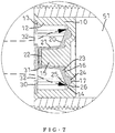
- a flow control valve in accordance with the preferred embodiment of the present invention comprises a valve body 10, a control member 20 and a cover 30.
- the valve body 10 has an interior provided with a receiving space 11 for receiving the control member 20 and the cover 30.
- the receiving space 11 of the valve body 10 has a bottom having a periphery provided with a resting face 14 and having a central position provided with a shaft portion 15 for positioning the control member 20.
- the shaft portion 15 of the valve body 10 has a bottom provided with a flat stepped face 16, and a positioning groove 17 is defined between the stepped face 16 and the resting face 14.
- the positioning groove 17 of the valve body 10 is provided with a plurality of water outlet holes 18 that are arranged in a radiating manner and are equally distant from each other so that a fluid is evenly diffused from the resting face 14 of the valve body 10 and flows outward from the water outlet holes 18 of the valve body 10.
- the control member 20 has a central position provided with a hollow bushing 21 mounted on the shaft portion 15 of the valve body 10.
- the bushing 21 of the control member 20 has an interior having a bottom face provided with a slightly projecting abutment 22 corresponding to a top face of the shaft portion 15.
- a top of the bushing 21 extends downward to present an arcuate shape.
- the control member 20 is provided with an elastic portion 23 corresponding to the stepped face 16 of the valve body 10.
- the elastic portion 23 of the control member 20 is contracted inward and expanded outward to present an elastic deformation.
- the control member 20 is provided with a positioning projection 24 corresponding to the positioning groove 17 of the valve body 10.
- the positioning projection 24 of the control member 20 has a shape and a size conforming to that of the positioning groove 17 of the valve body 10.
- the control member 20 is provided with a sealing portion 25 corresponding to the resting face 14 of the valve body 10.
- the sealing portion 25 of the control member 20 is provided with an abutting face 26.
- the elastic portion 23 of the control member 20 When the flow pressure of the fluid is under an abnormal condition, the elastic portion 23 of the control member 20 is expanded outward and abuts the stepped face 16 of the valve body 10, so that the abutting face 26 of the sealing portion 25 of the control member 20 abuts the resting face 14 of the valve body 10 tightly and closely, to seal the water outlet holes 18 of the valve body 10, and to prevent the fluid from flowing outward from the water outlet holes 18 of the valve body 10.
- the cover 30 covers an upper portion of the valve body 10.
- the cover 30 has a central position provided with a flange 31 mounted on the bushing 21 of the control member 20.
- the cover 30 has a periphery provided with a plurality of water inlet holes 32 connected to the receiving space 11 of the valve body 10.
- the water inlet holes 32 of the cover 30 are equally distant from each other so that the fluid evenly flows from the water inlet holes 32 of the cover 30 into the receiving space 11 of the valve body 10.
- each of the valve body 10 and the cover 30 is made of fiber reinforced plastics (FRP).
- the control member 20 is made of an elastically deformable material, such as silicone or rubber.
- Each of the positioning groove 17 of the valve body 10 and the positioning projection 24 of the control member 20 has a substantially semi-circular shape.
- Each of the shaft portion 15 of the valve body 10 and the bushing 21 of the control member 20 has a substantially conical shape with a smaller upper end and a larger lower end.
- the receiving space 11 of the valve body 10 has an inner wall provided with a plurality of ribs 12 that are arranged in a longitudinal direction.
- Each of the ribs 12 has an upper end defining a space to form a stepped edge 13 for placing the cover 30.
- the resting face 14 of the valve body 10 has an inclined shape with a higher outer portion and a lower inner portion.
- the upper portion of the valve body 10 is provided with an enlarged stop edge 19 for positioning the valve body 10 in a pipeline or a coupling.
- a faucet (not shown) of a sink has a lower end provided with a water pipe 40 and a coupling 41.
- a water inlet pipe 1 is mounted in a wall.
- a three-way connector 50 is mounted between the water inlet pipe 1 and the coupling 41.
- the three-way connector 50 includes a first pipe 51 locked into the water inlet pipe 1, a second pipe 52 locked into the coupling 41 and a third pipe 53 provided with a switch 54.
- the switch 54 is movable between a first position where the first pipe 51 is connected to the second pipe 52 so that the water in the water inlet pipe 1 can flow through the first pipe 51, the second pipe 52 and the water pipe 40 into the faucet, and a second position where the first pipe 51 is disconnected from the second pipe 52 so that the water in the water inlet pipe 1 is interrupted and cannot flow into the faucet.
- the flow control valve is selectively mounted in the first pipe 51 of the three-way connector 50.
- the fluid evenly flows from the water inlet holes 32 of the cover 30 into the receiving space 11 of the valve body 10, and then flows through the water outlet holes 18 of the valve body 10, the first pipe 51, the second pipe 52 and the water pipe 40 into the faucet.
- the elastic portion 23 of the control member 20 is contracted inward, so that the abutting face 26 of the sealing portion 25 of the control member 20 is disposed at the open state.
- a fitting 42 is mounted between the second pipe 52 of the three-way connector 50 and the coupling 41, and the flow control valve is selectively mounted in the fitting 42.
- the flow pressure of the fluid When the flow pressure of the fluid is under the normal condition, the fluid flows through the first pipe 51 into the second pipe 52, then evenly flows from the water inlet holes 32 of the cover 30 into the receiving space 11 of the valve body 10, and then flows through the water outlet holes 18 of the valve body 10 and the water pipe 40 into the faucet.
- the elastic portion 23 of the control member 20 is expanded outward and smoothly abuts the stepped face 16 of the valve body 10, so that the abutting face 26 of the sealing portion 25 of the control member 20 presses the resting face 14 of the valve body 10 tightly and closely, to seal the water outlet holes 18 of the valve body 10, so that the fluid is interrupted and cannot flow outward from the water outlet holes 18 of the valve body 10, to prevent the water pipe 40 from being broken due to an excessive pressure, thereby achieving the purpose of controlling the flow rate and preventing the water pipe 40 from being broken.
Landscapes
- Engineering & Computer Science (AREA)
- General Engineering & Computer Science (AREA)
- Mechanical Engineering (AREA)
- Physics & Mathematics (AREA)
- General Physics & Mathematics (AREA)
- Automation & Control Theory (AREA)
- Safety Valves (AREA)
- Lift Valve (AREA)
Claims (8)
- Stromventil, aufweisend:einen Ventilkörper (10), ein Steuerelement (20) und eine Abdeckung (30);wobei:der Ventilkörper einen Innenraum aufweist, der mit einem Aufnahmeraum (11) zum Aufnehmen des Steuerelements und der Abdeckung versehen ist;der Aufnahmeraum des Ventilkörpers einen Boden mit einem Umfang hat, der mit einer Auflagefläche (14) versehen ist und eine zentrale Stelle aufweist, die mit einem Schaftabschnitt (15) zum Positionieren des Steuerelements versehen ist;der Schaftabschnitt des Ventilkörpers einen Boden hat, der mit einer abgestuften Fläche (16) versehen ist, und eine Positionierungsnut (17) zwischen der abgestuften Fläche und der Auflagefläche definiert ist;die Positionierungsnut des Ventilkörpers mit einer Mehrzahl von Wasserauslassöffnungen (18) versehen ist, die strahlenförmig angeordnet sind und gleich weit voneinander beabstandet sind;das Steuerglied eine zentrale Stelle hat, die mit einer hohlen Buchse (21) versehen ist, die an dem Schaftabschnitt des Ventilkörpers angebracht ist;die Buchse des Steuerelements einen Innenraum mit einer Bodenfläche hat, die mit einem Widerlager (22) versehen ist, das einer oberen Fläche des Schaftabschnitts entspricht;wenn das Steuerglied einem bestimmten Druck ausgesetzt ist, sich eine Oberseite der Buchse nach unten erstreckt, um eine bogenförmige Gestalt zu ergeben;das Steuerelement mit einem elastischen Abschnitt (23) versehen ist, der der abgestuften Fläche des Ventilkörpers entspricht;der elastische Abschnitt des Steuerelements nach innen zusammengezogen und nach außen erweitert ist;das Steuerelement mit einem Positionierungsvorsprung (24) versehen ist, der der Positionierungsnut des Ventilkörpers entspricht;das Steuerelement mit einem Dichtungsabschnitt (25) versehen ist, der der Auflagefläche des Ventilkörpers entspricht;der Dichtungsabschnitt des Steuerelements mit einer Anlagefläche (26) versehen ist;wenn sich ein Fließdruck des Fluids in einem normalen Zustand befindet, der elastische Abschnitt des Steuerelements nach innen zusammengezogen wird, so dass die Anlagefläche des Dichtungsabschnitts des Steuerelements in einem offenen Zustand angeordnet ist;wenn sich der Fließdruck des Fluids in einem abnormalen Zustand befindet, der elastische Abschnitt des Steuerelements erweitet wird und an die abgestufte Fläche des Ventilkörpers anstößt, so dass die Anlagefläche des Dichtungsabschnitts des Steuerelements an der Anlagefläche des Ventilkörpers eng und dicht anliegt, um die Wasseraustrittslöcher des Ventilkörpers abzudichten;die Abdeckung einen oberen Teil des Ventilkörpers bedeckt;die Abdeckung eine zentrale Stelle hat, die mit einem Flansch (31) versehen ist, der an der Buchse des Steuerelements angebracht ist; unddie Abdeckung einen Randbereich aufweist, der mit einer Mehrzahl von Wassereinlasslöchern (32) versehen ist, die mit dem Aufnahmeraum des Ventilkörpers verbunden sind.
- Stromventil nach Anspruch 1, wobei sowohl der Ventilkörper als auch die Abdeckung aus faserverstärktem Kunststoff hergestellt sind.
- Stromventil nach Anspruch 1, wobei das Steuerelement aus Silikon oder Gummi hergestellt ist.
- Stromventil nach Anspruch 1, wobei sowohl die Positionierungsnut des Ventilkörpers als auch der Positionierungsvorsprung des Steuerelements eine im Wesentlichen halbkreisförmige Form aufweist.
- Stromventil nach Anspruch 1, wobei sowohl der Schaftabschnitt des Ventilkörpers als auch die Buchse des Steuerelements eine im Wesentlichen konische Form mit einem kleineren oberen Ende und einem größeren unteren Ende aufweisen.
- Stromventil nach Anspruch 1, wobei der Aufnahmeraum des Ventilkörpers eine Innenwand aufweist, die mit einer Mehrzahl von Rippen (12) versehen ist, die in einer Längsrichtung angeordnet sind, und jede der Rippen ein oberes Ende aufweist, das einen Raum definiert eine abgestufte Kante (13) zum Aufsetzen der Abdeckung bilden.
- Stromventil nach Anspruch 1, wobei die Auflagefläche des Ventilkörpers eine geneigte Form mit einem höheren äußeren Teil und einem unteren inneren Teil aufweist.
- Stromventil nach Anspruch 1, wobei der obere Teil des Ventilkörpers mit einer vergrößerten Anschlagkante (19) versehen ist.
Applications Claiming Priority (1)
| Application Number | Priority Date | Filing Date | Title |
|---|---|---|---|
| US14/990,828 US9777857B2 (en) | 2016-01-08 | 2016-01-08 | Flow control valve |
Publications (2)
| Publication Number | Publication Date |
|---|---|
| EP3190323A1 EP3190323A1 (de) | 2017-07-12 |
| EP3190323B1 true EP3190323B1 (de) | 2018-05-16 |
Family
ID=56800155
Family Applications (1)
| Application Number | Title | Priority Date | Filing Date |
|---|---|---|---|
| EP16184241.4A Not-in-force EP3190323B1 (de) | 2016-01-08 | 2016-08-16 | Stromventil |
Country Status (2)
| Country | Link |
|---|---|
| US (1) | US9777857B2 (de) |
| EP (1) | EP3190323B1 (de) |
Families Citing this family (8)
| Publication number | Priority date | Publication date | Assignee | Title |
|---|---|---|---|---|
| ITUB20152864A1 (it) * | 2015-08-05 | 2017-02-05 | Giacomini Spa | Valvola di regolazione con bilanciamento dinamico della portata |
| US11229467B2 (en) * | 2018-04-11 | 2022-01-25 | Zimmer Gmbh | Valve for prefilled bone cement mixing system |
| DE202018102383U1 (de) * | 2018-04-27 | 2019-07-30 | Neoperl Gmbh | Durchflussmengenregler |
| US11628269B2 (en) * | 2018-06-01 | 2023-04-18 | safeBVM | Pressure safely device for bag valve mask |
| US12496606B2 (en) * | 2018-08-01 | 2025-12-16 | Klaus M. A. Vollrath | Sprinkler system attachment |
| AU2018102096B4 (en) * | 2018-12-19 | 2019-08-29 | Fix-A-Tap Australia Pty Limited | Safety cut off hose |
| CN110813570B (zh) * | 2019-12-10 | 2025-06-13 | 厦门水蜻蜓卫浴科技有限公司 | 一种流量控制器及起泡器 |
| CN113152037A (zh) * | 2021-04-25 | 2021-07-23 | 芜湖乐佳电器有限公司 | 洗衣机进水阀用单向止回阀 |
Family Cites Families (10)
| Publication number | Priority date | Publication date | Assignee | Title |
|---|---|---|---|---|
| US1634949A (en) * | 1925-07-23 | 1927-07-05 | Ingersoll Rand Co | Air-compressor valve |
| US2777464A (en) * | 1951-03-07 | 1957-01-15 | Detroit Controls Corp | Flow control devices |
| US2851060A (en) * | 1955-02-23 | 1958-09-09 | Fleischer Henry | Fluid flow control fitting |
| US2948296A (en) * | 1958-03-24 | 1960-08-09 | Powers Regulator Co | Variable constant flow device |
| US3216451A (en) * | 1963-10-07 | 1965-11-09 | Martonair Ltd | Annular sealing ring control valve |
| US4344459A (en) * | 1980-11-03 | 1982-08-17 | Nelson Walter R | Flow control device employing elastomeric element |
| US5226446A (en) * | 1991-06-25 | 1993-07-13 | Eaton Corporation | Flow noise reduction |
| KR960008601Y1 (ko) * | 1993-11-22 | 1996-10-04 | 대우중공업 주식회사 | 원판 스프링을 이용한 유량제한장치 |
| DE19641233A1 (de) * | 1996-10-07 | 1998-04-09 | Mueller A & K Gmbh Co Kg | In eine Flüssigkeitsleitung oder die Aufnahmebohrung einer Armatur einsetzbarer Mengenregler |
| TWI468607B (zh) * | 2012-07-12 | 2015-01-11 | Delta Electronics Inc | 穩流裝置 |
-
2016
- 2016-01-08 US US14/990,828 patent/US9777857B2/en not_active Expired - Fee Related
- 2016-08-16 EP EP16184241.4A patent/EP3190323B1/de not_active Not-in-force
Non-Patent Citations (1)
| Title |
|---|
| None * |
Also Published As
| Publication number | Publication date |
|---|---|
| EP3190323A1 (de) | 2017-07-12 |
| US9777857B2 (en) | 2017-10-03 |
| US20170198826A1 (en) | 2017-07-13 |
Similar Documents
| Publication | Publication Date | Title |
|---|---|---|
| US9777857B2 (en) | Flow control valve | |
| US10296019B2 (en) | Pressure relief vavle | |
| US20140332097A1 (en) | Flow-volume regulator | |
| CN101918721B (zh) | 堵塞排放阀组件 | |
| US12025234B2 (en) | Pressure-reducing valve | |
| CA2927341C (en) | Pneumatic pressure relief test plug | |
| US10125886B2 (en) | Mounting assembly for mounting an adapter to a valve stem | |
| CN107208407A (zh) | 能经由压配合嵌入到管区段中的构件 | |
| US7389791B2 (en) | Backflow preventer | |
| EP3821159B1 (de) | Sicherheitsventil und heizkörper mit einem solchen sicherheitsventil | |
| US20150219232A1 (en) | Membrane style excess flow valve | |
| CN106917895B (zh) | 流量控制器阀体 | |
| US11541411B2 (en) | Sprinkler elbow connector with integral pressure regulator | |
| RU2659705C2 (ru) | Клапан текучей среды | |
| KR20170086866A (ko) | 감압밸브 | |
| CN110220022A (zh) | 安全阀和热水器 | |
| US20190264854A1 (en) | Throttling Explosion-Proof Pipe Assembly | |
| US20120103436A1 (en) | Two-handle Type Faucet Having a double Anti-reverse function to prevent waste materials from flowing backward into the faucet when disaster happens | |
| TWM521129U (zh) | 流量控制器閥體 | |
| KR102080599B1 (ko) | 체크밸브형식의 고온 고압용 밸브 | |
| CN114352776B (zh) | 单向截止阀和出水阀组 | |
| KR101273323B1 (ko) | 유동 개폐장치 | |
| JP6021194B2 (ja) | 2次側戻り水対策用逆止弁 | |
| US10215297B2 (en) | Control regulator diaphragm assembly with integrated pressure relief | |
| JP6127342B2 (ja) | 流路の圧逃がし弁の手動開閉構造 |
Legal Events
| Date | Code | Title | Description |
|---|---|---|---|
| PUAI | Public reference made under article 153(3) epc to a published international application that has entered the european phase |
Free format text: ORIGINAL CODE: 0009012 |
|
| AK | Designated contracting states |
Kind code of ref document: A1 Designated state(s): AL AT BE BG CH CY CZ DE DK EE ES FI FR GB GR HR HU IE IS IT LI LT LU LV MC MK MT NL NO PL PT RO RS SE SI SK SM TR |
|
| AX | Request for extension of the european patent |
Extension state: BA ME |
|
| 17P | Request for examination filed |
Effective date: 20170726 |
|
| RBV | Designated contracting states (corrected) |
Designated state(s): AL AT BE BG CH CY CZ DE DK EE ES FI FR GB GR HR HU IE IS IT LI LT LU LV MC MK MT NL NO PL PT RO RS SE SI SK SM TR |
|
| GRAP | Despatch of communication of intention to grant a patent |
Free format text: ORIGINAL CODE: EPIDOSNIGR1 |
|
| INTG | Intention to grant announced |
Effective date: 20180126 |
|
| GRAS | Grant fee paid |
Free format text: ORIGINAL CODE: EPIDOSNIGR3 |
|
| GRAA | (expected) grant |
Free format text: ORIGINAL CODE: 0009210 |
|
| AK | Designated contracting states |
Kind code of ref document: B1 Designated state(s): AL AT BE BG CH CY CZ DE DK EE ES FI FR GB GR HR HU IE IS IT LI LT LU LV MC MK MT NL NO PL PT RO RS SE SI SK SM TR |
|
| REG | Reference to a national code |
Ref country code: GB Ref legal event code: FG4D |
|
| REG | Reference to a national code |
Ref country code: CH Ref legal event code: EP |
|
| REG | Reference to a national code |
Ref country code: DE Ref legal event code: R096 Ref document number: 602016003093 Country of ref document: DE |
|
| REG | Reference to a national code |
Ref country code: IE Ref legal event code: FG4D |
|
| REG | Reference to a national code |
Ref country code: AT Ref legal event code: REF Ref document number: 999899 Country of ref document: AT Kind code of ref document: T Effective date: 20180615 |
|
| REG | Reference to a national code |
Ref country code: FR Ref legal event code: PLFP Year of fee payment: 3 |
|
| REG | Reference to a national code |
Ref country code: NL Ref legal event code: MP Effective date: 20180516 |
|
| REG | Reference to a national code |
Ref country code: LT Ref legal event code: MG4D |
|
| PG25 | Lapsed in a contracting state [announced via postgrant information from national office to epo] |
Ref country code: ES Free format text: LAPSE BECAUSE OF FAILURE TO SUBMIT A TRANSLATION OF THE DESCRIPTION OR TO PAY THE FEE WITHIN THE PRESCRIBED TIME-LIMIT Effective date: 20180516 Ref country code: SE Free format text: LAPSE BECAUSE OF FAILURE TO SUBMIT A TRANSLATION OF THE DESCRIPTION OR TO PAY THE FEE WITHIN THE PRESCRIBED TIME-LIMIT Effective date: 20180516 Ref country code: NO Free format text: LAPSE BECAUSE OF FAILURE TO SUBMIT A TRANSLATION OF THE DESCRIPTION OR TO PAY THE FEE WITHIN THE PRESCRIBED TIME-LIMIT Effective date: 20180816 Ref country code: BG Free format text: LAPSE BECAUSE OF FAILURE TO SUBMIT A TRANSLATION OF THE DESCRIPTION OR TO PAY THE FEE WITHIN THE PRESCRIBED TIME-LIMIT Effective date: 20180816 Ref country code: FI Free format text: LAPSE BECAUSE OF FAILURE TO SUBMIT A TRANSLATION OF THE DESCRIPTION OR TO PAY THE FEE WITHIN THE PRESCRIBED TIME-LIMIT Effective date: 20180516 Ref country code: LT Free format text: LAPSE BECAUSE OF FAILURE TO SUBMIT A TRANSLATION OF THE DESCRIPTION OR TO PAY THE FEE WITHIN THE PRESCRIBED TIME-LIMIT Effective date: 20180516 |
|
| PG25 | Lapsed in a contracting state [announced via postgrant information from national office to epo] |
Ref country code: GR Free format text: LAPSE BECAUSE OF FAILURE TO SUBMIT A TRANSLATION OF THE DESCRIPTION OR TO PAY THE FEE WITHIN THE PRESCRIBED TIME-LIMIT Effective date: 20180817 Ref country code: NL Free format text: LAPSE BECAUSE OF FAILURE TO SUBMIT A TRANSLATION OF THE DESCRIPTION OR TO PAY THE FEE WITHIN THE PRESCRIBED TIME-LIMIT Effective date: 20180516 Ref country code: RS Free format text: LAPSE BECAUSE OF FAILURE TO SUBMIT A TRANSLATION OF THE DESCRIPTION OR TO PAY THE FEE WITHIN THE PRESCRIBED TIME-LIMIT Effective date: 20180516 Ref country code: HR Free format text: LAPSE BECAUSE OF FAILURE TO SUBMIT A TRANSLATION OF THE DESCRIPTION OR TO PAY THE FEE WITHIN THE PRESCRIBED TIME-LIMIT Effective date: 20180516 Ref country code: LV Free format text: LAPSE BECAUSE OF FAILURE TO SUBMIT A TRANSLATION OF THE DESCRIPTION OR TO PAY THE FEE WITHIN THE PRESCRIBED TIME-LIMIT Effective date: 20180516 |
|
| REG | Reference to a national code |
Ref country code: AT Ref legal event code: MK05 Ref document number: 999899 Country of ref document: AT Kind code of ref document: T Effective date: 20180516 |
|
| PG25 | Lapsed in a contracting state [announced via postgrant information from national office to epo] |
Ref country code: CZ Free format text: LAPSE BECAUSE OF FAILURE TO SUBMIT A TRANSLATION OF THE DESCRIPTION OR TO PAY THE FEE WITHIN THE PRESCRIBED TIME-LIMIT Effective date: 20180516 Ref country code: RO Free format text: LAPSE BECAUSE OF FAILURE TO SUBMIT A TRANSLATION OF THE DESCRIPTION OR TO PAY THE FEE WITHIN THE PRESCRIBED TIME-LIMIT Effective date: 20180516 Ref country code: SK Free format text: LAPSE BECAUSE OF FAILURE TO SUBMIT A TRANSLATION OF THE DESCRIPTION OR TO PAY THE FEE WITHIN THE PRESCRIBED TIME-LIMIT Effective date: 20180516 Ref country code: DK Free format text: LAPSE BECAUSE OF FAILURE TO SUBMIT A TRANSLATION OF THE DESCRIPTION OR TO PAY THE FEE WITHIN THE PRESCRIBED TIME-LIMIT Effective date: 20180516 Ref country code: AT Free format text: LAPSE BECAUSE OF FAILURE TO SUBMIT A TRANSLATION OF THE DESCRIPTION OR TO PAY THE FEE WITHIN THE PRESCRIBED TIME-LIMIT Effective date: 20180516 Ref country code: EE Free format text: LAPSE BECAUSE OF FAILURE TO SUBMIT A TRANSLATION OF THE DESCRIPTION OR TO PAY THE FEE WITHIN THE PRESCRIBED TIME-LIMIT Effective date: 20180516 Ref country code: PL Free format text: LAPSE BECAUSE OF FAILURE TO SUBMIT A TRANSLATION OF THE DESCRIPTION OR TO PAY THE FEE WITHIN THE PRESCRIBED TIME-LIMIT Effective date: 20180516 |
|
| REG | Reference to a national code |
Ref country code: DE Ref legal event code: R097 Ref document number: 602016003093 Country of ref document: DE |
|
| PG25 | Lapsed in a contracting state [announced via postgrant information from national office to epo] |
Ref country code: SM Free format text: LAPSE BECAUSE OF FAILURE TO SUBMIT A TRANSLATION OF THE DESCRIPTION OR TO PAY THE FEE WITHIN THE PRESCRIBED TIME-LIMIT Effective date: 20180516 |
|
| PLBE | No opposition filed within time limit |
Free format text: ORIGINAL CODE: 0009261 |
|
| STAA | Information on the status of an ep patent application or granted ep patent |
Free format text: STATUS: NO OPPOSITION FILED WITHIN TIME LIMIT |
|
| PG25 | Lapsed in a contracting state [announced via postgrant information from national office to epo] |
Ref country code: MC Free format text: LAPSE BECAUSE OF FAILURE TO SUBMIT A TRANSLATION OF THE DESCRIPTION OR TO PAY THE FEE WITHIN THE PRESCRIBED TIME-LIMIT Effective date: 20180516 |
|
| 26N | No opposition filed |
Effective date: 20190219 |
|
| PG25 | Lapsed in a contracting state [announced via postgrant information from national office to epo] |
Ref country code: LU Free format text: LAPSE BECAUSE OF NON-PAYMENT OF DUE FEES Effective date: 20180816 |
|
| REG | Reference to a national code |
Ref country code: BE Ref legal event code: MM Effective date: 20180831 |
|
| REG | Reference to a national code |
Ref country code: IE Ref legal event code: MM4A |
|
| PG25 | Lapsed in a contracting state [announced via postgrant information from national office to epo] |
Ref country code: IE Free format text: LAPSE BECAUSE OF NON-PAYMENT OF DUE FEES Effective date: 20180816 |
|
| PG25 | Lapsed in a contracting state [announced via postgrant information from national office to epo] |
Ref country code: BE Free format text: LAPSE BECAUSE OF NON-PAYMENT OF DUE FEES Effective date: 20180831 |
|
| PG25 | Lapsed in a contracting state [announced via postgrant information from national office to epo] |
Ref country code: AL Free format text: LAPSE BECAUSE OF FAILURE TO SUBMIT A TRANSLATION OF THE DESCRIPTION OR TO PAY THE FEE WITHIN THE PRESCRIBED TIME-LIMIT Effective date: 20180516 |
|
| PG25 | Lapsed in a contracting state [announced via postgrant information from national office to epo] |
Ref country code: MT Free format text: LAPSE BECAUSE OF NON-PAYMENT OF DUE FEES Effective date: 20180816 |
|
| PG25 | Lapsed in a contracting state [announced via postgrant information from national office to epo] |
Ref country code: TR Free format text: LAPSE BECAUSE OF FAILURE TO SUBMIT A TRANSLATION OF THE DESCRIPTION OR TO PAY THE FEE WITHIN THE PRESCRIBED TIME-LIMIT Effective date: 20180516 |
|
| PG25 | Lapsed in a contracting state [announced via postgrant information from national office to epo] |
Ref country code: LI Free format text: LAPSE BECAUSE OF NON-PAYMENT OF DUE FEES Effective date: 20190831 Ref country code: PT Free format text: LAPSE BECAUSE OF FAILURE TO SUBMIT A TRANSLATION OF THE DESCRIPTION OR TO PAY THE FEE WITHIN THE PRESCRIBED TIME-LIMIT Effective date: 20180516 Ref country code: CH Free format text: LAPSE BECAUSE OF NON-PAYMENT OF DUE FEES Effective date: 20190831 |
|
| PG25 | Lapsed in a contracting state [announced via postgrant information from national office to epo] |
Ref country code: CY Free format text: LAPSE BECAUSE OF FAILURE TO SUBMIT A TRANSLATION OF THE DESCRIPTION OR TO PAY THE FEE WITHIN THE PRESCRIBED TIME-LIMIT Effective date: 20180516 Ref country code: HU Free format text: LAPSE BECAUSE OF FAILURE TO SUBMIT A TRANSLATION OF THE DESCRIPTION OR TO PAY THE FEE WITHIN THE PRESCRIBED TIME-LIMIT; INVALID AB INITIO Effective date: 20160816 Ref country code: MK Free format text: LAPSE BECAUSE OF NON-PAYMENT OF DUE FEES Effective date: 20180516 |
|
| PG25 | Lapsed in a contracting state [announced via postgrant information from national office to epo] |
Ref country code: IS Free format text: LAPSE BECAUSE OF FAILURE TO SUBMIT A TRANSLATION OF THE DESCRIPTION OR TO PAY THE FEE WITHIN THE PRESCRIBED TIME-LIMIT Effective date: 20180916 |
|
| PGFP | Annual fee paid to national office [announced via postgrant information from national office to epo] |
Ref country code: GB Payment date: 20200713 Year of fee payment: 5 Ref country code: FR Payment date: 20200716 Year of fee payment: 5 Ref country code: DE Payment date: 20200824 Year of fee payment: 5 |
|
| PG25 | Lapsed in a contracting state [announced via postgrant information from national office to epo] |
Ref country code: SI Free format text: LAPSE BECAUSE OF NON-PAYMENT OF DUE FEES Effective date: 20180816 |
|
| PGFP | Annual fee paid to national office [announced via postgrant information from national office to epo] |
Ref country code: IT Payment date: 20200713 Year of fee payment: 5 |
|
| REG | Reference to a national code |
Ref country code: DE Ref legal event code: R119 Ref document number: 602016003093 Country of ref document: DE |
|
| GBPC | Gb: european patent ceased through non-payment of renewal fee |
Effective date: 20210816 |
|
| PG25 | Lapsed in a contracting state [announced via postgrant information from national office to epo] |
Ref country code: IT Free format text: LAPSE BECAUSE OF NON-PAYMENT OF DUE FEES Effective date: 20210816 Ref country code: GB Free format text: LAPSE BECAUSE OF NON-PAYMENT OF DUE FEES Effective date: 20210816 Ref country code: FR Free format text: LAPSE BECAUSE OF NON-PAYMENT OF DUE FEES Effective date: 20210831 Ref country code: DE Free format text: LAPSE BECAUSE OF NON-PAYMENT OF DUE FEES Effective date: 20220301 |