EP3190395A1 - Vorrichtung und verfahren zur messung der temperaturverteilung - Google Patents
Vorrichtung und verfahren zur messung der temperaturverteilung Download PDFInfo
- Publication number
- EP3190395A1 EP3190395A1 EP15839017.9A EP15839017A EP3190395A1 EP 3190395 A1 EP3190395 A1 EP 3190395A1 EP 15839017 A EP15839017 A EP 15839017A EP 3190395 A1 EP3190395 A1 EP 3190395A1
- Authority
- EP
- European Patent Office
- Prior art keywords
- signal
- reflectivity
- temperature distribution
- sample
- image
- Prior art date
- Legal status (The legal status is an assumption and is not a legal conclusion. Google has not performed a legal analysis and makes no representation as to the accuracy of the status listed.)
- Granted
Links
Images




Classifications
-
- G—PHYSICS
- G01—MEASURING; TESTING
- G01K—MEASURING TEMPERATURE; MEASURING QUANTITY OF HEAT; THERMALLY-SENSITIVE ELEMENTS NOT OTHERWISE PROVIDED FOR
- G01K11/00—Measuring temperature based upon physical or chemical changes not covered by groups G01K3/00, G01K5/00, G01K7/00 or G01K9/00
- G01K11/12—Measuring temperature based upon physical or chemical changes not covered by groups G01K3/00, G01K5/00, G01K7/00 or G01K9/00 using changes in colour, translucency or reflectance
- G01K11/125—Measuring temperature based upon physical or chemical changes not covered by groups G01K3/00, G01K5/00, G01K7/00 or G01K9/00 using changes in colour, translucency or reflectance using changes in reflectance
-
- G—PHYSICS
- G01—MEASURING; TESTING
- G01J—MEASUREMENT OF INTENSITY, VELOCITY, SPECTRAL CONTENT, POLARISATION, PHASE OR PULSE CHARACTERISTICS OF INFRARED, VISIBLE OR ULTRAVIOLET LIGHT; COLORIMETRY; RADIATION PYROMETRY
- G01J5/00—Radiation pyrometry, e.g. infrared or optical thermometry
- G01J5/02—Constructional details
-
- G—PHYSICS
- G01—MEASURING; TESTING
- G01J—MEASUREMENT OF INTENSITY, VELOCITY, SPECTRAL CONTENT, POLARISATION, PHASE OR PULSE CHARACTERISTICS OF INFRARED, VISIBLE OR ULTRAVIOLET LIGHT; COLORIMETRY; RADIATION PYROMETRY
- G01J5/00—Radiation pyrometry, e.g. infrared or optical thermometry
- G01J5/10—Radiation pyrometry, e.g. infrared or optical thermometry using electric radiation detectors
-
- H—ELECTRICITY
- H04—ELECTRIC COMMUNICATION TECHNIQUE
- H04N—PICTORIAL COMMUNICATION, e.g. TELEVISION
- H04N25/00—Circuitry of solid-state image sensors [SSIS]; Control thereof
- H04N25/48—Increasing resolution by shifting the sensor relative to the scene
-
- H—ELECTRICITY
- H04—ELECTRIC COMMUNICATION TECHNIQUE
- H04N—PICTORIAL COMMUNICATION, e.g. TELEVISION
- H04N25/00—Circuitry of solid-state image sensors [SSIS]; Control thereof
- H04N25/50—Control of the SSIS exposure
- H04N25/57—Control of the dynamic range
- H04N25/59—Control of the dynamic range by controlling the amount of charge storable in the pixel, e.g. modification of the charge conversion ratio of the floating node capacitance
-
- H—ELECTRICITY
- H04—ELECTRIC COMMUNICATION TECHNIQUE
- H04N—PICTORIAL COMMUNICATION, e.g. TELEVISION
- H04N25/00—Circuitry of solid-state image sensors [SSIS]; Control thereof
- H04N25/60—Noise processing, e.g. detecting, correcting, reducing or removing noise
- H04N25/67—Noise processing, e.g. detecting, correcting, reducing or removing noise applied to fixed-pattern noise, e.g. non-uniformity of response
- H04N25/671—Noise processing, e.g. detecting, correcting, reducing or removing noise applied to fixed-pattern noise, e.g. non-uniformity of response for non-uniformity detection or correction
- H04N25/673—Noise processing, e.g. detecting, correcting, reducing or removing noise applied to fixed-pattern noise, e.g. non-uniformity of response for non-uniformity detection or correction by using reference sources
-
- G—PHYSICS
- G01—MEASURING; TESTING
- G01J—MEASUREMENT OF INTENSITY, VELOCITY, SPECTRAL CONTENT, POLARISATION, PHASE OR PULSE CHARACTERISTICS OF INFRARED, VISIBLE OR ULTRAVIOLET LIGHT; COLORIMETRY; RADIATION PYROMETRY
- G01J5/00—Radiation pyrometry, e.g. infrared or optical thermometry
- G01J2005/0077—Imaging
-
- G—PHYSICS
- G01—MEASURING; TESTING
- G01K—MEASURING TEMPERATURE; MEASURING QUANTITY OF HEAT; THERMALLY-SENSITIVE ELEMENTS NOT OTHERWISE PROVIDED FOR
- G01K2213/00—Temperature mapping
Definitions
- the present invention relates to a method and apparatus for measuring a temperature distribution or a heat distribution of a sample.
- a heat generated during an operation of the semiconductor device may degrade a performance and a reliability of the semiconductor device.
- the conventional temperature distribution measuring apparatus may measure infrared radiation emitted from a sample using an infrared camera, which is referred to as an infrared thermal imaging method.
- the infrared thermal imaging method may have a high temperature resolution.
- the infrared thermal imaging method may measure a temperature distribution of a sample by detecting a mid-infrared radiation.
- the infrared thermal imaging method may have a spatial resolution of about 3 um due to an optical diffraction limit.
- the prior art relates to a temperature distribution measuring device for contactlessly measuring a temperature distribution of a sample having a three-dimensional (3D) structure and, more particularly, to a temperature distribution measuring device for measuring a 3D temperature distribution of a sample, the device including a chromatic dispersion lens, a diffraction spectroscope, and a photodetector array to measure a temperature distribution in a depth direction (a z-axial direction) of the sample based on a thermal reflection method and to measure a temperature distribution in a parallel direction (an x-y-axis direction) of the sample using a biaxial scanning mirror based on the thermal reflection method.
- An aspect of the present invention provides technology for measuring a periodical change in reflectivity without synchronization of a light detector with respect to a bias signal applied to a sample.
- An aspect of the present invention provides technology for removing a reflected light occurring in regions other than a region of interest of a sample and securing a large dynamic range of a light detector, thereby improving a sensitivity of measuring a change in a reflectivity.
- a temperature distribution measuring apparatus including a collector configured to collect a reflection signal having a reflectivity varying based on a bias signal applied to a sample, a detector configured to detect, from the reflection signal, a signal of interest reflected from a region of interest of the sample, and a controller configured to convert the signal of interest into a frequency domain signal, calculate a relative amount of change in reflectivity of the sample using a frequency component of the bias signal and a direct current component extracted based on a filtering of the frequency domain signal, and acquire a thermal image of the sample based on the relative amount of change in reflectivity.
- the detector may include at least one pinhole.
- the controller may be configured to calculate the relative amount of change in reflectivity using an equation ⁇ R f /R 0 , Ro being the direct current component included in the frequency domain signal and ⁇ R f being the frequency component of the bias signal included in the frequency domain signal.
- a temperature distribution measuring apparatus including a bias signal applier configured to apply a bias signal to a sample for a change in reflectivity of a signal reflected from the sample, a scanner configured to scan the sample based on a first control signal indicating a start and an end of an image and a second control signal indicating a start and an end of a row or a column of the image, a detector configured to detect, from the reflection signal, a signal of interest reflected from a region of interest of the sample, and a controller configured to convert the signal of interest into a frequency domain signal, calculate a relative amount of change in reflectivity of the sample using a frequency component of the bias signal and a direct current component extracted based on a filtering of the frequency domain signal, determine a pixel value of the image as the relative amount of change in reflectivity, and acquire a thermal image of the sample.
- the controller may be configured to obtain a thermoreflectance coefficient based on the relative amount of change in reflectivity and a thermoreflectance coefficient measurement method, and acquire a temperature distribution image of the sample by applying the thermoreflectance coefficient to the thermal image.
- a temperature distribution measurement method including collecting a reflection signal having a reflectivity varying based on a bias signal applied to a sample, detecting, from the reflection signal, a signal of interest reflected from a region of interest of the sample, converting the signal of interest into a frequency domain signal and calculating a relative amount of change in reflectivity of the sample using a frequency component of the bias signal and a direct current component extracted based on a filtering of the frequency domain signal, and acquiring a thermal image of the sample based on the relative amount of change in reflectivity.
- the temperature distribution measurement method may further include scanning the region of interest of the sample based on a first control signal indicating a start and an end of an image and a second control signal indicating a start and an end of a row or a column of the image.
- the acquiring of the thermal image may include using the relative amount of change in reflectivity for each pixel of the image as a pixel value of the each pixel and acquiring the thermal image by two-dimensionally arranging the pixel value based on the first control signal and the second control signal.
- the converting of the signal of interest into a frequency domain signal may include sampling the signal of interest for each pixel unit time, acquiring a plurality of reflection images by two-dimensionally arranging a reflectivity corresponding to the sampled signal of interest based on the first control signal and the second control signal, and calculating the relative amount of change in reflectivity based on the reflectivity corresponding to a pixel in the same location in the plurality of reflection images.
- FIG. 1 is a diagram illustrating a temperature distribution measuring apparatus according to an example embodiment.
- the temperature distribution measuring apparatus may measure a temperature distribution on a surface of an active semiconductor device such as an integrated circuit, a microelectromechanical (MEMS) device, and a thermoelectric cooler. Also, the temperature distribution measuring apparatus may measure an internal temperature distribution of an encapsulated semiconductor device or a semiconductor device having a metal layer. The temperature distribution measuring apparatus may be used to analyze a heating characteristic of the semiconductor device.
- MEMS microelectromechanical
- a temperature distribution measuring apparatus 100 may include a collector 110, a detector 120, and a controller 130.
- the collector 110 may collect a reflection signal having a reflectivity varying based on a bias signal 151 applied to a sample 115.
- the sample may be a semiconductor device.
- the temperature distribution measuring apparatus 100 may measure a heat distribution on a surface of the semiconductor device. Also, the temperature distribution measuring apparatus 100 may measure an internal heat distribution of the semiconductor device.
- the controller 130 may transmit a trigger signal 131 to the power supply 150 to operate a power supply 150.
- the power supply 150 may apply the bias signal 151 to the sample 115.
- a heat may be generated in the sample 115 based on a Joule effect.
- the heat generated in the sample 115 in response to the bias signal 151 being applied to the sample 115 may be represented by Equation 1.
- I denotes an alternating current flowing through the sample 115 and I 0 denotes a direct current (DC) component of the alternating current I.
- r denotes a resistance, that is, the sample 115, and f denotes a frequency of a bias signal, for example, to the alternating current I.
- a temperature of the sample 115 may increase.
- a light source 160 may output a signal to monitor the sample 115.
- the output signal may be radiated to the sample 115 through an optical distributor 140, a galvanometer scanner 111, a scan lens 112, a tube lens 113, and an object lens 114.
- the signal radiated to the sample 115 may be reflected by the sample 115.
- the heat may be generated in the sample 115.
- a refractive index of the sample 115 and an intensity of the reflection signal reflected from the sample 115 may vary based on the generated heat.
- a reflectivity of the sample may vary based on a change in the refractive index of the sample 115.
- Equation 2 Ro(x, y) denotes the reflectivity of the sample 115 to which the bias signal 151 is not applied. Also, in Equation 2, ⁇ R(x, y) denotes an amount of change in reflectivity of the sample 115 to which the bias signal 151 is applied.
- the reflectivity of the sample 115 may vary at a DC, a frequency being equal to f, and a frequency being equal to 2f. At the DC, the frequency being equal to f, and the frequency being equal to 2f, the amount of change in reflectivity of the sample 115 may occur. According to Equations 1 and 2, the amount of change in reflectivity of the sample 115 may be maximized at the frequency being equal to f.
- ⁇ R x y R x y ⁇ ⁇ ⁇ T x y
- Equation 3 ⁇ R, R, ⁇ , and ⁇ T denote an amount of change in reflectivity, a reflectivity, a thermoreflectance coefficient, and a change in temperature of the sample 115, respectively.
- the detector 120 may detect a signal of interest reflected from a region of interest of the sample 115 from the reflection signal.
- the detector 120 may include at least one pinhole 121. Only a signal reflected from a desired focal plane may pass the pinhole 121, and remaining signals may not pass the pinhole 121.
- the detector 120 may include a light detector 122.
- the light detector 122 may measure an intensity of a signal of interest.
- the light detector 122 may detect an amount of change in intensity of the signal of interest, and the amount of change in intensity may indicate an amount of change in reflectivity of the sample 115. Related descriptions will be provided with reference to FIG. 2 .
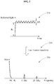
- FIG. 2 is a diagram illustrating a frequency domain signal according to an example embodiment.
- the detector 120 may detect a periodical change in a signal of interest.
- the controller 130 may extract R 0 + ⁇ R DC and ⁇ R f when filtering a frequency domain signal.
- the controller 130 may calculate a relative amount of change in reflectivity of a sample using a signal having been converted into a frequency domain.
- the controller 130 may convert the signal of interest into the frequency domain signal. Specifically, the controller 130 may restore an amount of change in intensity of the signal of interest detected by the detector 120, to be a digital signal using a digitizer. The controller 130 may convert the digital signal into a frequency domain signal 230 through a fast Fourier transform 220.
- the frequency domain signal may be an amount of change in intensity of a signal of interest as a function of a frequency, for example, an amount of change in reflectivity of a sample.
- the controller 130 may filter the frequency domain signal.
- the controller 130 may extract a frequency component corresponding to a frequency of the bias signal 151 and a DC component from the frequency domain signal.
- the controller 130 may calculate a relative amount of change in reflectivity of the sample 115 from the extracted DC component and frequency component. For example, the controller 130 may extract R 0 + ⁇ R DC and ⁇ R f when filtering the frequency domain signal.
- the controller 130 may calculate the relative amount of change in reflectivity using an equation of ⁇ R f /(R 0 + ⁇ R DC ), R 0 + ⁇ R DC being the extracted DC component, ⁇ R DC being an amount of change in reflectivity at a DC, and ⁇ R f being the extracted frequency component.
- the controller 130 may calculate the relative amount of change in reflectivity using an equation of ⁇ R f /R 0 , R 0 being a reflectivity of the sample 115 to which the bias signal 151 is not applied to the sample and ⁇ R f being the extracted frequency component.
- Equation 3 when a thermoreflectance coefficient is significantly small, ⁇ R may be smaller than R and thus, R may be substantially equal to Ro. Also, since ⁇ R DC included in the DC component is significantly small, a DC component value may be approximately equal to Ro. Ro may be the extracted DC component.
- the controller 130 may acquire a thermal image of the sample 115 based on the relative amount of change in reflectivity.
- a value of each pixel in the thermal image may correspond to the relative amount of change in reflectivity.
- the thermal image of the sample may be acquired.
- the collector 110 may scan the region of interest of the sample 115 based on a first control signal indicating a start and an end of an image and a second control signal indicating a start and an end of a row or a column of the image.
- the image may not have a pixel value.
- the pixel value of the image may be a calculated relative amount of change in reflectivity.
- the controller 130 may transmit a control signal 132 to the galvanometer scanner 111 included in the collector 110 so as to be used for scanning.
- the controller 130 may calculate the relative amount of change in reflectivity of each pixel in the image based on values sampled during the pixel unit time of the corresponding pixel. Also, the controller 130 may acquire the thermal image by two-dimensionally arranging the pixel value based on the first control signal and the second control signal.
- the controller 130 may sample the signal of interest at intervals of the pixel unit time. Also, the controller 130 may two-dimensionally arrange a reflectivity corresponding to the sampled signal of interest based on the first control signal and the second control signal, and acquire a plurality of reflection images. The controller 130 may calculate the relative amount of change in reflectivity based on a reflectivity corresponding to a pixel in the same location in the plurality of reflection images.
- a temperature distribution measuring apparatus may obtain a thermoreflectance coefficient based on the relative amount of change in reflectivity and a thermoreflectance coefficient measurement method. Also, the temperature distribution measuring apparatus may acquire a temperature distribution image of the sample 115 by applying the thermoreflectance coefficient to the thermal image. Here, the acquired temperature distribution image may be a temperature distribution image of a surface of the sample 115.
- FIG. 3 is a diagram illustrating a temperature distribution measuring apparatus that applies a high-frequency bias signal or a low-frequency bias signal to a sample to acquire a thermal image of the sample according to an example embodiment.
- a temperature distribution measuring apparatus 300 may include a bias signal applier 310, a scanner 320, a detector 330, and a controller 340.
- the bias signal applier 310 may apply a bias signal to a sample for a change in reflectivity of a signal reflected from the sample.
- the scanner 320 may scan the sample based on a first control signal indicating a start and an end of an image and a second control signal indicating a start and an end of a row or a column of the image.
- the detector 330 may detect, from the reflection signal, a signal of interest reflected from a region of interest of the sample.
- the detector 330 may use a pinhole to detect the signal of interest.
- the controller 340 may convert the signal of interest into a frequency domain signal and filter the frequency domain signal. Also, the controller 340 may extract a frequency component of the bias signal and a DC component from the frequency domain signal through the filtering. For example, the controller 340 may filter a signal having the same band of a frequency as that of frequencies of the DC component and the bias signal. The controller 340 may calculate a relative amount of change in reflectivity of the sample using the filtered DC component and a signal having a frequency component the same as the frequency of the bias signal. The controller 340 may calculate the relative amount of change in reflectivity using an equation of ⁇ R f /R 0 , Ro being the DC component included in the frequency domain signal and ⁇ R f being the frequency component of the bias signal included in the frequency domain signal. The controller 340 may determine a pixel value of an image to be the relative amount of change and acquire a thermal image of the sample.
- the temperature distribution measuring apparatus 300 may include a low-speed non-resonant galvanometer scanner and a high-speed digitizer. Related descriptions will be provided with reference to FIG. 4 .
- FIGS. 4A and 4B are diagrams illustrating a method of processing a frequency domain signal when a high-frequency bias signal is used according to an example embodiment.
- the bias signal may be a high-frequency bias signal.
- a signal output from a light detector of a temperature distribution measuring apparatus may include a reflected-light-intensity-change signal corresponding to at least one period per pixel unit time.
- the temperature distribution measuring apparatus may restore the reflected-light-intensity-change signal using a digitizer.
- a restored signal may be filtered to obtain a desired frequency component value after a fast Fourier transform.
- the temperature distribution measuring apparatus may include a low-speed non-resonant galvanometer scanner to readily satisfy a relatively long pixel unit time of the image and a high-speed digitizer to sufficiently sample a fast change in intensity of a reflected light.
- the temperature distribution measuring apparatus may induce a periodical change in reflectivity of a signal of interest or a reflection signal in a region of interest of a sample by applying a bias signal having a predetermined frequency f to the sample.
- the frequency of the bias signal may need to be sufficiently high such that numerous, for example, at least 10 bias signals are applied during a period of time corresponding to a single pixel of the image.
- a galvanometer scanner of the temperature distribution measuring apparatus may perform a raster scanning on the region of interest of the sample based on a control signal indicating a start and an end of the image and a control signal indicating a start and an end of each line of the image.
- the temperature distribution measuring apparatus may allow only a signal of interest reflected from the region of interest to pass a pinhole.
- the temperature distribution measuring apparatus may use the light detector to detect a reflected-light signal, for example, the signal of interest of which an intensity is changed periodically.
- the temperature distribution measuring apparatus may use a digitizer to sample an analog output signal of the light detector which is quickly changed during the pixel unit time of the image.
- the temperature distribution measuring apparatus may restore, to be a digital signal, the reflected-light signal that is periodically changed based on the bias signal applied during the pixel unit time.
- the temperature distribution measuring apparatus may obtain a frequency(f) component value of a bias signal and a DC component value in Fourier domain(frequency domain) after fast Fourier transform.
- the temperature distribution measuring apparatus may calculate a relative amount of change in reflectivity for each pixel unit time.
- the temperature distribution measuring apparatus may apply the calculated relative amount of change in reflectivity to a pixel value of an image.
- the temperature distribution measuring apparatus may acquire a thermal distribution image by two-dimensionally arranging each pixel value based on the control signals associated with the image and the line of the image.
- the temperature distribution measuring apparatus may measure a relative amount of change in intensity of the reflected light according to an increase in temperature of the sample.
- the temperature distribution measuring apparatus may obtain a thermoreflectance coefficient based on the measured relative amount of change and a thermoreflectance coefficient measurement method.
- the temperature distribution measuring apparatus may acquire a temperature distribution image of the sample by applying the thermoreflectance coefficient to the thermal distribution image.
- the temperature distribution measuring apparatus may include a high-speed resonant galvanometer scanner and a low-speed digitizer. Related descriptions will be provided with reference to FIGS. 5A through 5C .
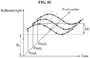
- FIGS. 5A through 5C are diagrams illustrating a method of processing a frequency domain signal when a low-frequency bias signal is used according to an example embodiment.
- the bias signal may be a low-frequency bias signal.
- a time of acquiring a thermal image of a sample may be prolonged.
- a temperature distribution measuring apparatus may include a high-speed resonant galvanometer scanner that reduces the pixel unit time of the image to quickly acquire the image.
- the temperature distribution measuring apparatus may include a low-digitizer to sample a slow change in intensity of a reflected light.
- a controller of the temperature distribution measuring apparatus may sample an output signal of a light detector for each pixel unit time of the image to continuously acquire a reflection image.
- the controller may arrange pixel values in the same location of all acquired reflection images to restore a reflected-light signal changing periodically.
- the controller may obtain a desired frequency component through filtering after a fast Fourier transform.
- a bias signal applier of the temperature distribution measuring apparatus may apply a bias signal of a predetermined frequency f to the sample.
- the temperature distribution measuring apparatus may induce a periodical change in reflectivity in a region of interest of the sample.
- the frequency of the bias signal may be less than a speed of acquiring a single image.
- a galvanometer scanner of the temperature distribution measuring apparatus may perform a raster scanning on the region of interest of the sample based on a control signal indicating a start and an end of the image and a control signal indicating a start and an end of each line of the image.
- the temperature distribution measuring apparatus may allow only a signal of interest reflected from the region of interest to pass a pinhole.
- the temperature distribution measuring apparatus may use the light detector to detect a reflected-light signal, for example, the signal of interest of which an intensity is changed periodically.
- the temperature distribution measuring apparatus may use a digitizer to sample an analog output signal of the light detector for each pixel unit time of the image.
- the temperature distribution measuring apparatus may restore a reflected-light intensity value for a predetermined instance.
- the temperature distribution measuring apparatus may two-dimensionally arrange the restored reflected-light intensity value into each pixel based on the control signals associated with the image and the line.
- the temperature distribution measuring apparatus may acquire a single reflection image through the two-dimensional arranging.
- the temperature distribution measuring apparatus may acquire a plurality of reflection images by repetitively performing an operation of sampling, restoring, and two-dimensionally arranging.
- values of pixels in the same location in reflection images acquired continuously may be the same as a value restored by sampling a reflected-light signal periodically changing at a location of the sample corresponding to the location of the pixel at an image acquiring speed using the digitizer.
- the temperature distribution measuring apparatus may perform the fast Fourier transform on the values of the pixels in the same location.
- the temperature distribution measuring apparatus may extract a DC component value and a frequency(f) component value in the transformed signal.
- the temperature distribution measuring apparatus may calculate a relative amount of change in reflectivity of the sample using an extracted value for each of the pixels in the same location, and apply the calculated relative amount of change in reflectivity of the sample to a value of the corresponding pixel in the image.
- the temperature distribution measuring apparatus may acquire a thermal distribution image of the sample by two-dimensionally arranging the pixel values based on the control signals associated with the image and the line.
- the temperature distribution measuring apparatus may measure a relative amount of change in intensity of the reflected light according to an increase in temperature of the sample.
- the temperature distribution measuring apparatus may obtain a thermoreflectance coefficient based on the measured relative amount of change and a thermoreflectance coefficient measurement method.
- the temperature distribution measuring apparatus may acquire a temperature distribution image of the sample by applying the thermoreflectance coefficient to the thermal distribution image.
- the temperature distribution measuring apparatus may obtain a thermoreflectance coefficient using the relative amount of change in reflectivity based on the thermoreflectance coefficient measurement method. Also, the temperature distribution measuring apparatus may acquire a temperature distribution image of the sample by applying the thermoreflectance coefficient to the thermal image.
- the acquired temperature distribution image may be a temperature distribution image of a surface of the sample.
- FIG. 6 is a flowchart illustrating a method of measuring a temperature distribution according to an example embodiment. The method of measuring a temperature distribution may be performed by a temperature distribution measuring apparatus.
- the temperature distribution measuring apparatus may collect a reflection signal having a reflectivity varying based on a bias signal applied to a sample.
- the temperature distribution measuring apparatus may detect, from the reflection signal, a signal of interest reflected from a region of interest of the sample.
- the temperature distribution measuring apparatus may convert the signal of interest into a frequency domain signal.
- the temperature distribution measuring apparatus may filter the frequency domain signal.
- the temperature distribution measuring apparatus may extract a frequency component of the bias signal and a DC component from the filtered frequency domain signal.
- the temperature distribution measuring apparatus may extract a frequency component ⁇ R f of a bias signal and a DC component R 0 + ⁇ R DC when filtering the frequency domain signal.
- the temperature distribution measuring apparatus may calculate a relative amount of change in reflectivity of the sample using the extracted frequency component and DC component.
- the temperature distribution measuring apparatus may calculate the relative amount of change in reflectivity using an equation of ⁇ R f /(R 0 + ⁇ R DC ), ⁇ R DC being an amount of change in reflectivity at a DC.
- the temperature distribution measuring apparatus may calculate the relative amount of change in reflectivity using an equation of ⁇ R f /R 0 , Ro being a reflectivity of the sample to which the bias signal 151 is not applied to the sample and ⁇ R f being the extracted frequency component.
- ⁇ R may be smaller than R and thus, R may be substantially equal to Ro.
- ⁇ R DC included in the DC component is significantly small, a DC component value may be approximately equal to Ro.
- Ro may be the extracted DC component.
- the temperature distribution measuring apparatus may acquire a thermal image of the sample based on the relative amount of change in reflectivity.
- a value of each pixel in the thermal image may correspond to the relative amount of change in reflectivity.
- the thermal image of the sample may be acquired.
- the temperature distribution measuring apparatus may scan the region of interest of the sample 115 based on based on a first control signal indicating a start and an end of an image and a second control signal indicating a start and an end of a row or a column of the image.
- the temperature distribution measuring apparatus may the relative amount of change in reflectivity of each pixel in the image as a pixel value of the corresponding pixel. Also, the temperature distribution measuring apparatus may acquire the thermal image by two-dimensionally arranging the pixel value based on the first control signal and the second control signal.
- the temperature distribution measuring apparatus may sample the signal of interest at intervals of the pixel unit time. Also, the temperature distribution measuring apparatus may two-dimensionally arrange a reflectivity corresponding to the sampled signal of interest based on the first control signal and the second control signal, and acquire a plurality of reflection images. The temperature distribution measuring apparatus may calculate the relative amount of change in reflectivity based on a reflectivity corresponding to a pixel in the same location in the plurality of reflection images.
- the temperature distribution measuring apparatus may obtain the thermoreflectance coefficient based on the relative amount of change in reflectivity and a thermoreflectance coefficient measurement method. Also, the temperature distribution measuring apparatus may acquire a temperature distribution image of the sample by applying the thermoreflectance coefficient to the thermal image.
- the acquired temperature distribution image may be a temperature distribution image of a surface of the sample.
- the units described herein may be implemented using hardware components and software components.
- the hardware components may include microphones, amplifiers, band-pass filters, audio to digital convertors, and processing devices.
- a processing device may be implemented using one or more general-purpose or special purpose computers, such as, for example, a processor, a controller and an arithmetic logic unit, a digital signal processor, a microcomputer, a field programmable array, a programmable logic unit, a microprocessor or any other device capable of responding to and executing instructions in a defined manner.
- the processing device may run an operating system (OS) and one or more software applications that run on the OS.
- the processing device also may access, store, manipulate, process, and create data in response to execution of the software.
- OS operating system
- a processing device may include multiple processing elements and multiple types of processing elements.
- a processing device may include multiple processors or a processor and a controller.
- different processing configurations are possible, such a parallel processors.
- the software may include a computer program, a piece of code, an instruction, or some combination thereof, for independently or collectively instructing or configuring the processing device to operate as desired.
- Software and data may be embodied permanently or temporarily in any type of machine, component, physical or virtual equipment, computer storage medium or device, or in a propagated signal wave capable of providing instructions or data to or being interpreted by the processing device.
- the software also may be distributed over network coupled computer systems so that the software is stored and executed in a distributed fashion.
- the software and data may be stored by one or more computer readable recording mediums.
- the methods according to the above-described embodiments may be recorded, stored, or fixed in one or more non-transitory computer-readable media that includes program instructions to be implemented by a computer to cause a processor to execute or perform the program instructions.
- the media may also include, alone or in combination with the program instructions, data files, data structures, and the like.
- the program instructions recorded on the media may be those specially designed and constructed, or they may be of the kind well-known and available to those having skill in the computer software arts.
- non-transitory computer-readable media examples include magnetic media such as hard disks, floppy disks, and magnetic tape; optical media such as CD ROM discs and DVDs; magneto-optical media such as optical discs; and hardware devices that are specially configured to store and perform program instructions, such as read-only memory (ROM), random access memory (RAM), flash memory, and the like.
- program instructions include both machine code, such as produced by a compiler, and files containing higher level code that may be executed by the computer using an interpreter.
- the described hardware devices may be configured to act as one or more software modules in order to perform the operations and methods described above, or vice versa.
Landscapes
- Physics & Mathematics (AREA)
- General Physics & Mathematics (AREA)
- Spectroscopy & Molecular Physics (AREA)
- Engineering & Computer Science (AREA)
- Multimedia (AREA)
- Signal Processing (AREA)
- Radiation Pyrometers (AREA)
- Measuring Temperature Or Quantity Of Heat (AREA)
- Testing Or Measuring Of Semiconductors Or The Like (AREA)
Applications Claiming Priority (2)
| Application Number | Priority Date | Filing Date | Title |
|---|---|---|---|
| KR1020140116811A KR101555153B1 (ko) | 2014-09-03 | 2014-09-03 | 온도 분포 측정 장치 및 방법 |
| PCT/KR2015/008795 WO2016036038A1 (ko) | 2014-09-03 | 2015-08-24 | 온도 분포 측정 장치 및 방법 |
Publications (3)
| Publication Number | Publication Date |
|---|---|
| EP3190395A1 true EP3190395A1 (de) | 2017-07-12 |
| EP3190395A4 EP3190395A4 (de) | 2018-04-25 |
| EP3190395B1 EP3190395B1 (de) | 2020-04-22 |
Family
ID=54345206
Family Applications (1)
| Application Number | Title | Priority Date | Filing Date |
|---|---|---|---|
| EP15839017.9A Active EP3190395B1 (de) | 2014-09-03 | 2015-08-24 | Vorrichtung und verfahren zur messung einer temperaturverteilung |
Country Status (5)
| Country | Link |
|---|---|
| US (1) | US10139284B2 (de) |
| EP (1) | EP3190395B1 (de) |
| JP (1) | JP6370997B2 (de) |
| KR (1) | KR101555153B1 (de) |
| WO (1) | WO2016036038A1 (de) |
Families Citing this family (11)
| Publication number | Priority date | Publication date | Assignee | Title |
|---|---|---|---|---|
| KR101555153B1 (ko) * | 2014-09-03 | 2015-10-06 | 한국기초과학지원연구원 | 온도 분포 측정 장치 및 방법 |
| US10180359B2 (en) * | 2017-01-29 | 2019-01-15 | Microsanj, LLC | Method and system for calibrating thermal imaging systems |
| JP6933613B2 (ja) * | 2017-08-10 | 2021-09-08 | Jfeテクノリサーチ株式会社 | 温度分布計測装置及び温度分布計測方法 |
| WO2019172386A1 (ja) * | 2018-03-08 | 2019-09-12 | Jfeテクノリサーチ株式会社 | 温度分布計測装置、温度分布計測方法、流体の流れ計測装置及びガス検知装置 |
| KR101938110B1 (ko) | 2018-06-05 | 2019-04-11 | 한국기초과학지원연구원 | 다중 모드 열영상 측정 장치 및 이의 동작 방법 |
| JP7065060B2 (ja) * | 2018-08-20 | 2022-05-11 | Jfeテクノリサーチ株式会社 | 流体の流れ計測装置及びガス検知装置 |
| KR102074593B1 (ko) * | 2018-11-09 | 2020-02-06 | 한국기초과학지원연구원 | 레이저 스캐닝 기반 현미경 장치 및 이의 동작 방법 |
| KR102088116B1 (ko) * | 2018-11-12 | 2020-03-11 | 한국기초과학지원연구원 | 열전달 모델 예측 기법 기반의 전자 현미경 및 그 제어 방법 |
| KR102331174B1 (ko) * | 2020-03-31 | 2021-11-26 | 주식회사 에프에스 | 화재발생 예측 시스템 및 그 방법 |
| CN113624358B (zh) * | 2021-07-14 | 2023-09-26 | 中国电子科技集团公司第十三研究所 | 用于光热反射显微热成像的三维位移补偿方法及控制装置 |
| KR102528823B1 (ko) * | 2021-11-18 | 2023-05-04 | 한국기초과학지원연구원 | 시분해 열영상 측정 장치 및 방법 |
Family Cites Families (13)
| Publication number | Priority date | Publication date | Assignee | Title |
|---|---|---|---|---|
| JPS63234127A (ja) | 1987-03-23 | 1988-09-29 | Chino Corp | 光学式温度測定装置 |
| US5612538A (en) | 1995-01-17 | 1997-03-18 | The Regents Of The University Of California | Faraday imaging at high temperatures |
| US7173245B2 (en) | 2001-01-04 | 2007-02-06 | The Regents Of The University Of California | Submicron thermal imaging method and enhanced resolution (super-resolved) AC-coupled imaging for thermal inspection of integrated circuits |
| US8362431B2 (en) * | 2005-03-15 | 2013-01-29 | Mount Holyoke College | Methods of thermoreflectance thermography |
| JP2006308513A (ja) | 2005-05-02 | 2006-11-09 | Nec Electronics Corp | 検査装置及び方法 |
| EP1738683A1 (de) * | 2005-06-30 | 2007-01-03 | Pixartis SA | Rekonstruktion von Mikrowellen-Temperaturbildern |
| KR101114362B1 (ko) * | 2009-03-09 | 2012-02-14 | 주식회사 쓰리비 시스템 | 결점검사를 위한 검사장치 |
| KR101080376B1 (ko) * | 2009-04-30 | 2011-11-04 | 광주과학기술원 | 간섭계를 이용한 이미지 생성 시스템 및 방법 |
| JP5575600B2 (ja) | 2010-09-30 | 2014-08-20 | 東京エレクトロン株式会社 | 温度測定方法、記憶媒体、プログラム |
| KR101350976B1 (ko) | 2010-12-22 | 2014-01-14 | 한국기초과학지원연구원 | 온도분포 측정장치 |
| KR101377655B1 (ko) | 2012-08-24 | 2014-03-24 | 한국기초과학지원연구원 | 적외선 이미지 센서의 발열 분포 측정장치 |
| KR101336946B1 (ko) * | 2012-11-27 | 2013-12-04 | 한국기초과학지원연구원 | 발열 분포 측정을 이용한 불량 분석 장치 및 방법 |
| KR101555153B1 (ko) * | 2014-09-03 | 2015-10-06 | 한국기초과학지원연구원 | 온도 분포 측정 장치 및 방법 |
-
2014
- 2014-09-03 KR KR1020140116811A patent/KR101555153B1/ko active Active
-
2015
- 2015-08-24 WO PCT/KR2015/008795 patent/WO2016036038A1/ko not_active Ceased
- 2015-08-24 EP EP15839017.9A patent/EP3190395B1/de active Active
- 2015-08-24 JP JP2017512972A patent/JP6370997B2/ja active Active
- 2015-08-24 US US15/508,357 patent/US10139284B2/en active Active
Also Published As
| Publication number | Publication date |
|---|---|
| JP6370997B2 (ja) | 2018-08-08 |
| WO2016036038A1 (ko) | 2016-03-10 |
| EP3190395A4 (de) | 2018-04-25 |
| US20170299440A1 (en) | 2017-10-19 |
| US10139284B2 (en) | 2018-11-27 |
| EP3190395B1 (de) | 2020-04-22 |
| JP2017534842A (ja) | 2017-11-24 |
| KR101555153B1 (ko) | 2015-10-06 |
Similar Documents
| Publication | Publication Date | Title |
|---|---|---|
| EP3190395B1 (de) | Vorrichtung und verfahren zur messung einer temperaturverteilung | |
| US10533895B2 (en) | Apparatus, systems, and methods for Talbot spectrometers | |
| US7336353B2 (en) | Coding and modulation for hyperspectral imaging | |
| US20180084195A1 (en) | System and method for automated extraction of high resolution structural dynamics from video | |
| EP4147194B1 (de) | Hintergrundkorrektur für doppelbrechungsmessungen | |
| JP2012519919A5 (de) | ||
| JP2020529602A (ja) | 符号化開口スペクトル画像解析装置 | |
| CN111344533A (zh) | 用于检测光的装置、系统和方法 | |
| EP3505886A2 (de) | Verfahren und vorrichtung zur umwandlung von gleichmässig oder ungleichmässig abgetasteten interferogrammen zur herstellung von spektraldaten | |
| O’holleran et al. | Methodology for imaging the 3D structure of singularities in scalar and vector optical fields | |
| JP6968895B2 (ja) | 電磁場の波頭の断層撮影分布を取得する方法及び光学システム | |
| KR101762384B1 (ko) | 이차원 물질의 도메인 구조 측정 시스템 및 그 방법 | |
| Michel et al. | Measurement of the defect size by shearography or other interferometric techniques | |
| JP7289643B2 (ja) | 不均一なリターダンス間隔での経路遅延の液晶可変リターダを通じた測定 | |
| Giakos et al. | Polarimetric wavelet fractal remote sensing principles for space materials | |
| JP2009019893A (ja) | センシング方法及びセンシング装置 | |
| Klein | Multispectral imaging and image processing | |
| Mikelsons et al. | A fast and robust implementation of the adaptive destriping algorithm for SNPP VIIRS and Terra/Aqua MODIS SST | |
| Barnard et al. | Accuracy and uncertainty in random speckle modulation transfer function measurement of infrared focal plane arrays | |
| WO2019022899A1 (en) | SYSTEM AND METHOD FOR IMAGE PROCESSING AND CHARACTERISTIC RECOGNITION | |
| Wei et al. | Phase-correction algorithm of deformed grating images in the depth measurement of weld pool surface in gas tungsten arc welding | |
| Chesebrough et al. | Light field imaging of three-dimensional structural dynamics | |
| Banerjee et al. | An optimized transport-of-intensity solution for phase imaging | |
| JP7406695B2 (ja) | 画像処理装置及び画像処理プログラム | |
| Li et al. | Spatio-temporal phase retrieval in speckle interferometry with Hilbert transform and two-dimensional phase unwrapping |
Legal Events
| Date | Code | Title | Description |
|---|---|---|---|
| STAA | Information on the status of an ep patent application or granted ep patent |
Free format text: STATUS: THE INTERNATIONAL PUBLICATION HAS BEEN MADE |
|
| PUAI | Public reference made under article 153(3) epc to a published international application that has entered the european phase |
Free format text: ORIGINAL CODE: 0009012 |
|
| STAA | Information on the status of an ep patent application or granted ep patent |
Free format text: STATUS: REQUEST FOR EXAMINATION WAS MADE |
|
| 17P | Request for examination filed |
Effective date: 20170303 |
|
| AK | Designated contracting states |
Kind code of ref document: A1 Designated state(s): AL AT BE BG CH CY CZ DE DK EE ES FI FR GB GR HR HU IE IS IT LI LT LU LV MC MK MT NL NO PL PT RO RS SE SI SK SM TR |
|
| AX | Request for extension of the european patent |
Extension state: BA ME |
|
| DAV | Request for validation of the european patent (deleted) | ||
| DAX | Request for extension of the european patent (deleted) | ||
| RIN1 | Information on inventor provided before grant (corrected) |
Inventor name: KIM, DONG UK Inventor name: CHANG, KI SOO |
|
| A4 | Supplementary search report drawn up and despatched |
Effective date: 20180322 |
|
| RIC1 | Information provided on ipc code assigned before grant |
Ipc: G01J 5/10 20060101AFI20180316BHEP |
|
| STAA | Information on the status of an ep patent application or granted ep patent |
Free format text: STATUS: EXAMINATION IS IN PROGRESS |
|
| 17Q | First examination report despatched |
Effective date: 20190403 |
|
| REG | Reference to a national code |
Ref country code: DE Ref legal event code: R079 Ref document number: 602015051350 Country of ref document: DE Free format text: PREVIOUS MAIN CLASS: G01J0005100000 Ipc: G01J0005000000 |
|
| RIC1 | Information provided on ipc code assigned before grant |
Ipc: G01J 5/00 20060101AFI20191101BHEP Ipc: G01K 11/12 20060101ALI20191101BHEP Ipc: G01J 5/10 20060101ALI20191101BHEP |
|
| GRAP | Despatch of communication of intention to grant a patent |
Free format text: ORIGINAL CODE: EPIDOSNIGR1 |
|
| STAA | Information on the status of an ep patent application or granted ep patent |
Free format text: STATUS: GRANT OF PATENT IS INTENDED |
|
| INTG | Intention to grant announced |
Effective date: 20191220 |
|
| GRAS | Grant fee paid |
Free format text: ORIGINAL CODE: EPIDOSNIGR3 |
|
| GRAA | (expected) grant |
Free format text: ORIGINAL CODE: 0009210 |
|
| STAA | Information on the status of an ep patent application or granted ep patent |
Free format text: STATUS: THE PATENT HAS BEEN GRANTED |
|
| AK | Designated contracting states |
Kind code of ref document: B1 Designated state(s): AL AT BE BG CH CY CZ DE DK EE ES FI FR GB GR HR HU IE IS IT LI LT LU LV MC MK MT NL NO PL PT RO RS SE SI SK SM TR |
|
| REG | Reference to a national code |
Ref country code: CH Ref legal event code: EP |
|
| REG | Reference to a national code |
Ref country code: DE Ref legal event code: R096 Ref document number: 602015051350 Country of ref document: DE |
|
| REG | Reference to a national code |
Ref country code: IE Ref legal event code: FG4D |
|
| REG | Reference to a national code |
Ref country code: AT Ref legal event code: REF Ref document number: 1260742 Country of ref document: AT Kind code of ref document: T Effective date: 20200515 |
|
| REG | Reference to a national code |
Ref country code: LT Ref legal event code: MG4D |
|
| REG | Reference to a national code |
Ref country code: NL Ref legal event code: MP Effective date: 20200422 |
|
| PG25 | Lapsed in a contracting state [announced via postgrant information from national office to epo] |
Ref country code: SE Free format text: LAPSE BECAUSE OF FAILURE TO SUBMIT A TRANSLATION OF THE DESCRIPTION OR TO PAY THE FEE WITHIN THE PRESCRIBED TIME-LIMIT Effective date: 20200422 Ref country code: NL Free format text: LAPSE BECAUSE OF FAILURE TO SUBMIT A TRANSLATION OF THE DESCRIPTION OR TO PAY THE FEE WITHIN THE PRESCRIBED TIME-LIMIT Effective date: 20200422 Ref country code: PT Free format text: LAPSE BECAUSE OF FAILURE TO SUBMIT A TRANSLATION OF THE DESCRIPTION OR TO PAY THE FEE WITHIN THE PRESCRIBED TIME-LIMIT Effective date: 20200824 Ref country code: NO Free format text: LAPSE BECAUSE OF FAILURE TO SUBMIT A TRANSLATION OF THE DESCRIPTION OR TO PAY THE FEE WITHIN THE PRESCRIBED TIME-LIMIT Effective date: 20200722 Ref country code: IS Free format text: LAPSE BECAUSE OF FAILURE TO SUBMIT A TRANSLATION OF THE DESCRIPTION OR TO PAY THE FEE WITHIN THE PRESCRIBED TIME-LIMIT Effective date: 20200822 Ref country code: FI Free format text: LAPSE BECAUSE OF FAILURE TO SUBMIT A TRANSLATION OF THE DESCRIPTION OR TO PAY THE FEE WITHIN THE PRESCRIBED TIME-LIMIT Effective date: 20200422 Ref country code: LT Free format text: LAPSE BECAUSE OF FAILURE TO SUBMIT A TRANSLATION OF THE DESCRIPTION OR TO PAY THE FEE WITHIN THE PRESCRIBED TIME-LIMIT Effective date: 20200422 Ref country code: GR Free format text: LAPSE BECAUSE OF FAILURE TO SUBMIT A TRANSLATION OF THE DESCRIPTION OR TO PAY THE FEE WITHIN THE PRESCRIBED TIME-LIMIT Effective date: 20200723 |
|
| REG | Reference to a national code |
Ref country code: AT Ref legal event code: MK05 Ref document number: 1260742 Country of ref document: AT Kind code of ref document: T Effective date: 20200422 |
|
| PG25 | Lapsed in a contracting state [announced via postgrant information from national office to epo] |
Ref country code: RS Free format text: LAPSE BECAUSE OF FAILURE TO SUBMIT A TRANSLATION OF THE DESCRIPTION OR TO PAY THE FEE WITHIN THE PRESCRIBED TIME-LIMIT Effective date: 20200422 Ref country code: BG Free format text: LAPSE BECAUSE OF FAILURE TO SUBMIT A TRANSLATION OF THE DESCRIPTION OR TO PAY THE FEE WITHIN THE PRESCRIBED TIME-LIMIT Effective date: 20200722 Ref country code: LV Free format text: LAPSE BECAUSE OF FAILURE TO SUBMIT A TRANSLATION OF THE DESCRIPTION OR TO PAY THE FEE WITHIN THE PRESCRIBED TIME-LIMIT Effective date: 20200422 Ref country code: HR Free format text: LAPSE BECAUSE OF FAILURE TO SUBMIT A TRANSLATION OF THE DESCRIPTION OR TO PAY THE FEE WITHIN THE PRESCRIBED TIME-LIMIT Effective date: 20200422 |
|
| PG25 | Lapsed in a contracting state [announced via postgrant information from national office to epo] |
Ref country code: AL Free format text: LAPSE BECAUSE OF FAILURE TO SUBMIT A TRANSLATION OF THE DESCRIPTION OR TO PAY THE FEE WITHIN THE PRESCRIBED TIME-LIMIT Effective date: 20200422 |
|
| REG | Reference to a national code |
Ref country code: DE Ref legal event code: R097 Ref document number: 602015051350 Country of ref document: DE |
|
| PG25 | Lapsed in a contracting state [announced via postgrant information from national office to epo] |
Ref country code: IT Free format text: LAPSE BECAUSE OF FAILURE TO SUBMIT A TRANSLATION OF THE DESCRIPTION OR TO PAY THE FEE WITHIN THE PRESCRIBED TIME-LIMIT Effective date: 20200422 Ref country code: RO Free format text: LAPSE BECAUSE OF FAILURE TO SUBMIT A TRANSLATION OF THE DESCRIPTION OR TO PAY THE FEE WITHIN THE PRESCRIBED TIME-LIMIT Effective date: 20200422 Ref country code: EE Free format text: LAPSE BECAUSE OF FAILURE TO SUBMIT A TRANSLATION OF THE DESCRIPTION OR TO PAY THE FEE WITHIN THE PRESCRIBED TIME-LIMIT Effective date: 20200422 Ref country code: CZ Free format text: LAPSE BECAUSE OF FAILURE TO SUBMIT A TRANSLATION OF THE DESCRIPTION OR TO PAY THE FEE WITHIN THE PRESCRIBED TIME-LIMIT Effective date: 20200422 Ref country code: SM Free format text: LAPSE BECAUSE OF FAILURE TO SUBMIT A TRANSLATION OF THE DESCRIPTION OR TO PAY THE FEE WITHIN THE PRESCRIBED TIME-LIMIT Effective date: 20200422 Ref country code: AT Free format text: LAPSE BECAUSE OF FAILURE TO SUBMIT A TRANSLATION OF THE DESCRIPTION OR TO PAY THE FEE WITHIN THE PRESCRIBED TIME-LIMIT Effective date: 20200422 Ref country code: DK Free format text: LAPSE BECAUSE OF FAILURE TO SUBMIT A TRANSLATION OF THE DESCRIPTION OR TO PAY THE FEE WITHIN THE PRESCRIBED TIME-LIMIT Effective date: 20200422 Ref country code: ES Free format text: LAPSE BECAUSE OF FAILURE TO SUBMIT A TRANSLATION OF THE DESCRIPTION OR TO PAY THE FEE WITHIN THE PRESCRIBED TIME-LIMIT Effective date: 20200422 |
|
| PG25 | Lapsed in a contracting state [announced via postgrant information from national office to epo] |
Ref country code: PL Free format text: LAPSE BECAUSE OF FAILURE TO SUBMIT A TRANSLATION OF THE DESCRIPTION OR TO PAY THE FEE WITHIN THE PRESCRIBED TIME-LIMIT Effective date: 20200422 Ref country code: SK Free format text: LAPSE BECAUSE OF FAILURE TO SUBMIT A TRANSLATION OF THE DESCRIPTION OR TO PAY THE FEE WITHIN THE PRESCRIBED TIME-LIMIT Effective date: 20200422 |
|
| PLBE | No opposition filed within time limit |
Free format text: ORIGINAL CODE: 0009261 |
|
| STAA | Information on the status of an ep patent application or granted ep patent |
Free format text: STATUS: NO OPPOSITION FILED WITHIN TIME LIMIT |
|
| 26N | No opposition filed |
Effective date: 20210125 |
|
| PG25 | Lapsed in a contracting state [announced via postgrant information from national office to epo] |
Ref country code: MC Free format text: LAPSE BECAUSE OF FAILURE TO SUBMIT A TRANSLATION OF THE DESCRIPTION OR TO PAY THE FEE WITHIN THE PRESCRIBED TIME-LIMIT Effective date: 20200422 |
|
| REG | Reference to a national code |
Ref country code: CH Ref legal event code: PL |
|
| GBPC | Gb: european patent ceased through non-payment of renewal fee |
Effective date: 20200824 |
|
| PG25 | Lapsed in a contracting state [announced via postgrant information from national office to epo] |
Ref country code: LU Free format text: LAPSE BECAUSE OF NON-PAYMENT OF DUE FEES Effective date: 20200824 Ref country code: LI Free format text: LAPSE BECAUSE OF NON-PAYMENT OF DUE FEES Effective date: 20200831 Ref country code: CH Free format text: LAPSE BECAUSE OF NON-PAYMENT OF DUE FEES Effective date: 20200831 |
|
| REG | Reference to a national code |
Ref country code: BE Ref legal event code: MM Effective date: 20200831 |
|
| PG25 | Lapsed in a contracting state [announced via postgrant information from national office to epo] |
Ref country code: SI Free format text: LAPSE BECAUSE OF FAILURE TO SUBMIT A TRANSLATION OF THE DESCRIPTION OR TO PAY THE FEE WITHIN THE PRESCRIBED TIME-LIMIT Effective date: 20200422 |
|
| PG25 | Lapsed in a contracting state [announced via postgrant information from national office to epo] |
Ref country code: BE Free format text: LAPSE BECAUSE OF NON-PAYMENT OF DUE FEES Effective date: 20200831 Ref country code: IE Free format text: LAPSE BECAUSE OF NON-PAYMENT OF DUE FEES Effective date: 20200824 Ref country code: GB Free format text: LAPSE BECAUSE OF NON-PAYMENT OF DUE FEES Effective date: 20200824 |
|
| PG25 | Lapsed in a contracting state [announced via postgrant information from national office to epo] |
Ref country code: TR Free format text: LAPSE BECAUSE OF FAILURE TO SUBMIT A TRANSLATION OF THE DESCRIPTION OR TO PAY THE FEE WITHIN THE PRESCRIBED TIME-LIMIT Effective date: 20200422 Ref country code: MT Free format text: LAPSE BECAUSE OF FAILURE TO SUBMIT A TRANSLATION OF THE DESCRIPTION OR TO PAY THE FEE WITHIN THE PRESCRIBED TIME-LIMIT Effective date: 20200422 Ref country code: CY Free format text: LAPSE BECAUSE OF FAILURE TO SUBMIT A TRANSLATION OF THE DESCRIPTION OR TO PAY THE FEE WITHIN THE PRESCRIBED TIME-LIMIT Effective date: 20200422 |
|
| PG25 | Lapsed in a contracting state [announced via postgrant information from national office to epo] |
Ref country code: MK Free format text: LAPSE BECAUSE OF FAILURE TO SUBMIT A TRANSLATION OF THE DESCRIPTION OR TO PAY THE FEE WITHIN THE PRESCRIBED TIME-LIMIT Effective date: 20200422 |
|
| PGFP | Annual fee paid to national office [announced via postgrant information from national office to epo] |
Ref country code: FR Payment date: 20250624 Year of fee payment: 11 |
|
| PGFP | Annual fee paid to national office [announced via postgrant information from national office to epo] |
Ref country code: DE Payment date: 20250624 Year of fee payment: 11 |