EP3190405B1 - Mesure de coefficient de dilatation thermique - Google Patents
Mesure de coefficient de dilatation thermique Download PDFInfo
- Publication number
- EP3190405B1 EP3190405B1 EP17152926.6A EP17152926A EP3190405B1 EP 3190405 B1 EP3190405 B1 EP 3190405B1 EP 17152926 A EP17152926 A EP 17152926A EP 3190405 B1 EP3190405 B1 EP 3190405B1
- Authority
- EP
- European Patent Office
- Prior art keywords
- measurement
- gauge
- temperature
- length
- sections
- Prior art date
- Legal status (The legal status is an assumption and is not a legal conclusion. Google has not performed a legal analysis and makes no representation as to the accuracy of the status listed.)
- Active
Links
Images


















Classifications
-
- G—PHYSICS
- G01—MEASURING; TESTING
- G01B—MEASURING LENGTH, THICKNESS OR SIMILAR LINEAR DIMENSIONS; MEASURING ANGLES; MEASURING AREAS; MEASURING IRREGULARITIES OF SURFACES OR CONTOURS
- G01B5/00—Measuring arrangements characterised by the use of mechanical techniques
- G01B5/004—Measuring arrangements characterised by the use of mechanical techniques for measuring coordinates of points
- G01B5/008—Measuring arrangements characterised by the use of mechanical techniques for measuring coordinates of points using coordinate measuring machines
-
- G—PHYSICS
- G01—MEASURING; TESTING
- G01N—INVESTIGATING OR ANALYSING MATERIALS BY DETERMINING THEIR CHEMICAL OR PHYSICAL PROPERTIES
- G01N25/00—Investigating or analyzing materials by the use of thermal means
- G01N25/16—Investigating or analyzing materials by the use of thermal means by investigating thermal coefficient of expansion
-
- G—PHYSICS
- G01—MEASURING; TESTING
- G01B—MEASURING LENGTH, THICKNESS OR SIMILAR LINEAR DIMENSIONS; MEASURING ANGLES; MEASURING AREAS; MEASURING IRREGULARITIES OF SURFACES OR CONTOURS
- G01B3/00—Measuring instruments characterised by the use of mechanical techniques
- G01B3/02—Rulers with scales or marks for direct reading
Definitions
- Dimension reference gauges are used in testing measuring devices such as coordinate measuring machines.
- Step gauges corresponding to a plurality of lengths as well as various gauge blocks whose end-to-end dimension is highly accurately calibrated are used for the dimension reference gauge.
- the step gauges are comb-shaped components having alternately arranged protrusions and recesses, where a plurality of reference dimensions are defined between end faces of the protrusions.
- the step gauges are produced by alternately arranging measurement blocks defining the protrusions and spacer blocks defining the recesses and fixing the arranged blocks on a holder.
- the step gauges are produced by cutting a single component into a form of the comb-shaped component.
- a calibration value of the end-to-end dimension of the step gauges is defined as a length at a specific temperature and is often defined as a length at 20 degrees C (industrial standard temperature).
- the measured length has to be converted to a length at a temperature during the calibration, which is usually referred to as a length temperature correction.
- a coefficient of thermal expansion (CTE) of the step gauge is accurately known.
- the CTE used for the temperature correction is written in a calibration certificate or a test certificate for most of the dimension reference gauges including step gauges. Such a CTE is indicated with tolerance.
- the tolerance is considered as a factor of uncertainty in determining uncertainty of the test. Accordingly, it is required that the CTE of the step gauge is highly accurately evaluated in order to reduce the uncertainty in the test.
- CTE of an object including a dimension reference gauge is obtained by changing the temperature of the object and measuring a length variation of the object due to the temperature change.
- the length L of the object is more than 10 5 times larger than the length variation ⁇ L. Accordingly, the accuracy of the value of the length L has relatively a small impact on the value of the CTE ⁇ .
- Patent Literature 1 JP-B-3897655 .
- Patent Literature 1 two pairs of optical interferometers opposed on a common measurement axis are used to highly accurately measure an end-to-end dimension of a measurement target (e.g. gauge block). Then, the temperature of the measurement target is changed using a temperature controller to measure the lengths at different temperature, thereby obtaining the thermal expansion due to the changed temperature to calculate the CTE.
- a measurement target e.g. gauge block
- optical interferometer requires a high cost for the optical interferometer.
- the optical interferometer per se is expensive, but also reflectivity of air has to be calculated in order to calibrate the wavelength of the measurement light, which entails measurement apparatuses for environment (e.g. temperature, humidity, atmospheric pressure and carbon dioxide concentration).
- environment e.g. temperature, humidity, atmospheric pressure and carbon dioxide concentration
- the measurable length is limited to the length of the measurement target. In other words, it is difficult to apply the above method in measurement of dimensions between protrusions at a middle portion of a reference gauge having comb-shaped measurement faces (e.g. a step gauge).
- Patent Literature 2 JP-A-2004-226369
- Patent Literature 3 JP-A-2005-83920
- Patent Literature 4 DE 10 2012 219 417 A1
- a step gauge (measurement target) is disposed in a temperature-controlled chamber. Further, a probe of an external coordinate measuring machine is introduced through an opening of the temperature-controlled chamber and the length of the step gauge is measured using the probe. Then, the temperature setting inside the temperature-controlled chamber is changed to measure the length at different temperature, and the thermal expansion is calculated based on the difference in the measurement lengths before and after changing the temperature.
- the length measurement using the coordinate measuring machine does not require an optical interferometer and can be performed as long as a general-purpose coordinate measuring machine is usable in the measurement environment.
- the dimensions between protrusions at the middle portion of the step gauge can be measured with the use of the coordinate measuring machine, so that uniformity of thermal expansivity at the middle portion can also be measured.
- a pinching unit configured to pinch desired one of protrusions of a step gauge and a strain gauge disposed on one of chips of the pinching unit in contact with the step gauge are used, where the temperature is changed while pinching a pair of end faces whose length is to be measured with the pinching unit to directly detect the thermal expansion due to the temperature change using the strain gauge.
- the above-described measurement for the CTE ⁇ of the dimension reference gauge is required to be usable for the high-accuracy measurement of the dimension reference gauge with a large length L.
- the measurable length is fixed by the pinching unit in the above-described method disclosed in Patent Literature 3 and it is not possible to measure a wide variety of lengths (e.g. length of the middle portion). Further, since a pinching unit of a correspondingly large size has to be prepared for a long step gauge, applicability of the method is limited.
- the output of the strain gauge contains noise components, it is difficult to extract only the CTE of the step gauge from the converted length.
- a coordinate measuring machine involves a maximum permissible length measurement error (an index of measurement performance of the coordinate measuring machine).
- the maximum permissible length measurement error is usually given in a form of a linear expression and becomes larger in proportion to the length to be measured, which means that the larger the length to be measured becomes, the lower the accuracy becomes.
- a CTE of a long step gauge is difficult to be measured with a high accuracy for the above reason.
- some of the dimension reference gauges (e.g. a step gauge) use a section length at a middle portion thereof as a reference length, in addition to the entire length (i.e. an end-to-end distance) thereof.
- the section length of the step gauge is defined between end faces of two of the linearly arranged plurality of protrusions at a middle portion.
- the CTE in the dimension reference gauge such as a step gauge usually refers to a value obtained by: dividing a thermal deformation over the entire length of the dimension reference gauge by the entire length; and further dividing the obtained deformation per length by a temperature variation before and after the thermal deformation, which is a sort of representative value.
- the CTE sometimes is not even over the entire length in an actual step gauge.
- a part of the step gauge in a drawing direction may have high or low CTE. Accordingly, when the section length of the middle portion as described above is defined, it is possible that the CTE of the section is not equal to the CTE (i.e. a representative value) and thus the accuracy of the section length at the middle portion as a dimension reference cannot be ensured.
- the dimension reference gauge such as a step gauge
- the above-described length measurement between the protrusions at the middle portion of the step gauge is of great importance.
- a reference gauge corresponding to a length to be measured in a temperature-controlled chamber it is necessary to house a reference gauge corresponding to a length to be measured in a temperature-controlled chamber together with a measurement target and to set an inside of the temperature-controlled chamber at a predetermined temperature condition.
- a multiple of intermediate section lengths are defined for the measurement target, corresponding number of reference gauges are required.
- complicated processes of exchanging the reference gauge in the temperature-controlled chamber and then setting the temperature-controlled chamber at a plurality of temperatures in order to measure each of the section lengths at the plurality of temperatures are required.
- the standard of the gauge block includes "JISB7506" and "ISO3650.”
- a gauge block having 0.5 mm or more and 1000 mm or less of the entire length is defined. Accordingly, the maximum length of the existing gauge block is 1000 mm. In order to measure a length exceeding the maximum length, it is necessary to prepare a dedicated gauge block with desired accuracy, or to use a plurality of the gauge blocks in combination.
- An object of the invention is to provide a coefficient-of-thermal-expansion (CTE) measurement method and a measuring device for coefficient of thermal expansion (CTE measuring device) capable of highly accurately and inexpensively measuring a CTE of dimension reference gauges of various lengths.
- CTE coefficient-of-thermal-expansion
- a CTE measurement method is for a measurement target in a form of a dimension reference gauge, the CTE being measured for a plurality of measurement sections defined by a plurality of pairs of a measurement start point and a measurement end point of the measurement target that are distanced in a drawing direction of the measurement target, the method including: providing: a reference gauge including a plurality of pairs of reference start points and reference end points that define a plurality of reference sections corresponding to the plurality of measurement sections, a length of each of the reference sections being known, and wherein at each of one or more positions, each of the one or more positions corresponding to a respective one of the measurement start points and the measurement end points of the measurement target, is an insert hole; a temperature-controlled chamber configured to adjust an interior temperature thereof and to house the measurement target and the reference gauge, the temperature-controlled chamber including a measurement surface provided with a measurement aperture; and a coordinate measuring machine including a measurement probe that is introducible into an inside of the temperature-controlled chamber through the measurement aperture, the measurement probe
- the positions of the measurement start point and the measurement end point can be detected by introducing the measurement probe through the insert hole.
- the CTE of each of the sections at the middle portion of the dimension reference gauge can be efficiently measured by calculating the CTE for each of the plurality of measurement sections based on the measured length at the first temperature and the measured length at the second temperature.
- the CTE of the dimension reference gauges of various lengths can be highly accurately measured without using an expensive optical interferometer.
- the lengths of the first to third measurement sections of the measurement target can be measured by sequentially performing relative measurements with respect to the first to third reference sections of the reference gauge at each of the first and second temperatures.
- the CTE of each of the measurement sections i.e. first to third CTEs can be obtained based on the difference in the lengths of the first to third measurement sections at the first temperature and the lengths of the first to third measurement sections at the second temperature, and the temperature difference between the first temperature and the second temperature.
- first to third measurement sections and the corresponding first to third reference sections may be defined so that the positions of the corresponding start and end points in the drawing direction (and consequently the lengths of the sections) are completely identical, the start and end points in the drawing direction may be at different positions to define different lengths for the measurement sections.
- the difference in the length between each of the corresponding measurement sections and the reference sections is preferably 10 mm or less.
- the numbers of the measurement sections and the reference sections are not limited to three (i.e. the first to third) but may be two (i.e. first and second) or more than three.
- the dimension reference gauge as the measurement target is exemplarily a step gauge.
- the plurality of measurement sections may be defined between start points and end points defined on surfaces of a plurality of protrusions arranged on the step gauge.
- the measurement target of the invention is not restricted to the step gauge but may alternatively be other dimension reference gauge that is configured to define a plurality of length references in a drawing direction.
- the substantive reference start point and reference end point can be defined on the surface of the protrusion formed on the reference gauge.
- the reference gauge having the protrusion is, for instance, a step gauge.
- the substantive reference start point and reference end point may be formed on both end faces of the reference gauge.
- the reference gauge is in a form of a combination of a plurality of gauge blocks corresponding to the reference sections, end faces of the gauge blocks defining the reference start points and the reference end points.
- the reference gauge can be constructed by combining the plurality of existing gauge blocks. Since the plurality of gauge blocks each define a reference section between a reference start point and a reference end point defined on each of the end faces of the gauge blocks, the reference sections of a plurality of lengths can be defined when the gauge blocks are combined. Thus, the reference gauge having the reference sections with the plurality of lengths can be easily and inexpensively produced.
- the plurality of gauge blocks are layered in a descending order of the entire length thereof.
- a shorter one of the gauge blocks fixed on the other (longer) one of the gauge blocks defines the above-described "protrusion formed on the reference gauge.”
- a member wrapping the combined gauge blocks, a member penetrating the gauge blocks or an adhesive for bonding the gauge blocks may be used.
- the reference start points of two or more of the plurality of gauge blocks may be coplanarly arranged so that the difference in the length of the gauge blocks may appear solely on an opposite end or, alternatively, the ends may be shifted with each other so that the difference in the length of the block gauges appears on both ends of the block gauge(s).
- a CTE measuring device is for a measurement target in a form of a dimension reference gauge, the CTE of the measurement target being measured for a plurality of measurement sections defined by a plurality of pairs of a measurement start point and a measurement end point of the measurement target that are distanced in a drawing direction of the measurement target, the CTE measuring device including: a reference gauge including a plurality of pairs of reference start points and reference end points that define a plurality of reference sections corresponding to the plurality of measurement sections, a length of each of the reference sections being known; a temperature-controlled chamber configured to adjust an interior temperature thereof and to house the measurement target and the reference gauge, the temperature-controlled chamber including a measurement surface provided with a measurement aperture; and a coordinate measuring machine including a measurement probe that is introducible into an inside of the temperature-controlled chamber through the measurement aperture; and is characterized in that at each of one or more positions, each of the one or more positions corresponding to a respective one of the measurement start points and the measurement end points of the measurement target,
- a CTE (Coefficient of Thermal Expansion) measuring device 1 measures a dimension reference gauge in a form of a step gauge 10 to highly accurately measure CTE of the step gauge 10.
- the coordinate measuring machine 40 includes a measurement table 41.
- a head 44 is supported above the measurement table 41 via a column 42 and a crossbar 43.
- a ram 45 extending downward is provided to the head 44.
- a probe 46 is supported at a distal end of the ram 45.
- the column 42 of the coordinate measuring machine 40 is movable in a Y-axis direction with respect to the measurement table 41.
- the head 44 is movable in an X-axis direction with respect to the crossbar 43.
- the ram 45 is movable in a Z-axis direction with respect to the head 44.
- the probe 46 is three-dimensionally movable with respect to the measurement table 41 using the three-axis movement.
- An upper face of the temperature-controlled chamber 30 is openable and closable so as to house the step gauge 10 and the reference gauge block 2 inside the temperature-controlled chamber 30.
- a plurality of measurement apertures 31 each having an openable and closable lid are provided on the upper face of the temperature-controlled chamber 30 in alignment in the Y-axis direction.
- the step gauge 10 is supported inside the temperature-controlled chamber 30 so that a drawing direction Lt of the step gauge 10 extends along the Y-axis direction.
- the reference gauge block 2 is disposed in a manner facing an upper side of the step gauge 10 (i.e. a side of the step gauge 10 oriented to face the measurement aperture 31) and is supported so that a drawing direction Lr of the reference gauge block 2 extends along the Y-axis direction (i.e. in parallel with the step gauge 10).
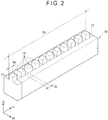
- the step gauge 10 (the measurement target) includes a square-column body extending in the drawing direction Lt.
- a top face, bottom face and lateral faces of the body are parallel to one of a vertical direction Ht and width direction Wt that intersect the drawing direction Lt.
- a plurality of protrusions 19 each in a form of a gauge block are provided on the upper face of the step gauge 10 in alignment in the drawing direction Lt.
- a length of each of the protrusions 19 in the drawing direction Lt is denoted by Dp.
- a dimension of a recess defined between opposing ones of the protrusions 19 in the drawing direction Lt is denoted by Dc.
- a surface of one of the protrusions 19 at a first end of the step gauge 10 is denoted by a first surface 11
- a surface of another one of the protrusions 19 at a second end of the step gauge 10 is denoted by a second surface 12 and a distance between the first surface 11 and the second surface 12 is measured as a length Dx of the step gauge 10.
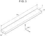
- the reference gauge block 2 (the reference gauge) is a gauge block extending in the drawing direction Lr.
- a top face, bottom face and lateral faces of the reference gauge block 2 are each parallel to one of a vertical direction Hr and width direction Wr that intersect the drawing direction Lr.
- a first reference surface 2A and a second reference surface 2B of the reference gauge block 2 are defined by a pair of end faces at both ends in the drawing direction Lr.
- a distance between the first reference surface 2A and the second reference surface 2B (i.e. a length) of the reference gauge block 2 is defined as Drx.
- the length Drx of the reference gauge block 2 is shorter than the to-be-measured length Dx (nominal dimension) of the step gauge 10 (i.e. the measurement target) by a predetermined dimension (e.g. a length Dp of one of the protrusions 19).
- the length Drx of the reference gauge block 2 is known but also the CTE of the reference gauge block 2 is highly accurately known. Accordingly, when the lengths are measured and compared at a later-described first temperature t1 and at a second temperature t2, the length Drx each of the temperatures t1, t2 can be highly accurately calculated based on the CTE.
- the step gauge 10 and the reference gauge block 2 are placed in the temperature-controlled chamber 30 in parallel with each other.
- a highly rigid bottom plate 32 is placed in the temperature-controlled chamber 30.
- a measurement target support base 50 and a reference gauge support base 60 are placed on an upper face of the bottom plate 32.
- the measurement target support base 50 includes a first measurement target support base 51 near the first surface 11 and a second measurement target support base 52 near the second surface 12.
- the reference gauge support base 60 includes a first reference gauge support base 61 near the first reference surface 2A and a second reference gauge support base 62 near the second reference surface 2B.
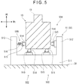
- the first measurement target support base 51 includes a base 511 placed on the bottom plate 32 and upright portions 512, 513 provided along side edges of the base 511.
- the step gauge 10 is received in a space between the upright portions 512, 513 and supported above the base 511.
- Each of the ball holders 515 includes a plurality of support balls that are configured to roll on each of the balls 514, thereby defining a so-called free ball bearing or ball caster.
- a bottom face of the step gauge 10 is in contact with the two balls 514.
- the balls 514 and the ball holders 515 define plane-sphere contact portions 502 between the first measurement target support base 51 and the bottom face of the step gauge 10.
- the load of the step gauge 10 are supported by the temperature-controlled chamber 30 through the two pairs of contact portions 502, the base 511 and the bottom plate 32.
- the step gauge 10 is displaceable in the drawing direction Lt and the width direction Wt and is capable of rotation around an axis in the vertical direction H and an axis in the width direction Wt (i.e. yawing and pitching).
- a ball 514 and a ball holder 515 similar to those of the contact portions 502 between the bottom face of the step gauge 10 and the base 511 are provided between the upright portion 512 and one of the lateral faces of the step gauge 10, thereby defining a plane-sphere contact portion 504.
- a ball 514 and a ball holder 515 similar to those of the contact portions 502 between the bottom face of the step gauge 10 and the base 511 are provided between the upright portion 513 and the other one of the lateral faces of the step gauge 10. Further, a compression coil spring 516 is provided between the ball holder 515 and the upright portion 513. The ball 514, the ball holder 515 and the compression coil spring 516 define a pressing unit 505.
- the first measurement target support base 51 supports the load of the step gauge 10 and restricts the displacement of the step gauge 10 along the vertical direction Ht using the two contact portions 502.
- the displacement of the step gauge 10 in the width direction Wt is also restricted by the contact portion 504 and the pressing unit 505, so that the orientation of the step gauge 10 in the drawing direction Lt is determined.
- the first measurement target support base 51 permits the displacement in the drawing direction Lt as well as pitching and yawing.
- the step gauge 10 is thermally deformed, extension and contraction in the drawing direction Lt are permitted.
- the second measurement target support base 52 includes a base 521 placed on the bottom plate 32 and support portion 522 on which the lower face of the step gauge 10 is placed.
- a ball 524 and a ball holder 525 are provided on the base 521.
- the ball holder 525 includes a plurality of support balls that are configured to roll on the ball 524, thereby defining a so-called free ball bearing or ball caster.
- the conical hole 529 and the ball 524 define a conical-hole-sphere contact portion 501.
- the second measurement target support base 52 restricts the displacement of the step gauge 10 in all of the vertical direction Ht, the width direction Wt and the drawing direction Lt using the contact portion 501 while supporting the load of the step gauge 10 at the contact portion 501.
- the contact portion 501 permits all of a rotation (yawing) around an axis passing through the ball 524 and extending in the vertical direction Ht, a rotation (pitching) around an axis passing through the ball 524 and extending in the width direction Wt and a rotation (rolling) around an axis passing through the ball 524 and extending in the drawing direction Lt.
- the step gauge 10 is supported by the first measurement target support base 51 and the second measurement target support base 52.
- the step gauge 10 is supported so that the position of the step gauge 10 in the width direction Wt is restricted by each of the first measurement target support base 51 and the second measurement target support base 52 and the drawing direction Lt of the step gauge 10 is aligned with the Y-axis direction of the temperature-controlled chamber 30 and the coordinate measuring machine 40.
- the displacement of the step gauge 10 in the drawing direction Lt is permitted by the first measurement target support base 51, so that the extension/contraction due to thermal deformation mainly appears on the side of the first surface 11.
- the first reference gauge support base 61 includes a base 611 disposed above the bottom plate 32 and a post 612 fixed to a lower face of the base 611.
- the first reference gauge support base 61 is supported by the bottom plate 32 via the post 612.
- the ball 614 of one of the two pairs of the balls 614 and ball holders 615 is in contact with a lower face of the reference gauge block 2 to define a plane-sphere contact portion 602.
- the ball 614 of the other one of the two pairs of the balls 614 and ball holders 615 is fitted in a conical hole 619 (see Fig. 9 ) formed on the lower face of the reference gauge block 2 to define a conical-hole-sphere contact portion 601.
- the first reference gauge support base 61 supports the load of the reference gauge block 2 through the plane-sphere contact portion 602 and the conical-hole-sphere contact portion 601 aligned in the width direction Wr, where the displacement in the vertical direction Hr, the displacement in the width direction Wr, the displacement in the drawing direction Lr and a rotation around an axis in the drawing direction Lr (rolling) are restricted and a rotation around an axis in the vertical direction Hr (yawing) and a rotation around an axis in the width direction Wr (pitching) are permitted.
- an upright portion 610 is formed on the base 611.
- a ball 614 and a ball holder 615 similar to those at the contact portion 602 and a compression coil spring 617 configured to bias the ball 614 and the ball holder 615 toward an upper face of the reference gauge block 2 are provided between the upright portion 610 and the upper face of the reference gauge block 2, which define a preloading unit 609 configured to preload the reference gauge block 2 downward.
- the preloading unit 609 of the first reference gauge support base 61 reliably maintains the contact of the contact portions 601, 602 with the lower face of the reference gauge block 2 even when the reference gauge block 2 is of a light weight.
- the second reference gauge support base 62 includes a base 621, a post 622 and an upright portion 620 similar to those of the first reference gauge support base 61.
- a similar preloading unit 609 is defined by a ball 624, a ball holder 625 and a compression coil spring 627.
- a V-groove-sphere contact portion 603 is defined in the second reference gauge support base 62 in place of the plane-sphere contact portion 602 and the conical-hole-sphere contact portion 601 in the first reference gauge support base 61.
- the ball 624 and the ball holder 625 are provided on an upper face of the base 621.
- a V-shaped groove 628 is formed on an opposing lower face of the reference gauge block 2 along the drawing direction Lr (see Fig. 9 ).
- the ball 624 is fitted in the V-shaped groove 628 to define a V-shaped-groove-sphere contact portion 603.
- the second reference gauge support base 62 supports the load of the reference gauge block 2 through the V-groove-sphere contact portion 603 and restricts the displacement in the vertical direction Hr and the displacement in the width direction Wr, whereas the displacement in the drawing direction Lr and the rotation around an axis in the drawing direction Lr (rolling), the rotation around an axis in the vertical direction Hr (yawing) and the rotation around an axis in the width direction Wr (pitching) are permitted.
- the reference gauge block 2 is supported by the first reference gauge support base 61 and the second reference gauge support base 62.
- the reference gauge block 2 is supported so that the position of the reference gauge block 10 in the width direction Wr is restricted by each of the first reference gauge support base 61 and the second reference gauge support base 62 and the drawing direction Lr of the reference gauge block 2 is aligned with the Y-axis direction of the temperature-controlled chamber 30 and the coordinate measuring machine 40 (i.e. the drawing direction Lt of the step gauge 10).
- Fig. 10 shows a process for measuring CTE of the step gauge 10 using the CTE measuring device 1.
- the CTE measuring device 1 is initially constructed by fixing the temperature-controlled chamber 30 on the coordinate measuring machine 40 and placing the step gauge 10 and the reference gauge block 2 inside the temperature-controlled chamber 30 (Step S1).
- the first measurement target support base 51 and the second measurement target support base 52 are initially placed to support the step gauge 10. Subsequently, the first reference gauge support base 61 and the second reference gauge support base 62 are placed to extend over the step gauge 10 to support the reference gauge block 2.
- the length Drx of the reference gauge block 2 is set to be shorter than the length Dx of the step gauge 10 by the length Dp of one of the protrusions 19, the first reference surface 2A does not reach the first surface 11 by the length Dp of one of the protrusions 19 but an upper face of the one of the protrusions 19 nearest the first surface 11 is left uncovered by the reference gauge block 2 when the second reference surface 2B and the second surface 12 are coplanar.
- Step S3 the temperature inside the temperature-controlled chamber 30 is set at the first temperature t1 and is kept for a predetermined time so that the temperature is stabilized.
- Step S4 When the temperature inside the temperature-controlled chamber 30 is stabilized at the first temperature t1, coordinate system of the step gauge 10 and the reference gauge block 2 are determined (Step S4).
- one of the measurement apertures 31 near the first surface 11 is opened and the probe 46 of the coordinate measuring machine 40 is introduced thereinto. Then, the probe 46 is brought into contact with three or more points on the first surface 11 of the step gauge 10 to detect the position and inclination of the first surface 11 as shown in Fig. 12 . Further, the probe 46 is brought into contact with three or more points on an upper face and one of lateral faces of the one of the protrusions 19 on which the first surface 11 is defined to detect the position and inclination thereof. Thus, three-dimensional coordinates of the center point of the first surface 11 and the orientation of the drawing direction Lt of the step gauge 10 are obtained.
- the probe 46 is brought into contact with the first reference surface 2A and adjacent upper face and one of lateral faces of the reference gauge block 2 to obtain the three-dimensional coordinates of the center point of the first reference surface 2A and the orientation of the reference gauge block 2 in the drawing direction Lr.
- the relative measurement of the distance between the first surface 11 and the second surface 12 i.e. an accurate value of the length Dx
- the relative measurement of the distance between the first surface 11 and the second surface 12 can be performed based on the distance between the first reference surface 2A and the second reference surface 2B (the length Drx of the reference gauge block 2) with reference to the distance between the center point of the first surface 11 and the center point of the first reference surface 2A, and the distance between the center point of the second surface 12 and the center point of the second reference surface 2B.
- Step S6 When the relative measurement of the distance between the first surface 11 and the second surface 12 at the first temperature t1 is completed, the temperature inside the temperature-controlled chamber 30 is changed to the second temperature t2 (Step S6), and the above-described relative measurement operations (Step S3 to S5) are repeated.
- the CTE of the step gauge 10 Since the length of the step gauge 10 (measurement target) is measured using the coordinate measuring machine 40, the CTE of the step gauge 10 having various lengths can be highly accurately measured without using an expensive optical interferometer.
- the coordinate system is determined (Step S4 in Fig. 11 ) including the calculation of the center coordinates of the first reference surface 2A, the second reference surface 2B, the first surface 11 and the second surface 12 and the calculation of the inclination of the reference gauge block 2 and the step gauge 10 with respect to the drawing directions Lr, Lt, when the relative measurement is performed.
- each of the reference gauge block 2 and the step gauge 10 is determined based on the current condition of the reference gauge block 2 and the step gauge 10 and the length measurement is performed under the coordinate system, the accuracy of the length measurement can be enhanced and, consequently, the accuracy of the relative measurement can be kept at a high level.
- the length Drx from the first reference surface 2A to the second reference surface 2B of the reference gauge block 2 is set to be shorter than the length Dx from the first surface 11 to the second surface 12 of the step gauge 10 by the length Dp of one of the protrusions 19.
- the probe 46 of the coordinate measuring machine 40 is brought into contact with the exposed surface in determining the coordinate system as described above, so that the surface of the step gauge 10 can be detected without causing any interference with the reference gauge block 2.
- the difference in the lengths of the reference gauge block 2 and the step gauge 10 is maximized at the end (i.e. the side at which the first surface 11 and the first reference surface 2A are defined) opposite the coplanar side when the reference gauge block 2 is set to be shorter than the step gauge 10 by the predetermined length, so that the margin for the surface detection using the probe 46 of the coordinate measuring machine 40 can be maximized.
- the reference gauge support base 60 includes the first reference gauge support base 61 and the second reference gauge support base 62, which define a three-point kinematic mount including the conical-hole-sphere contact portion 601, the plane-sphere contact portion 602 and the V-shaped-groove-sphere contact portion 603 in contact with the bottom face of the reference gauge block 2, so that the displacement and rotation in the drawing direction Lr and directions (vertical direction Hr, width direction Wr) intersecting the drawing direction Lt can be appropriately restricted.
- the first comparative example is applicable to a measurement of the step gauge 10 with shorter length or to a measurement of a length between the protrusions 19 at the middle portion of the step gauge 10.
- the first surface 11 is defined at one of the protrusions 19 at the middle portion as shown in dot-and-dash line
- the first reference surface 2A is defined using a reference gauge block 2 of a corresponding length and the first surface 11 and the first reference surface 2A may be measured using the probe 46.
- the nearest one of the plurality of measurement apertures 31 may be used when the probe 46 is introduced into the temperature-controlled chamber 30.
- Fig. 13 shows a second comparative example.
- the conical hole 619 and the V-shaped groove 628 are directly formed on the lower face of the reference gauge block 2 in order to support the reference gauge block 2 using the first reference gauge support base 61 and the second reference gauge support base 62.
- the support adapters 71, 72 are attached to the reference gauge block 2 in the second comparative example, the support adapter may be applied to the step gauge 10.
- the support adapter 71 is provided to the reference gauge block 2 at a position capable of being supported by the first reference gauge support base 61.
- the support adapter 71 includes a support plate 711 and a fixing member 712. The support plate 711 and the fixing member 712 hold therein the reference gauge block 2 so that the support adapter 71 is fixed to the reference gauge block 2.
- the support adapter 72 is provided to the reference gauge block 2 at a position capable of being supported by the second reference gauge support base 62.
- the support adapter 72 includes a support plate 721 and a fixing member 722. The support plate 721 and the fixing member 722 hold therein the reference gauge block 2 so that the support adapter 72 is fixed to the reference gauge block 2.
- a conical hole 619 is formed on a lower face of the support plate 711.
- a V-shaped groove 628 is formed on a lower face of the support plate 721.
- the conical-hole-sphere contact portion 601, the plane-sphere contact portion 602 and the V-shaped-groove-sphere contact portion 603 are defined between the support adapters 71, 72 and the first and second reference gauge support bases 61, 62 in a manner similar to the lower face of the reference gauge block 2 in the first comparative example (see Fig. 9 ).
- the advantages of the above-described first comparative example can be obtained without providing the conical hole 619 and the V-shaped groove 628 on the lower face of the reference gauge block 2.
- general-purpose reference gauge blocks 2 can be used by using the support adapters 71, 72 in common, whereby the reference gauge blocks 2 of various dimensions can be easily used.
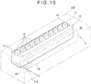
- Figs. 14 and 15 show a third comparative example of the invention.
- the measurement aperture 31 for introducing the probe 46 is provided on the upper face of the temperature-controlled chamber 30 and the protrusions 19 are provided to the upper face of the step gauge 10 (i.e. at the side facing the measurement apertures 31) and the reference gauge block 2 is provided in parallel to and above the step gauge 10 inside the temperature-controlled chamber 30.
- measurement apertures 31A into which the probe 46 is configured to be introduced are provided on one of lateral faces of the temperature-controlled chamber 30A, the step gauge 10 is disposed along the one of the lateral faces and the reference gauge block 2 is disposed between the one of the lateral faces and the step gauge 10 in parallel to each other.
- the third comparative example offers the same advantages as those mentioned in the above-described first comparative example.
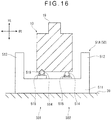
- Figs. 16 and 17 show a fourth comparative example.
- a first measurement target support base 51A (see Fig. 16 ) of the fourth comparative example includes a plane-sphere contact portion 502 and the conical-hole-sphere contact portion 501 (conical hole 519) abutting the lower face of the step gauge 10 and a second measurement target support base 52A (see Fig. 17 ) includes a V-shaped-groove-sphere contact portion 503 (V-shaped groove 528) abutting the lower face of the step gauge 10.
- an arrangement corresponding to the kinematic mount can be provided between the step gauge 10 and the first and second measurement target support bases 51A, 52A.
- conical-hole-sphere contact portion 501 may be provided between the first measurement target support base 51A and the step gauge 10 and the plane-sphere contact portion 502 and the V-shaped-groove-sphere contact portion 503 may be provided between the second measurement target support base 52A and the step gauge 10.
- the first reference gauge support base 61 (see Fig. 7 ) includes the conical-hole-sphere contact portion 601 and the plane-sphere contact portion 602 abutting the lower face of the reference gauge block 2 and the second reference gauge support base 62 (see Fig. 8 ) includes the V-shaped-groove-sphere contact portion 603 abutting the lower face of the reference gauge block 2.
- a first reference gauge support base 61A (see Fig. 18 ) of the fifth comparative example includes two plane-sphere contact portions 602 abutting the lower face of the reference gauge block 2, a pressing unit 605 (the ball 614, the ball holder 615, the compression coil spring 616) and a contact portion 604 (the ball 614, the ball holder 615) that are configured to hold lateral faces of the reference gauge block 2.
- a second reference gauge support base 62A includes the conical-hole-sphere contact portion 601 (conical hole 629) defined against the lower face of the reference gauge block 2.
- an arrangement corresponding to the kinematic mount can also be provided between the reference gauge block 2 and the first and second reference gauge support bases 61A, 62A.
- V-shaped-groove-sphere contact portion 603 and the plane-sphere contact portion 602 may be provided between the first reference gauge support base 61A and the reference gauge block 2, and the conical-hole-sphere contact portion 601 may be provided between the second reference gauge support base 62A and the reference gauge block 2.
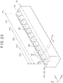
- Fig. 20 shows a step gauge 10 (measurement target) in a first exemplary embodiment.
- the step gauge 10 includes three measurement sections S11, S12, S13.
- the first measurement section S11 is defined between a first measurement start point 11S and a first measurement end point 11E, the first measurement start point 11S being defined on a surface (a surface intersecting the drawing direction Lt) of one of the protrusions 19 at a first end of the step gauge 10, the first measurement end point 11E being defined on a surface of another one of the protrusions 19 at a second end of the step gauge 10.
- the length of the first measurement section is D 11.
- the second measurement section S12 is defined between a second measurement start point 12S and a second measurement end point 12E, the second measurement start point 12S being defined on the same surface as that of the first measurement start point 11S, the second measurement end point 12E being defined on a surface of still another one of the protrusions 19 at a middle portion of the step gauge 10.
- the length of the second measurement section is D12, which is shorter than D11.
- the third measurement section S13 is defined between a third measurement start point 13S and a third measurement end point 13E, the third measurement start point 13S being defined on the same surface as that of the first measurement start point 11S, the third measurement end point 13E being defined on a surface of a further one of the protrusions 19 at the middle portion of the step gauge 10.
- the length of the third measurement section is D13, which is shorter than D12.
- Figs. 21 and 22 show a reference gauge block 20 according to the first exemplary embodiment.
- the reference gauge block 20 includes three gauge blocks 21, 22, 23.
- the gauge blocks 21 to 23 each have the same thickness (a dimension in the vertical direction Hr) and the same width (a dimension in the width direction Wr), but are different in lengths (a dimension in the drawing direction Lr).
- the gauge blocks 21, 22, 23 respectively have a length D21, length D22 and length D23 corresponding to the above-described three measurement sections S11, S12, S13 (each having lengths D11, D12, D13) of the step gauge 10.
- gauge blocks 21, 22, 23 define three reference sections S21, S22, S23 on the reference gauge block 20.
- the first reference section S21 is defined between a first reference start point 21S and a first reference end point 21E respectively at first and second end faces of the gauge block 21.
- the first reference section length D21 is set to be shorter than the corresponding first measurement section length D11 by the length Dp of one of the protrusions 19.
- the second reference section S22 is defined between a second reference start point 22S and a second reference end point 22E respectively at first and second end faces of the gauge block 22.
- the second reference section length D22 is set to be shorter than the corresponding second measurement section length D12 by the length Dp of one of the protrusions 19.
- the three gauge blocks 21, 22, 23 of the reference gauge block 20 are layered in a descending order of the length thereof and are attached by fixtures 28, 29 penetrating through the gauge blocks 21, 22, 23. Specifically, the two gauge blocks 21, 22 are fastened by the fixture 28 and the three gauge blocks 21, 22, 23 are fastened by the fixture 29.
- the gauge blocks 21 to 23 are not necessarily fastened by the fixture 29 but may be rigidly attached while being layered by other mechanism(s) such as mutual bonding and bundling with a use of a belt-shaped member.
- Insert holes 26, 27 are formed on each of the two gauge blocks 21, 22 (i.e. two of the three gauge blocks 21 to 23 except for the uppermost gauge block 23).
- the insert hole 27 is formed at a position of the middle portions of the gauge blocks 21, 22 to be overlapped with the second end at which the third reference end point 23E of the gauge block 23 is defined.
- the lower face of the step gauge 10 is supported by supports 32, 33 provided in the temperature-controlled chamber 30.
- the support 32 restricts the displacement of the step gauge 10 in the drawing direction Lt and the width direction Wt. However, all of the rotations of the step gauge 10 around axes in the drawing direction Lt, the vertical direction Ht and the width direction Wt are permitted.
- the moving support 33 restricts the displacement of the step gauge 10 in the width direction Wt but permits the displacement of the step gauge 10 in the drawing direction Lt. Further, all of the rotations of the step gauge 10 around axes in the drawing direction Lt, the vertical direction Ht and the width direction Wt are permitted.
- the supports 32, 33 can be exemplarily provided by a so-called kinematic mount (restriction of translational three-degree-of-freedom (X, Y, Z) by a contact of a sphere and a conical hole, restriction of rotational two-degree-of-freedom (pitch, yaw) by a contact of a sphere and a V-shaped groove, restriction of single-degree-of-freedom (roll) by a contact between a sphere and a plane).
- a so-called kinematic mount restriction of translational three-degree-of-freedom (X, Y, Z) by a contact of a sphere and a conical hole
- restriction of single-degree-of-freedom (roll) by a contact between a sphere and a plane restriction of single-degree-of-freedom
- the drawing direction Lt of the step gauge 10 is always kept constant and the extension/contraction due to thermal deformation mainly appears on the side of the first to third measurement end points 11E to 13E.
- the lower face of the reference gauge block 20 is supported by supports 34, 35 provided in the temperature-controlled chamber 30 and the upper face of the reference gauge block 20 is pressed by pressing devices 36, 37.
- the fixed support 34 restricts the displacement of the reference gauge block 20 in the drawing direction Lt and the width direction Wt. However, all of the rotations of the reference gauge block 10 around axes in the drawing direction Lt, the vertical direction Ht and the width direction Wt are permitted.
- the moving support 35 restricts the displacement of the reference gauge block 20 in the width direction Wt but permits the displacement of the reference gauge block 20 in the drawing direction Lt. Further, all of the rotations of the reference gauge block 20 around axes in the drawing direction Lt, the vertical direction Ht and the width direction Wt are permitted.
- the supports 34, 35 can also be exemplarily provided by a so-called kinematic mount (restriction of translational three-degree-of-freedom (X, Y, Z) by a contact of a sphere and a conical hole, restriction of rotational two-degree-of-freedom (pitch, yaw) by a contact of a sphere and a V-shaped groove, restriction of single-degree-of- freedom (roll) by a contact between a sphere and a plane).
- a so-called kinematic mount restriction of translational three-degree-of-freedom (X, Y, Z) by a contact of a sphere and a conical hole
- restriction of rotational two-degree-of-freedom pitch, yaw
- roll restriction of single-degree-of- freedom
- the drawing direction Lr of the reference gauge block 20 is always kept constant and the extension/contraction due to thermal deformation mainly appears on the side of the first to third measurement end points 21E to 23E.
- the pressing devices 36, 37 include resilient coil spring and the like and face the supports 34, 35 to press the reference gauge block 20 against the supports 34, 35.
- the pressing device 37 includes a so-called free ball bearing or a ball caster so as to permit the displacement of the reference gauge block 20 in the drawing direction Lt in a manner corresponding to the moving support 35.
- the reference gauge block 20 When being placed in the temperature-controlled chamber 30, the reference gauge block 20 is disposed at a position shifted with respect to the step gauge 10 toward the first reference end point 21E by the length Dp of one of the protrusions 19 of the step gauge 10.
- the first to third measurement end points 11E to 13E are respectively aligned with the corresponding first to third reference end points 21E to 23E (see Fig. 21 ).
- the reference gauge block 20 is placed in the temperature-controlled chamber 30 between the measurement apertures 31 and the step gauge 10.
- the positions of the first to third reference start points 21S to 23S and the first to third reference end points 21E to 23E of the reference gauge block 20 can be detected by a contact of the probe 46 introduced through the nearest one of the measurement apertures 31.
- the probe 46 can be introduced through the insert holes 26, 27, so that the probe 46 can be brought into contact with the second and third measurement start points 12S, 13S.
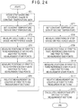
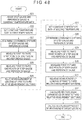
- Fig. 24 shows a measurement process of the CTE of the step gauge 10 using the CTE measuring device 1.
- the temperature-controlled chamber 30 is fixed on the coordinate measuring machine 40 to provide the CTE measuring device 1, and the step gauge 10 and the reference gauge block 20 are housed inside the temperature-controlled chamber 30 (Step ST1).
- Step ST1 When the step gauge 10 and the reference gauge block 20 are set (Step ST1), all of the measurement apertures 31 are closed to set the temperature inside the temperature-controlled chamber 30 at the first temperature t1 and the temperature-controlled chamber 30 is left for a predetermined time to stabilize the temperature (Step ST2).
- the probe 46 is brought into contact with the first to third measurement start points 11S to 13S of the step gauge 10 to measure the positions of the first to third measurement start points 11S to 13S. Further, the probe 46 is brought into contact with the first to third reference start points 21S to 23S of the reference gauge block 20 to measure the positions of the first to third reference start points 21S to 23S (Step ST4).
- the section lengths D11 to D13 of the first to third measurement sections S11 to S13 are calculated based on the positions of the first to third measurement start points 11S to 13S and the first to third measurement end points 11E to 13E. Further, the section lengths D21 to D23 of the first to third reference sections S21 to S23 are calculated based on the positions of the first to third reference start points 21S to 23S and the first to third reference end points 21E to 23E.
- the first to third section lengths D21 to D23 of the reference gauge block 20 are highly accurately measured in advance. Accordingly, the relative measurement of the lengths of the measurement sections S11 to S13 of the step gauge 10 with reference to the reference sections S21 to S23 of the reference gauge block 20 can be performed by correcting the measured first to third section lengths D11 to D13 with the difference between the known values and the measured values of the section lengths D21 to D23 (Step ST6).
- Step ST7 the temperature inside the temperature-controlled chamber 30 is set at the second temperature t2 and the temperature-controlled chamber 30 is left for a predetermined time to stabilize the temperature.
- Steps ST8 to ST11 are performed in a manner similar to the Steps ST2 to ST6 in the measurement at the first temperature t1, Steps ST8, ST9, ST10 and ST11 are performed.
- the details of the Steps ST8 to ST11 are the same as those in the above-described Step ST2 to ST6 and thus duplicated description will be omitted.
- CTEs ⁇ 11 to ⁇ 13 of the first to third measurement sections S11 to S13 can be obtained based on the first to third measurement section lengths D11 to D13 at the first temperature t1 and the first to third measurement section lengths D11 to D13 at the second temperature t2 obtained through the above processes.
- CTE ⁇ 11 of the first measurement section S11 CTE ⁇ 12 of the second measurement section S12 and CTE ⁇ 13 of the third measurement section S13 can be obtained by similar calculations on the other sections S12 and S13 (Step ST12).
- the above-described first exemplary embodiment offers the following advantages.
- the CTEs ⁇ 11 to ⁇ 13 for the first to third measurement sections S11 to S13 can be calculated based on the first to third measurement lengths D11 to D13 at the first temperature t1 and the first to third measurement lengths D11 to D13 at the second temperature t2, thus efficiently measuring the CTE for each of the middle portions of the step gauge 10.
- the CTE of the step gauge 10 having various lengths can be highly accurately measured without using an expensive optical interferometer.
- the reference gauge block 20 is used as a length master and the relative measurement of the length with respect to the reference gauge block 20 is performed in measuring the length of the step gauge 10 using the coordinate measuring machine 40. Accordingly, the results of the length measurement are not dependent on the accuracy of the scale of the coordinate measuring machine 40 but are solely dependent on the accuracy of the reference gauge block 20. Thus, high accuracy of the measurement results can be ensured even when the length of the step gauge 10 is increased.
- both of the reference gauge block 20 and the step gauge 10 are housed in the temperature-controlled chamber 30 in the first exemplary embodiment, it is only necessary to open/close the measurement apertures 31 of the temperature-controlled chamber 30 to introduce/take out the probe 46 in performing the relative measurement of the length of the measurement sections using the coordinate measuring machine 40. In other words, it is not necessary to open the temperature-controlled chamber 30 in order to exchange or take in/out the reference gauge block 20 during the time period from the relative measurement of each of the measurement sections at the first temperature t1 to the relative measurement of each of the measurement sections at the second temperature t2, so that the change in the temperature inside the temperature-controlled chamber 30 as well as the measurement time can be minimized.
- the probe 46 can be introduced through the insert holes 26, 27, so that the positions of all of the measurement start points and the measurement end points can be reliably detected.
- the reference gauge block 20 can be constructed by combining the plurality of existing gauge blocks 21 to 23.
- the reference sections S21 to S23 are respectively defined between end faces (i.e. the between the reference start points 21S to 23S and the reference end points 21E to 23E) of the plurality of gauge blocks 21 to 23. Accordingly, when the plurality of gauge blocks 21 to 23 are combined, the reference gauge block 20 can provide the reference sections S21 to S23 of the plurality of lengths.
- the reference gauge block 20 having the reference sections S21 to S23 with the plurality of lengths can be easily and inexpensively produced.
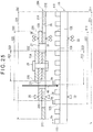
- Figs. 25 and 26 show a reference gauge block 20A and the step gauge 10 of the second exemplary embodiment of the invention.
- the components of the second exemplary embodiment including the CTE measuring device 1 are the same as those in the above-described first exemplary embodiment except for the reference gauge block 20A. Accordingly, only the different component(s) will be described below.
- the reference gauge block 20A according to the second exemplary embodiment includes the three similar gauge blocks 21A to 23A, the gauge blocks 21A to 23A are constructed without aligning the first to third reference start point 21S to 23S when being combined.
- central parts of the measurement sections S11 to S13 of the step gauge 10 in the second exemplary embodiment are aligned (i.e. "nested").
- the three gauge blocks 21A, 22A, 23A are fastened by the fixture 29 provided at the center.
- the gauge blocks 21A to 23A are not necessarily fastened by the fixture 29 but may be rigidly attached while being layered by other mechanism(s) such as mutual bonding and bundling with a use of a belt-shaped member.
- the gauge blocks 21A, 22A are provided with two insert holes 27 in communication with each other.
- the gauge block 21A is provided with the insert holes 26 at two positions.
- the second exemplary embodiment offers the same advantages as those mentioned in the above-described first exemplary embodiment through the measurement processes similar to those in the first exemplary embodiment.
- desired section of the step gauge 10 and the CTE thereof can be measured by selective use of the reference gauge blocks 20, 20A.
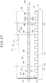
- Figs. 27 and 28 show a reference gauge block 20B and the step gauge 10 of the third exemplary embodiment of the invention.
- the components of the third exemplary embodiment including the CTE measuring device 1 are the same as those in the above-described first exemplary embodiment except for the reference gauge block 20B. Accordingly, only the different component(s) will be described below.
- the three gauge blocks 21 to 23 are combined to provide the reference gauge block 20 and the first to third reference start points 21S to 23S and the first to third reference end points 21E to 23E are defined on the end faces of each of the gauge blocks 21 to 23.
- the reference gauge block 20B in the third exemplary embodiment includes a single gauge block 21B provided with a plurality of insert holes 26B.
- the insert holes 26B also serves as the hole to be detected and central axis positions of the insert holes 26B define the first to third reference start points 21S to 23S and the reference end points 21E to 23E.
- the gauge block 21B is a component similar to the gauge block 21 in the above-described first exemplary embodiment.
- the insert hole 26B also serving as hole to be detected is provided at six points in the gauge block 21B.
- Three left (in Fig. 2 ) insert holes 26B are set at positions to be defined as the first to third reference start points 21S to 23S, in other words, at positions corresponding to the first to third measurement start points 11S to 13S of the step gauge 10 (the measurement target).
- three right (in Fig. 27 ) insert holes 26B are set at positions to be defined as the first to third reference end points 21E to 23E, in other words, at positions corresponding to the first to third measurement end points 11E to 13E of the step gauge 10 (the measurement target).
- the probe 46 is brought into contact with three or more points on the inner circumference of each of the six insert holes 26B also serving as the hole to be detected to measure the position of the central axis of each of the insert holes 26B, i.e. the first to third reference start points 21S to 23S and the first to third reference end points 21E to 23E.
- the probe 46 can be brought into contact with the first to third measurement start points 11S to 13S and the first to third measurement end points 11E to 13E of the step gauge 10 to measure the positions thereof through the six insert holes 26B also serving as the hole to be detected.
- the reference section lengths of the reference gauge block 20B can be measured and the relative measurement of the measurement section lengths of the step gauge 10 can be performed based on the measurements of the above points, thereby achieving the same advantages as those in the above-described first exemplary embodiment through the same measurement processes as those in the above-described first exemplary embodiment.
- one of the protrusions 19 of the step gauge 10 defined with the first measurement start point 11S is disposed so that the end face defined with the first measurement start point 11S, one of the lateral faces and the upper face appear in an opening area of one of the insert holes 26B of the reference gauge block 20B.
- the probe 46 can be inserted from above into the one of the insert holes 26B to bring the probe 46 into contact with the end face, the lateral face and the upper face of the one of the protrusions 19 to detect the positions of the end face, the lateral face and the upper face and measure the orientation of the step gauge 10 (an error between the drawing direction Lt and the Y-axis direction) (Step ST3 in the first exemplary embodiment in Fig. 24 ).
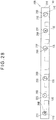
- Figs. 29 and 30 show a reference gauge block 20C and the step gauge 10 of the fourth exemplary embodiment of the invention.
- the components of the fourth exemplary embodiment including the CTE measuring device 1 are the same as those in the above-described first exemplary embodiment except for the reference gauge block 20C. Accordingly, only the different component(s) will be described below.
- the three gauge blocks 21 to 23 are combined to provide the reference gauge block 20 and the first to third reference start points 21S to 23S and the first to third reference end points 21E to 23E are defined on the end faces of each of the gauge blocks 21 to 23.
- the reference gauge block 20C of the fourth exemplary embodiment includes a single gauge block 21C provided with a plurality of insert holes 26C, and six balls 24 to be measured fixed on the surface of the gauge block 21C near the insert holes 26C.
- Axis lines each passing through the center of each of the balls 24 and orthogonal to the gauge block 21C define the first to third reference start points 21S to 23S and the reference end points 21E to 23E.
- the probe 46 is brought into contact with four or more points on the spherical surface of each of the balls 24 to measure the positions of the axis lines showing the center of each of the balls 24 and the first to third reference start points 21S to 23S and the first to third reference end points 21E to 23E.
- the reference section lengths of the reference gauge block 20C can be measured and the relative measurement of the measurement section lengths of the step gauge 10 can be performed based on the measurements of the above points, thereby achieving the same advantages as those in the above-described first exemplary embodiment through the same measurement processes as those in the above-described first exemplary embodiment.
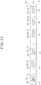
- Figs. 31 and 32 show a reference gauge block 20D and the step gauge 10 of the fifth exemplary embodiment of the invention.
- the components of the fifth exemplary embodiment including the CTE measuring device 1 are the same as those in the above-described first exemplary embodiment except for the reference gauge block 20D. Accordingly, only the different component(s) will be described below.
- the reference gauge block 20D of the fifth exemplary embodiment includes a single gauge block 21D provided with a plurality of insert holes 26D, and six cylinders 25 to be measured fixed on the surface of the gauge block 21D near the insert holes 26D.
- Central axis of the cylinders 25 define the first to third reference start points 21S to 23S and the reference end points 21E to 23E.
- the cylinders 25 are exemplarily made of the same material as that of the gauge block 21D and each have highly accurately finished outer circumferential cylindrical surface.
- the cylinders 25 are fixed on predetermined positions on the surface of the gauge block 21D using an adhesive or the like.
- the probe 46 is brought into contact with three or more points on the cylindrical surface of each of the cylinders 25 to measure the positions of the axis lines showing the center of each of the cylinders 25 (i.e. the first to third reference start points 21S to 23S and the first to third reference end points 21E to 23E).
- the probe 46 can be brought into contact with the first to third measurement start points 11S to 13S and the first to third measurement end points 11E to 13E of the step gauge 10 to measure the positions thereof through the insert holes 26D.
- the reference section lengths of the reference gauge block 20D can be measured and the relative measurement of the measurement section lengths of the step gauge 10 can be performed based on the measurements of the above points, thereby achieving the same advantages as those in the above-described first exemplary embodiment through the same measurement processes as those in the above-described first exemplary embodiment.
- Fig. 33 shows a step gauge 10 (measurement target) in an sixth comparative example.
- a length Ds of the step gauge 10 is defined by a distance between the first surface 11 of one of the protrusions 19 on the first end and the second surface 12 of the other one of the protrusions 19 on the second end of the step gauge 10.
- the reference gauge block 20E (the reference gauge) is an elongated gauge block extending in the drawing direction Lr.
- a top face, bottom face and lateral faces of the reference gauge block 20E are each parallel to one of the vertical direction Ht and the width direction Wt of the step gauge 10.
- the first reference surface 2A and the second reference surface 2B of the reference gauge block 20E are defined by a pair of end faces at both ends in the drawing direction Lr.
- a reference gauge length Dr is defined by the distance between the first reference surface 2A and the second reference surface 2B.
- the reference gauge block 20E is made of a material of extremely low expansion coefficient or a material of zero expansion coefficient whose expansion due to the temperature change between the first temperature t1 and the second temperature t2 (described later) is below a detectable limit. It should be noted that the reference gauge block 20E may be made of a material whose expansion coefficient is known.
- the step gauge 10 and the reference gauge block 20E are placed in the temperature-controlled chamber 30 in parallel with each other.
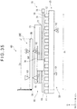
- the measurement target support base 50 and the reference gauge support base 60 as shown in Fig. 35 are placed in the temperature-controlled chamber 30.
- the measurement target support base 50 includes the first measurement target support base 51 configured to support the lower face of the step gauge 10 near the first surface 11 and the second measurement target support base 52 configured to support the lower face of the step gauge 10 near the second surface 12.
- the first measurement target support base 51 is configured to restrict the displacement of the step gauge 10 in the drawing direction Lt
- the second measurement target support base 52 is configured to permit the displacement of the step gauge 10 in the drawing direction Lt.
- the reference gauge support base 60 includes the first reference gauge support base 61 configured to support the lower face of the step gauge 10 near the first reference surface 2A and the second reference gauge support base 62 configured to support the lower face of the step gauge 10 near the second reference surface 2B.
- the reference gauge support base 60 includes a first pressing portion 63 configured to push the upper face of the step gauge 10 to press the step gauge 10 against the first reference gauge support base 61, and a second pressing portion 64 configured to push the upper face of the step gauge 10 to press the step gauge 10 against the second reference gauge support base 62.
- the first reference gauge support base 61 and the first pressing portion 63 are configured to restrict the displacement of the step gauge 10 in the drawing direction Lt, whereas the second reference gauge support base 62 and the second pressing portion 64 are configured to permit the displacement of the step gauge 10 in the drawing direction Lt.
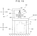
- All of the first reference gauge support base 61, the second reference gauge support base 62, the first pressing portion 63 and the second pressing portion 64 are supported by a movable base 76.
- the movable base 76 is horizontally movable on a pair of rails 77 via rollers with a movement direction thereof being restricted by a guide rail 73 provided along a lateral face of the movable base 76, so that the movable base 76 is configured to move along the drawing directions Lt, Lr.
- a ball screw mechanism 74 is connected to the movable base 76.
- the ball screw mechanism 74 is driven by a motor 75 to move the movable base 76 and the reference gauge block 20E to a desired position along the drawing directions Lt, Lr.
- the movable base 76, the rail 77, the guide rail 73, the ball screw mechanism 74 and the motor 75 define a reference gauge drive mechanism 70.
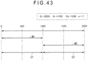
- a plurality of relative measurement sections corresponding to the reference gauge block 20E (length Dr) are allocated to the measurement target section (length Dt) of the step gauge 10.
- the relative measurement section is allocated to the measurement target section as follows. Initially, the reference gauge block 20E whose length (reference gauge length Dr) is in an integer ratio to the measurement target section length Dt is used. A fraction dividing the difference between the measurement target section length Dt and the reference gauge length Dr by an integer is defined as a shift amount Dd. Then, an allocated number n, which is larger by one than a division of the difference between the measurement target section length Dt and the reference gauge length Dr by the shift amount Dd, of the relative measurement sections are allocated to the measurement target section.
- the measurement target section each having the length Dt is allocated with the n relative measurement sections having the length Dr, where start points of each of the relative measurement sections are sequentially shifted by the shift amount Dd.
- the start point of an nth relative measurement section Mn is defined at the point displaced from the start point of the measurement target section (position P0) by the length of (n - 1) shift amounts Dd.
- the end point of the nth relative measurement section is defined at a point displaced from the start point of the measurement target section by the length Dr + (n - 1)•Dd.
- Fig. 36 shows an arrangement of the relative measurement sections in the sixth comparative example.
- the start point of a first relative measurement section M1 coincides with the start point (position P0) of the measurement target section.
- the end point of the first relative measurement section M1 is defined at a position P4 remote from the start point of the measurement target section by the length Dr.
- the start point of a second relative measurement section M2 is defined at a position P1 shifted from the start point of the measurement target section (position P0) by the shift amount Dd.
- the end point of the second relative measurement section M2 is defined at a position P5 remote from the start point of the measurement target section by the length Dr + 1 ⁇ Dd.
- the start point of a third relative measurement section M3 is defined at a position P2 shifted from the start point of the measurement target section (position P0) by the length of two shift amounts Dd.
- the end point of the third relative measurement section M3 is defined at a position P6 remote from the start point of the measurement target section by the length Dr + 2 ⁇ Dd.
- the relative measurement sections M1 to M3 are arranged at sections each shifted by the shift amount Dd, where the relative measurement sections M1 to M3 are overlapped with each other defining sections for the shift amount Dd.
- a plurality of count sections are allocated in the series of the measurement target sections.
- the CTE ⁇ of the entire measurement target section can be calculated.
- the measurement target section Dt Three relative measurement sections M1 to M3 are defined in the measurement target section Dt in the sixth comparative example, each of the relative measurement sections M1 to M3 being shifted by the shift amount Dd and having the length Dr four times larger than the shift amount Dd. Accordingly, the measurement target section Dt can be divided into the six count sections C1 to C6 each having the length corresponding to the shift amount Dd.
- the first count section C1 is defined at a section having the length Dd between the start point of the first relative measurement section M1 (position P0) and the start point of the second relative measurement section M2 (position P1). Only the first relative measurement section M1 is allocated to the count section C1.
- the second count section C2 is defined at a section having the length Dd between the start point of the second relative measurement section M2 (position P1) and the start point of the third relative measurement section M3 (position P2).
- the first relative measurement section M1 and the second relative measurement section M2 are both allocated to the count section C2 in an overlapping manner.
- the third count section C3 is defined at a section having the length Dd between the start point of the third relative measurement section M3 (position P2) and the middle point of the measurement target section (position P3). All of the first relative measurement section M1, the second relative measurement section M2 and the third relative measurement section M3 are allocated to the count section C3 in an overlapping manner.
- the fourth count section C4 is defined at a section having the length Dd between the middle point of the measurement target section (position P3) and the end point of the first relative measurement section (position P4). All of the first relative measurement section M1, the second relative measurement section M2 and the third relative measurement section M3 are allocated to the count section C4 in an overlapping manner.
- the fifth count section C5 is defined at a section having the length Dd between the end point of the first relative measurement section M1 (position P4) and the end point of the second relative measurement section M2 (position P5).
- the second relative measurement section M2 and the third relative measurement section M3 are both allocated to the count section C5 in an overlapping manner.
- the sixth count section C6 is defined at a section having the length Dd between the end point of the second relative measurement section M2 (position P5) and the end point of the third relative measurement section M3 (position P6). Only the third relative measurement section M3 is allocated to the count section C6.
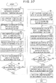
- Fig. 37 shows a measurement process of the CTE of the step gauge 10 using the CTE measuring device 1.
- the temperature-controlled chamber 30 is fixed on the coordinate measuring machine 40 to provide the CTE measuring device 1 and the step gauge 10 and the reference gauge block 20E are placed inside the temperature-controlled chamber 30 (Step S1).
- Step S2 all of the measurement apertures 31 are closed to set the temperature inside the temperature-controlled chamber 30 at the first temperature t1 and the temperature-controlled chamber 30 is left for a predetermined time to stabilize the temperature (Step S2).
- Step S3 the coordinate systems of the step gauge 10 and the reference gauge block 20E are determined.
- one of the measurement apertures 31 of the temperature-controlled chamber 30 is opened to introduce the measurement probe 46 of the coordinate measuring machine 40 and coordinates of a plurality of points on the end faces, upper faces and lateral faces of the step gauge 10 and the reference gauge block 20E are detected, thereby acquiring the orientations of the drawing directions Lt, Lr and the coordinate systems (i.e. a standard of the position measurement) of the step gauge 10 and the reference gauge block 20E.
- Step S3 When the coordinate systems of the step gauge 10 and the reference gauge block 20 are determined (Step S3), relative measurement of the dimensions of the step gauge 10 and the reference gauge block 20E is performed for each of the relative measurement sections M1 to M3 (Steps S4 to S8).
- Step S4 the movable base 76 of the reference gauge drive mechanism 70 is moved to place the reference gauge block 20E at the first relative measurement section M1 (Step S4).
- a first one of the measurement apertures 31 nearest to the start point (position P0) of the first relative measurement section M1 is opened, and the measurement probe 46 of the coordinate measuring machine 40 is introduced through the first one of the measurement apertures 31 to measure the positions of portions (the first surface 11 and the first reference surface 2A in this instance) of each of the step gauge 10 and the reference gauge block 20E corresponding to the start point of the first relative measurement section M1 (Step S5).
- a second one of the measurement apertures 31 nearest to the end point (position P4) of the first relative measurement section M1 is opened, and the measurement probe 46 of the coordinate measuring machine 40 is introduced through the second one of the measurement apertures 31 to measure the positions of portions (the first reference surface 2A of the reference gauge block 20E and corresponding one of the protrusions 19 of the step gauge 10) of each of the step gauge 10 and the reference gauge block 20E corresponding to the end point of the first relative measurement section M1 (Step S6).
- Step S7 the start point and the end point of the step gauge 10 and the reference gauge block 20E in the first relative measurement section M1 are measured. Then, a length Dt11 of the first relative measurement section M1 of the step gauge 10 at the first temperature t1 is measured through the relative measurement with reference to the reference gauge block 20E (Step S7).
- Step S8 When the relative measurement of the first relative measurement section M1 is finished, whether or not a predetermined number of measurement(s) is done checked (Step S8) and the same Steps S4 to S8 are repeated for the second relative measurement section M2 and the third relative measurement section M3.
- Step S9 all of the measurement apertures 31 are closed to set the temperature inside the temperature-controlled chamber 30 at the second temperature t2 and the temperature-controlled chamber 30 is left for a predetermined time to stabilize the temperature.
- Step S10 is the same as the above-described Step S3.
- Steps S11 to S15 are the same as the above-described Steps S4 to S8.
- the above-described first to sixth count sections C1 to C6 are used for the calculation of the CTE ⁇ of the measurement target section.
- the CTE ⁇ of the entire step gauge 10 can be calculated by: defining the plurality of relative measurement section M1 to M3 configured to cover the entirety of the measurement target section of the step gauge 10; performing the relative measurement of the lengths Dt11 to Dt31 and Dt12 to Dt32 of the step gauge 10 in the relative measurement sections; and calculating the section CTEs ⁇ 1 to ⁇ 3 of the relative measurement sections based on the difference in lengths of the relative measurement sections at the first temperature t1 and the second temperature t2.
- the relative measurement using the reference gauge block 20E is possible in each of the relative measurement sections M1 to M3 in the sixth comparative example.
- the relative measurement with respect to the length Dr of the reference gauge block 20E is performed using the coordinate measuring machine 40, so that a highly accurate measurement can be inexpensively performed without using an expensive optical interferometer.
- the relative measurement of the length of the step gauge 10 is performed with respect to the reference gauge block 20E using the coordinate measuring machine 40. Accordingly, the results of the length measurement are not dependent on the accuracy of the scale of the coordinate measuring machine 40 but solely dependent on the accuracy of the reference gauge block 20E. Even when the length of the measurement target section of the step gauge 10 is increased, the length of each of the relative measurement sections M1 to M3 can be set shorter than the length of the measurement target section of the step gauge 10, so that an existing reference gauge block 20E can be used as the reference gauge and the production cost can be reduced.
- the reference gauge block 20E corresponding to the relative measurement sections M1 to M3 is prepared in advance, it is not necessary to introduce/take out the reference gauge block 20E into/out of the temperature-controlled chamber 30 during the measurement process, so that the temperature change in the temperature-controlled chamber 30 and the measurement process time can be minimized during the measurement process.
- the CTE of an entirety of a dimension reference gauge (step gauge 10) having a length exceeding the length of the reference gauge (reference gauge block 20E) can be highly accurately and inexpensively measured in the sixth comparative example.
- the average of the CTEs ⁇ 1 to ⁇ 3 of the sections at which the relative measurement sections M1 to M3 are mutually overlapped can be calculated, so that the CTE ⁇ of the entirety of the measurement target section can be highly accurately and reliably calculated.
- the highly accurate CTE ⁇ can be efficiently measured in the sixth comparative example by: allocating the plurality of count sections C1 to C6 to the measurement target section; averaging the section CTEs ⁇ 1 to ⁇ 3 in each of the count sections; and totalizing the averages after applying the weight coefficient c of the count sections C1 to C6.
- the reference gauge drive mechanism 70 is placed in the temperature-controlled chamber 30 and the reference gauge block 20E is movably arranged to the plurality of relative measurement sections M1 to M3 by the movable base 76, so that the reference gauge block 20E can be sequentially moved to the plurality of relative measurement sections M1 to M3.
- the single reference gauge block 20E can be used in common to the plurality of relative measurement sections M1 to M3, so that fluctuation in the measurement accuracy can be prevented.
- the reference gauge block 20E is made of a material of extremely low expansion coefficient or a material of zero expansion coefficient, it is not necessary to perform temperature correction for the length of the reference gauge block 20E between the first temperature t1 and the second temperature t2.
- the reference gauge block 20E is made of a material having a known expansion coefficient
- a highly accurate relative measurement can be performed by calculating highly accurate length of the reference gauge at the first temperature t1 and the second temperature t2 through a temperature correction.
- the three relative measurement sections M1 to M3 are defined in the above-described sixth comparative example.
- the relative measurement sections M1, M2 in the setting example shown in Fig. 43 are simply arranged with no overlapping therebetween.
- the count sections C1, C2 are the same as the relative measurement sections M1, M2. Since the relative measurement sections M1, M2 are not overlapped in the count sections C1, C2, calculation of average of the count sections and the weight-accompanying totalizing calculation can be omitted.
- the relative measurement sections M1 to M3 in the setting example shown in Fig. 45 are simply arranged with no overlapping therebetween.
- the count sections C1 to C3 are the same as the relative measurement sections M1 to M3. Since the relative measurement sections M1 to M3 are not overlapped in the count sections C1 to C3, calculation of average of the count sections and the weight-accompanying totalizing calculation can be omitted.
- Figs. 46 to 48 show a seventh comparative example of the invention.
- the reference gauge block 20F includes three gauge blocks 201, 202, 203, which are combined and fixed by a fixture 204.
- the gauge blocks 201, 202, 203 are each an existing gauge block having the length Dr and are overlapped with each other with the shift amount Dd.
- the gauge block 201 is the standard of the relative measurement for the first relative measurement section M1.
- the gauge blocks 202, 203 respectively are standards for the relative measurement for the second and third relative measurement sections M2, M3.
- Each of the gauge blocks 201, 202, 203 includes through holes 205 at positions corresponding to end faces of the other gauge blocks.
- the measurement probe 46 of the coordinate measuring machine 40 When the measurement probe 46 of the coordinate measuring machine 40 is brought into contact with the end faces of the gauge blocks for the relative measurement of the relative measurement sections M1 to M3, the measurement probe 46 can reach through the through holes 205 the end faces of the lower gauge blocks 201, 202 covered by the upper gauge blocks 202, 203 and further to a target portion on the step gauge 10 located further below.
- Fig. 48 shows a measurement process of the CTE of the step gauge 10 according to the seventh comparative example.
- the temperature-controlled chamber 30 is fixed on the coordinate measuring machine 40 to provide the CTE measuring device 1 and the step gauge 10 and the reference gauge block 20F are placed inside the temperature-controlled chamber 30 (Step S21).
- Step S22 all of the measurement apertures 31 are closed to set the temperature inside the temperature-controlled chamber 30 at the first temperature t1 and the temperature-controlled chamber 30 is left for a predetermined time to stabilize the temperature.
- Step S23 When the coordinate systems of the step gauge 10 and the reference gauge block 20F are determined (Step S23), relative measurement of the dimensions of the step gauge 10 and the reference gauge block 20F is performed for each of the relative measurement sections M1 to M3 (Steps S24 to S26).
- Step S24 a first one of the measurement apertures 31 nearest to the start point (position P0) of the first relative measurement section M1 is opened, and the measurement probe 46 of the coordinate measuring machine 40 is introduced through the first one of the measurement apertures 31 to measure the positions of portions of each of the step gauge 10 and the reference gauge block 20F corresponding to the start point of the first relative measurement section M1.
- An end face of the gauge block 201 corresponds to the start point of the first relative measurement section M1 in the reference gauge block 20F.
- a second one of the measurement apertures 31 nearest to the start point (position P1) of the second relative measurement section M2 is opened, and the measurement probe 46 of the coordinate measuring machine 40 is introduced through the second one of the measurement apertures 31 to measure the positions of portions of each of the step gauge 10 and the reference gauge block 20F corresponding to the start point of the second relative measurement section M2.
- An end face of the gauge block 202 corresponds to the start point of the second relative measurement section M2 in the reference gauge block 20F.
- a third one of the measurement apertures 31 nearest to the start point (position P2) of the third relative measurement section M3 is opened, and the measurement probe 46 of the coordinate measuring machine 40 is introduced through the third one of the measurement apertures 31 to measure the positions of portions of each of the step gauge 10 and the reference gauge block 20F corresponding to the start point of the third relative measurement section M3.
- An end face of the gauge block 203 corresponds to the start point of the third relative measurement section M3 in the reference gauge block 20F.
- Step S25 a fourth one of the measurement apertures 31 nearest to the end point (position P4) of the first relative measurement section M1 is opened, and the measurement probe 46 of the coordinate measuring machine 40 is introduced through the fourth one of the measurement apertures 31 to measure the positions of portions of each of the step gauge 10 and the reference gauge block 20F corresponding to the end point of the first relative measurement section M1.
- An end face of the gauge block 201 corresponds to the end point of the first relative measurement section M3 in the reference gauge block 20F.
- a fifth one of the measurement apertures 31 nearest to the end point (position P5) of the second relative measurement section M2 is opened, and the measurement probe 46 of the coordinate measuring machine 40 is introduced through the fifth one of the measurement apertures 31 to measure the positions of portions of each of the step gauge 10 and the reference gauge block 20F corresponding to the end point of the second relative measurement section M2.
- An end face of the gauge block 202 corresponds to the end point of the second relative measurement section M2 in the reference gauge block 20F.
- a sixth one of the measurement apertures 31 nearest to the end point (position P6) of the third relative measurement section M3 is opened, and the measurement probe 46 of the coordinate measuring machine 40 is introduced through the third one of the measurement apertures 31 to measure the positions of portions of each of the step gauge 10 and the reference gauge block 20F corresponding to the end point of the third relative measurement section M3.
- An end face of the gauge block 203 corresponds to the end point of the third relative measurement section M3 in the reference gauge block 20F.
- Step S26 the start points and the end points of the step gauge 10 and the reference gauge block 20F in the first to third relative measurement sections M1 to M3 are measured. Then, the lengths Dt11 to Dt31 of the first to third relative measurement sections M1 to M3 of the step gauge 10 at the first temperature t1 are measured through the relative measurement with reference to the reference gauge block 20F (Step S26).
- Step S27 all of the measurement apertures 31 are closed to set the temperature inside the temperature-controlled chamber 30 at the second temperature t2 and the temperature-controlled chamber 30 is left for a predetermined time to stabilize the temperature.
- Step S28 the coordinate systems of the step gauge 10 and the reference gauge block 20F are determined.
- Step S28 When the coordinate systems of the step gauge 10 and the reference gauge block 20F are determined (Step S28), relative measurement of the dimensions of the step gauge 10 and the reference gauge block 20F is performed for each of the relative measurement sections M1 to M3 (Steps S29 to S31). It should be noted that Steps S27 to 31 are the same as the above-described Steps S22 to S26.
- Steps S32 and S33 are the same as Steps S16 and S17 in the above-described sixth comparative example.
- the seventh comparative example provides the same advantages as those mentioned in the above-described sixth comparative example.
- a plurality of the relative measurement sections M1 to M3 can be measured using the single reference gauge block 20F, so that a movement operation of the reference gauge block 20F and the like can be omitted.
- the reference gauge block 20F of the seventh comparative example is provided by combining the gauge blocks 201 to 203 each having the reference gauge lengths Dr corresponding to the lengths of the relative measurement sections M1 to M3 and fixing the gauge blocks 201 to 203 with the position thereof being shifted with each other by the shift amount Dd. Accordingly, the reference gauge block 20F can be easily produced and, high accuracy can be ensured equally in all of the relative measurement sections M1 to M3 using an existing gauge block as the gauge blocks 201 to 203.
- the through holes 205 penetrating through the top and bottom sides at middle portions of the gauge blocks 201 to 203 are provided so that an end of the other gauge block(s) is visible through the through holes 205 in the reference gauge block 20F of the seventh comparative example. Accordingly, even when the relative measurement section of the measurement target lies at a position hidden behind the reference gauge block 20F, the measurement probe 46 of the coordinate measuring machine 40 can be introduced through one of the through holes 205.
- the first reference gauge support bases 61, 61A and the second reference gauge support bases 62, 62A in the first to fifth comparative examples include the preloading unit 609 that is configured to reliably keep the contact between the lower sides of the reference gauges and the contact portions 601, 602, 603.
- the preloading unit 609 may be omitted.
- the length Dx from the first surface 11 to the second surface 12 is measured as the length of the step gauge 10 in the above-described first comparative example.
- the length of the step gauge 10 and the CTE between the first surface 11 and the second surface 12 can be measured when the end faces of the step gauge 10 are defined as the first surface 11 and the second surface 12.
- the first surface 11 and the second surface 12 may be defined at an end face of one of the protrusions 19 at a middle portion of the step gauge 10, so that the length and the CTE of the middle portion can be measured.
- the measurement target in the above-described first to fifth comparative examples is the step gauge 10
- the measurement target may alternatively be a gauge block or other dimension reference gauge.
- the reference gauge is not necessarily the reference gauge block 2 but may alternatively be a dedicated reference gauge or a step gauge 10 similar to the measurement target but in a form of a highly accurately calibrated master gauge.
- the above reference gauge is preferably made of a material of extremely low expansion coefficient or a material of zero expansion coefficient whose expansion due to the temperature change between the first temperature t1 and the second temperature t2 is below a detectable limit, or made of a material whose expansion coefficient is known.
- the second reference surface 2B of the reference gauge block 2 (reference gauge) and the second surface 12 of the step gauge 10 (measurement target) are coplanarly arranged in the above-described first to fifth comparative examples, the first reference surface 2A and the first surface 11 may alternatively be coplanarly arranged or the ends of the reference gauge and the measurement target may be shifted with each other in a plan view.
- the coplanar arrangement of one of the ends of the reference gauge and the measurement target maximizes the difference in the lengths of the reference gauge and the measurement target at the end opposite the coplanarly arranged end, thereby maximizing the margin for the surface detection using the probe of the coordinate measuring machine.
- the CTEs ⁇ 11 to ⁇ 13 of the sections are measured in the above-described first to fifth exemplary embodiments.
- the first to third measurement sections S11 to S13, the measurement start points 11S to 13S and the measurement end points 11E to 13E are defined on the step gauge 10 (measurement target) and the first to third reference sections S21 to S23, the reference start points 21S to 23S and the reference end points 21E to 23E are defined on the reference gauge block 20.
- the measurement target in the above-described first to fifth exemplary embodiments is the step gauge 10
- the measurement target is not necessarily the step gauge 10 but may be provided by other dimension reference gauge that defines a plurality of length standards along the drawing direction Lt.
- the measurement target in the above-described sixth and seventh comparative examples is the step gauge 10
- the measurement target is not necessarily the step gauge 10 but may be provided by other dimension reference gauge that defines a plurality of length standards along the drawing direction Lt.
- the reference gauge is not necessarily the reference gauge block 20E or 20F but may alternatively be a dedicated reference gauge or a step gauge 10 similar to the measurement target in a form of a highly accurately calibrated master gauge.
Landscapes
- Physics & Mathematics (AREA)
- General Physics & Mathematics (AREA)
- General Health & Medical Sciences (AREA)
- Chemical & Material Sciences (AREA)
- Analytical Chemistry (AREA)
- Biochemistry (AREA)
- Life Sciences & Earth Sciences (AREA)
- Health & Medical Sciences (AREA)
- Immunology (AREA)
- Pathology (AREA)
- A Measuring Device Byusing Mechanical Method (AREA)
- Length-Measuring Instruments Using Mechanical Means (AREA)
- Length Measuring Devices With Unspecified Measuring Means (AREA)
- Investigating Or Analyzing Materials Using Thermal Means (AREA)
Claims (5)
- Procédé de mesure de coefficient de dilation thermique d'une cible de mesure sous la forme d'un calibre de référence de dimension (10), le coefficient de dilation thermique étant mesuré pour une pluralité de sections de mesure (S11, S12, S13) définies par une pluralité de paires constituées d'un point de départ de mesure (11S, 12S, 13S) et d'un point de fin de mesure (11E, 12E, 13E) de la cible de mesure qui sont distancés dans une direction de traction de la cible de mesure, le procédé comportant les étapes consistant à :mettre en oeuvre : un calibre de référence (20) comportant une pluralité de paires de points de départ de référence (21S, 22S, 23S) et de points de fin de référence (21E, 22E, 23E) qui définissent une pluralité de sections de référence (S21, S22, S23) correspondant à la pluralité de sections de mesure (S11, S12, S13), une longueur (D21, D22, D23) de chacune des sections de référence (S21, S22, S23) étant connue, et dans lequel, au niveau de chacune d'une ou de plusieurs positions, lesdites une ou plusieurs positions correspondant chacune à un point respectif parmi les points de départ de mesure (11S, 12S, 13S) et les points de fin de mesure (11E, 12E, 13E) de la cible de mesure, se trouve un trou d'insertion (26, 27) ; une chambre à température contrôlée (30) configurée pour ajuster une température intérieure de celle-ci et pour recevoir la cible de mesure et le calibre de référence (20), la chambre à température contrôlée comportant une surface de mesure comportant un orifice de mesure (31) ; et une machine de mesure de coordonnées (40) comportant une sonde de mesure (46) qui est en mesure d'être introduite dans la partie intérieure de la chambre à température contrôlée (30) au travers de l'orifice de mesure (31), la sonde de mesure (46) de la machine de mesure de coordonnées (40) étant en mesure d'être insérée au travers du trou d'insertion (26, 27) ;supporter la cible de mesure et le calibre de référence (20) de manière parallèle dans la partie intérieure de la chambre à température contrôlée (30) ;avec la température intérieure de la chambre à température contrôlée qui est réglée à une première température, détecter des positions des points de départ de mesure (11S, 12S, 13S), des points de fin de mesure (11E, 12E, 13E), des points de départ de référence (21S, 22S, 23S) et des points de fin de référence (21E, 22E, 23E) en utilisant la sonde de mesure (46) ;effectuer une première mesure relative pour une longueur (D11, D21, D13) de chacune de la pluralité de sections de mesure (S11, S12, S13) en fonction d'une longueur (D21, D22, D23) d'une section correspondante des sections de référence (S21, S22, S23) ;avec la température intérieure de la chambre à température contrôlée qui est réglée à une deuxième température, détecter des positions des points de départ de mesure (11S, 12S, 13S), des points de fin de mesure (11E, 12E, 13E), des points de départ de référence (21S, 22S, 23S) et des points de fin de référence (21E, 22E, 23E) en utilisant la sonde de mesure (46) ;effectuer une deuxième mesure relative pour la longueur (D11, D21, D13) de chacune de la pluralité de sections de mesure (S11, S12, S13) en fonction d'une longueur (D21, D22, D23) d'une section correspondante des sections de référence (S21, S22, S23) ; etcalculer le coefficient de dilation thermique de chacune de la pluralité de sections de mesure (S11, S12, S13) en fonction de la longueur mesurée (D11, D12, D13) à la première température et de la longueur mesurée (D11, D12, D13) à la deuxième température.
- Procédé de mesure de coefficient de dilation thermique d'un calibre de référence de dimension selon la revendication 1, dans lequel
les points de départ de référence (21S, 22S, 23S) et les points de fin de référence (21E, 22E, 23E) du calibre de référence (20) sont chacun définis par l'un des points suivants :un point sur une surface d'une partie saillante (19) mise en oeuvre sur le calibre de référence (20) croisant la direction de traction ;un point virtuel sur un axe central d'un trou cylindrique (26B) devant être détecté mis en oeuvre sur le calibre de référence (20), le point virtuel étant obtenu par la détection d'une surface circonférentielle intérieure du trou (26B) devant être détecté en utilisant la machine de mesure de coordonnées (40) ;un point virtuel sur un axe central d'un cylindre cylindrique (25) devant être mesuré mis en oeuvre sur le calibre de référence (20), le point virtuel étant obtenu par la détection d'une surface circonférentielle extérieure du cylindre (25) devant être mesuré en utilisant la machine de mesure de coordonnées (40) ; etun point virtuel indiquant un centre d'une boule (24) devant être mesurée mise en oeuvre sur le calibre de référence (20), le point virtuel étant obtenu par la détection d'une surface circonférentielle extérieure de la boule (24) devant être mesurée en utilisant la machine de mesure de coordonnées (40). - Procédé de mesure de coefficient de dilation thermique d'un calibre de référence de dimension selon la revendication 1 ou la revendication 2, dans lequel
le calibre de référence (20) est sous une forme d'une combinaison d'une pluralité de calibres à bouts plans (21, 22, 23) correspondant aux sections de référence (S21, S22, S23), des faces d'extrémité des calibres à bouts plans (21, 22, 23) définissant les points de départ de référence (21S, 22S, 23S) et les points de fin de référence (21E, 22E, 23E). - Procédé de mesure de coefficient de dilation thermique d'un calibre de référence de dimension selon l'une quelconque des revendications 1 à 3, dans lequel
le calibre de référence (2) est réalisé en un matériau à coefficient de dilation extrêmement faible ou un matériau à coefficient de dilation nul dont la dilatation due à un changement de température entre la première température et la deuxième température est inférieure à une limite détectable, ou est réalisé en un matériau dont le coefficient de dilation est connu. - Dispositif de mesure de coefficient de dilation thermique d'une cible de mesure sous la forme d'un calibre de référence de dimension (10), le coefficient de dilation thermique de la cible de mesure étant mesuré pour une pluralité de sections de mesure (S11, S12, S13) définies par une pluralité de paires constituées d'un point de départ de mesure (11S, 12S, 13S) et d'un point de fin de mesure (11E, 12E, 13E) de la cible de mesure qui sont distancés dans une direction de traction de la cible de mesure, le dispositif de mesure du coefficient de dilation thermique comportant :un calibre de référence (20) comportant une pluralité de paires de points de départ de référence (21S, 22S, 23S) et de points de fin de référence (21E, 22E, 23E) qui définissent une pluralité de sections de référence (S21, S22, S23) correspondant à la pluralité de sections de mesure (S11, S12, S13), une longueur (D21, D22, D23) de chacune des sections de référence (S21, S22, S23) étant connue ;une chambre à température contrôlée (30) configurée pour ajuster une température intérieure de celle-ci et pour recevoir la cible de mesure et le calibre de référence (20), la chambre à température contrôlée comportant une surface de mesure comportant un orifice de mesure (31) ; etune machine de mesure de coordonnées (40) comportant une sonde de mesure (46) qui est en mesure d'être introduite dans une partie intérieure de la chambre à température contrôlée (30) au travers de l'orifice de mesure (31) ;et caractérisé en ce que, au niveau de chacune desdites une ou plusieurs positions, chacune desdites une ou plusieurs positions correspondant à un point respectif parmi les points de départ de mesure (11S, 12S, 13S) et les points de fin de mesure (11E, 12E, 13E) de la cible de mesure, se trouve un trou d'insertion (26, 27), la sonde de mesure (46) de la machine de mesure de coordonnées (40) étant en mesure d'être insérée au travers du trou d'insertion (26, 27).
Applications Claiming Priority (4)
| Application Number | Priority Date | Filing Date | Title |
|---|---|---|---|
| JP2015188093A JP2017062192A (ja) | 2015-09-25 | 2015-09-25 | 寸法基準器の線膨張係数測定方法および測定装置 |
| JP2015215240A JP6688039B2 (ja) | 2015-10-30 | 2015-10-30 | 寸法基準器の線膨張係数測定方法および測定装置 |
| JP2015215241A JP6594737B2 (ja) | 2015-10-30 | 2015-10-30 | 寸法基準器の線膨張係数測定方法 |
| EP16190535.1A EP3147656B1 (fr) | 2015-09-25 | 2016-09-26 | Mesure de coefficient de dilatation thermique |
Related Parent Applications (2)
| Application Number | Title | Priority Date | Filing Date |
|---|---|---|---|
| EP16190535.1A Division-Into EP3147656B1 (fr) | 2015-09-25 | 2016-09-26 | Mesure de coefficient de dilatation thermique |
| EP16190535.1A Division EP3147656B1 (fr) | 2015-09-25 | 2016-09-26 | Mesure de coefficient de dilatation thermique |
Publications (2)
| Publication Number | Publication Date |
|---|---|
| EP3190405A1 EP3190405A1 (fr) | 2017-07-12 |
| EP3190405B1 true EP3190405B1 (fr) | 2018-04-18 |
Family
ID=56997385
Family Applications (3)
| Application Number | Title | Priority Date | Filing Date |
|---|---|---|---|
| EP17152926.6A Active EP3190405B1 (fr) | 2015-09-25 | 2016-09-26 | Mesure de coefficient de dilatation thermique |
| EP17152925.8A Active EP3190404B1 (fr) | 2015-09-25 | 2016-09-26 | Procédé de mesure de coefficient de dilatation thermique |
| EP16190535.1A Active EP3147656B1 (fr) | 2015-09-25 | 2016-09-26 | Mesure de coefficient de dilatation thermique |
Family Applications After (2)
| Application Number | Title | Priority Date | Filing Date |
|---|---|---|---|
| EP17152925.8A Active EP3190404B1 (fr) | 2015-09-25 | 2016-09-26 | Procédé de mesure de coefficient de dilatation thermique |
| EP16190535.1A Active EP3147656B1 (fr) | 2015-09-25 | 2016-09-26 | Mesure de coefficient de dilatation thermique |
Country Status (3)
| Country | Link |
|---|---|
| US (1) | US10352678B2 (fr) |
| EP (3) | EP3190405B1 (fr) |
| CN (1) | CN107014858B (fr) |
Families Citing this family (13)
| Publication number | Priority date | Publication date | Assignee | Title |
|---|---|---|---|---|
| GB201308467D0 (en) * | 2013-05-10 | 2013-06-19 | Renishaw Plc | Method and Apparatus for Inspecting Workpieces |
| US9958406B1 (en) * | 2013-12-06 | 2018-05-01 | Bloom Energy Corporation | Method of measurement and estimation of the coefficient of thermal expansion in components |
| JP6484108B2 (ja) * | 2015-05-22 | 2019-03-13 | 株式会社ミツトヨ | 形状測定装置の制御方法 |
| JP6990024B2 (ja) * | 2016-12-22 | 2022-01-12 | 株式会社ミツトヨ | 線膨張係数測定方法および測定装置 |
| CN106679525B (zh) * | 2017-03-07 | 2022-04-26 | 甘太喜 | 一种高稳定性步距规及其制备方法 |
| JP2018194430A (ja) * | 2017-05-17 | 2018-12-06 | 株式会社ミツトヨ | ステップゲージ |
| CN109682335A (zh) * | 2018-12-25 | 2019-04-26 | 江西远成汽车技术股份有限公司 | 导向臂展开长度计算方法 |
| CN109765262B (zh) * | 2019-02-26 | 2024-01-12 | 陈艺征 | 一种热膨胀系数测量仪 |
| US12123701B2 (en) * | 2020-08-13 | 2024-10-22 | Optipro Systems, LLC | Surface metrology systems and methods thereof |
| CN112393665B (zh) * | 2020-11-26 | 2024-02-06 | 西安航天计量测试研究所 | 一种标准间隙样板 |
| CN114252474B (zh) * | 2021-12-22 | 2024-11-01 | 赛迈科先进材料股份有限公司 | 一种高效率石墨热膨胀测试仪 |
| CN117161828A (zh) * | 2023-09-15 | 2023-12-05 | 中国第一汽车股份有限公司 | 一种环规恒温装置 |
| CN119936105A (zh) * | 2024-12-27 | 2025-05-06 | 河北交通投资集团有限公司 | 一种基于沥青混合料芯样的收缩系数计算方法 |
Family Cites Families (29)
| Publication number | Priority date | Publication date | Assignee | Title |
|---|---|---|---|---|
| DE3841488A1 (de) * | 1988-12-09 | 1990-06-13 | Zeiss Carl Fa | Koordinatenmessgeraet mit einem oder mehreren fuehrungselementen aus aluminium |
| DE8910636U1 (de) | 1989-09-06 | 1989-10-12 | Carl Zeiss, 89518 Heidenheim | Längenmeßeinrichtung |
| US5446971A (en) * | 1993-01-14 | 1995-09-05 | Leitz Messtechnik Gmbh | Method for the dimensional measurement of workpieces |
| DE4436782B4 (de) * | 1993-10-21 | 2006-05-04 | Carl Zeiss Industrielle Messtechnik Gmbh | Verfahren und Vorrichtung zur Vermessung von Prüflingen auf einem Koordinatenmeßgerät |
| IT1296727B1 (it) * | 1997-10-09 | 1999-07-15 | Dea Brown & Sharpe S P A Ora B | Metodo di determinazione dell'incertezza di misura di una macchina di misura a coordinate. |
| JP3814397B2 (ja) * | 1997-12-22 | 2006-08-30 | 株式会社オハラ | 膨張測定装置 |
| EP0969264A3 (fr) * | 1998-05-06 | 2001-06-13 | Dr. Johannes Heidenhain GmbH | Capteur plan et son application dans un procédé de compensation pour des déformations thermiques |
| JP3609271B2 (ja) * | 1998-10-22 | 2005-01-12 | 株式会社ミツトヨ | 変位測定装置 |
| JP2001330428A (ja) * | 2000-05-23 | 2001-11-30 | Natl Inst Of Advanced Industrial Science & Technology Meti | 3次元測定機の測定誤差評価方法及び3次元測定機用ゲージ |
| JP3970510B2 (ja) * | 2000-09-28 | 2007-09-05 | 三菱電機株式会社 | 線膨張係数測定装置 |
| DE10049718A1 (de) * | 2000-10-07 | 2002-04-18 | Heidenhain Gmbh Dr Johannes | Vorrichtung zur Erfassung einer thermisch bedingten Längenausdehnung eines Maschinenteils |
| DE10138138A1 (de) * | 2001-08-09 | 2003-02-20 | Zeiss Carl | Korrektur des Temperaturfehlers bei einer Messung mit einem Koordinatenmessgerät |
| JP3897655B2 (ja) | 2002-08-02 | 2007-03-28 | 株式会社ミツトヨ | 線膨張係数測定装置 |
| JP2004226369A (ja) | 2003-01-27 | 2004-08-12 | Mitsutoyo Corp | 線膨張係数測定装置 |
| CN2608939Y (zh) * | 2003-02-26 | 2004-03-31 | 台智精密科技股份有限公司 | 三维测量仪 |
| JP2005083920A (ja) | 2003-09-09 | 2005-03-31 | Mitsutoyo Corp | 線膨張係数測定装置 |
| US7089146B1 (en) * | 2004-09-28 | 2006-08-08 | National Semiconductor Corporation | Apparatus and method for sub-ranging conversion for temperature sensing |
| US20100299094A1 (en) * | 2009-05-23 | 2010-11-25 | Carmar Technology Co., Ltd. | Thermal deformation error compensation method for coordinate measuring machine |
| JP5816475B2 (ja) * | 2010-08-02 | 2015-11-18 | 株式会社ミツトヨ | 産業機械 |
| JP4968600B1 (ja) * | 2011-01-13 | 2012-07-04 | 株式会社東京精密 | 真円度測定装置及びその心ずれ量補正方法 |
| CN102507373B (zh) * | 2011-11-07 | 2014-05-14 | 兰州理工大学 | 材料熔化体积膨胀率/熔融态密度的测量装置 |
| CN103105110A (zh) * | 2011-11-15 | 2013-05-15 | 中机生产力促进中心 | 基于标准尺的大尺寸高精度测量的方法和装置 |
| CN102788810B (zh) | 2012-07-17 | 2014-04-16 | 南京航空航天大学 | 基于光纤光栅的复合材料热膨胀系数测量装置及测量方法 |
| DE102012219417B4 (de) | 2012-10-24 | 2014-10-23 | Carl Zeiss Industrielle Messtechnik Gmbh | Verfahren zur Ermittlung des Ausdehnungskoeffizienten und der gleichmäßigen Temperierung eines Endmaßes |
| KR101365972B1 (ko) | 2013-06-11 | 2014-02-24 | 한국건설생활환경시험연구원 | 콘크리트 열팽창계수 측정 방법 및 장치 |
| JP6366926B2 (ja) * | 2013-11-11 | 2018-08-01 | 株式会社ミツトヨ | 産業機械及びその伸縮量測定方法 |
| EP2899500B1 (fr) * | 2014-01-27 | 2016-09-07 | Hexagon Metrology S.p.A. | Procédé de compensation d'erreurs de mesure dues à des déformations thermiquement induites dans une machine de mesure de coordonnées |
| CN105181737B (zh) * | 2015-09-09 | 2017-10-24 | 哈尔滨工业大学 | 超高温热膨胀系数非接触原位测试的方法及装置 |
| JP6990024B2 (ja) * | 2016-12-22 | 2022-01-12 | 株式会社ミツトヨ | 線膨張係数測定方法および測定装置 |
-
2016
- 2016-09-21 US US15/271,593 patent/US10352678B2/en active Active
- 2016-09-23 CN CN201610849586.8A patent/CN107014858B/zh active Active
- 2016-09-26 EP EP17152926.6A patent/EP3190405B1/fr active Active
- 2016-09-26 EP EP17152925.8A patent/EP3190404B1/fr active Active
- 2016-09-26 EP EP16190535.1A patent/EP3147656B1/fr active Active
Non-Patent Citations (1)
| Title |
|---|
| None * |
Also Published As
| Publication number | Publication date |
|---|---|
| EP3147656A3 (fr) | 2017-04-12 |
| CN107014858B (zh) | 2020-11-20 |
| US20170089683A1 (en) | 2017-03-30 |
| EP3190405A1 (fr) | 2017-07-12 |
| EP3190404A1 (fr) | 2017-07-12 |
| EP3147656A2 (fr) | 2017-03-29 |
| EP3147656B1 (fr) | 2019-01-23 |
| US10352678B2 (en) | 2019-07-16 |
| EP3190404B1 (fr) | 2018-09-26 |
| CN107014858A (zh) | 2017-08-04 |
Similar Documents
| Publication | Publication Date | Title |
|---|---|---|
| EP3147656B1 (fr) | Mesure de coefficient de dilatation thermique | |
| CN102809350B (zh) | 滚珠丝杠轴的累积导程误差测定装置以及测定方法 | |
| CN103250039B (zh) | 材料试验机 | |
| US20120041712A1 (en) | Coordinate measuring machine (cmm) and method of compensating errors in a cmm | |
| Ito et al. | Measurement of form error of a probe tip ball for coordinate measuring machine (CMM) using a rotating reference sphere | |
| Widdershoven et al. | Realization and calibration of the" Isara 400" ultra-precision CMM | |
| Iwasawa et al. | Development of a measuring method for several types of programmed tool paths for NC machine tools using a laser displacement interferometer and a rotary encoder | |
| DE102013017289B4 (de) | Durchführen einer Dickenmessung an bandförmigen Materialien und an Stückgütern | |
| EP1845335B1 (fr) | Procédé de mesure de différence de taille et appareil de mesure de différence de taille | |
| CN111366988A (zh) | 一种六自由度控制的分量式钻孔应变仪整机检测平台 | |
| Li et al. | Online volumetric error compensation for micro-CMMs using embedded multi-DOF (degree-of-freedom) measurement systems based on Abbe and Bryan principles | |
| CN108534725A (zh) | 双孔形位公差测量机构 | |
| Hemming et al. | Interferometric step gauge for CMM verification | |
| Novyanto et al. | Measurement optimization of high accuracy check master based on interferometry method in National Standardization Agency of Indonesia: A preliminary study for measuring range of 10 mm to 400 mm | |
| CN101701786A (zh) | 低热膨胀石英量棒、其标定方法及其应用 | |
| Takamasu | Present problems in coordinate metrology for nano and micro scale measurements | |
| WO2014089653A1 (fr) | Dispositif permettant de mesurer des déformations sur des surfaces | |
| Zhang et al. | Error compensation of cylindrical coordinate measuring machines | |
| JP2017083415A (ja) | 寸法基準器の線膨張係数測定方法、測定装置および基準ゲージ | |
| KR20110096447A (ko) | 초정밀 리니어 스테이지의 오차 측정방법 및 이를 위한 오차 측정장치 | |
| JP6926288B2 (ja) | 寸法基準器の線膨張係数測定方法および測定装置 | |
| CN222652105U (zh) | 一种活塞止口直径测量装置 | |
| CN220062776U (zh) | 一种高精度汽车连续空间弯管检测检具 | |
| CN2771811Y (zh) | 弓架式旋转内径量具 | |
| Bosmans et al. | Design of a precision measurement system using moving linear scales |
Legal Events
| Date | Code | Title | Description |
|---|---|---|---|
| PUAI | Public reference made under article 153(3) epc to a published international application that has entered the european phase |
Free format text: ORIGINAL CODE: 0009012 |
|
| AC | Divisional application: reference to earlier application |
Ref document number: 3147656 Country of ref document: EP Kind code of ref document: P |
|
| AK | Designated contracting states |
Kind code of ref document: A1 Designated state(s): AL AT BE BG CH CY CZ DE DK EE ES FI FR GB GR HR HU IE IS IT LI LT LU LV MC MK MT NL NO PL PT RO RS SE SI SK SM TR |
|
| AX | Request for extension of the european patent |
Extension state: BA ME |
|
| GRAP | Despatch of communication of intention to grant a patent |
Free format text: ORIGINAL CODE: EPIDOSNIGR1 |
|
| 17P | Request for examination filed |
Effective date: 20171024 |
|
| RBV | Designated contracting states (corrected) |
Designated state(s): AL AT BE BG CH CY CZ DE DK EE ES FI FR GB GR HR HU IE IS IT LI LT LU LV MC MK MT NL NO PL PT RO RS SE SI SK SM TR |
|
| RIC1 | Information provided on ipc code assigned before grant |
Ipc: G01N 25/16 20060101AFI20171109BHEP Ipc: G01B 5/008 20060101ALI20171109BHEP |
|
| INTG | Intention to grant announced |
Effective date: 20171128 |
|
| GRAJ | Information related to disapproval of communication of intention to grant by the applicant or resumption of examination proceedings by the epo deleted |
Free format text: ORIGINAL CODE: EPIDOSDIGR1 |
|
| GRAR | Information related to intention to grant a patent recorded |
Free format text: ORIGINAL CODE: EPIDOSNIGR71 |
|
| GRAS | Grant fee paid |
Free format text: ORIGINAL CODE: EPIDOSNIGR3 |
|
| INTC | Intention to grant announced (deleted) | ||
| GRAA | (expected) grant |
Free format text: ORIGINAL CODE: 0009210 |
|
| INTG | Intention to grant announced |
Effective date: 20180302 |
|
| AC | Divisional application: reference to earlier application |
Ref document number: 3147656 Country of ref document: EP Kind code of ref document: P |
|
| AK | Designated contracting states |
Kind code of ref document: B1 Designated state(s): AL AT BE BG CH CY CZ DE DK EE ES FI FR GB GR HR HU IE IS IT LI LT LU LV MC MK MT NL NO PL PT RO RS SE SI SK SM TR |
|
| REG | Reference to a national code |
Ref country code: GB Ref legal event code: FG4D |
|
| REG | Reference to a national code |
Ref country code: CH Ref legal event code: EP |
|
| REG | Reference to a national code |
Ref country code: AT Ref legal event code: REF Ref document number: 991022 Country of ref document: AT Kind code of ref document: T Effective date: 20180515 |
|
| REG | Reference to a national code |
Ref country code: IE Ref legal event code: FG4D |
|
| REG | Reference to a national code |
Ref country code: DE Ref legal event code: R096 Ref document number: 602016002612 Country of ref document: DE |
|
| REG | Reference to a national code |
Ref country code: NL Ref legal event code: MP Effective date: 20180418 |
|
| REG | Reference to a national code |
Ref country code: LT Ref legal event code: MG4D |
|
| PG25 | Lapsed in a contracting state [announced via postgrant information from national office to epo] |
Ref country code: NL Free format text: LAPSE BECAUSE OF FAILURE TO SUBMIT A TRANSLATION OF THE DESCRIPTION OR TO PAY THE FEE WITHIN THE PRESCRIBED TIME-LIMIT Effective date: 20180418 |
|
| PG25 | Lapsed in a contracting state [announced via postgrant information from national office to epo] |
Ref country code: PL Free format text: LAPSE BECAUSE OF FAILURE TO SUBMIT A TRANSLATION OF THE DESCRIPTION OR TO PAY THE FEE WITHIN THE PRESCRIBED TIME-LIMIT Effective date: 20180418 Ref country code: BG Free format text: LAPSE BECAUSE OF FAILURE TO SUBMIT A TRANSLATION OF THE DESCRIPTION OR TO PAY THE FEE WITHIN THE PRESCRIBED TIME-LIMIT Effective date: 20180718 Ref country code: NO Free format text: LAPSE BECAUSE OF FAILURE TO SUBMIT A TRANSLATION OF THE DESCRIPTION OR TO PAY THE FEE WITHIN THE PRESCRIBED TIME-LIMIT Effective date: 20180718 Ref country code: ES Free format text: LAPSE BECAUSE OF FAILURE TO SUBMIT A TRANSLATION OF THE DESCRIPTION OR TO PAY THE FEE WITHIN THE PRESCRIBED TIME-LIMIT Effective date: 20180418 Ref country code: FI Free format text: LAPSE BECAUSE OF FAILURE TO SUBMIT A TRANSLATION OF THE DESCRIPTION OR TO PAY THE FEE WITHIN THE PRESCRIBED TIME-LIMIT Effective date: 20180418 Ref country code: LT Free format text: LAPSE BECAUSE OF FAILURE TO SUBMIT A TRANSLATION OF THE DESCRIPTION OR TO PAY THE FEE WITHIN THE PRESCRIBED TIME-LIMIT Effective date: 20180418 Ref country code: SE Free format text: LAPSE BECAUSE OF FAILURE TO SUBMIT A TRANSLATION OF THE DESCRIPTION OR TO PAY THE FEE WITHIN THE PRESCRIBED TIME-LIMIT Effective date: 20180418 Ref country code: AL Free format text: LAPSE BECAUSE OF FAILURE TO SUBMIT A TRANSLATION OF THE DESCRIPTION OR TO PAY THE FEE WITHIN THE PRESCRIBED TIME-LIMIT Effective date: 20180418 |
|
| PG25 | Lapsed in a contracting state [announced via postgrant information from national office to epo] |
Ref country code: RS Free format text: LAPSE BECAUSE OF FAILURE TO SUBMIT A TRANSLATION OF THE DESCRIPTION OR TO PAY THE FEE WITHIN THE PRESCRIBED TIME-LIMIT Effective date: 20180418 Ref country code: HR Free format text: LAPSE BECAUSE OF FAILURE TO SUBMIT A TRANSLATION OF THE DESCRIPTION OR TO PAY THE FEE WITHIN THE PRESCRIBED TIME-LIMIT Effective date: 20180418 Ref country code: GR Free format text: LAPSE BECAUSE OF FAILURE TO SUBMIT A TRANSLATION OF THE DESCRIPTION OR TO PAY THE FEE WITHIN THE PRESCRIBED TIME-LIMIT Effective date: 20180719 Ref country code: LV Free format text: LAPSE BECAUSE OF FAILURE TO SUBMIT A TRANSLATION OF THE DESCRIPTION OR TO PAY THE FEE WITHIN THE PRESCRIBED TIME-LIMIT Effective date: 20180418 |
|
| REG | Reference to a national code |
Ref country code: AT Ref legal event code: MK05 Ref document number: 991022 Country of ref document: AT Kind code of ref document: T Effective date: 20180418 |
|
| REG | Reference to a national code |
Ref country code: DE Ref legal event code: R097 Ref document number: 602016002612 Country of ref document: DE |
|
| PG25 | Lapsed in a contracting state [announced via postgrant information from national office to epo] |
Ref country code: SK Free format text: LAPSE BECAUSE OF FAILURE TO SUBMIT A TRANSLATION OF THE DESCRIPTION OR TO PAY THE FEE WITHIN THE PRESCRIBED TIME-LIMIT Effective date: 20180418 Ref country code: RO Free format text: LAPSE BECAUSE OF FAILURE TO SUBMIT A TRANSLATION OF THE DESCRIPTION OR TO PAY THE FEE WITHIN THE PRESCRIBED TIME-LIMIT Effective date: 20180418 Ref country code: CZ Free format text: LAPSE BECAUSE OF FAILURE TO SUBMIT A TRANSLATION OF THE DESCRIPTION OR TO PAY THE FEE WITHIN THE PRESCRIBED TIME-LIMIT Effective date: 20180418 Ref country code: DK Free format text: LAPSE BECAUSE OF FAILURE TO SUBMIT A TRANSLATION OF THE DESCRIPTION OR TO PAY THE FEE WITHIN THE PRESCRIBED TIME-LIMIT Effective date: 20180418 Ref country code: EE Free format text: LAPSE BECAUSE OF FAILURE TO SUBMIT A TRANSLATION OF THE DESCRIPTION OR TO PAY THE FEE WITHIN THE PRESCRIBED TIME-LIMIT Effective date: 20180418 Ref country code: AT Free format text: LAPSE BECAUSE OF FAILURE TO SUBMIT A TRANSLATION OF THE DESCRIPTION OR TO PAY THE FEE WITHIN THE PRESCRIBED TIME-LIMIT Effective date: 20180418 |
|
| PLBE | No opposition filed within time limit |
Free format text: ORIGINAL CODE: 0009261 |
|
| STAA | Information on the status of an ep patent application or granted ep patent |
Free format text: STATUS: NO OPPOSITION FILED WITHIN TIME LIMIT |
|
| PG25 | Lapsed in a contracting state [announced via postgrant information from national office to epo] |
Ref country code: SM Free format text: LAPSE BECAUSE OF FAILURE TO SUBMIT A TRANSLATION OF THE DESCRIPTION OR TO PAY THE FEE WITHIN THE PRESCRIBED TIME-LIMIT Effective date: 20180418 Ref country code: IT Free format text: LAPSE BECAUSE OF FAILURE TO SUBMIT A TRANSLATION OF THE DESCRIPTION OR TO PAY THE FEE WITHIN THE PRESCRIBED TIME-LIMIT Effective date: 20180418 |
|
| 26N | No opposition filed |
Effective date: 20190121 |
|
| PG25 | Lapsed in a contracting state [announced via postgrant information from national office to epo] |
Ref country code: MC Free format text: LAPSE BECAUSE OF FAILURE TO SUBMIT A TRANSLATION OF THE DESCRIPTION OR TO PAY THE FEE WITHIN THE PRESCRIBED TIME-LIMIT Effective date: 20180418 |
|
| REG | Reference to a national code |
Ref country code: BE Ref legal event code: MM Effective date: 20180930 |
|
| REG | Reference to a national code |
Ref country code: IE Ref legal event code: MM4A |
|
| PG25 | Lapsed in a contracting state [announced via postgrant information from national office to epo] |
Ref country code: LU Free format text: LAPSE BECAUSE OF NON-PAYMENT OF DUE FEES Effective date: 20180926 |
|
| PG25 | Lapsed in a contracting state [announced via postgrant information from national office to epo] |
Ref country code: IE Free format text: LAPSE BECAUSE OF NON-PAYMENT OF DUE FEES Effective date: 20180926 |
|
| PG25 | Lapsed in a contracting state [announced via postgrant information from national office to epo] |
Ref country code: BE Free format text: LAPSE BECAUSE OF NON-PAYMENT OF DUE FEES Effective date: 20180930 Ref country code: FR Free format text: LAPSE BECAUSE OF NON-PAYMENT OF DUE FEES Effective date: 20180930 |
|
| PG25 | Lapsed in a contracting state [announced via postgrant information from national office to epo] |
Ref country code: MT Free format text: LAPSE BECAUSE OF NON-PAYMENT OF DUE FEES Effective date: 20180926 |
|
| PG25 | Lapsed in a contracting state [announced via postgrant information from national office to epo] |
Ref country code: TR Free format text: LAPSE BECAUSE OF FAILURE TO SUBMIT A TRANSLATION OF THE DESCRIPTION OR TO PAY THE FEE WITHIN THE PRESCRIBED TIME-LIMIT Effective date: 20180418 |
|
| PG25 | Lapsed in a contracting state [announced via postgrant information from national office to epo] |
Ref country code: PT Free format text: LAPSE BECAUSE OF FAILURE TO SUBMIT A TRANSLATION OF THE DESCRIPTION OR TO PAY THE FEE WITHIN THE PRESCRIBED TIME-LIMIT Effective date: 20180418 |
|
| REG | Reference to a national code |
Ref country code: CH Ref legal event code: PL |
|
| PG25 | Lapsed in a contracting state [announced via postgrant information from national office to epo] |
Ref country code: CY Free format text: LAPSE BECAUSE OF FAILURE TO SUBMIT A TRANSLATION OF THE DESCRIPTION OR TO PAY THE FEE WITHIN THE PRESCRIBED TIME-LIMIT Effective date: 20180418 Ref country code: MK Free format text: LAPSE BECAUSE OF NON-PAYMENT OF DUE FEES Effective date: 20180418 Ref country code: HU Free format text: LAPSE BECAUSE OF FAILURE TO SUBMIT A TRANSLATION OF THE DESCRIPTION OR TO PAY THE FEE WITHIN THE PRESCRIBED TIME-LIMIT; INVALID AB INITIO Effective date: 20160926 |
|
| PG25 | Lapsed in a contracting state [announced via postgrant information from national office to epo] |
Ref country code: LI Free format text: LAPSE BECAUSE OF NON-PAYMENT OF DUE FEES Effective date: 20190930 Ref country code: CH Free format text: LAPSE BECAUSE OF NON-PAYMENT OF DUE FEES Effective date: 20190930 Ref country code: IS Free format text: LAPSE BECAUSE OF FAILURE TO SUBMIT A TRANSLATION OF THE DESCRIPTION OR TO PAY THE FEE WITHIN THE PRESCRIBED TIME-LIMIT Effective date: 20180818 |
|
| PG25 | Lapsed in a contracting state [announced via postgrant information from national office to epo] |
Ref country code: SI Free format text: LAPSE BECAUSE OF NON-PAYMENT OF DUE FEES Effective date: 20180926 |
|
| PGFP | Annual fee paid to national office [announced via postgrant information from national office to epo] |
Ref country code: DE Payment date: 20250919 Year of fee payment: 10 |
|
| PGFP | Annual fee paid to national office [announced via postgrant information from national office to epo] |
Ref country code: GB Payment date: 20250919 Year of fee payment: 10 |