EP3190600A1 - Schaltvorrichtung mit aufgehängter mobilkontaktanordnung - Google Patents
Schaltvorrichtung mit aufgehängter mobilkontaktanordnung Download PDFInfo
- Publication number
- EP3190600A1 EP3190600A1 EP16150771.0A EP16150771A EP3190600A1 EP 3190600 A1 EP3190600 A1 EP 3190600A1 EP 16150771 A EP16150771 A EP 16150771A EP 3190600 A1 EP3190600 A1 EP 3190600A1
- Authority
- EP
- European Patent Office
- Prior art keywords
- switching device
- coupling
- contact shaft
- coupling elements
- contact
- Prior art date
- Legal status (The legal status is an assumption and is not a legal conclusion. Google has not performed a legal analysis and makes no representation as to the accuracy of the status listed.)
- Granted
Links
Images








Classifications
-
- H—ELECTRICITY
- H01—ELECTRIC ELEMENTS
- H01H—ELECTRIC SWITCHES; RELAYS; SELECTORS; EMERGENCY PROTECTIVE DEVICES
- H01H9/00—Details of switching devices, not covered by groups H01H1/00 - H01H7/00
- H01H9/02—Bases, casings, or covers
-
- H—ELECTRICITY
- H01—ELECTRIC ELEMENTS
- H01H—ELECTRIC SWITCHES; RELAYS; SELECTORS; EMERGENCY PROTECTIVE DEVICES
- H01H21/00—Switches operated by an operating part in the form of a pivotable member acted upon directly by a solid body, e.g. by a hand
- H01H21/02—Details
- H01H21/18—Movable parts; Contacts mounted thereon
- H01H21/22—Operating parts, e.g. handle
- H01H21/30—Operating parts, e.g. handle not biased to return to a normal position upon removal of operating force
-
- H—ELECTRICITY
- H01—ELECTRIC ELEMENTS
- H01H—ELECTRIC SWITCHES; RELAYS; SELECTORS; EMERGENCY PROTECTIVE DEVICES
- H01H1/00—Contacts
- H01H1/12—Contacts characterised by the manner in which co-operating contacts engage
- H01H1/14—Contacts characterised by the manner in which co-operating contacts engage by abutting
- H01H1/20—Bridging contacts
- H01H1/2041—Rotating bridge
-
- H—ELECTRICITY
- H01—ELECTRIC ELEMENTS
- H01H—ELECTRIC SWITCHES; RELAYS; SELECTORS; EMERGENCY PROTECTIVE DEVICES
- H01H1/00—Contacts
- H01H1/12—Contacts characterised by the manner in which co-operating contacts engage
- H01H1/14—Contacts characterised by the manner in which co-operating contacts engage by abutting
- H01H1/22—Contacts characterised by the manner in which co-operating contacts engage by abutting with rigid pivoted member carrying the moving contact
- H01H1/221—Contacts characterised by the manner in which co-operating contacts engage by abutting with rigid pivoted member carrying the moving contact and a contact pressure spring acting between the pivoted member and a supporting member
- H01H1/225—Contacts characterised by the manner in which co-operating contacts engage by abutting with rigid pivoted member carrying the moving contact and a contact pressure spring acting between the pivoted member and a supporting member the supporting member being pivotable
-
- H—ELECTRICITY
- H01—ELECTRIC ELEMENTS
- H01H—ELECTRIC SWITCHES; RELAYS; SELECTORS; EMERGENCY PROTECTIVE DEVICES
- H01H21/00—Switches operated by an operating part in the form of a pivotable member acted upon directly by a solid body, e.g. by a hand
- H01H21/02—Details
- H01H21/18—Movable parts; Contacts mounted thereon
- H01H21/36—Driving mechanisms
-
- H—ELECTRICITY
- H01—ELECTRIC ELEMENTS
- H01H—ELECTRIC SWITCHES; RELAYS; SELECTORS; EMERGENCY PROTECTIVE DEVICES
- H01H3/00—Mechanisms for operating contacts
- H01H3/02—Operating parts, i.e. for operating driving mechanism by a mechanical force external to the switch
-
- H—ELECTRICITY
- H01—ELECTRIC ELEMENTS
- H01H—ELECTRIC SWITCHES; RELAYS; SELECTORS; EMERGENCY PROTECTIVE DEVICES
- H01H3/00—Mechanisms for operating contacts
- H01H3/32—Driving mechanisms, i.e. for transmitting driving force to the contacts
-
- H—ELECTRICITY
- H01—ELECTRIC ELEMENTS
- H01H—ELECTRIC SWITCHES; RELAYS; SELECTORS; EMERGENCY PROTECTIVE DEVICES
- H01H71/00—Details of the protective switches or relays covered by groups H01H73/00 - H01H83/00
- H01H71/02—Housings; Casings; Bases; Mountings
- H01H71/0207—Mounting or assembling the different parts of the circuit breaker
- H01H71/0228—Mounting or assembling the different parts of the circuit breaker having provisions for interchangeable or replaceable parts
-
- H—ELECTRICITY
- H01—ELECTRIC ELEMENTS
- H01H—ELECTRIC SWITCHES; RELAYS; SELECTORS; EMERGENCY PROTECTIVE DEVICES
- H01H71/00—Details of the protective switches or relays covered by groups H01H73/00 - H01H83/00
- H01H71/10—Operating or release mechanisms
- H01H71/1009—Interconnected mechanisms
Definitions
- the present invention relates to the field of switching devices (such as circuit breakers, contactors, disconnectors and the like) for low voltage applications.
- the present invention relates to a low voltage switching device of the type provided with a suspended rotating mobile contact assembly.
- LV low voltage
- switching devices for LV applications comprise one or more electric poles, each comprising one or more mobile contacts and fixed contacts that can be mutually coupled/ uncoupled.
- Some known switching devices such as the one disclosed in the patent application no. WO2006/120149A1 , are provided with a suspended mobile contact assembly.
- the mobile contact assembly comprises a rotating contact shaft having seats for accommodating the mobile contacts.
- the mobile contact assembly is maintained in an operative position by suitable support elements that are solidly fixed with the outer casing of the switching device and are hinged with the contact shaft to allow the rotation of this latter about a rotation axis (suspended mobile contact assembly).
- the mobile contact assembly is operated by a suitable control mechanism having connecting members (which basically do not have support functions) hinged with the contact shaft.
- Such a control mechanism is adapted to provide a force to rotate the contact shaft during a switching operation of the switching device so that, upon a rotation of said shaft, the mobile contacts of the switching device are moved from a coupling position to an uncoupling position with the corresponding fixed contacts (opening manoeuvre of the switching device), or vice-versa (closing manoeuvre of the switching device).
- the arrangement of the suspended mobile contact assembly is often quite time-consuming to carry out at industrial level, as several parts and components need to be mutually interconnected to mount said assembly in its correct operative position.
- a further object of the present invention is to provide a switching device, in which maintenance interventions can be easily carry out, with particular regard to the mobile contacts of the switching device.
- Another object of the present invention is to provide a switching device easier and cheaper to manufacture and assembly at industrial level with respect to currently available switching devices of the same type.
- the present invention provides a switching device, according to the following claim 1 and related dependent claims.
- the switching device of the invention comprises:
- the switching device comprises one or more coupling elements (to support said contact shaft and provide a mechanical connection between said control mechanism and said contact shaft.
- Said coupling elements comprise:
- said coupling elements are configured as a lever, in which said first coupling point is the point of said lever on which a mechanical load is applied, said second coupling point is the fulcrum point of said lever and said third coupling point is the point of said lever on which a force is applied.
- said coupling elements operate as a lever of first type with an intermediate fulcrum.
- said coupling elements comprise:
- said coupling elements are at least partially accommodated in one or more corresponding coupling recesses of said contact shaft.
- said coupling elements are formed by at least a shaped plate (preferably L-shaped) comprising a supporting leg forming said supporting portion, and a driving leg extending between said second and third coupling points and forms said driving portion.
- the present invention relates to a switching device 1 suitable to be installed in a LV electric switchgear panel or, more generally, in a LV electric power distribution grid.
- the switching device 1 comprises an outer casing 2 that defines an internal volume 101-102 of the switching device.
- the outer casing 2 comprises a rear portion 21, a front portion 22 and a cover portion 23.
- the rear portion 21 comprises opposite first and second sides 211, 212 and opposite first lateral sides 213.
- the first side 211 defines at least partially a back side of the outer casing 2, at which the switching device can be fixed to a support, whereas the first lateral sides 213 define corresponding portions of the lateral sides of the outer casing 2.
- the front portion 212 comprises opposite third and fourth sides 221, 222 and opposite second lateral sides 223.
- the lateral sides 223 define corresponding portions of the lateral sides of the outer casing 2.
- the rear portion 21 and the front portion 22 are mutually coupled at the respective second and third sides 212, 221, which are advantageously shaped so as to define a first internal volume portion 101 adapted to accommodate the components of the switching device, which are electrically powered at the operating voltages thereof, e.g. the electric contacts, the mobile contact assembly or the arc-chambers of the switching device.
- the portions 21, 22 of the outer casing 2 comprise protrusions and cavities at least partially geometrically conjugated or complementary to define the first internal volume portion 101 and ensure a suitable mutual mechanical coupling.
- the cover portion 22 comprises opposite fifth and sixth sides.
- the sixth side 232 defines at least partially a front side of the outer casing 2, at which the switching device can be accessed by a user.
- the front portion 22 and the cover portion 23 are mutually coupled at the respective fourth and fifth sides 222, 231 advantageously shaped to define a second internal volume portion 102 electrically segregated from the first internal volume portion 101 and adapted to accommodate components of the switching device, which are not electrically powered at the operating voltages thereof, e.g. mechanical components of the switching device.
- the portions 22, 23 of the outer casing 2 comprise protrusions and cavities at least partially geometrically conjugated or complementary to define the second internal volume portion 102 and ensure a suitable mutual mechanical coupling.
- the switching device 1 comprises first fastening means 180 for the mechanical coupling of the different portions 21, 22, 23, 24 of the outer casing 2.
- the fastening means 180 may be of known type, such as screws, bolts or tie-rods.
- the outer casing 2 is made of an electrically insulating material (e.g. a thermosetting resin), which may be of known type.
- an electrically insulating material e.g. a thermosetting resin
- the outer casing 2, or some portions thereof can be made of an electrically conductive material.
- suitable insulating elements need to be arranged between the electrically powered components (e.g. the electric contacts) of the switching device and the outer casing 2.
- the switching device 1 may comprise also a relay 300 for controlling the operation of the switching device.
- the relay 300 is preferably mechanically coupled to a bottom side of the outer casing 2.
- the switching device 1 comprises also one or more electric poles 3.
- Each electric pole 3 comprises one or more mobile contacts 31 and one or more fixed contacts 32 adapted to be coupled or uncoupled during a switching operation (e.g. an opening or a closing manoeuvre) of the switching device.
- a switching operation e.g. an opening or a closing manoeuvre
- the switching device 1 When the electric contacts 31, 32 are coupled, the switching device 1 is in a closing state whereas, when the electric contacts 31, 32 are uncoupled, the switching device 1 is in an opening state.
- the switching device 1 is of the three-phase type and comprises three electric poles, each comprising a plurality of fixed contacts 32 and a plurality of mobile contacts 31, which can be coupled or uncoupled during a switching operation of the switching device.
- each mobile contact 31 may be electrically connected to electrical connection means 31A that are in turn electrically connected to an electric power distribution line.
- the electrical connection means 31A comprises one or more conductive braids electrically to one or more electrodes.
- each mobile contact 31 may be adapted to be coupled/uncoupled at its opposite ends with a corresponding pair of fixed contacts 32 (double breaking configuration).
- the switching device 1 comprises a contact shaft 4 that is accommodated in the internal volume of the switching device, namely in the internal volume portion 101 thereof.
- the contact shaft 4 is adapted to rotate about a rotation axis 400 during a switching operation of the switching device.
- the contact shaft 4 has an elongated shaped body extending longitudinally along its rotation axis 400 and at least partially made of an insulating material (e.g. a thermosetting resin).
- an insulating material e.g. a thermosetting resin
- the geometry of said shaped body is substantially of cylindrical type.
- the body of the contact shaft 4 comprises one or more contact seats 41 adapted to accommodate at least partially one or more mobile contacts 31.
- the mobile contacts 31 and the contact shaft 4 (and possibly the electrical connection means 31A) form a mobile contact assembly 314 rotating about the rotation axis 400 during a switching operation of the switching device.
- the contact shaft 4 comprises a seat 41 for each electric pole 3 of the switching device, which is configured to accommodate the mobile contacts 31 of the corresponding electric pole.
- Each seat 41 can thus accommodate one or more mobile contacts 41.
- the seats 41 are configured so that the mobile contacts 31 protrude from the contact shaft 4 perpendicularly with respect to the longitudinal axis 400.
- the seats 41 are mutually adjacent and are configured so that the mobile contacts 31 accommodated therein have a common axis of rotation 400 with the contact shaft 4.
- the switching device 1 comprises second fastening means (not shown) to mechanically connect the mobile contacts 31 with the contact shaft 4 at the seats 41 of this latter.
- Said second fastening means may be of known type, such as pins, screws or tie-rods.
- each seat 41 is advantageously configured so as to accommodate a pair of mobile contacts 31 and the electrical connection means 31A electrically connected to said pair of mobile contacts.
- the seats 41 are preferably configured so that the mobile contacts 31 and the electrical connection means 31A protrude from the contact shaft 4 perpendicularly with respect to the longitudinal axis 400, at opposite sides of the contact shaft.
- the switching device 1 comprises a control mechanism 5 for operating the contact shaft 4.
- control mechanism 5 is accommodated in the second internal volume portion 102.
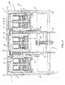
- the control mechanism 5 comprises a supporting frame 51 fixed to the outer casing 2 to provide support to movable members of the control mechanism.
- the supporting frame 51 comprises shaped lateral portions 51A that are spaced one to another.
- the lateral portions 51A may be formed by suitably shaped metal plates.
- the supporting frame 51 comprises one or more transversal portions 51B positioned between the lateral portions 51A and mechanically connected to these latter to increase the overall mechanical rigidity of the supporting frame.
- the transversal portions 51B may be formed by suitable tie rods or pins (as shown in figures 1-9 ) or by suitably shaped metal plates (as shown in figures 10 ).
- the supporting frame 5 comprises supporting frame portions 510 arranged to pass through the front portion 22 of the outer casing 2 at suitable first openings (not shown) of said front portion.
- the supporting frame portions 510 protrude at least partially within the first internal volume portion 101 where the contact shaft is positioned.
- the supporting frame portions 510 are formed by first shaped protrusions of the lateral portions 51A of the supporting frame 51.
- the supporting frame 51 comprises fastening portions 511 adapted to allow the mechanical connection of the supporting frame 51 with the outer casing 2.
- the fastening portions 511 are formed by second shaped protrusions of the lateral portions 51A of the supporting frame 51.
- the switching device 1 comprises third fastening means 150 for the mechanical coupling of the outer casing 2 with the supporting frame 5 at the fastening portions 511.
- the fastening means 150 may be of known type, such as screws, bolts or tie-rods.
- the control mechanism 5 comprises one or more connecting rods 52 adapted to provide a force to move the contact shaft 4 during a switching operation of the switching device.
- the connecting rods 52 are arranged to pass through the front portion 22 of the outer casing 2 at suitable second openings (not shown) of said front portion. In this way, the connecting rods 52 protrude at least partially within the first internal volume portion 101 where the contact shaft is positioned.
- the connecting rods 52 are operatively connected to one or more actuating members 53 of the control mechanism, which are configured to suitably actuate the connecting rods 51.
- control mechanism 5 comprises an actuating shaft 55 operatively connected to the actuating members 53 of the control mechanism, which can be actuated by an actuating device for operating the switching device 1.
- control mechanism 5 comprises an actuating lever 54 operatively connected to the actuating members 53 of the control mechanism, which can be manually actuated by a user for operating the switching device 1.
- control mechanism 5 comprises a loading lever 550 for actuating the actuating shaft 55.
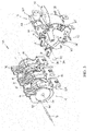
- the switching device 1 comprises one or more coupling elements 61 adapted to support the contact haft 4 and provide a mechanical connection between the control mechanism 5 and the contact shaft 4.
- each coupling element 61 is at least partially accommodated in a corresponding coupling recess 45 of the contact shaft 4.
- each coupling recess 45 is arranged between a pair of adjacent contact seats 41 of the contact shaft 4.
- each coupling element 61 comprises a first coupling point 611, at which said coupling element is fixed to the contact shaft 4.
- the coupling elements 61 provide support to the said contact shaft 4 and maintain it in a relative position with respect to the outer casing 2.
- the coupling elements 61 maintain the contact shaft 4 in a suspended position within the first internal volume portion 101, so that the contact shaft 4 is free to rotate about the rotation axis 400.
- the coupling elements 61 comprise first coupling seats 611A (e.g. formed by through holes) at the first coupling points 611 ( figure 4 ).
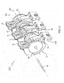
- the contact shaft 4 comprises one or more fixing points 40, at which the coupling elements 61 are fixed to the contact shaft 4 at the first coupling points 611 ( figure 9 ).
- the first coupling points 611 of the coupling elements 611 and the corresponding fixing points 40 of the contact shaft 4 are aligned along a fixing axis 40A, which is substantially parallel to the rotation axis 400 and spaced from this latter.
- the fixing axis 40A is positioned in an eccentric position with respect to a transversal section of the contact shaft 40, which is perpendicular to the rotation axis 400.
- the position of the fixing axis 40A may be suitably designed to facilitate the mounting of the contact shaft 4.
- the contact shaft 4 may be mounted/removed as a whole without intervening on the mobile contacts 31 operatively connected with the contact shaft at the rotation axis 400 (i.e. along a fixing axis different from the fixing axis 40A).
- the switching device 1 comprises fixing means 46 to fix the coupling elements 61 to the contact shaft 4.
- the fixing means 46 may comprise an elongated fixing pin that is inserted in a fixing cavity 460 of the contact shaft 4, which extends longitudinally along the fixing axis 40A. At the fixing points 40 of the contact shaft 4, the fixing pin 46 passes through the first coupling seats 611A of the coupling elements 61.
- the fixing means 46 may comprise a fixing pin for each coupling element 61.
- Each fixing pin is inserted in the fixing cavity 460 and is mechanically coupled to a corresponding coupling element 61 at a first coupling seat 611A thereof.
- each coupling element 61 comprises also a second coupling point 612 (spaced from the coupling point 611), at which said coupling element is hinged with a corresponding supporting frame portion 510 of the supporting frame 51 of the control mechanism 5.
- the coupling elements 61 provide a centre of rotation for the contact shaft 4 about the rotation axis 400.
- the coupling elements 61 fix the position of the rotation axis 400 of the contact shaft 4 within the first internal volume portion 101 at the second coupling points 612 that are spaced from the first coupling points 611.
- the coupling elements 61 rotate solidly with the contact shaft 4 about the rotation axis 400 at the rotation centres formed by the second coupling points 612.
- the coupling elements 61 are positioned in a first operating position corresponding to a coupling position of the electric contacts 31, 32 (the switching device is in a closing state).
- the coupling elements 61 are positioned in a second operating position corresponding to a coupling position of the electric contacts 31, 32 (the switching device is in a opening state).
- the coupling elements 61 rotate about the rotation axis 400 together with the contact shaft 4 and the mobile contacts 31, respectively according to a rotation direction R1 or a rotation direction R2 mutually opposite one to another.
- the coupling elements 61 comprise second coupling seats 612A (e.g. formed by through holes) at the second coupling points 612 ( figure 4 ).
- the supporting frame portions 510 comprise one or more first hinging points 510A, at which the coupling elements 61 are hinged to the supporting frame 5 at the second coupling points 612 ( figure 10 ).
- the second coupling points 612 of the coupling elements 61 and the corresponding first hinging points 510A of the supporting frame portions 510 are aligned along a same first hinging axis that coincides with the rotation axis 400 of the contact shaft.
- the supporting frame portions 510 comprise one or more first hinging seats 510B (e.g. formed by through holes) at the first hinging points 510A ( figure 10 ).
- first hinging seats 510B e.g. formed by through holes
- the switching device 1 comprises first hinging means 56 to hinge the coupling elements 61 with corresponding supporting frame portions 510.
- the first hinging means 56 may comprise one or more first hinging pins, each of which passes through the second coupling seat 612A of a coupling element 61 and the first hinging seat 510B of a corresponding supporting frame portion.
- the fixing means 56 may comprise a single elongated pin passing through the second coupling seats 612A of the coupling elements 61 and the first hinging seats 510B of the supporting frame portions 510.
- each coupling element 61 comprises also a third coupling point 613 (spaced from the coupling points 611, 612), at which said coupling element is hinged with a corresponding connecting rod 52 of the control mechanism 5.
- the coupling elements 61 are subject to a force F exerted by the connecting rods 52 to rotate said coupling elements and the contact shaft 4 about the rotation axis 400, during a switching operation of the switching device.
- the direction of the force F exerted by the connecting rods 52 depends on whether the switching device 1 is performing an opening manoeuvre or a closing manoeuvre.
- the coupling elements 61 are capable to transform a translation force F exerted by the connecting rods 52 in a rotational force transmitted to the mobile contact assembly 314.
- the coupling elements 61 comprise third coupling seats 613A (e.g. formed by through holes) at the third coupling points 613 ( figure 4 ).
- third coupling seats 613A e.g. formed by through holes
- the connecting rods 52 comprise one or more second hinging points 52A at which the coupling elements 61 are hinged to said connecting rods at the third coupling points 613 ( figure 10 ).
- the third coupling points 613 of the coupling elements 61 and the corresponding second hinging points 52A of the connecting rods 52 are aligned along a second hinging axis 520 parallel with the rotation axis 400 and spaced from this latter.
- the distance between the axes 520, 400 may be selected as a function to the force to be transmitted to the mobile contact assembly 314.
- the connecting rods 52 comprise one or more second hinging seats 52B (e.g. formed by through holes) at the hinging points 52A ( figure 10 ).
- second hinging seats 52B e.g. formed by through holes
- the switching device 1 comprises second hinging means 57 to hinge the coupling elements 61 with corresponding connecting rods 52.
- the second hinging means 57 comprise one or more second hinging pins, each of which passes through the third coupling seat 613A of a coupling element 61 and the second hinging seat 52B of a corresponding connecting rod 52.
- the fixing means 57 may comprise a single elongated pin passing through the third coupling seats 613A of the coupling elements 61 and the second hinging seats 52B of the connecting rods 52.
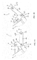
- each coupling element 61 is configured as a lever (namely a lever of the first type with intermediate fulcrum), in which the first coupling point 611 is the point of the lever on which a mechanical load (the mobile contact assembly 314) is applied, the second coupling point 612 is the fulcrum point of the lever and the third coupling point 613 is the point of the lever on which a force (the force F exerted by the connecting rods 52) is applied.
- each coupling element 61 comprises at least a supporting portion 614 fixed with the contact shaft 4 at the first coupling point 611 and hinged with a corresponding supporting frame portion 510 at the second coupling point 612 ( figure 4 ).
- each coupling element 61 comprises at least a driving portion 615 hinged with a corresponding supporting frame portion 510 at the second coupling point 612 and with a corresponding connecting rod 52 at the third coupling point 613 ( figure 4 ).
- the supporting portion 614 of the coupling elements 61 may be suitably designed to optimize the mechanical support of the contact shaft 4, e.g. as a function of the size and weight of this latter, whereas the driving portion 615 of the coupling elements 61 may be suitably designed to optimize the actuation of the contact shaft 4, e.g. as a function of the size and weight of this latter and of force provided by the control mechanism 5.
- Both the supporting and driving portions 614, 615 may be suitably designed for reducing the overall size and improving the overall structural integration.
- each coupling element 61 is formed by at least a shaped plate comprising a supporting leg 614 and a driving leg 615, which form the above mentioned supporting portion and driving portion, respectively.
- said at least a shaped plate is configured to operate as a lever of the first kind with intermediate fulcrum.
- said at least a shaped plate is L-shaped.
- each coupling element 61 is formed by a pair of L-shaped plates mutually joined and parallel one to another ( figures 1-9 ).
- said L-shaped plates are joined at the coupling points 611, 612, 613 by means of the fixing means 46 and the hinging means 56, 57 described above.
- each coupling element 61 is formed by a single L-shaped plate.
- the supporting leg 614 of a L-shaped plate extends between the first and second coupling points 611, 612 whereas the driving leg 615 of a L-shaped plate extends between the second and third coupling points 612, 613.
- the supporting leg 614 and the driving leg 615 of a L-shaped plate are coplanar and extend along extension directions D1, D2 crossing at the second coupling point 612 ( figures 4-5 ).
- the extension directions D1, D2 form an angle equal or larger than 90° at the second coupling point 612.
- the supporting leg 614 is longer than the driving leg 615.
- each coupling recess 45 of the contact shaft 4 comprises a fixing cavity 450, in which the supporting leg 614 of a corresponding L-shaped plate is inserted.
- each coupling recess 45 comprises a first abutting surface 451, to which the driving leg 615 of a corresponding L-shaped plat abuts at least partially.
- each coupling recess 45 comprises a second abutting surface 452, to which a corresponding supporting frame portion 510 abuts at least partially.
- the switching device allows achieving the intended aim and objects.
- the switching device is characterised by a high mechanical efficiency of the moving parts in particular of the mobile contact assembly 314.
- the coupling elements 61 in fact, improve the robustness and stability of the mobile contact assembly 314.
- the switching device has a compact internal structure with a limited number of components.
- the coupling elements 61 in fact, remarkably simplify the positioning of the contact shaft 4 without intervening on the mobile contacts 31.
- the switching device is thus easier to manufacture and assembly at industrial level with respect to traditional switching devices.
- the switching device is therefore characterized by lower operating costs with respect to currently available switching devices of the traditional type.
- the switching device according to the invention, provides high performances during the switching operations.
- the coupling elements 61 ensure an improved control of the movements of the mobile contact assembly 314 and a high precision of rotation of the contact shaft 4, thereby reducing the occurrence of friction and wear phenomena.
Landscapes
- Switch Cases, Indication, And Locking (AREA)
- Driving Mechanisms And Operating Circuits Of Arc-Extinguishing High-Tension Switches (AREA)
Priority Applications (6)
| Application Number | Priority Date | Filing Date | Title |
|---|---|---|---|
| EP16150771.0A EP3190600B1 (de) | 2016-01-11 | 2016-01-11 | Schaltvorrichtung mit aufgehängter mobilkontaktanordnung |
| ES16150771T ES2923788T3 (es) | 2016-01-11 | 2016-01-11 | Dispositivo de conmutación con un conjunto de contactos móviles suspendido |
| CA2953095A CA2953095C (en) | 2016-01-11 | 2016-12-28 | A switching device with a suspended mobile contact assembly |
| CN201710013947.XA CN106960740B (zh) | 2016-01-11 | 2017-01-10 | 具有悬浮式活动触头组件的开关装置 |
| US15/402,999 US10242822B2 (en) | 2016-01-11 | 2017-01-10 | Switching device with a suspended mobile contact assembly |
| BR102017000599-2A BR102017000599B1 (pt) | 2016-01-11 | 2017-01-11 | Dispositivo de comutação com um conjunto de contato móvel suspenso |
Applications Claiming Priority (1)
| Application Number | Priority Date | Filing Date | Title |
|---|---|---|---|
| EP16150771.0A EP3190600B1 (de) | 2016-01-11 | 2016-01-11 | Schaltvorrichtung mit aufgehängter mobilkontaktanordnung |
Publications (2)
| Publication Number | Publication Date |
|---|---|
| EP3190600A1 true EP3190600A1 (de) | 2017-07-12 |
| EP3190600B1 EP3190600B1 (de) | 2022-05-04 |
Family
ID=55077459
Family Applications (1)
| Application Number | Title | Priority Date | Filing Date |
|---|---|---|---|
| EP16150771.0A Active EP3190600B1 (de) | 2016-01-11 | 2016-01-11 | Schaltvorrichtung mit aufgehängter mobilkontaktanordnung |
Country Status (5)
| Country | Link |
|---|---|
| US (1) | US10242822B2 (de) |
| EP (1) | EP3190600B1 (de) |
| CN (1) | CN106960740B (de) |
| CA (1) | CA2953095C (de) |
| ES (1) | ES2923788T3 (de) |
Cited By (1)
| Publication number | Priority date | Publication date | Assignee | Title |
|---|---|---|---|---|
| EP3557604A1 (de) | 2018-04-20 | 2019-10-23 | ABB S.p.A. | Niederspannungsschaltvorrichtung |
Families Citing this family (4)
| Publication number | Priority date | Publication date | Assignee | Title |
|---|---|---|---|---|
| USD245721S (en) * | 1976-03-15 | 1977-09-06 | Koch Bernard C | Golf club head |
| USD884657S1 (en) * | 2018-04-18 | 2020-05-19 | Abb S.P.A. | Circuit breaker |
| EP3624161A1 (de) * | 2018-09-17 | 2020-03-18 | Microelettrica Scientifica S.p.A. | Elektrisch gesteuerter schalter für hochstrom-schaltvorgänge mit unterschiedlichen konfigurationen von festen klemmkontakten |
| US11972914B2 (en) * | 2020-02-07 | 2024-04-30 | Abb Schweiz Ag | Disconnector for switchgear |
Citations (4)
| Publication number | Priority date | Publication date | Assignee | Title |
|---|---|---|---|---|
| EP1003192A2 (de) * | 1998-11-20 | 2000-05-24 | General Electric Company | Antriebvorrichtung für Leistungschutzschalter mit Drehkontaktanordnung |
| EP1194941A2 (de) * | 2000-03-16 | 2002-04-10 | General Electric Company | Rückstellfeder für betätigungsmechanismus eines leistungsschalters |
| US20020153978A1 (en) * | 2001-04-19 | 2002-10-24 | Greenberg Randall Lee | Four-pole molded case circuit breaker having staggered contact depression |
| WO2006120149A1 (en) | 2005-05-13 | 2006-11-16 | Abb Service S.R.L. | Circuitbreaker with suspended mobile contact assembly |
Family Cites Families (4)
| Publication number | Priority date | Publication date | Assignee | Title |
|---|---|---|---|---|
| US2218374A (en) * | 1936-12-17 | 1940-10-15 | Gen Electric | Circuit breaker |
| US6114641A (en) * | 1998-05-29 | 2000-09-05 | General Electric Company | Rotary contact assembly for high ampere-rated circuit breakers |
| GB0003390D0 (en) | 2000-02-14 | 2000-04-05 | Roon Mark Van | Synthetic security |
| ITBG20050025A1 (it) * | 2005-05-13 | 2006-11-14 | Abb Service Srl | Interruttore con migliorate caratteristiche di intercambiabilita' del comando. |
-
2016
- 2016-01-11 EP EP16150771.0A patent/EP3190600B1/de active Active
- 2016-01-11 ES ES16150771T patent/ES2923788T3/es active Active
- 2016-12-28 CA CA2953095A patent/CA2953095C/en active Active
-
2017
- 2017-01-10 CN CN201710013947.XA patent/CN106960740B/zh active Active
- 2017-01-10 US US15/402,999 patent/US10242822B2/en active Active
Patent Citations (4)
| Publication number | Priority date | Publication date | Assignee | Title |
|---|---|---|---|---|
| EP1003192A2 (de) * | 1998-11-20 | 2000-05-24 | General Electric Company | Antriebvorrichtung für Leistungschutzschalter mit Drehkontaktanordnung |
| EP1194941A2 (de) * | 2000-03-16 | 2002-04-10 | General Electric Company | Rückstellfeder für betätigungsmechanismus eines leistungsschalters |
| US20020153978A1 (en) * | 2001-04-19 | 2002-10-24 | Greenberg Randall Lee | Four-pole molded case circuit breaker having staggered contact depression |
| WO2006120149A1 (en) | 2005-05-13 | 2006-11-16 | Abb Service S.R.L. | Circuitbreaker with suspended mobile contact assembly |
Cited By (2)
| Publication number | Priority date | Publication date | Assignee | Title |
|---|---|---|---|---|
| EP3557604A1 (de) | 2018-04-20 | 2019-10-23 | ABB S.p.A. | Niederspannungsschaltvorrichtung |
| WO2019201992A1 (en) | 2018-04-20 | 2019-10-24 | Abb S.P.A. | A low voltage switching device. |
Also Published As
| Publication number | Publication date |
|---|---|
| EP3190600B1 (de) | 2022-05-04 |
| BR102017000599A2 (pt) | 2017-07-18 |
| US10242822B2 (en) | 2019-03-26 |
| CN106960740A (zh) | 2017-07-18 |
| CN106960740B (zh) | 2020-04-10 |
| CA2953095C (en) | 2023-09-26 |
| US20170200574A1 (en) | 2017-07-13 |
| ES2923788T3 (es) | 2022-09-30 |
| CA2953095A1 (en) | 2017-07-11 |
Similar Documents
| Publication | Publication Date | Title |
|---|---|---|
| CA2953095C (en) | A switching device with a suspended mobile contact assembly | |
| RU2615742C2 (ru) | Электрическое переключающее устройство и связанный с ним электрический аппарат | |
| US9953780B2 (en) | Embedded-pole HV electrical apparatus combination switchgear | |
| US7361857B2 (en) | External operating handle mechanism for mold cased circuit breaker | |
| AU2008216975B2 (en) | Operating mechanism with adjustment of contact force | |
| CN108281320B (zh) | 用于气体绝缘开关设备的3路切断器与接地开关 | |
| EP2905853A1 (de) | Herausnehmbare Schaltanlagenvorrichtung | |
| CN104425138A (zh) | 用于电气开关的转子 | |
| RU2660912C2 (ru) | Автоматический выключатель в литом корпусе и способ его сборки | |
| KR101124493B1 (ko) | 배전반의 접지스위치 | |
| RU2368974C2 (ru) | Заземляющий переключатель | |
| CN104733224A (zh) | 电力供应系统的开关装置 | |
| US7683281B2 (en) | Circuit breaker with suspended mobile contact assembly | |
| CN104737259B (zh) | 用于开关设备的电组件和相关的开关设备 | |
| US11430622B2 (en) | Interrupter assembly | |
| KR102476858B1 (ko) | Pma 조작이 가능한 부하 개폐기 | |
| CN202695270U (zh) | 真空开闭器 | |
| EP1965476A1 (de) | Kombinierte Schutzschalter- und Trennschaltermontage in einer fest installierten elektrischen Schaltanlage | |
| CN115148514B (zh) | 开关装置 | |
| CN220121737U (zh) | 三工位开关、断路器及断路器柜 | |
| US11764551B2 (en) | Multipolar electrical protection system and electrical installation comprising such a system | |
| KR200468495Y1 (ko) | 링 메인 유닛용 주 회로 차단 장치 | |
| KR20110075544A (ko) | 가스절연개폐장치의 접지개폐기 | |
| CN110444436A (zh) | 一种接地开关 | |
| CA2891372C (en) | Structure for limiting back-travel of interrupters on circuit breakers |
Legal Events
| Date | Code | Title | Description |
|---|---|---|---|
| PUAI | Public reference made under article 153(3) epc to a published international application that has entered the european phase |
Free format text: ORIGINAL CODE: 0009012 |
|
| STAA | Information on the status of an ep patent application or granted ep patent |
Free format text: STATUS: THE APPLICATION HAS BEEN PUBLISHED |
|
| AK | Designated contracting states |
Kind code of ref document: A1 Designated state(s): AL AT BE BG CH CY CZ DE DK EE ES FI FR GB GR HR HU IE IS IT LI LT LU LV MC MK MT NL NO PL PT RO RS SE SI SK SM TR |
|
| AX | Request for extension of the european patent |
Extension state: BA ME |
|
| STAA | Information on the status of an ep patent application or granted ep patent |
Free format text: STATUS: REQUEST FOR EXAMINATION WAS MADE |
|
| 17P | Request for examination filed |
Effective date: 20171215 |
|
| RBV | Designated contracting states (corrected) |
Designated state(s): AL AT BE BG CH CY CZ DE DK EE ES FI FR GB GR HR HU IE IS IT LI LT LU LV MC MK MT NL NO PL PT RO RS SE SI SK SM TR |
|
| STAA | Information on the status of an ep patent application or granted ep patent |
Free format text: STATUS: EXAMINATION IS IN PROGRESS |
|
| 17Q | First examination report despatched |
Effective date: 20200605 |
|
| GRAP | Despatch of communication of intention to grant a patent |
Free format text: ORIGINAL CODE: EPIDOSNIGR1 |
|
| STAA | Information on the status of an ep patent application or granted ep patent |
Free format text: STATUS: GRANT OF PATENT IS INTENDED |
|
| INTG | Intention to grant announced |
Effective date: 20211221 |
|
| GRAS | Grant fee paid |
Free format text: ORIGINAL CODE: EPIDOSNIGR3 |
|
| GRAA | (expected) grant |
Free format text: ORIGINAL CODE: 0009210 |
|
| STAA | Information on the status of an ep patent application or granted ep patent |
Free format text: STATUS: THE PATENT HAS BEEN GRANTED |
|
| AK | Designated contracting states |
Kind code of ref document: B1 Designated state(s): AL AT BE BG CH CY CZ DE DK EE ES FI FR GB GR HR HU IE IS IT LI LT LU LV MC MK MT NL NO PL PT RO RS SE SI SK SM TR |
|
| REG | Reference to a national code |
Ref country code: GB Ref legal event code: FG4D |
|
| REG | Reference to a national code |
Ref country code: CH Ref legal event code: EP |
|
| REG | Reference to a national code |
Ref country code: AT Ref legal event code: REF Ref document number: 1490009 Country of ref document: AT Kind code of ref document: T Effective date: 20220515 |
|
| REG | Reference to a national code |
Ref country code: DE Ref legal event code: R096 Ref document number: 602016071653 Country of ref document: DE |
|
| REG | Reference to a national code |
Ref country code: IE Ref legal event code: FG4D |
|
| REG | Reference to a national code |
Ref country code: LT Ref legal event code: MG9D |
|
| REG | Reference to a national code |
Ref country code: NL Ref legal event code: MP Effective date: 20220504 |
|
| REG | Reference to a national code |
Ref country code: ES Ref legal event code: FG2A Ref document number: 2923788 Country of ref document: ES Kind code of ref document: T3 Effective date: 20220930 |
|
| REG | Reference to a national code |
Ref country code: AT Ref legal event code: MK05 Ref document number: 1490009 Country of ref document: AT Kind code of ref document: T Effective date: 20220504 |
|
| PG25 | Lapsed in a contracting state [announced via postgrant information from national office to epo] |
Ref country code: SE Free format text: LAPSE BECAUSE OF FAILURE TO SUBMIT A TRANSLATION OF THE DESCRIPTION OR TO PAY THE FEE WITHIN THE PRESCRIBED TIME-LIMIT Effective date: 20220504 Ref country code: PT Free format text: LAPSE BECAUSE OF FAILURE TO SUBMIT A TRANSLATION OF THE DESCRIPTION OR TO PAY THE FEE WITHIN THE PRESCRIBED TIME-LIMIT Effective date: 20220905 Ref country code: NO Free format text: LAPSE BECAUSE OF FAILURE TO SUBMIT A TRANSLATION OF THE DESCRIPTION OR TO PAY THE FEE WITHIN THE PRESCRIBED TIME-LIMIT Effective date: 20220804 Ref country code: NL Free format text: LAPSE BECAUSE OF FAILURE TO SUBMIT A TRANSLATION OF THE DESCRIPTION OR TO PAY THE FEE WITHIN THE PRESCRIBED TIME-LIMIT Effective date: 20220504 Ref country code: LT Free format text: LAPSE BECAUSE OF FAILURE TO SUBMIT A TRANSLATION OF THE DESCRIPTION OR TO PAY THE FEE WITHIN THE PRESCRIBED TIME-LIMIT Effective date: 20220504 Ref country code: HR Free format text: LAPSE BECAUSE OF FAILURE TO SUBMIT A TRANSLATION OF THE DESCRIPTION OR TO PAY THE FEE WITHIN THE PRESCRIBED TIME-LIMIT Effective date: 20220504 Ref country code: GR Free format text: LAPSE BECAUSE OF FAILURE TO SUBMIT A TRANSLATION OF THE DESCRIPTION OR TO PAY THE FEE WITHIN THE PRESCRIBED TIME-LIMIT Effective date: 20220805 Ref country code: FI Free format text: LAPSE BECAUSE OF FAILURE TO SUBMIT A TRANSLATION OF THE DESCRIPTION OR TO PAY THE FEE WITHIN THE PRESCRIBED TIME-LIMIT Effective date: 20220504 Ref country code: BG Free format text: LAPSE BECAUSE OF FAILURE TO SUBMIT A TRANSLATION OF THE DESCRIPTION OR TO PAY THE FEE WITHIN THE PRESCRIBED TIME-LIMIT Effective date: 20220804 Ref country code: AT Free format text: LAPSE BECAUSE OF FAILURE TO SUBMIT A TRANSLATION OF THE DESCRIPTION OR TO PAY THE FEE WITHIN THE PRESCRIBED TIME-LIMIT Effective date: 20220504 |
|
| PG25 | Lapsed in a contracting state [announced via postgrant information from national office to epo] |
Ref country code: RS Free format text: LAPSE BECAUSE OF FAILURE TO SUBMIT A TRANSLATION OF THE DESCRIPTION OR TO PAY THE FEE WITHIN THE PRESCRIBED TIME-LIMIT Effective date: 20220504 Ref country code: PL Free format text: LAPSE BECAUSE OF FAILURE TO SUBMIT A TRANSLATION OF THE DESCRIPTION OR TO PAY THE FEE WITHIN THE PRESCRIBED TIME-LIMIT Effective date: 20220504 Ref country code: LV Free format text: LAPSE BECAUSE OF FAILURE TO SUBMIT A TRANSLATION OF THE DESCRIPTION OR TO PAY THE FEE WITHIN THE PRESCRIBED TIME-LIMIT Effective date: 20220504 Ref country code: IS Free format text: LAPSE BECAUSE OF FAILURE TO SUBMIT A TRANSLATION OF THE DESCRIPTION OR TO PAY THE FEE WITHIN THE PRESCRIBED TIME-LIMIT Effective date: 20220904 |
|
| PG25 | Lapsed in a contracting state [announced via postgrant information from national office to epo] |
Ref country code: SM Free format text: LAPSE BECAUSE OF FAILURE TO SUBMIT A TRANSLATION OF THE DESCRIPTION OR TO PAY THE FEE WITHIN THE PRESCRIBED TIME-LIMIT Effective date: 20220504 Ref country code: SK Free format text: LAPSE BECAUSE OF FAILURE TO SUBMIT A TRANSLATION OF THE DESCRIPTION OR TO PAY THE FEE WITHIN THE PRESCRIBED TIME-LIMIT Effective date: 20220504 Ref country code: RO Free format text: LAPSE BECAUSE OF FAILURE TO SUBMIT A TRANSLATION OF THE DESCRIPTION OR TO PAY THE FEE WITHIN THE PRESCRIBED TIME-LIMIT Effective date: 20220504 Ref country code: EE Free format text: LAPSE BECAUSE OF FAILURE TO SUBMIT A TRANSLATION OF THE DESCRIPTION OR TO PAY THE FEE WITHIN THE PRESCRIBED TIME-LIMIT Effective date: 20220504 Ref country code: DK Free format text: LAPSE BECAUSE OF FAILURE TO SUBMIT A TRANSLATION OF THE DESCRIPTION OR TO PAY THE FEE WITHIN THE PRESCRIBED TIME-LIMIT Effective date: 20220504 Ref country code: CZ Free format text: LAPSE BECAUSE OF FAILURE TO SUBMIT A TRANSLATION OF THE DESCRIPTION OR TO PAY THE FEE WITHIN THE PRESCRIBED TIME-LIMIT Effective date: 20220504 |
|
| REG | Reference to a national code |
Ref country code: DE Ref legal event code: R097 Ref document number: 602016071653 Country of ref document: DE |
|
| PLBE | No opposition filed within time limit |
Free format text: ORIGINAL CODE: 0009261 |
|
| STAA | Information on the status of an ep patent application or granted ep patent |
Free format text: STATUS: NO OPPOSITION FILED WITHIN TIME LIMIT |
|
| PG25 | Lapsed in a contracting state [announced via postgrant information from national office to epo] |
Ref country code: AL Free format text: LAPSE BECAUSE OF FAILURE TO SUBMIT A TRANSLATION OF THE DESCRIPTION OR TO PAY THE FEE WITHIN THE PRESCRIBED TIME-LIMIT Effective date: 20220504 |
|
| 26N | No opposition filed |
Effective date: 20230207 |
|
| PG25 | Lapsed in a contracting state [announced via postgrant information from national office to epo] |
Ref country code: SI Free format text: LAPSE BECAUSE OF FAILURE TO SUBMIT A TRANSLATION OF THE DESCRIPTION OR TO PAY THE FEE WITHIN THE PRESCRIBED TIME-LIMIT Effective date: 20220504 |
|
| REG | Reference to a national code |
Ref country code: CH Ref legal event code: PL |
|
| GBPC | Gb: european patent ceased through non-payment of renewal fee |
Effective date: 20230111 |
|
| PG25 | Lapsed in a contracting state [announced via postgrant information from national office to epo] |
Ref country code: LU Free format text: LAPSE BECAUSE OF NON-PAYMENT OF DUE FEES Effective date: 20230111 |
|
| REG | Reference to a national code |
Ref country code: BE Ref legal event code: MM Effective date: 20230131 |
|
| PG25 | Lapsed in a contracting state [announced via postgrant information from national office to epo] |
Ref country code: LI Free format text: LAPSE BECAUSE OF NON-PAYMENT OF DUE FEES Effective date: 20230131 Ref country code: GB Free format text: LAPSE BECAUSE OF NON-PAYMENT OF DUE FEES Effective date: 20230111 Ref country code: CH Free format text: LAPSE BECAUSE OF NON-PAYMENT OF DUE FEES Effective date: 20230131 |
|
| PG25 | Lapsed in a contracting state [announced via postgrant information from national office to epo] |
Ref country code: BE Free format text: LAPSE BECAUSE OF NON-PAYMENT OF DUE FEES Effective date: 20230131 |
|
| PG25 | Lapsed in a contracting state [announced via postgrant information from national office to epo] |
Ref country code: IE Free format text: LAPSE BECAUSE OF NON-PAYMENT OF DUE FEES Effective date: 20230111 |
|
| PG25 | Lapsed in a contracting state [announced via postgrant information from national office to epo] |
Ref country code: MC Free format text: LAPSE BECAUSE OF FAILURE TO SUBMIT A TRANSLATION OF THE DESCRIPTION OR TO PAY THE FEE WITHIN THE PRESCRIBED TIME-LIMIT Effective date: 20220504 |
|
| PG25 | Lapsed in a contracting state [announced via postgrant information from national office to epo] |
Ref country code: MC Free format text: LAPSE BECAUSE OF FAILURE TO SUBMIT A TRANSLATION OF THE DESCRIPTION OR TO PAY THE FEE WITHIN THE PRESCRIBED TIME-LIMIT Effective date: 20220504 |
|
| PG25 | Lapsed in a contracting state [announced via postgrant information from national office to epo] |
Ref country code: BG Free format text: LAPSE BECAUSE OF FAILURE TO SUBMIT A TRANSLATION OF THE DESCRIPTION OR TO PAY THE FEE WITHIN THE PRESCRIBED TIME-LIMIT Effective date: 20220504 |
|
| PG25 | Lapsed in a contracting state [announced via postgrant information from national office to epo] |
Ref country code: BG Free format text: LAPSE BECAUSE OF FAILURE TO SUBMIT A TRANSLATION OF THE DESCRIPTION OR TO PAY THE FEE WITHIN THE PRESCRIBED TIME-LIMIT Effective date: 20220504 |
|
| PG25 | Lapsed in a contracting state [announced via postgrant information from national office to epo] |
Ref country code: CY Free format text: LAPSE BECAUSE OF FAILURE TO SUBMIT A TRANSLATION OF THE DESCRIPTION OR TO PAY THE FEE WITHIN THE PRESCRIBED TIME-LIMIT; INVALID AB INITIO Effective date: 20160111 |
|
| PG25 | Lapsed in a contracting state [announced via postgrant information from national office to epo] |
Ref country code: HU Free format text: LAPSE BECAUSE OF FAILURE TO SUBMIT A TRANSLATION OF THE DESCRIPTION OR TO PAY THE FEE WITHIN THE PRESCRIBED TIME-LIMIT; INVALID AB INITIO Effective date: 20160111 |
|
| PG25 | Lapsed in a contracting state [announced via postgrant information from national office to epo] |
Ref country code: TR Free format text: LAPSE BECAUSE OF FAILURE TO SUBMIT A TRANSLATION OF THE DESCRIPTION OR TO PAY THE FEE WITHIN THE PRESCRIBED TIME-LIMIT Effective date: 20220504 |
|
| PGFP | Annual fee paid to national office [announced via postgrant information from national office to epo] |
Ref country code: ES Payment date: 20260227 Year of fee payment: 11 |
|
| PGFP | Annual fee paid to national office [announced via postgrant information from national office to epo] |
Ref country code: DE Payment date: 20260121 Year of fee payment: 11 |
|
| PGFP | Annual fee paid to national office [announced via postgrant information from national office to epo] |
Ref country code: IT Payment date: 20260126 Year of fee payment: 11 |
|
| PGFP | Annual fee paid to national office [announced via postgrant information from national office to epo] |
Ref country code: FR Payment date: 20260123 Year of fee payment: 11 |