EP3190658B1 - Véhicule à selle - Google Patents
Véhicule à selle Download PDFInfo
- Publication number
- EP3190658B1 EP3190658B1 EP15837521.2A EP15837521A EP3190658B1 EP 3190658 B1 EP3190658 B1 EP 3190658B1 EP 15837521 A EP15837521 A EP 15837521A EP 3190658 B1 EP3190658 B1 EP 3190658B1
- Authority
- EP
- European Patent Office
- Prior art keywords
- antenna
- vehicle
- seat
- disposed
- frame
- Prior art date
- Legal status (The legal status is an assumption and is not a legal conclusion. Google has not performed a legal analysis and makes no representation as to the accuracy of the status listed.)
- Not-in-force
Links
- 238000004891 communication Methods 0.000 claims description 39
- 239000000463 material Substances 0.000 claims description 17
- 230000005404 monopole Effects 0.000 claims description 6
- 239000004020 conductor Substances 0.000 description 10
- 239000002184 metal Substances 0.000 description 7
- 230000005540 biological transmission Effects 0.000 description 6
- 238000009413 insulation Methods 0.000 description 5
- 238000005452 bending Methods 0.000 description 3
- 238000010276 construction Methods 0.000 description 3
- 230000005855 radiation Effects 0.000 description 3
- XLYOFNOQVPJJNP-UHFFFAOYSA-N water Substances O XLYOFNOQVPJJNP-UHFFFAOYSA-N 0.000 description 3
- 230000000694 effects Effects 0.000 description 2
- 230000005684 electric field Effects 0.000 description 2
- 239000002828 fuel tank Substances 0.000 description 2
- 239000002649 leather substitute Substances 0.000 description 2
- 230000003014 reinforcing effect Effects 0.000 description 2
- 239000011347 resin Substances 0.000 description 2
- 229920005989 resin Polymers 0.000 description 2
- YCKRFDGAMUMZLT-UHFFFAOYSA-N Fluorine atom Chemical compound [F] YCKRFDGAMUMZLT-UHFFFAOYSA-N 0.000 description 1
- 229920005830 Polyurethane Foam Polymers 0.000 description 1
- 230000004308 accommodation Effects 0.000 description 1
- 230000007423 decrease Effects 0.000 description 1
- 238000005516 engineering process Methods 0.000 description 1
- 229910052731 fluorine Inorganic materials 0.000 description 1
- 239000011737 fluorine Substances 0.000 description 1
- 239000010985 leather Substances 0.000 description 1
- 238000000034 method Methods 0.000 description 1
- 239000004033 plastic Substances 0.000 description 1
- 229920003023 plastic Polymers 0.000 description 1
- 239000011496 polyurethane foam Substances 0.000 description 1
- 230000002265 prevention Effects 0.000 description 1
Images



Classifications
-
- B—PERFORMING OPERATIONS; TRANSPORTING
- B62—LAND VEHICLES FOR TRAVELLING OTHERWISE THAN ON RAILS
- B62J—CYCLE SADDLES OR SEATS; AUXILIARY DEVICES OR ACCESSORIES SPECIALLY ADAPTED TO CYCLES AND NOT OTHERWISE PROVIDED FOR, e.g. ARTICLE CARRIERS OR CYCLE PROTECTORS
- B62J25/00—Foot-rests; Knee grips; Passenger hand-grips
- B62J25/08—Passengers hand-grips
-
- B—PERFORMING OPERATIONS; TRANSPORTING
- B62—LAND VEHICLES FOR TRAVELLING OTHERWISE THAN ON RAILS
- B62J—CYCLE SADDLES OR SEATS; AUXILIARY DEVICES OR ACCESSORIES SPECIALLY ADAPTED TO CYCLES AND NOT OTHERWISE PROVIDED FOR, e.g. ARTICLE CARRIERS OR CYCLE PROTECTORS
- B62J1/00—Saddles or other seats for cycles; Arrangement thereof; Component parts
- B62J1/005—Saddles having a seating area with multiple separate weight bearing surfaces
-
- B—PERFORMING OPERATIONS; TRANSPORTING
- B62—LAND VEHICLES FOR TRAVELLING OTHERWISE THAN ON RAILS
- B62J—CYCLE SADDLES OR SEATS; AUXILIARY DEVICES OR ACCESSORIES SPECIALLY ADAPTED TO CYCLES AND NOT OTHERWISE PROVIDED FOR, e.g. ARTICLE CARRIERS OR CYCLE PROTECTORS
- B62J1/00—Saddles or other seats for cycles; Arrangement thereof; Component parts
- B62J1/28—Other additional equipment, e.g. back-rests for children
-
- H—ELECTRICITY
- H01—ELECTRIC ELEMENTS
- H01Q—ANTENNAS, i.e. RADIO AERIALS
- H01Q1/00—Details of, or arrangements associated with, antennas
- H01Q1/12—Supports; Mounting means
- H01Q1/22—Supports; Mounting means by structural association with other equipment or articles
-
- H—ELECTRICITY
- H01—ELECTRIC ELEMENTS
- H01Q—ANTENNAS, i.e. RADIO AERIALS
- H01Q1/00—Details of, or arrangements associated with, antennas
- H01Q1/27—Adaptation for use in or on movable bodies
- H01Q1/32—Adaptation for use in or on road or rail vehicles
-
- H—ELECTRICITY
- H01—ELECTRIC ELEMENTS
- H01Q—ANTENNAS, i.e. RADIO AERIALS
- H01Q1/00—Details of, or arrangements associated with, antennas
- H01Q1/27—Adaptation for use in or on movable bodies
- H01Q1/32—Adaptation for use in or on road or rail vehicles
- H01Q1/3208—Adaptation for use in or on road or rail vehicles characterised by the application wherein the antenna is used
- H01Q1/3233—Adaptation for use in or on road or rail vehicles characterised by the application wherein the antenna is used particular used as part of a sensor or in a security system, e.g. for automotive radar, navigation systems
-
- H—ELECTRICITY
- H01—ELECTRIC ELEMENTS
- H01Q—ANTENNAS, i.e. RADIO AERIALS
- H01Q1/00—Details of, or arrangements associated with, antennas
- H01Q1/27—Adaptation for use in or on movable bodies
- H01Q1/32—Adaptation for use in or on road or rail vehicles
- H01Q1/325—Adaptation for use in or on road or rail vehicles characterised by the location of the antenna on the vehicle
-
- H—ELECTRICITY
- H01—ELECTRIC ELEMENTS
- H01Q—ANTENNAS, i.e. RADIO AERIALS
- H01Q1/00—Details of, or arrangements associated with, antennas
- H01Q1/40—Radiating elements coated with or embedded in protective material
-
- H—ELECTRICITY
- H04—ELECTRIC COMMUNICATION TECHNIQUE
- H04B—TRANSMISSION
- H04B1/00—Details of transmission systems, not covered by a single one of groups H04B3/00 - H04B13/00; Details of transmission systems not characterised by the medium used for transmission
- H04B1/38—Transceivers, i.e. devices in which transmitter and receiver form a structural unit and in which at least one part is used for functions of transmitting and receiving
- H04B1/3822—Transceivers, i.e. devices in which transmitter and receiver form a structural unit and in which at least one part is used for functions of transmitting and receiving specially adapted for use in vehicles
Definitions
- the present invention relates to a straddled vehicle. More particularly, the present invention is directed to an antenna disposition structure.
- a straddled vehicle for communication defined in an ASV (advanced safety vehicle) with use of IT (Information Technology) has been developed as part of an advanced road traffic system.
- ASV advanced safety vehicle
- IT Information Technology
- a straddled vehicle allows road-vehicle communication with roadside communicator and vehicle-to-vehicle communication with vehicles.
- Example of the above type vehicle include one having an antenna disposed on a front side of a two-wheeled motor vehicle as the straddled vehicle for communication with a front vehicle or roadside communicator. See, for example, Patent Literature 1.
- Patent Literature 1 discloses a two-wheeled motor vehicle having an antenna with forward directivity of the two-wheeled motor vehicle disposed forward from a slant line connecting the center of a handle bar and an axle of a front wheel. This allows communication with another vehicle in front of the two-wheeled motor vehicle. In addition, another antenna with upward directivity of the two-wheeled motor vehicle is disposed forward from the antenna with the forward directivity. This allows usage of the GPS (Global Positioning System).
- GPS Global Positioning System
- Patent Literature 1 Japanese Patent Publication No. 4156783B
- the antenna with the forward directivity may cause reduction in transmitting and receiving distance in a transverse direction and a backward direction.
- the two-wheeled motor vehicle includes in a front part thereof a metal configuration such as handle bar and a head tube.
- a metal configuration such as handle bar and a head tube.
- the disposition of the non-directional antenna on a surface of the vehicle body in an erect posture may cause some damage such as bending of the antenna by tamper or a driver's body or baggage.
- antennas and vehicles including antennas are given in JP 2011-207360 A , JP 2008-114654 A , US 2006/224344 A1 , JP 2004-116261 A JP 2006-103639 A , EP 2 180 545 A1 , and US 4,658,266 A .
- the present invention has been made regarding the state of the art noted above, and its one object is to provide a straddled vehicle that allows suitable road-vehicle communication and vehicle-to-vehicle communication omnidirectionally while preventing damage to an antenna.
- the present invention is constituted as stated below to achieve the above object.
- One aspect according to claim 1 of the present invention provides a straddled vehicle comprising a non-directional antenna that performs road-vehicle communication with roadside communicator and vehicle-to-vehicle communication with a front vehicle and a rear vehicle.
- the straddled vehicle includes a seat made of a cushioning material, a seat frame that holds the seat, and the non-directional antenna is disposed backward of a front end of the seat and above the seat frame.
- the antenna is covered with the cushioning material of the seat.
- the above configuration of the aspect achieves tamper protection even when the non-directional antenna is disposed on the straddled vehicle in an erected attitude, and thus prevents damage to the antenna, such as bending of the antenna caused by a driver's body or baggage.
- the antenna is disposed above the seat frame, suitable communication is performable without affecting the electromagnetic waves transmitted/received to/from the antenna by the vehicle body.
- the antenna of the aspect of the present invention is disposed backward of the front end of the seat and above the seat frame, and thus is disposed backward of the driver on the seat. This prevents any obstructions to driving.
- the antenna is non-directional, omnidirectional communication is performable. Accordingly, the aspect is suitable to both the road-vehicle communication and the vehicle-to-vehicle communication. Such omnidirectional communication needs a single antenna, leading to enhanced reduction in cost and space.
- the antenna is covered with the cushioning material of the seat. That is, disposition of the non-directional antenna within the seat needs no additional space for the antenna, leading to reduction in space.
- the seat includes a straddled seat part and a back rest part, and that the cushioning material corresponds to a cushioning material of the back rest part.
- the non-directional antenna is disposed within the back rest part. This requires no external space for the antenna, leading to reduction in space.
- the antenna may be provided above the seat part, achieving more suitable communication.
- the aspect of the present invention further includes a passenger grip fixed on the seat frame, and that the antenna is disposed above the passenger grip.
- the antenna disposed above the passenger grip fixed on the seat frame allows prevention of influences by the passenger grip on the electromagnetic waves transmitted/received to/from the antenna.
- the antenna has a frequency band of 760 MHz.
- the antenna with the frequency band of 760 MHz achieves reduced influences on the electromagnetic waves transmitted/received to/from the antenna by the driver or a pillion passenger and achieves a sufficient amount of information transmitted and received.
- the antenna is any of a monopole antenna, a whip antenna, a collinear antenna, and a Brown antenna. Since the non-directional antenna is any of the monopole antenna, the whip antenna, the collinear antenna, and the Brown antenna, road-vehicle communication and vehicle-to-vehicle communication are suitably performable.
- the straddled vehicle with the aspect of the present invention allows suitable performance of road-vehicle communication and vehicle-to-vehicle communication omnidirectionally while avoiding damage to the antenna.
- Embodiment 1 a two-wheeled motor vehicle of a scooter type is described as one example of a straddled vehicle.
- the following description includes terms forward/backward and right/left based on a traveling direction of the two-wheeled motor vehicle.
- Fig. 1 is a side view of an outline construction of a two-wheeled motor vehicle 1 in Embodiment 1.
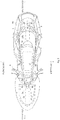
- Fig. 2 is a plan view of the outline construction of the two-wheeled motor vehicle 1.
- the two-wheeled motor vehicle 1 includes a vehicle body frame 2 of a so-called underbone type.
- the vehicle body frame 2 includes a main frame 3 and a seat frame 4.
- the main frame 3 is composed of a head tube 5, a frame main body 6, and a front frame 7.
- the main frame 3 need not include the front frame 7 depending on types of the two-wheeled motor vehicle 1.
- the vehicle body frame 2 is covered with a vehicle body cover 14 made of resin.
- the head tube 5 supports a front fork 8 via a steering shaft, not shown, such that the front fork 8 is swingable rightward/leftward. That is, the steering shaft fixed on the upper end of the front fork 8 is inserted into the head tube 5, whereby the front fork 8 is swingable rightward/leftward.
- a handle 9 is connected to an upper part of the steering shaft. Operating the handle 9 causes the front fork 8 to swing.
- a front wheel 10 is rotatably attached to a lower end of the front fork 8.
- the engine unit 11 is attached in a rear part of the main frame body 6.
- the engine unit 11 is a known unit swing-type engine that is composed of an engine 11a and a transmission case 11b extending leftward of a rear wheel 12 from the engine 11a.
- the engine 11a and the transmission case 11b are integrally suspended on the vehicle body so as to swing vertically.
- the transmission case 11b accommodates a transmission mechanism that transmits rotation of the engine to the rear wheel 12.
- a rear wheel output shaft, not shown, is disposed in a rear part of the transmission case 11b.
- the rear wheel 12 is connected to the rear wheel output shaft.
- a seat 13 is disposed above the engine 11a.
- a vehicle body cover 14 that is disposed between the engine unit 11 and the seat 13 in plan view extends backward and above the engine unit 11 in side view.
- the rear wheel 12 is disposed below the vehicle body cover 14.
- a rear part of the engine unit 11 is exposed externally.
- a fuel tank 30 is disposed forward of the engine 11a.
- the frame main body 6 includes an upper frame 6a, a lower frame 6b, and a connection bracket 6c to which rear ends of the upper and lower frames 6a and 6b are connected.
- the upper frame 6a is composed of paired right and left upper frame portions, and the portions are welded on the middle side surface in the vertical direction of the head tube 5, from which the portions extend backward apart from each other rightward and leftward.
- the lower frame 6b is composed of paired right and left lower frame portions, and the portions are welded on the lower side surface of the head tube 5, from which the portions extend backward below the upper frames 6a apart from each other rightward and leftward.
- the lower frame 6b extends upward on the rear portion thereof, and the rear end thereof is welded on the connection bracket 6c.
- Fig. 2 partially illustrates the upper frame 6a in an abbreviated manner by break lines.
- the lower frame 6b overlaps the upper frame 6a in plan view, and accordingly, a portion of the lower frame 6b in backward from the handle 9 is illustrated in an abbreviated manner.
- a reinforcing board (gazette) 15 is suspended dispersedly and is welded at a plurality of positions between the upper frame 6a and the lower frame 6b in the forward/backward direction.
- the reinforcing board 15 is made of metal, and reinforces rigidity of the upper frame 6a and the lower frame 6b.
- a pivot shaft 28 is disposed in a rear part of the connection bracket 6c for holding the engine unit 11 so as to swing vertically.
- a rear cushion unit 29 is disposed between the rear portion of the seat frame 4 and the transmission case 11b for cushion of swinging of the engine unit 11.
- the front frame 7 extends forward from the head tube 5 and the lower frame 6b.
- a battery 16 is accommodated within the front frame 7.
- An ECU 31 is disposed forward of the battery 16 in the front frame 7.
- a housing 21 is disposed above the fuel tank 30 and the engine 11a.
- the housing 21 allows accommodation of a helmet and the like.
- the seat 13 is disposed above the housing 21 and the seat frame 4.
- the seat 13 is composed of a front seat part 13a on which the driver sits, a rear seat part 13b on which a pillion passenger sits, and a front back rest part 13d and a rear back rest part 13e corresponding to the front seat part 13a and the rear seat part 13b, respectively.
- the front seat part 13a and the rear seat part 13b are integrally formed in a saddle riding form.
- the front seat part 13a and the rear seat part 13b are able to rotate about a hinge 32.
- the driver allows access to the housing 21 when the front seat part 13a and the rear seat part 13b are open.
- the rear seat part 13b is disposed backward of the front seat part 13a.
- the front back rest part 13d is disposed between the front seat part 13a and the rear seat part 13b.
- the front back rest part 13d is used for a driver's waist pad.
- the front seat part 13a and the rear seat part 13b are not necessarily formed integrally, but may be formed separately.
- a passenger grip 17 surrounds a lateral side of the rear seat part 13b.
- a front part of the passenger grip 17 is attached to a front upper end of the seat frame 4 via the bracket 18a.
- a rear part of the passenger grip 17 is attached to a rear upper end of the seat frame 4 via the bracket 18b.
- the passenger grip 17 is made of metal.
- the rear back rest part 13e is disposed backward of the rear seat part 13b, and is used as a pillion passenger's waist pad.
- the rear back rest part 13e is attached to an upper part of the passenger grip 17 via a plate 19.
- the front seat part 13a, the rear seat part 13b, the front back rest part 13d, and the rear back rest part 13e are each made of a cushioning material such as polyurethane foams.
- An exterior of the cushioning material is covered with leather, artificial leather, synthetic leather, and the like.
- a single antenna 20 is disposed within the rear back rest part 13e.
- the antenna 20 is covered with the cushioning material of the rear back rest part 13e. It is preferred that the cushioning material is hard to prevent deformation of the antenna under application of load from the pillion passenger.
- the antenna 20 is held with the plate 19. The plate 19 is attached to the passenger grip 17. Using the antenna 20 allows the two-wheeled motor vehicle 1 to perform road-vehicle communication with roadside communicator and vehicle-to-vehicle communication with other vehicles.
- the antenna 20 is disposed within the rear back rest part 13e, and thus is disposed at a level higher than a level Ho of the upper end of the seat frame 4. Moreover, the antenna 20 is disposed at a level higher than a level HI of the upper end of the passenger grip 17.
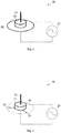
- Figs. 3 and 4 each illustrate the configuration of the antenna.
- the antenna 20 is a non-directional linear antenna.
- the non-directional linear antenna include a monopole antenna, whip antenna, a collinear antenna, and a Brown antenna.
- a Brown antenna is adopted.
- the antenna 20 includes a ground plane 22, a conductor rod 23, and an insulation member 24.
- the insulation member 24 is disposed between the ground plane 22 and the conductor rod 23.
- a power supply unit 27 supplies power to the ground plane 22 and the conductor rod 23.
- the ground plane 22 is in a disk shape. Alternatively, instead of the disk ground plane 22, three or more metal wires 26 extending radially on a plane may be adopted. See Figure 4 .
- the conductor rod 23 is a radiation conductor erected upward from the insulation member 24.
- the insulation member 24 is a plate made of a fluorine resin.
- the insulation member 24 may be made of other materials such as plastic, or may be formed by other insulating members.
- the power supply unit 27 supplies high-frequency power to the ground plane 22 or the metal wires 26 and the conductor rod 23.
- one third or less of the conductor rod 23 at a lower length overlaps the passenger grip 17 of the two-wheeled motor vehicle 1 in side view, and it is more preferred that no portion of the conductor rod 23 overlaps the passenger grip 17.
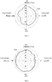
- Fig. 5 illustrates an antenna property when the non-directional antenna is disposed on a front side of the vehicle body.
- Fig. 6 illustrates an antenna property with antenna disposition of Embodiment 1.
- a direction is set under assumption that a front way of the two-wheeled motor vehicle 1 corresponds to 0 degree, a left way corresponds to 90 degrees, a back way corresponds to 180 degrees, and a right way corresponds to 270 degrees.
- an emission pattern Ep1 when the non-directional antenna is disposed in a front part of the vehicle body forward of the handle 9 has a lowered property of backward emission under influences of reflection by a metal structure such as the head tube 5 and the handle 9, leading to a shortened communication distance for backward communication.
- emission intensity falls below 60dB especially in a way of 190 to 210 degrees.
- Embodiment 1 achieves an emission pattern Ep2 illustrated in Fig. 6 .
- the emission pattern Ep2 has emission intensity not below 60dB omnidirectionally, and an omnidirectional average intensity higher than that of the emission pattern Ep1.
- a frequency band of 760 MHz is used for radio communication of the antenna 20 in Embodiment 1.
- the 760MHz band corresponds to one whose center frequency is 760MHz and whose band width is 10MHz. That is, the 760MHz band ranges from 755MHz to 765MHz.
- Using the frequency band of 760MHz achieves reduction in value of a dielectric loss angle (tan ⁇ ) by the driver and the pillion passenger relative to a frequency band higher than that (e.g., a value of a dielectric loss angle at a frequency band of 5800 MHz). This allows suppressed reduction in electric field intensity when electromagnetic waves pass through a human body.
- Fig. 7 is a graph illustrating a relative dielectric constant ( ⁇ r) and a dielectric loss angle (tan ⁇ ) of water relative to a frequency. It is assumed that the driver and the pillion passenger are composed of water. A frequency band with the smallest dielectric loss angle (tan ⁇ ) ranges from 10 to 100 MHz, the frequency band causing a small amount of information transmitted. Then, a frequency band of 100 to 1000 MHz obtains a sufficient amount of information for the road-vehicle communication and the vehicle-to-vehicle communication while increase in dielectric loss angle (tan ⁇ ) is suppressed to some extent.
- ⁇ r relative dielectric constant
- tan ⁇ dielectric loss angle
- a frequency band of 1000 MHz or more decreases the relative dielectric constant ( ⁇ r), but increases the dielectric loss angle (tan ⁇ ) and the frequency to cause significant reduction in electric field intensity when the electromagnetic waves pass through the human body.
- a frequency band of 760 MHz with a long wavelength causes a large diffraction angle (an angle at which the waves rounds behind an obstacle). Accordingly, as illustrated in Fig. 8 , electromagnetic waves Rw from the antenna 20 round an driver Ri through diffraction to propagate forward of the driver Ri.
- the antenna 20 receives electromagnetic waves from forward. Consequently, this allows vehicle-to-vehicle communication and road-vehicle communication with the antenna 20 and an object in front of the antenna regardless of presence or absence of the driver Ri.
- Embodiment 1 even when the non-directional antenna 20 is disposed on the two-wheeled motor vehicle 1 in an erected attitude, the antenna 20 is covered with the cushioning material of the rear back rest part 13e and thus is not exposed. This achieves tamper protection of the antenna 20. Moreover, this prevents damage to the antenna 20 such as by bending.
- the antenna 20 is disposed above the seat frame 4. Accordingly, suitable communication is performable with no influence of the electromagnetic waves transmitted/received to/from the antenna 20 by the vehicle body.
- the antenna 20 is moved within sight of the driver to prevent driving.
- the antenna 20 of Embodiment 1 is disposed backward of the front end 13c of the front seat part 13a and above the seat frame 4, and thus is disposed backward of the driver on the seat 13. This prevents no driving.
- the antenna 20 is non-directional, omnidirectional communication is performable. Accordingly, the embodiment is suitable to both the road-vehicle communication and the vehicle-to-vehicle communication. Such omnidirectional communication achieves a single antenna 20, leading to enhanced reduction in cost and space. Moreover, disposition of the non-directional antenna 20 within the rear back rest part 13e needs no external space for the antenna 20, leading to reduction in space. In addition, the antenna 20 is may be provided above the front seat part 13a and the rear seat part 13b, achieving more suitable communication.
- the antenna 20 that is disposed above the passenger grip 17 fixed on the seat frame 4 allows suitable communication with no influence of the electromagnetic waves transmitted/received to/from the antenna 20 by the passenger grip 17.
- the antenna 20 with the frequency band of 760 MHz achieves reduced influences by the driver or the pillion passenger to the electromagnetic waves transmitted/received to/from the antenna 20 and obtains a sufficient amount of information to be transmitted/received.
- non-directional antenna 20 is any of the monopole antenna, the whip antenna, the collinear antenna, and the Brown antenna, road-vehicle communication and vehicle-to-vehicle communication are suitably performable.
- Fig. 9 is a side view of a two-wheeled motor vehicle with antenna disposition of Embodiment 2.
- the elements denoted by the same reference numerals as in Embodiment 1 have common functions to the elements in Embodiment 1, and thus the description thereof is to be omitted.
- the configuration of the antenna other than the following is common to that in Embodiment 1.
- Embodiment 2 has the characteristic in that the antenna 20 is disposed not within the back rest part but within the seat part. In Embodiment 1, the antenna 20 is disposed within the rear back rest part 13e. In contrast to this, since Embodiment 2 provides a naked-type two-wheeled motor vehicle without any back rest, the antenna 20 is disposed within the seat part.
- the naked-type corresponds to a two-wheeled motor vehicle with an exposed engine or frame.
- the naked-type two-wheeled motor vehicle includes no passenger grip.
- the seat 13 of Embodiment 2 includes a front seat part 13a and a rear seat part 13b.
- the antenna 20 is preferably disposed in rear part of the rear seat part 13b, but may be disposed in rear part of the front seat part 13a.
- the antenna 20 is disposed backward of the front end 13c of the front seat part 13a. Accordingly, the antenna 20 is spaced away from the handle 9 by a sufficient gap. This allows propagation of electromagnetic waves from the antenna 20 forward of the handle 9 and the head tube 5 through diffraction. It is preferred that one third or less of the conductor rod 23 of the antenna 20 at its lower part overlaps the seat frame 4 of the two-wheeled motor vehicle 1 in side view, and it is more preferred that no portion of the conductor rod 23 overlaps the seat frame 4.
Landscapes
- Engineering & Computer Science (AREA)
- Mechanical Engineering (AREA)
- Remote Sensing (AREA)
- Computer Security & Cryptography (AREA)
- Radar, Positioning & Navigation (AREA)
- Computer Networks & Wireless Communication (AREA)
- Signal Processing (AREA)
- Support Of Aerials (AREA)
- Details Of Aerials (AREA)
Claims (5)
- Véhicule à selle (1), comprenant:un siège (13) réalisé en un matériau de rembourrage;un châssis de siège (4) configuré pour maintenir le siège (13); etune antenne non directionnelle (20) disposée à l'arrière d'une extrémité avant (13c) du siège (13) et au-dessus du châssis de siège (4), l'antenne (20) étant recouverte du matériau de rembourrage du siège (13),dans lequel l'antenne est configurée pour effectuer une communication route-véhicule avec un communicateur routier et une communication de véhicule à véhicule avec un véhicule avant et un véhicule arrière.
- Véhicule à selle (1) selon la revendication 1, dans lequel
le siège (13) comprend une partie de siège enfourchée (13a) et une partie de dossier (13e); et
le matériau de rembourrage correspond à un matériau de rembourrage de la partie de dossier (13e). - Véhicule à selle (1) selon la revendication 1 ou 2, comprenant par ailleurs:une poignée de passager (17) fixée au châssis de siège (4), oùl'antenne (20) est disposée au-dessus de la poignée de passager (17).
- Véhicule à selle (1) selon l'une quelconque des revendications 1 à 3, dans lequel
l'antenne (20) est configurée pour fonctionner dans une bande de fréquences présentant une fréquence centrale de 760 MHz. - Véhicule à selle (1) selon l'une quelconque des revendications 1 à 4, dans lequel
l'antenne (20) est une antenne monopôle, une antenne fouet, une antenne colinéaire et une antenne de Brown.
Applications Claiming Priority (2)
| Application Number | Priority Date | Filing Date | Title |
|---|---|---|---|
| JP2014180323 | 2014-09-04 | ||
| PCT/JP2015/074892 WO2016035797A1 (fr) | 2014-09-04 | 2015-09-01 | Véhicule à selle |
Publications (3)
| Publication Number | Publication Date |
|---|---|
| EP3190658A1 EP3190658A1 (fr) | 2017-07-12 |
| EP3190658A4 EP3190658A4 (fr) | 2017-08-23 |
| EP3190658B1 true EP3190658B1 (fr) | 2018-11-14 |
Family
ID=55439857
Family Applications (1)
| Application Number | Title | Priority Date | Filing Date |
|---|---|---|---|
| EP15837521.2A Not-in-force EP3190658B1 (fr) | 2014-09-04 | 2015-09-01 | Véhicule à selle |
Country Status (4)
| Country | Link |
|---|---|
| US (1) | US20170179583A1 (fr) |
| EP (1) | EP3190658B1 (fr) |
| JP (1) | JP6346292B2 (fr) |
| WO (1) | WO2016035797A1 (fr) |
Families Citing this family (2)
| Publication number | Priority date | Publication date | Assignee | Title |
|---|---|---|---|---|
| EP3826106B1 (fr) | 2018-08-27 | 2023-11-22 | Yamaha Hatsudoki Kabushiki Kaisha | Véhicule à inclinaison monté sur antenne de communication v2x |
| CN112739612B (zh) * | 2018-09-28 | 2022-06-14 | 本田技研工业株式会社 | 跨骑型车辆 |
Family Cites Families (18)
| Publication number | Priority date | Publication date | Assignee | Title |
|---|---|---|---|---|
| US4206409A (en) * | 1978-02-21 | 1980-06-03 | Mckinney Samuel A | Motor vehicle communication apparatus |
| US4658266A (en) * | 1983-10-13 | 1987-04-14 | Doty Archibald C Jun | Vertical antenna with improved artificial ground system |
| JP4156783B2 (ja) * | 2000-04-03 | 2008-09-24 | 本田技研工業株式会社 | 自動二輪車のアンテナ配置構造 |
| JP4173983B2 (ja) * | 2002-09-30 | 2008-10-29 | 本田技研工業株式会社 | 自動二輪車用電子キーシステム |
| JP4386818B2 (ja) * | 2004-10-07 | 2009-12-16 | 本田技研工業株式会社 | 小型車両の通信手段配置構造 |
| JP2006103639A (ja) * | 2004-10-08 | 2006-04-20 | Honda Motor Co Ltd | 小型電動車両 |
| JP2006182065A (ja) * | 2004-12-24 | 2006-07-13 | Yamaha Motor Co Ltd | 鞍乗型車両 |
| JP4849433B2 (ja) * | 2005-03-30 | 2012-01-11 | 本田技研工業株式会社 | タイヤ空気圧監視装置およびこれを備えた車両 |
| JP2008114654A (ja) * | 2006-11-01 | 2008-05-22 | Yamaha Motor Co Ltd | 自動二輪車 |
| JP4958154B2 (ja) * | 2006-11-29 | 2012-06-20 | 本田技研工業株式会社 | 自動二輪車 |
| JP2010120628A (ja) * | 2008-10-24 | 2010-06-03 | Yamaha Motor Co Ltd | 自動二輪車 |
| US8616324B2 (en) * | 2009-07-25 | 2013-12-31 | Gary D. Chipp | Sub-frame and component configuration for mounting of a motorcycle drop seat |
| JP5523892B2 (ja) * | 2010-03-30 | 2014-06-18 | 本田技研工業株式会社 | 鞍乗り型車両の方向指示器自動解除装置及び方向指示器自動解除方法 |
| JP5560082B2 (ja) * | 2010-03-31 | 2014-07-23 | 本田技研工業株式会社 | 自動二輪車の情報提供システム |
| JP5427735B2 (ja) * | 2010-08-31 | 2014-02-26 | 本田技研工業株式会社 | 鞍乗り型車両 |
| JP5596012B2 (ja) * | 2011-12-28 | 2014-09-24 | 本田技研工業株式会社 | 自動二輪車 |
| JP5782403B2 (ja) * | 2012-03-30 | 2015-09-24 | 本田技研工業株式会社 | グラブレールの配置構造 |
| JP5912877B2 (ja) * | 2012-05-31 | 2016-04-27 | 本田技研工業株式会社 | 鞍乗り型車両の補機取付構造 |
-
2015
- 2015-09-01 WO PCT/JP2015/074892 patent/WO2016035797A1/fr not_active Ceased
- 2015-09-01 EP EP15837521.2A patent/EP3190658B1/fr not_active Not-in-force
- 2015-09-01 JP JP2016546661A patent/JP6346292B2/ja not_active Expired - Fee Related
-
2017
- 2017-03-03 US US15/449,225 patent/US20170179583A1/en not_active Abandoned
Non-Patent Citations (1)
| Title |
|---|
| None * |
Also Published As
| Publication number | Publication date |
|---|---|
| US20170179583A1 (en) | 2017-06-22 |
| WO2016035797A1 (fr) | 2016-03-10 |
| JP6346292B2 (ja) | 2018-06-20 |
| JPWO2016035797A1 (ja) | 2017-07-27 |
| EP3190658A1 (fr) | 2017-07-12 |
| EP3190658A4 (fr) | 2017-08-23 |
Similar Documents
| Publication | Publication Date | Title |
|---|---|---|
| EP2965979B1 (fr) | Véhicule à moteur à deux roues | |
| US11909106B2 (en) | V2X communication antenna-mounted leaning vehicle | |
| JP5596012B2 (ja) | 自動二輪車 | |
| EP2180332B1 (fr) | Motocyclette | |
| EP3190658B1 (fr) | Véhicule à selle | |
| EP2980920B1 (fr) | Moto | |
| US11588229B2 (en) | Straddle type vehicle | |
| JP5656924B2 (ja) | 自動二輪車の盗難対策装置 | |
| JP2004179790A (ja) | 車載アンテナ装置 | |
| US20050200519A1 (en) | Saddle-type vehicle equipped with a navigation system | |
| JP2011184001A (ja) | 鞍乗り型車両 | |
| JP5470104B2 (ja) | 鞍乗り型車両 | |
| JP7191963B2 (ja) | 車車間通信用アンテナ搭載リーン車両、及びリーン車両に搭載されるように構成された車車間通信用アンテナ | |
| JP7183279B2 (ja) | 車車間通信用アンテナ搭載リーン車両、及びリーン車両に搭載されるように構成された車車間通信用アンテナ | |
| JP5192995B2 (ja) | 自動二輪車の盗難対策装置 | |
| WO2020045391A1 (fr) | Véhicule mince avec antenne de communication entre véhicules montée sur celui-ci, et antenne de communication entre véhicules configurée pour être montée sur un véhicule mince | |
| CN1944165B (zh) | 具有智能钥匙系统的骑乘型车辆 | |
| JP2012176754A (ja) | 自動二輪車の盗難対策装置 | |
| JP2020032737A (ja) | 車車間通信用アンテナ搭載リーン車両 | |
| JP2025127805A (ja) | 鞍乗り型車両 | |
| JPWO2020045390A1 (ja) | 車車間通信用アンテナ搭載リーン車両 | |
| BRPI1101117A2 (pt) | veìculo para montaria | |
| CN105363215A (zh) | 一种轻量化童车 |
Legal Events
| Date | Code | Title | Description |
|---|---|---|---|
| STAA | Information on the status of an ep patent application or granted ep patent |
Free format text: STATUS: THE INTERNATIONAL PUBLICATION HAS BEEN MADE |
|
| PUAI | Public reference made under article 153(3) epc to a published international application that has entered the european phase |
Free format text: ORIGINAL CODE: 0009012 |
|
| STAA | Information on the status of an ep patent application or granted ep patent |
Free format text: STATUS: REQUEST FOR EXAMINATION WAS MADE |
|
| 17P | Request for examination filed |
Effective date: 20170328 |
|
| AK | Designated contracting states |
Kind code of ref document: A1 Designated state(s): AL AT BE BG CH CY CZ DE DK EE ES FI FR GB GR HR HU IE IS IT LI LT LU LV MC MK MT NL NO PL PT RO RS SE SI SK SM TR |
|
| AX | Request for extension of the european patent |
Extension state: BA ME |
|
| A4 | Supplementary search report drawn up and despatched |
Effective date: 20170726 |
|
| RIC1 | Information provided on ipc code assigned before grant |
Ipc: B62J 1/28 20060101ALI20170714BHEP Ipc: B62J 1/00 20060101ALI20170714BHEP Ipc: H01Q 1/32 20060101AFI20170714BHEP Ipc: H01Q 1/40 20060101ALI20170714BHEP Ipc: H01Q 1/22 20060101ALI20170714BHEP Ipc: H04B 1/3822 20150101ALI20170714BHEP Ipc: B62J 99/00 20090101ALI20170714BHEP |
|
| DAV | Request for validation of the european patent (deleted) | ||
| DAX | Request for extension of the european patent (deleted) | ||
| GRAP | Despatch of communication of intention to grant a patent |
Free format text: ORIGINAL CODE: EPIDOSNIGR1 |
|
| STAA | Information on the status of an ep patent application or granted ep patent |
Free format text: STATUS: GRANT OF PATENT IS INTENDED |
|
| INTG | Intention to grant announced |
Effective date: 20180316 |
|
| RIN1 | Information on inventor provided before grant (corrected) |
Inventor name: HASHIMOTO, YASUSHI |
|
| INTG | Intention to grant announced |
Effective date: 20180316 |
|
| GRAS | Grant fee paid |
Free format text: ORIGINAL CODE: EPIDOSNIGR3 |
|
| GRAJ | Information related to disapproval of communication of intention to grant by the applicant or resumption of examination proceedings by the epo deleted |
Free format text: ORIGINAL CODE: EPIDOSDIGR1 |
|
| GRAL | Information related to payment of fee for publishing/printing deleted |
Free format text: ORIGINAL CODE: EPIDOSDIGR3 |
|
| STAA | Information on the status of an ep patent application or granted ep patent |
Free format text: STATUS: REQUEST FOR EXAMINATION WAS MADE |
|
| GRAR | Information related to intention to grant a patent recorded |
Free format text: ORIGINAL CODE: EPIDOSNIGR71 |
|
| STAA | Information on the status of an ep patent application or granted ep patent |
Free format text: STATUS: GRANT OF PATENT IS INTENDED |
|
| INTC | Intention to grant announced (deleted) | ||
| INTG | Intention to grant announced |
Effective date: 20180807 |
|
| GRAA | (expected) grant |
Free format text: ORIGINAL CODE: 0009210 |
|
| STAA | Information on the status of an ep patent application or granted ep patent |
Free format text: STATUS: THE PATENT HAS BEEN GRANTED |
|
| AK | Designated contracting states |
Kind code of ref document: B1 Designated state(s): AL AT BE BG CH CY CZ DE DK EE ES FI FR GB GR HR HU IE IS IT LI LT LU LV MC MK MT NL NO PL PT RO RS SE SI SK SM TR |
|
| REG | Reference to a national code |
Ref country code: CH Ref legal event code: EP Ref country code: AT Ref legal event code: REF Ref document number: 1065927 Country of ref document: AT Kind code of ref document: T Effective date: 20181115 |
|
| REG | Reference to a national code |
Ref country code: DE Ref legal event code: R096 Ref document number: 602015019898 Country of ref document: DE |
|
| REG | Reference to a national code |
Ref country code: IE Ref legal event code: FG4D |
|
| REG | Reference to a national code |
Ref country code: NL Ref legal event code: MP Effective date: 20181114 |
|
| REG | Reference to a national code |
Ref country code: LT Ref legal event code: MG4D |
|
| REG | Reference to a national code |
Ref country code: AT Ref legal event code: MK05 Ref document number: 1065927 Country of ref document: AT Kind code of ref document: T Effective date: 20181114 |
|
| PG25 | Lapsed in a contracting state [announced via postgrant information from national office to epo] |
Ref country code: BG Free format text: LAPSE BECAUSE OF FAILURE TO SUBMIT A TRANSLATION OF THE DESCRIPTION OR TO PAY THE FEE WITHIN THE PRESCRIBED TIME-LIMIT Effective date: 20190214 Ref country code: NO Free format text: LAPSE BECAUSE OF FAILURE TO SUBMIT A TRANSLATION OF THE DESCRIPTION OR TO PAY THE FEE WITHIN THE PRESCRIBED TIME-LIMIT Effective date: 20190214 Ref country code: LT Free format text: LAPSE BECAUSE OF FAILURE TO SUBMIT A TRANSLATION OF THE DESCRIPTION OR TO PAY THE FEE WITHIN THE PRESCRIBED TIME-LIMIT Effective date: 20181114 Ref country code: HR Free format text: LAPSE BECAUSE OF FAILURE TO SUBMIT A TRANSLATION OF THE DESCRIPTION OR TO PAY THE FEE WITHIN THE PRESCRIBED TIME-LIMIT Effective date: 20181114 Ref country code: LV Free format text: LAPSE BECAUSE OF FAILURE TO SUBMIT A TRANSLATION OF THE DESCRIPTION OR TO PAY THE FEE WITHIN THE PRESCRIBED TIME-LIMIT Effective date: 20181114 Ref country code: FI Free format text: LAPSE BECAUSE OF FAILURE TO SUBMIT A TRANSLATION OF THE DESCRIPTION OR TO PAY THE FEE WITHIN THE PRESCRIBED TIME-LIMIT Effective date: 20181114 Ref country code: AT Free format text: LAPSE BECAUSE OF FAILURE TO SUBMIT A TRANSLATION OF THE DESCRIPTION OR TO PAY THE FEE WITHIN THE PRESCRIBED TIME-LIMIT Effective date: 20181114 Ref country code: ES Free format text: LAPSE BECAUSE OF FAILURE TO SUBMIT A TRANSLATION OF THE DESCRIPTION OR TO PAY THE FEE WITHIN THE PRESCRIBED TIME-LIMIT Effective date: 20181114 Ref country code: IS Free format text: LAPSE BECAUSE OF FAILURE TO SUBMIT A TRANSLATION OF THE DESCRIPTION OR TO PAY THE FEE WITHIN THE PRESCRIBED TIME-LIMIT Effective date: 20190314 |
|
| PG25 | Lapsed in a contracting state [announced via postgrant information from national office to epo] |
Ref country code: GR Free format text: LAPSE BECAUSE OF FAILURE TO SUBMIT A TRANSLATION OF THE DESCRIPTION OR TO PAY THE FEE WITHIN THE PRESCRIBED TIME-LIMIT Effective date: 20190215 Ref country code: NL Free format text: LAPSE BECAUSE OF FAILURE TO SUBMIT A TRANSLATION OF THE DESCRIPTION OR TO PAY THE FEE WITHIN THE PRESCRIBED TIME-LIMIT Effective date: 20181114 Ref country code: PT Free format text: LAPSE BECAUSE OF FAILURE TO SUBMIT A TRANSLATION OF THE DESCRIPTION OR TO PAY THE FEE WITHIN THE PRESCRIBED TIME-LIMIT Effective date: 20190314 Ref country code: RS Free format text: LAPSE BECAUSE OF FAILURE TO SUBMIT A TRANSLATION OF THE DESCRIPTION OR TO PAY THE FEE WITHIN THE PRESCRIBED TIME-LIMIT Effective date: 20181114 Ref country code: AL Free format text: LAPSE BECAUSE OF FAILURE TO SUBMIT A TRANSLATION OF THE DESCRIPTION OR TO PAY THE FEE WITHIN THE PRESCRIBED TIME-LIMIT Effective date: 20181114 Ref country code: SE Free format text: LAPSE BECAUSE OF FAILURE TO SUBMIT A TRANSLATION OF THE DESCRIPTION OR TO PAY THE FEE WITHIN THE PRESCRIBED TIME-LIMIT Effective date: 20181114 |
|
| PG25 | Lapsed in a contracting state [announced via postgrant information from national office to epo] |
Ref country code: PL Free format text: LAPSE BECAUSE OF FAILURE TO SUBMIT A TRANSLATION OF THE DESCRIPTION OR TO PAY THE FEE WITHIN THE PRESCRIBED TIME-LIMIT Effective date: 20181114 Ref country code: CZ Free format text: LAPSE BECAUSE OF FAILURE TO SUBMIT A TRANSLATION OF THE DESCRIPTION OR TO PAY THE FEE WITHIN THE PRESCRIBED TIME-LIMIT Effective date: 20181114 Ref country code: DK Free format text: LAPSE BECAUSE OF FAILURE TO SUBMIT A TRANSLATION OF THE DESCRIPTION OR TO PAY THE FEE WITHIN THE PRESCRIBED TIME-LIMIT Effective date: 20181114 |
|
| REG | Reference to a national code |
Ref country code: DE Ref legal event code: R097 Ref document number: 602015019898 Country of ref document: DE |
|
| PG25 | Lapsed in a contracting state [announced via postgrant information from national office to epo] |
Ref country code: SK Free format text: LAPSE BECAUSE OF FAILURE TO SUBMIT A TRANSLATION OF THE DESCRIPTION OR TO PAY THE FEE WITHIN THE PRESCRIBED TIME-LIMIT Effective date: 20181114 Ref country code: SM Free format text: LAPSE BECAUSE OF FAILURE TO SUBMIT A TRANSLATION OF THE DESCRIPTION OR TO PAY THE FEE WITHIN THE PRESCRIBED TIME-LIMIT Effective date: 20181114 Ref country code: EE Free format text: LAPSE BECAUSE OF FAILURE TO SUBMIT A TRANSLATION OF THE DESCRIPTION OR TO PAY THE FEE WITHIN THE PRESCRIBED TIME-LIMIT Effective date: 20181114 Ref country code: RO Free format text: LAPSE BECAUSE OF FAILURE TO SUBMIT A TRANSLATION OF THE DESCRIPTION OR TO PAY THE FEE WITHIN THE PRESCRIBED TIME-LIMIT Effective date: 20181114 |
|
| PLBE | No opposition filed within time limit |
Free format text: ORIGINAL CODE: 0009261 |
|
| STAA | Information on the status of an ep patent application or granted ep patent |
Free format text: STATUS: NO OPPOSITION FILED WITHIN TIME LIMIT |
|
| 26N | No opposition filed |
Effective date: 20190815 |
|
| PG25 | Lapsed in a contracting state [announced via postgrant information from national office to epo] |
Ref country code: SI Free format text: LAPSE BECAUSE OF FAILURE TO SUBMIT A TRANSLATION OF THE DESCRIPTION OR TO PAY THE FEE WITHIN THE PRESCRIBED TIME-LIMIT Effective date: 20181114 |
|
| PGFP | Annual fee paid to national office [announced via postgrant information from national office to epo] |
Ref country code: DE Payment date: 20190918 Year of fee payment: 5 Ref country code: FR Payment date: 20190927 Year of fee payment: 5 Ref country code: IT Payment date: 20190925 Year of fee payment: 5 |
|
| PGFP | Annual fee paid to national office [announced via postgrant information from national office to epo] |
Ref country code: GB Payment date: 20190920 Year of fee payment: 5 |
|
| PG25 | Lapsed in a contracting state [announced via postgrant information from national office to epo] |
Ref country code: TR Free format text: LAPSE BECAUSE OF FAILURE TO SUBMIT A TRANSLATION OF THE DESCRIPTION OR TO PAY THE FEE WITHIN THE PRESCRIBED TIME-LIMIT Effective date: 20181114 |
|
| PG25 | Lapsed in a contracting state [announced via postgrant information from national office to epo] |
Ref country code: MC Free format text: LAPSE BECAUSE OF FAILURE TO SUBMIT A TRANSLATION OF THE DESCRIPTION OR TO PAY THE FEE WITHIN THE PRESCRIBED TIME-LIMIT Effective date: 20181114 |
|
| REG | Reference to a national code |
Ref country code: CH Ref legal event code: PL |
|
| PG25 | Lapsed in a contracting state [announced via postgrant information from national office to epo] |
Ref country code: CH Free format text: LAPSE BECAUSE OF NON-PAYMENT OF DUE FEES Effective date: 20190930 Ref country code: LU Free format text: LAPSE BECAUSE OF NON-PAYMENT OF DUE FEES Effective date: 20190901 Ref country code: LI Free format text: LAPSE BECAUSE OF NON-PAYMENT OF DUE FEES Effective date: 20190930 Ref country code: IE Free format text: LAPSE BECAUSE OF NON-PAYMENT OF DUE FEES Effective date: 20190901 |
|
| REG | Reference to a national code |
Ref country code: BE Ref legal event code: MM Effective date: 20190930 |
|
| PG25 | Lapsed in a contracting state [announced via postgrant information from national office to epo] |
Ref country code: BE Free format text: LAPSE BECAUSE OF NON-PAYMENT OF DUE FEES Effective date: 20190930 |
|
| REG | Reference to a national code |
Ref country code: DE Ref legal event code: R119 Ref document number: 602015019898 Country of ref document: DE |
|
| GBPC | Gb: european patent ceased through non-payment of renewal fee |
Effective date: 20200901 |
|
| PG25 | Lapsed in a contracting state [announced via postgrant information from national office to epo] |
Ref country code: CY Free format text: LAPSE BECAUSE OF FAILURE TO SUBMIT A TRANSLATION OF THE DESCRIPTION OR TO PAY THE FEE WITHIN THE PRESCRIBED TIME-LIMIT Effective date: 20181114 |
|
| PG25 | Lapsed in a contracting state [announced via postgrant information from national office to epo] |
Ref country code: FR Free format text: LAPSE BECAUSE OF NON-PAYMENT OF DUE FEES Effective date: 20200930 Ref country code: HU Free format text: LAPSE BECAUSE OF FAILURE TO SUBMIT A TRANSLATION OF THE DESCRIPTION OR TO PAY THE FEE WITHIN THE PRESCRIBED TIME-LIMIT; INVALID AB INITIO Effective date: 20150901 Ref country code: MT Free format text: LAPSE BECAUSE OF FAILURE TO SUBMIT A TRANSLATION OF THE DESCRIPTION OR TO PAY THE FEE WITHIN THE PRESCRIBED TIME-LIMIT Effective date: 20181114 Ref country code: DE Free format text: LAPSE BECAUSE OF NON-PAYMENT OF DUE FEES Effective date: 20210401 |
|
| PG25 | Lapsed in a contracting state [announced via postgrant information from national office to epo] |
Ref country code: GB Free format text: LAPSE BECAUSE OF NON-PAYMENT OF DUE FEES Effective date: 20200901 |
|
| PG25 | Lapsed in a contracting state [announced via postgrant information from national office to epo] |
Ref country code: IT Free format text: LAPSE BECAUSE OF NON-PAYMENT OF DUE FEES Effective date: 20200901 |
|
| PG25 | Lapsed in a contracting state [announced via postgrant information from national office to epo] |
Ref country code: MK Free format text: LAPSE BECAUSE OF FAILURE TO SUBMIT A TRANSLATION OF THE DESCRIPTION OR TO PAY THE FEE WITHIN THE PRESCRIBED TIME-LIMIT Effective date: 20181114 |