EP3190697A1 - Procédé et système de surveillance de température de rotor pour moteur synchrone à aimant permanent - Google Patents
Procédé et système de surveillance de température de rotor pour moteur synchrone à aimant permanent Download PDFInfo
- Publication number
- EP3190697A1 EP3190697A1 EP15838205.1A EP15838205A EP3190697A1 EP 3190697 A1 EP3190697 A1 EP 3190697A1 EP 15838205 A EP15838205 A EP 15838205A EP 3190697 A1 EP3190697 A1 EP 3190697A1
- Authority
- EP
- European Patent Office
- Prior art keywords
- permanent magnet
- temperature
- synchronous motor
- rotor
- magnet synchronous
- Prior art date
- Legal status (The legal status is an assumption and is not a legal conclusion. Google has not performed a legal analysis and makes no representation as to the accuracy of the status listed.)
- Granted
Links
Images

Classifications
-
- H—ELECTRICITY
- H02—GENERATION; CONVERSION OR DISTRIBUTION OF ELECTRIC POWER
- H02P—CONTROL OR REGULATION OF ELECTRIC MOTORS, ELECTRIC GENERATORS OR DYNAMO-ELECTRIC CONVERTERS; CONTROLLING TRANSFORMERS, REACTORS OR CHOKE COILS
- H02P29/00—Arrangements for regulating or controlling electric motors, appropriate for both AC and DC motors
- H02P29/60—Controlling or determining the temperature of the motor or of the drive
- H02P29/66—Controlling or determining the temperature of the rotor
-
- H—ELECTRICITY
- H02—GENERATION; CONVERSION OR DISTRIBUTION OF ELECTRIC POWER
- H02P—CONTROL OR REGULATION OF ELECTRIC MOTORS, ELECTRIC GENERATORS OR DYNAMO-ELECTRIC CONVERTERS; CONTROLLING TRANSFORMERS, REACTORS OR CHOKE COILS
- H02P29/00—Arrangements for regulating or controlling electric motors, appropriate for both AC and DC motors
- H02P29/60—Controlling or determining the temperature of the motor or of the drive
- H02P29/66—Controlling or determining the temperature of the rotor
- H02P29/662—Controlling or determining the temperature of the rotor the rotor having permanent magnets
-
- G—PHYSICS
- G01—MEASURING; TESTING
- G01K—MEASURING TEMPERATURE; MEASURING QUANTITY OF HEAT; THERMALLY-SENSITIVE ELEMENTS NOT OTHERWISE PROVIDED FOR
- G01K13/00—Thermometers specially adapted for specific purposes
- G01K13/04—Thermometers specially adapted for specific purposes for measuring temperature of moving solid bodies
- G01K13/08—Thermometers specially adapted for specific purposes for measuring temperature of moving solid bodies in rotary movement
-
- G—PHYSICS
- G01—MEASURING; TESTING
- G01K—MEASURING TEMPERATURE; MEASURING QUANTITY OF HEAT; THERMALLY-SENSITIVE ELEMENTS NOT OTHERWISE PROVIDED FOR
- G01K7/00—Measuring temperature based on the use of electric or magnetic elements directly sensitive to heat ; Power supply therefor, e.g. using thermoelectric elements
- G01K7/42—Circuits effecting compensation of thermal inertia; Circuits for predicting the stationary value of a temperature
- G01K7/427—Temperature calculation based on spatial modeling, e.g. spatial inter- or extrapolation
-
- G—PHYSICS
- G01—MEASURING; TESTING
- G01R—MEASURING ELECTRIC VARIABLES; MEASURING MAGNETIC VARIABLES
- G01R31/00—Arrangements for testing electric properties; Arrangements for locating electric faults; Arrangements for electrical testing characterised by what is being tested not provided for elsewhere
- G01R31/34—Testing dynamo-electric machines
- G01R31/343—Testing dynamo-electric machines in operation
-
- H—ELECTRICITY
- H02—GENERATION; CONVERSION OR DISTRIBUTION OF ELECTRIC POWER
- H02P—CONTROL OR REGULATION OF ELECTRIC MOTORS, ELECTRIC GENERATORS OR DYNAMO-ELECTRIC CONVERTERS; CONTROLLING TRANSFORMERS, REACTORS OR CHOKE COILS
- H02P21/00—Arrangements or methods for the control of electric machines by vector control, e.g. by control of field orientation
- H02P21/14—Estimation or adaptation of machine parameters, e.g. flux, current or voltage
-
- H—ELECTRICITY
- H02—GENERATION; CONVERSION OR DISTRIBUTION OF ELECTRIC POWER
- H02P—CONTROL OR REGULATION OF ELECTRIC MOTORS, ELECTRIC GENERATORS OR DYNAMO-ELECTRIC CONVERTERS; CONTROLLING TRANSFORMERS, REACTORS OR CHOKE COILS
- H02P29/00—Arrangements for regulating or controlling electric motors, appropriate for both AC and DC motors
- H02P29/60—Controlling or determining the temperature of the motor or of the drive
- H02P29/67—Controlling or determining the motor temperature by back electromotive force [back-EMF] evaluation
-
- H—ELECTRICITY
- H02—GENERATION; CONVERSION OR DISTRIBUTION OF ELECTRIC POWER
- H02P—CONTROL OR REGULATION OF ELECTRIC MOTORS, ELECTRIC GENERATORS OR DYNAMO-ELECTRIC CONVERTERS; CONTROLLING TRANSFORMERS, REACTORS OR CHOKE COILS
- H02P6/00—Arrangements for controlling synchronous motors or other dynamo-electric motors using electronic commutation dependent on the rotor position; Electronic commutators therefor
- H02P6/08—Arrangements for controlling the speed or torque of a single motor
-
- H—ELECTRICITY
- H02—GENERATION; CONVERSION OR DISTRIBUTION OF ELECTRIC POWER
- H02K—DYNAMO-ELECTRIC MACHINES
- H02K21/00—Synchronous motors having permanent magnets; Synchronous generators having permanent magnets
-
- H—ELECTRICITY
- H02—GENERATION; CONVERSION OR DISTRIBUTION OF ELECTRIC POWER
- H02K—DYNAMO-ELECTRIC MACHINES
- H02K2211/00—Specific aspects not provided for in the other groups of this subclass relating to measuring or protective devices or electric components
-
- H—ELECTRICITY
- H02—GENERATION; CONVERSION OR DISTRIBUTION OF ELECTRIC POWER
- H02P—CONTROL OR REGULATION OF ELECTRIC MOTORS, ELECTRIC GENERATORS OR DYNAMO-ELECTRIC CONVERTERS; CONTROLLING TRANSFORMERS, REACTORS OR CHOKE COILS
- H02P2207/00—Indexing scheme relating to controlling arrangements characterised by the type of motor
- H02P2207/05—Synchronous machines, e.g. with permanent magnets or DC excitation
Definitions
- This process is irreversible, that is, the magnetic field intensity of the permanent magnet will not recover even if the temperature is reduced to be lower than the Curie temperature, and the permanent magnet has suffered irreversible damage, which is the reason for monitoring a temperature of a permanent magnet in a rotor of the permanent magnet motor in a real-time manner, in order to protect the rotor of the permanent magnet motor.
- the objective of monitoring the temperature of the motor is to, in a first aspect, protect the permanent magnet from losing magnetism due to a high temperature of the motor, and in a second aspect, derive a change in magnetic linkage of the permanent magnet, so as to correct torque output of the permanent magnet motor by compensating a magnetic linkage parameter of the permanent magnet.
- the temperature sensor can be installed only in a stator core of the permanent magnet motor, and there is time delay of thermal conduction between the rotor and the stator core. Therefore, protection for the permanent magnet and compensation for the magnetic linkage parameter cannot be timely and accurate.
- a method for monitoring a temperature of a rotor of a permanent magnet synchronous motor is provided according to the present disclosure, to monitor the temperature of the rotor of the permanent magnet synchronous motor, so as to avoid a problem of low system reliability due to the configuration of the temperature sensor to monitor the temperature of the rotor of the motor.
- a method for monitoring a temperature of a rotor of a permanent magnet synchronous motor includes: acquiring an a-phase line current of a stator of the permanent magnet synchronous motor as a first line current; acquiring a b-phase line current of the stator as a second line current; acquiring a line voltage between the a-phase and the b-phase of the stator; acquiring a rotating speed of the rotor of the permanent magnet synchronous motor; substituting the first line current, the second line current, the line voltage, the rotating speed, an inductance parameter of the permanent magnet synchronous motor and a temperature characteristic equation of a permanent magnet of the rotor into a preset rotor temperature expression, to calculate the temperature of the rotor.
- the temperature characteristic equation is acquired by steps of: measuring and recording a current ambient temperature as a first rotor temperature under a condition that the permanent magnet synchronous motor is in a complete cold state; dragging the permanent magnet synchronous motor to a rated rotating speed in an open-circuit state, and measuring a line voltage of the permanent magnet synchronous motor as a first line voltage; running the permanent magnet synchronous motor to rated power, and measuring a temperature of the stator of the permanent magnet synchronous motor as a second rotor temperature after the temperature of the permanent magnet synchronous motor is stable; after measuring the second rotor temperature, making the permanent magnet synchronous motor unloaded and keeping the permanent magnet synchronous motor running at a rated rotating speed, and measuring a line voltage of the permanent magnet synchronous motor as a second line voltage; and deriving the temperature characteristic equation from the first rotator temperature, the first line voltage, the second rotator temperature, the second line voltage and the rated rotating speed.
- the running the permanent magnet synchronous motor to rated power and measuring the temperature of the stator of the permanent magnet synchronous motor as the second rotor temperature after the temperature of the permanent magnet synchronous motor is stable includes: running the permanent magnet synchronous motor at the rated power, and measuring, by a temperature sensor pre-embedded in a stator core of the permanent magnet synchronous motor, a temperature of the stator as the second rotor temperature after the temperature of the permanent magnet synchronous motor is stable.
- the deriving the rotor temperature expression from the first rotator temperature, the first line voltage, the second rotator temperature, the second line voltage and the rated rotating speed includes: calculating a magnetic linkage expression of the permanent magnet of the permanent magnet synchronous motor based on the first rotator temperature, the first line voltage, the second rotator temperature, the second line voltage and the rated rotating speed; calculating magnetic linkage of the permanent magnet at zero degree centigrade according to the magnetic linkage expression; and calculating the rotor temperature expression based on the magnetic linkage expression and the magnetic linkage of the permanent magnet.
- the calculating the rotor temperature expression based on the magnetic linkage expression and the magnetic linkage of the permanent magnet includes: transforming a line voltage expression into a stationary two-phase voltage expression in a stationary two-phase ⁇ - ⁇ coordinate system; defining an extended back electromotive force expression; substituting the extended back electromotive force expression into the stationary two-phase voltage expression, and acquiring a magnetic linkage expression of the permanent magnet of the rotor by transformation; and substituting the magnetic linkage of the permanent magnet into the magnetic linkage expression of the permanent magnet to acquire the rotor temperature expression.
- a system for monitoring a temperature of a rotor of a permanent magnet synchronous motor which includes: a first acquisition module configured to acquire an a-phase line current of a stator of the permanent magnet synchronous motor as a first line current; a second acquisition module configured to acquire a b-phase line current of the stator as a second line current; a third acquisition module configured to acquire a line voltage between the a-phase and the b-phase of the stator; a fourth acquisition module configure to acquire a rotating speed of the rotor of the permanent magnet synchronous motor; and a calculation and derivation module configured to substitute the first line current, the second line current, the line voltage, the rotating speed, an inductance parameter of the permanent magnet synchronous motor and a temperature characteristic equation of a permanent magnet of the rotor into a preset rotor temperature expression, to calculate the temperature of the rotor.
- the calculation and derivation module includes: a first detection unit, a second detection unit and a logic operation unit.
- the first detection unit is configured to measure and record a current ambient temperature as a first rotor temperature under a condition that the permanent magnet synchronous motor is in a complete cold state;
- the second detection unit is configured to drag the permanent magnet synchronous motor to a rated rotating speed in an open-circuit state, and measure a line voltage of the permanent magnet synchronous motor as a first line voltage;
- the first detection unit is further configured to run the permanent magnet synchronous motor to rated power, and measure a temperature of the stator of the permanent magnet synchronous motor as a second rotor temperature after the temperature of the permanent magnet synchronous motor is stable;
- the second detection unit is further configured to, after the permanent magnet synchronous motor runs at the rated power, make the permanent magnet synchronous motor unloaded and keep the permanent magnet synchronous motor running at a rated rotating speed, and measure a line voltage of the permanent magnet synchronous motor as a second line voltage; and the
- the system for monitoring a temperature of a rotor of a permanent magnet synchronous motor further includes a temperature sensor disposed in a stator core of the permanent magnet synchronous motor and configured to measure the second rotor temperature after the permanent magnet synchronous motor runs at the rated power and the temperature of the permanent magnet synchronous motor is stable.
- the logic operation unit includes: a first calculation subunit configured to calculate a magnetic linkage expression of the permanent magnet of the permanent magnet synchronous motor based on the first rotor temperature, the first line voltage, the second rotor temperature, the second line voltage and the rated rotating speed; a second calculation subunit configured to calculate magnetic linkage of the permanent magnet at zero degree centigrade according to the magnetic linkage expression; and a third calculation subunit configured to calculate the rotor temperature expression based on the magnetic linkage expression and the magnetic linkage of the permanent magnet.
- the third calculation subunit includes: a first transformation circuit configured to transform a line voltage expression into a stationary two-phase voltage expression in a stationary two-phase ⁇ - ⁇ coordinate system; a definition circuit configured to define an extended back electromotive force expression; a second transformation circuit configured to substitute the extended back electromotive force expression into the stationary two-phase voltage expression, and acquire a magnetic linkage expression of the permanent magnet of the rotor by transformation; and a third transformation circuit configured to substitute the magnetic linkage of the permanent magnet into the magnetic linkage expression of the permanent magnet to acquire the rotor temperature expression.
- a method and a system for monitoring a temperature of a rotor of a permanent magnet synchronous motor are provided according to the present disclosure, with the method and the system, the a-phase line current and the b-phase line current of the stator of the permanent magnet synchronous motor are acquired as the first line current and the second line current, respectively, the line voltage between the a-phase and the b-phase of the stator is acquired. Then the first line current, the second line current, the line voltage and the inductance parameter of the permanent magnet synchronous motor and the temperature characteristic equation of the permanent magnet of the rotor are substituted into the preset temperature expression for the permanent magnet of the rotor, to calculate the temperature of the rotor. No temperature sensor is pre-embedded into the rotor to monitor the temperature of the permanent magnet of the rotor in the system and the method, thereby avoiding the problem of low system reliability due to the configuration of the temperature sensor to monitor the temperature of the rotor.
- the temperature of the stator core is not measured in the method and system for monitoring the temperature of the rotor, that is, there is no time delay of thermal conduction between the stator core and the rotor, the temperature of the rotor can be acquired timely, and a magnetic linkage parameter of the permanent magnet can be derived based on the temperature of the rotor, thereby achieving timely protection for the permanent magnet and compensation for the magnetic linkage parameter.
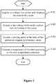
- Figure 1 is a flowchart of a method for monitoring a temperature of a rotor of a permanent magnet synchronous motor according to an embodiment of the present disclosure.
- the method for monitoring the temperature of the rotor according to the embodiment includes steps S101 to S104.
- the a-phase line current of the stator of the permanent magnet synchronous motor is acquired as a first line current
- the b-phase line current of stator is acquired as a second line current
- a temperature of the rotor is calculated according to a rotor temperature expression.
- the first line current, the second line current, the line voltage between the a-phase and the b-phase, the rotating speed of the rotor, an inductance parameter of the permanent magnet synchronous motor and a temperature characteristic equation of a permanent magnet of the rotor are substituted into a preset rotor temperature expression, to calculate a temperature of the rotor.
- the rotor temperature expression is acquired by steps as follows.
- Equation (3-3) is transformed into equations (5-7) and (5-8).
- a calculation formula (5-11) for the extended back electromotive force can be acquired according to equation (5-9).
- e ⁇ e ⁇ pL d + R i ⁇ ⁇ v ⁇ + L d ⁇ L q ⁇ e i ⁇ pL d + R i ⁇ ⁇ v ⁇ + L d ⁇ L q ⁇ e i ⁇
- i ⁇ and i ⁇ can be acquired by measuring i a and i b and transforming i a and i b according to equation (3-1), v ⁇ and v ⁇ are known values outputted from motor vector control, ⁇ e is a measured rotating speed of motor, and L d and L q are known inductance parameters of the motor.
- i d and iq can be acquired by measuring i a and i b and transforming i a and i b according to equation (3-2), ⁇ e is a measured rotating speed of motor, and L d and L q are known inductance parameters of the motor.
- the rotor temperature expression of the permanent magnet of the rotor can be acquired by substituting equation (5-12) into equation (5-6).
- T ⁇ f ⁇ f ⁇ ⁇ f 0 k
- T ⁇ e ⁇ 2 + e ⁇ 2 ⁇ L d ⁇ L q ⁇ e i d ⁇ i ⁇ q ⁇ ⁇ f 0 k T ⁇ ⁇ e
- i a and i b are the first line current and the second line current, respectively.
- a method and a system for monitoring a temperature of a rotor of a permanent magnet synchronous motor are provided according to the present disclosure.
- the a-phase line current and the b-phase line current of the stator of the permanent magnet synchronous motor are acquired as the first line current and the second line current, respectively, and the line voltage between the a-phase and the b-phase of the stator is acquired.
- the first line current, the second line current, the line voltage, the inductance parameter of the permanent magnet synchronous motor and the temperature characteristic equation of the permanent magnet of the rotor are substituted into the preset temperature expression for the permanent magnet of the rotor, to calculate the temperature of the rotor.
- No temperature sensor is pre-embedded into the rotor to monitor the temperature of the permanent magnet of the rotor in the method, thereby avoiding the problem of low system reliability due to the configuration of the temperature sensor to monitor the temperature of the rotor.
- the temperature of the stator core is not measured in the method and system for monitoring the temperature of the rotor, that is, there is no time delay of thermal conduction between the stator core and the rotor, the temperature of the rotor can be acquired timely. Furthermore, a magnetic linkage parameter of the permanent magnet can be derived based on the temperature of the rotor, thereby achieving timely protection for the permanent magnet and compensation for the magnetic linkage parameter.
- the temperature characteristic equation in the embodiment can be acquired by steps as follows.
- E 0 , U a and U ab are respectively an amplitude value of the no-load back electromotive force, a peak value of an a-phase voltage and a peak value of a line voltage of the permanent magnet motor.
- magnetic linkage of a permanent magnet of a rotor corresponding to a certain temperature can be estimated by measuring a line voltage of the motor at a rated rotating speed at the temperature.
- ⁇ f U ab 3 ⁇ e
- an ambient temperature is recorded under a condition that the permanent magnet synchronous motor is in a cold state.
- an ambient temperature of an current environment of the permanent magnet synchronous motor is measured and recorded. Since the permanent magnet synchronous motor is an isothermal body in this case, the ambient temperature is a temperature of the permanent magnet of the rotor.
- a line voltage of the permanent magnet synchronous motor is measured as a first line voltage.
- Temperature rise examination of full power at the rated rotating speed is performed on the permanent magnet motor as a motor, a temperature T h is recorded by a temperature sensor pre-embedded in the stator of the motor after the temperature of the motor is stable.
- the permanent magnet synchronous motor is run to rated power, a temperature of the stator of the permanent magnet synchronous motor is measured after the temperature of the permanent magnet synchronous motor is stable.
- the entire motor is an isothermal body, and the temperature of the stator is regarded as a second rotor temperature.
- the permanent magnet synchronous motor is made unloaded and the permanent magnet synchronous motor is kept running at a rated rotating speed, and a line voltage of the permanent magnet synchronous motor is measured as a second line voltage, and a temperature coefficient of the permanent magnet in the permanent magnet motor is derived.
- Equations (5-3) and (5-4) are expressions for calculating magnetic linkage of the permanent magnet at a certain temperature based on measurement values.
- Magnetic linkage ⁇ f T 0 of the permanent magnet of the motor at 0 degree centigrade can be calculated according to equation (5-4), as shown in equation (5-5), and equation (5-4) is further simplified into equation (5-6).
- Equation (5-6) is the finally obtained temperature characteristic equation of the magnetic linkage of the permanent magnet in the rotor of the permanent magnet motor. It is apparent that a temperature of the permanent magnet can be derived inversely from the magnitude of the magnetic linkage of the permanent magnet in the rotor of the permanent magnet motor at a certain time instant according to equation (5-6).
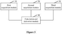
- Figure 3 is a structural diagram of a system for monitoring a temperature of a rotor of a permanent magnet synchronous motor according to another embodiment of the present disclosure.
- the permanent magnet synchronous motor includes a first acquisition module 10, a second acquisition module 20, a third acquisition module 30 and a calculation and derivation module 40.
- the first acquisition module 10 is configured to acquire an a-phase line current and a b-phase line current of a stator.
- the a-phase line current of the stator of the permanent magnet synchronous motor is acquired as a first line current
- the b-phase line current of the stator of the permanent magnet synchronous motor is acquired as a second line current.
- the second acquisition module 20 is configured to acquire a line voltage between the a-phase and the b-phase of the stator.
- the third acquisition module 30 is configured to acquire a rotating speed of the rotor of the permanent magnet synchronous motor.
- the calculation and derivation module 40 is configured to calculate a temperature of the rotor according to a rotor temperature expression.
- the first line current, the second line current, the line voltage between the a-phase and the b-phase and the rotating speed of the rotor which are acquired in above steps, and an inductance parameter of the permanent magnet synchronous motor and a temperature characteristic equation of the permanent magnet of the rotor are substituted into a preset rotor temperature expression, to calculate the temperature of the rotor.
- a system for monitoring a temperature of a rotor of a permanent magnet synchronous motor is provided according to the present disclosure.
- the a-phase line current and the b-phase line current of the stator of the permanent magnet synchronous motor are acquired as the first line current and the second line current, respectively, the line voltage between the a-phase and the b-phase of the stator is acquired.
- the first line current, the second line current, the line voltage and the inductance parameter of the permanent magnet synchronous motor and the temperature characteristic equation of the permanent magnet of the rotor are substituted into the preset temperature expression for the permanent magnet of the rotor, to calculate the temperature of the rotor.
- No temperature sensor is pre-embedded into the rotor to monitor the temperature of the permanent magnet of the rotor in the system, thereby avoiding the problem of low system reliability due to the configuration of the temperature sensor to monitor the temperature of the rotor.
- the temperature of the stator core is not measured in the method for monitoring the temperature of the rotor, that is, there is no time delay of thermal conduction between the stator core and the rotor, the temperature of the rotor can be acquired timely. Furthermore, a magnetic linkage parameter of the permanent magnet can be derived based on the temperature of the rotor, thereby achieving timely protection for the permanent magnet and compensation for the magnetic linkage parameter.
- the calculation and derivation module includes: a first detection unit configured to measure and record a current ambient temperature as a first rotor temperature under a condition that the permanent magnet synchronous motor is in a complete cold state; and a second detection unit configured to drag the permanent magnet synchronous motor to a rated rotating speed in an open-circuit state, and measure a line voltage of the permanent magnet synchronous motor as a first line voltage.
- the first detection unit is further configured to run the permanent magnet synchronous motor to rated power, and measure a temperature of the stator of the permanent magnet synchronous motor as a second rotor temperature after the temperature of the permanent magnet synchronous motor is stable.
- the second detection unit is further configured to, after the permanent magnet synchronous motor runs at the rated power, make the permanent magnet synchronous motor unloaded and keep the permanent magnet synchronous motor running at a rated rotating speed, and measure a line voltage of the permanent magnet synchronous motor as a second line voltage.
- the calculation and derivation module includes a logic operation unit configured to calculate the rotor temperature expression based on the first rotator temperature, the first line voltage, the second rotator temperature, the second line voltage and the rated rotating speed.
- the logic operation unit includes: a first calculation subunit configured to calculate a magnetic linkage expression of the permanent magnet of the permanent magnet synchronous motor based on the first rotor temperature, the first line voltage, the second rotor temperature, the second line voltage and the rated rotating speed; a second calculation subunit configured to calculate magnetic linkage of the permanent magnet at zero degree centigrade according to the magnetic linkage expression; and a third calculation subunit configured to calculate the rotor temperature expression based on the magnetic linkage expression and the magnetic linkage of the permanent magnet.
- the third calculation subunit includes: a first transformation circuit configured to transform a line voltage expression into a stationary two-phase voltage expression in a stationary two-phase ⁇ - ⁇ coordinate system; a definition circuit configured to define an extended back electromotive force expression; a second transformation circuit configured to substitute the extended back electromotive force expression into the stationary two-phase voltage expression, and acquire a magnetic linkage expression of the permanent magnet of the rotor by transformation; and a third transformation circuit configured to substitute the magnetic linkage of the permanent magnet into the magnetic linkage expression of the permanent magnet to acquire the rotor temperature expression.
- system further includes a temperature sensor disposed in a stator core of the permanent magnet synchronous motor and configured to measure the second rotor temperature after the permanent magnet synchronous motor runs at the rated power and the temperature of the permanent magnet synchronous motor is stable.
Landscapes
- Engineering & Computer Science (AREA)
- Power Engineering (AREA)
- Physics & Mathematics (AREA)
- General Physics & Mathematics (AREA)
- Control Of Ac Motors In General (AREA)
Applications Claiming Priority (2)
| Application Number | Priority Date | Filing Date | Title |
|---|---|---|---|
| CN201410452142.1A CN104158463B (zh) | 2014-09-05 | 2014-09-05 | 一种永磁同步电机的转子温度监测方法及系统 |
| PCT/CN2015/088807 WO2016034114A1 (fr) | 2014-09-05 | 2015-09-02 | Procédé et système de surveillance de température de rotor pour moteur synchrone à aimant permanent |
Publications (3)
| Publication Number | Publication Date |
|---|---|
| EP3190697A1 true EP3190697A1 (fr) | 2017-07-12 |
| EP3190697A4 EP3190697A4 (fr) | 2018-02-14 |
| EP3190697B1 EP3190697B1 (fr) | 2020-05-20 |
Family
ID=51883896
Family Applications (1)
| Application Number | Title | Priority Date | Filing Date |
|---|---|---|---|
| EP15838205.1A Active EP3190697B1 (fr) | 2014-09-05 | 2015-09-02 | Procédé et système de surveillance de température de rotor pour moteur synchrone à aimant permanent |
Country Status (5)
| Country | Link |
|---|---|
| US (1) | US10374545B2 (fr) |
| EP (1) | EP3190697B1 (fr) |
| CN (1) | CN104158463B (fr) |
| GB (1) | GB2544703A (fr) |
| WO (1) | WO2016034114A1 (fr) |
Cited By (2)
| Publication number | Priority date | Publication date | Assignee | Title |
|---|---|---|---|---|
| CN113394920A (zh) * | 2021-06-24 | 2021-09-14 | 上海卓荃电子科技有限公司 | 一种电机转子测温系统、智能控温式电机 |
| EP4009501A1 (fr) | 2020-12-02 | 2022-06-08 | pro-micron GmbH | Surveillance d'état d'un élément rotatif, notamment d'un rotor d'un moteur électrique |
Families Citing this family (34)
| Publication number | Priority date | Publication date | Assignee | Title |
|---|---|---|---|---|
| CN104158463B (zh) * | 2014-09-05 | 2016-03-30 | 南车株洲电力机车研究所有限公司 | 一种永磁同步电机的转子温度监测方法及系统 |
| CN105844030B (zh) * | 2016-03-29 | 2018-12-11 | 中国第一汽车股份有限公司 | 一种永磁同步电机转子温度在线估算方法 |
| CN107968619B (zh) * | 2016-10-20 | 2020-06-09 | 上海汽车集团股份有限公司 | 一种电机定子的过温保护方法及装置 |
| CN107487184B (zh) * | 2016-12-09 | 2020-09-18 | 宝沃汽车(中国)有限公司 | 车辆故障保护方法和装置 |
| CN107294451A (zh) * | 2017-07-26 | 2017-10-24 | 中国第汽车股份有限公司 | 永磁同步电机输出转矩在线计算方法 |
| FR3073344B1 (fr) * | 2017-11-09 | 2021-04-30 | Valeo Equip Electr Moteur | Procede de regulation d'un courant electrique delivre par une machine electrique tournante |
| CN107966659A (zh) * | 2017-12-07 | 2018-04-27 | 重庆车辆检测研究院有限公司 | 永磁同步电机中定子绕组温升在线检测方法及检测系统 |
| CN108390617B (zh) * | 2017-12-11 | 2020-01-03 | 深圳腾势新能源汽车有限公司 | 电机转子温度监测方法、装置、存储介质和计算机设备 |
| US10461678B2 (en) * | 2018-03-19 | 2019-10-29 | GM Global Technology Operations LLC | Methods and systems for determining when to apply an adaptative thermal compensation in an operating region of a motor |
| GB2574416A (en) * | 2018-06-05 | 2019-12-11 | Bombardier Transp Gmbh | A method and an apparatus for determining a temperature of a rotor |
| CN109039219A (zh) * | 2018-07-06 | 2018-12-18 | 浙江零跑科技有限公司 | 一种基于转子磁钢温度的车用电机保护方法 |
| CN111211719B (zh) * | 2018-11-06 | 2021-09-24 | 株洲中车时代电气股份有限公司 | 一种永磁同步电机转子磁钢温度估算方法及系统 |
| CN109586651B (zh) * | 2018-11-20 | 2021-02-26 | 上海电机系统节能工程技术研究中心有限公司 | 一种永磁同步电机转子永磁体温度的在线监测方法 |
| CN109713973B (zh) * | 2019-03-27 | 2019-06-18 | 南京埃斯顿自动化股份有限公司 | 永磁同步电机定子磁链矩阵提取方法及其应用 |
| CN110912482B (zh) * | 2019-12-11 | 2023-08-18 | 长沙市日业电气有限公司 | 一种永磁同步电机磁链及温度估计方法 |
| CN113726241B (zh) * | 2020-05-26 | 2024-05-31 | 苏州汇川联合动力系统股份有限公司 | 电机转矩的温升补偿的方法、设备和计算机可读存储介质 |
| CN112032033A (zh) * | 2020-09-25 | 2020-12-04 | 江苏佳星泵阀设备有限公司 | 一种永磁泵液晶触屏显示控制系统 |
| CN112213638B (zh) * | 2020-10-28 | 2021-12-14 | 瑞声新能源发展(常州)有限公司科教城分公司 | 一种电机线圈的发热状态监测方法、相关设备和介质 |
| CN114189186B (zh) * | 2020-11-20 | 2024-07-23 | 蜂巢传动系统(江苏)有限公司保定研发分公司 | 永磁同步电机的永磁体温度估算方法及装置 |
| CN112564580B (zh) * | 2020-12-03 | 2022-08-19 | 湖南大学 | 考虑磁饱和的表贴式永磁同步电机的永磁体温度估算方法 |
| EP4016836B1 (fr) | 2020-12-18 | 2023-10-11 | Volvo Truck Corporation | Procédé de catégorisation des performances d'une machine à traction électrique qui est un moteur synchrone à aimant permanent |
| EP4016833B1 (fr) | 2020-12-18 | 2025-01-22 | Volvo Truck Corporation | Procede permettant d'adapter les parametres de controle d'une machine a traction electrique etant un moteur synchrone a aimant permanent |
| CN113985280B (zh) * | 2021-11-01 | 2024-11-26 | 上海汽车变速器有限公司 | 永磁同步电机测试方法、装置、设备及存储介质 |
| CN115833684B (zh) * | 2021-12-15 | 2023-10-20 | 宁德时代新能源科技股份有限公司 | 永磁同步电机的转子温度的估算方法、装置和计算机设备 |
| CN114094914B (zh) * | 2022-01-17 | 2022-04-19 | 南京双南威动科技有限公司 | 一种表贴式永磁同步电机转子永磁体温度在线测量方法 |
| CN114679114B (zh) * | 2022-03-29 | 2024-10-18 | 南京航空航天大学 | 一种高速永磁电机转子温度的实时监测方法 |
| CN114928289A (zh) * | 2022-05-23 | 2022-08-19 | 东风汽车集团股份有限公司 | 一种永磁同步电机转子温度估算方法 |
| CN114928290A (zh) * | 2022-05-23 | 2022-08-19 | 东风汽车集团股份有限公司 | 一种永磁同步电机转子温度简化估计方法 |
| CN116191985A (zh) * | 2023-03-20 | 2023-05-30 | 一汽解放汽车有限公司 | 永磁同步电机的转子温度确定方法、装置和计算机设备 |
| CN116317830A (zh) * | 2023-03-27 | 2023-06-23 | 臻驱科技(上海)有限公司 | 一种电机转子温度计算方法、装置、车辆及介质 |
| CN116614035B (zh) * | 2023-05-29 | 2024-06-28 | 重庆青山工业有限责任公司 | 一种永磁同步电机转子温度实时在线估算方法 |
| CN117294198B (zh) * | 2023-11-24 | 2024-02-20 | 珠海格力电器股份有限公司 | 一种电机磁链补偿方法、装置、存储介质及控制器 |
| WO2025170948A1 (fr) * | 2024-02-05 | 2025-08-14 | Siemens Healthcare Diagnostics Inc. | Compensation thermique de bobines de commutation dans des moteurs à courant continu sans balai |
| CN118487531B (zh) * | 2024-07-15 | 2024-10-22 | 潍柴动力股份有限公司 | 一种电机永磁体温度确定方法及相关装置、存储介质 |
Family Cites Families (12)
| Publication number | Priority date | Publication date | Assignee | Title |
|---|---|---|---|---|
| JP4501433B2 (ja) | 2003-10-24 | 2010-07-14 | ダイキン工業株式会社 | Dcモータのコイル温度推定方法およびその装置 |
| DE102008040725A1 (de) * | 2008-07-25 | 2010-01-28 | Robert Bosch Gmbh | Verfahren und Vorrichtung zur Ermittlung der Rotortemperatur einer permanenterregten Synchronmaschine |
| CN101769797A (zh) * | 2009-01-06 | 2010-07-07 | 李虎 | 一种用于预测永磁同步电动机中永磁体温度的温升分析方法 |
| US8421255B2 (en) | 2009-10-28 | 2013-04-16 | General Electric Company | System and method for determining the temperature of a permanent magnet in a machine |
| US7979171B2 (en) * | 2010-09-21 | 2011-07-12 | Ford Global Technologies, Llc | Permanent magnet temperature estimation |
| CN102710208B (zh) * | 2012-06-01 | 2015-01-14 | 万高(杭州)科技有限公司 | 基于温度变化的永磁同步电机自适应控制方法 |
| JP2014057385A (ja) * | 2012-09-11 | 2014-03-27 | Toyota Motor Corp | 回転電機の制御装置及びその制御装置を備えた回転電機駆動システム |
| CN104718694B (zh) * | 2012-10-12 | 2017-05-10 | 三菱电机株式会社 | 同步电机控制装置 |
| CN103888041A (zh) * | 2012-12-21 | 2014-06-25 | 上海大郡动力控制技术有限公司 | 永磁电机永磁体温度的在线估算方法 |
| FR3006125B1 (fr) * | 2013-05-21 | 2015-05-15 | Ifp Energies Now | Procede et systeme de determination de temperatures internes d'une machine electrique synchrone au moyens d'observateurs d'etat |
| CN104158463B (zh) * | 2014-09-05 | 2016-03-30 | 南车株洲电力机车研究所有限公司 | 一种永磁同步电机的转子温度监测方法及系统 |
| US9372235B2 (en) * | 2014-09-30 | 2016-06-21 | Deere & Company | Methods of estimating rotor magnet temperature and systems thereof |
-
2014
- 2014-09-05 CN CN201410452142.1A patent/CN104158463B/zh active Active
-
2015
- 2015-09-02 EP EP15838205.1A patent/EP3190697B1/fr active Active
- 2015-09-02 WO PCT/CN2015/088807 patent/WO2016034114A1/fr not_active Ceased
- 2015-09-02 US US15/507,459 patent/US10374545B2/en active Active
- 2015-09-02 GB GB1704306.8A patent/GB2544703A/en not_active Withdrawn
Cited By (4)
| Publication number | Priority date | Publication date | Assignee | Title |
|---|---|---|---|---|
| EP4009501A1 (fr) | 2020-12-02 | 2022-06-08 | pro-micron GmbH | Surveillance d'état d'un élément rotatif, notamment d'un rotor d'un moteur électrique |
| WO2022117265A1 (fr) | 2020-12-02 | 2022-06-09 | Pro-Micron Gmbh | Surveillance d'état pour un élément rotatif d'un moteur ou d'une machine de travail, plus particulièrement pour le rotor d'un moteur électrique |
| US12399068B2 (en) | 2020-12-02 | 2025-08-26 | Pro-Micron Gmbh | Status monitoring for a rotating element of a motor or work machine, more particularly for the rotor of an electric motor |
| CN113394920A (zh) * | 2021-06-24 | 2021-09-14 | 上海卓荃电子科技有限公司 | 一种电机转子测温系统、智能控温式电机 |
Also Published As
| Publication number | Publication date |
|---|---|
| GB2544703A8 (en) | 2017-06-21 |
| US10374545B2 (en) | 2019-08-06 |
| GB201704306D0 (en) | 2017-05-03 |
| WO2016034114A1 (fr) | 2016-03-10 |
| EP3190697A4 (fr) | 2018-02-14 |
| US20170338765A1 (en) | 2017-11-23 |
| CN104158463A (zh) | 2014-11-19 |
| GB2544703A (en) | 2017-05-24 |
| CN104158463B (zh) | 2016-03-30 |
| EP3190697B1 (fr) | 2020-05-20 |
Similar Documents
| Publication | Publication Date | Title |
|---|---|---|
| EP3190697A1 (fr) | Procédé et système de surveillance de température de rotor pour moteur synchrone à aimant permanent | |
| US9523739B2 (en) | Method and apparatus for measuring rotor resistance of induction motor | |
| CN104283479B (zh) | 基于三维电机参数表的永磁同步电机负载转矩监测系统 | |
| CN111211719B (zh) | 一种永磁同步电机转子磁钢温度估算方法及系统 | |
| CN103187919B (zh) | 一种永磁同步电机弱磁调速的系统和方法 | |
| CN104360171B (zh) | 永磁同步电机电感参数测量方法 | |
| CN103248307B (zh) | 感应电机调速系统的电流传感器故障诊断方法 | |
| CN109713973B (zh) | 永磁同步电机定子磁链矩阵提取方法及其应用 | |
| Wang et al. | Induction motor broken rotor bar fault diagnosis based on third-order energy operator demodulated current signal | |
| CN101650390B (zh) | 表面式交流永磁同步电机的定子电感参数在线测量方法 | |
| CN103346726B (zh) | 基于扩展磁链观测器的永磁同步电机定子磁链观测方法 | |
| US20160274167A1 (en) | Buss current-based short circuit fault diagnosing method for power converter of switched reluctance motor | |
| US9647602B1 (en) | Determination of stator winding resistance in an electric machine | |
| CN110726962B (zh) | 一种永磁直线电机电流传感器增益故障诊断方法 | |
| CN103245878B (zh) | 一种输电线路单相接地故障单端测距方法 | |
| CN106505924A (zh) | 电机定子电阻的在线辨识方法、装置和电机控制系统 | |
| CN106788056B (zh) | 电机定子电阻的在线辨识方法、装置和电机控制系统 | |
| US9755567B2 (en) | Determination of permanent magnetic flux in an electric machine | |
| CN112083349A (zh) | 一种永磁同步电机定子绕组匝间短路故障诊断方法 | |
| CN103245876B (zh) | 利用电压降实部特性实现线路相间故障单端测距方法 | |
| CN104201961A (zh) | 一种测量三相永磁同步电动机初始静态参数的方案 | |
| Meng et al. | A non-invasive dual-EKF-based rotor temperature estimation technique for permanent magnet machines | |
| EP3576290B1 (fr) | Détermination d'angle pour générateur | |
| KR20150005044A (ko) | 모터 회전자 온도 추정 장치 및 방법 | |
| Zhang et al. | Rotor Thermal Monitoring Scheme for Direct-Torque-Controlled Interior Permanent Magnet Synchronous Machines via High-Frequency Rotating Flux or Torque Injection |
Legal Events
| Date | Code | Title | Description |
|---|---|---|---|
| STAA | Information on the status of an ep patent application or granted ep patent |
Free format text: STATUS: THE INTERNATIONAL PUBLICATION HAS BEEN MADE |
|
| PUAI | Public reference made under article 153(3) epc to a published international application that has entered the european phase |
Free format text: ORIGINAL CODE: 0009012 |
|
| STAA | Information on the status of an ep patent application or granted ep patent |
Free format text: STATUS: REQUEST FOR EXAMINATION WAS MADE |
|
| 17P | Request for examination filed |
Effective date: 20170317 |
|
| AK | Designated contracting states |
Kind code of ref document: A1 Designated state(s): AL AT BE BG CH CY CZ DE DK EE ES FI FR GB GR HR HU IE IS IT LI LT LU LV MC MK MT NL NO PL PT RO RS SE SI SK SM TR |
|
| AX | Request for extension of the european patent |
Extension state: BA ME |
|
| DAV | Request for validation of the european patent (deleted) | ||
| DAX | Request for extension of the european patent (deleted) | ||
| A4 | Supplementary search report drawn up and despatched |
Effective date: 20180117 |
|
| RIC1 | Information provided on ipc code assigned before grant |
Ipc: G01K 13/08 20060101AFI20180111BHEP Ipc: H02K 21/00 20060101ALI20180111BHEP Ipc: G01R 31/34 20060101ALI20180111BHEP Ipc: H02P 29/66 20160101ALI20180111BHEP Ipc: H02P 29/60 20160101ALI20180111BHEP |
|
| REG | Reference to a national code |
Ref country code: DE Ref legal event code: R079 Ref document number: 602015053139 Country of ref document: DE Free format text: PREVIOUS MAIN CLASS: H02P0021140000 Ipc: G01K0013080000 |
|
| GRAP | Despatch of communication of intention to grant a patent |
Free format text: ORIGINAL CODE: EPIDOSNIGR1 |
|
| STAA | Information on the status of an ep patent application or granted ep patent |
Free format text: STATUS: GRANT OF PATENT IS INTENDED |
|
| RIC1 | Information provided on ipc code assigned before grant |
Ipc: H02K 21/00 20060101ALI20191111BHEP Ipc: G01K 13/08 20060101AFI20191111BHEP Ipc: H02P 29/60 20160101ALI20191111BHEP Ipc: H02P 29/66 20160101ALI20191111BHEP Ipc: G01K 7/42 20060101ALI20191111BHEP Ipc: G01R 31/34 20060101ALI20191111BHEP |
|
| INTG | Intention to grant announced |
Effective date: 20191210 |
|
| GRAS | Grant fee paid |
Free format text: ORIGINAL CODE: EPIDOSNIGR3 |
|
| GRAA | (expected) grant |
Free format text: ORIGINAL CODE: 0009210 |
|
| STAA | Information on the status of an ep patent application or granted ep patent |
Free format text: STATUS: THE PATENT HAS BEEN GRANTED |
|
| AK | Designated contracting states |
Kind code of ref document: B1 Designated state(s): AL AT BE BG CH CY CZ DE DK EE ES FI FR GB GR HR HU IE IS IT LI LT LU LV MC MK MT NL NO PL PT RO RS SE SI SK SM TR |
|
| REG | Reference to a national code |
Ref country code: GB Ref legal event code: FG4D |
|
| REG | Reference to a national code |
Ref country code: CH Ref legal event code: EP |
|
| REG | Reference to a national code |
Ref country code: DE Ref legal event code: R096 Ref document number: 602015053139 Country of ref document: DE |
|
| REG | Reference to a national code |
Ref country code: AT Ref legal event code: REF Ref document number: 1272901 Country of ref document: AT Kind code of ref document: T Effective date: 20200615 |
|
| REG | Reference to a national code |
Ref country code: LT Ref legal event code: MG4D |
|
| REG | Reference to a national code |
Ref country code: NL Ref legal event code: MP Effective date: 20200520 |
|
| PG25 | Lapsed in a contracting state [announced via postgrant information from national office to epo] |
Ref country code: LT Free format text: LAPSE BECAUSE OF FAILURE TO SUBMIT A TRANSLATION OF THE DESCRIPTION OR TO PAY THE FEE WITHIN THE PRESCRIBED TIME-LIMIT Effective date: 20200520 Ref country code: FI Free format text: LAPSE BECAUSE OF FAILURE TO SUBMIT A TRANSLATION OF THE DESCRIPTION OR TO PAY THE FEE WITHIN THE PRESCRIBED TIME-LIMIT Effective date: 20200520 Ref country code: GR Free format text: LAPSE BECAUSE OF FAILURE TO SUBMIT A TRANSLATION OF THE DESCRIPTION OR TO PAY THE FEE WITHIN THE PRESCRIBED TIME-LIMIT Effective date: 20200821 Ref country code: SE Free format text: LAPSE BECAUSE OF FAILURE TO SUBMIT A TRANSLATION OF THE DESCRIPTION OR TO PAY THE FEE WITHIN THE PRESCRIBED TIME-LIMIT Effective date: 20200520 Ref country code: NO Free format text: LAPSE BECAUSE OF FAILURE TO SUBMIT A TRANSLATION OF THE DESCRIPTION OR TO PAY THE FEE WITHIN THE PRESCRIBED TIME-LIMIT Effective date: 20200820 Ref country code: IS Free format text: LAPSE BECAUSE OF FAILURE TO SUBMIT A TRANSLATION OF THE DESCRIPTION OR TO PAY THE FEE WITHIN THE PRESCRIBED TIME-LIMIT Effective date: 20200920 Ref country code: PT Free format text: LAPSE BECAUSE OF FAILURE TO SUBMIT A TRANSLATION OF THE DESCRIPTION OR TO PAY THE FEE WITHIN THE PRESCRIBED TIME-LIMIT Effective date: 20200921 |
|
| PG25 | Lapsed in a contracting state [announced via postgrant information from national office to epo] |
Ref country code: RS Free format text: LAPSE BECAUSE OF FAILURE TO SUBMIT A TRANSLATION OF THE DESCRIPTION OR TO PAY THE FEE WITHIN THE PRESCRIBED TIME-LIMIT Effective date: 20200520 Ref country code: HR Free format text: LAPSE BECAUSE OF FAILURE TO SUBMIT A TRANSLATION OF THE DESCRIPTION OR TO PAY THE FEE WITHIN THE PRESCRIBED TIME-LIMIT Effective date: 20200520 Ref country code: LV Free format text: LAPSE BECAUSE OF FAILURE TO SUBMIT A TRANSLATION OF THE DESCRIPTION OR TO PAY THE FEE WITHIN THE PRESCRIBED TIME-LIMIT Effective date: 20200520 Ref country code: BG Free format text: LAPSE BECAUSE OF FAILURE TO SUBMIT A TRANSLATION OF THE DESCRIPTION OR TO PAY THE FEE WITHIN THE PRESCRIBED TIME-LIMIT Effective date: 20200820 |
|
| REG | Reference to a national code |
Ref country code: AT Ref legal event code: MK05 Ref document number: 1272901 Country of ref document: AT Kind code of ref document: T Effective date: 20200520 |
|
| PG25 | Lapsed in a contracting state [announced via postgrant information from national office to epo] |
Ref country code: NL Free format text: LAPSE BECAUSE OF FAILURE TO SUBMIT A TRANSLATION OF THE DESCRIPTION OR TO PAY THE FEE WITHIN THE PRESCRIBED TIME-LIMIT Effective date: 20200520 Ref country code: AL Free format text: LAPSE BECAUSE OF FAILURE TO SUBMIT A TRANSLATION OF THE DESCRIPTION OR TO PAY THE FEE WITHIN THE PRESCRIBED TIME-LIMIT Effective date: 20200520 |
|
| PG25 | Lapsed in a contracting state [announced via postgrant information from national office to epo] |
Ref country code: IT Free format text: LAPSE BECAUSE OF FAILURE TO SUBMIT A TRANSLATION OF THE DESCRIPTION OR TO PAY THE FEE WITHIN THE PRESCRIBED TIME-LIMIT Effective date: 20200520 Ref country code: EE Free format text: LAPSE BECAUSE OF FAILURE TO SUBMIT A TRANSLATION OF THE DESCRIPTION OR TO PAY THE FEE WITHIN THE PRESCRIBED TIME-LIMIT Effective date: 20200520 Ref country code: DK Free format text: LAPSE BECAUSE OF FAILURE TO SUBMIT A TRANSLATION OF THE DESCRIPTION OR TO PAY THE FEE WITHIN THE PRESCRIBED TIME-LIMIT Effective date: 20200520 Ref country code: AT Free format text: LAPSE BECAUSE OF FAILURE TO SUBMIT A TRANSLATION OF THE DESCRIPTION OR TO PAY THE FEE WITHIN THE PRESCRIBED TIME-LIMIT Effective date: 20200520 Ref country code: SM Free format text: LAPSE BECAUSE OF FAILURE TO SUBMIT A TRANSLATION OF THE DESCRIPTION OR TO PAY THE FEE WITHIN THE PRESCRIBED TIME-LIMIT Effective date: 20200520 Ref country code: ES Free format text: LAPSE BECAUSE OF FAILURE TO SUBMIT A TRANSLATION OF THE DESCRIPTION OR TO PAY THE FEE WITHIN THE PRESCRIBED TIME-LIMIT Effective date: 20200520 Ref country code: CZ Free format text: LAPSE BECAUSE OF FAILURE TO SUBMIT A TRANSLATION OF THE DESCRIPTION OR TO PAY THE FEE WITHIN THE PRESCRIBED TIME-LIMIT Effective date: 20200520 Ref country code: RO Free format text: LAPSE BECAUSE OF FAILURE TO SUBMIT A TRANSLATION OF THE DESCRIPTION OR TO PAY THE FEE WITHIN THE PRESCRIBED TIME-LIMIT Effective date: 20200520 |
|
| REG | Reference to a national code |
Ref country code: DE Ref legal event code: R097 Ref document number: 602015053139 Country of ref document: DE |
|
| PG25 | Lapsed in a contracting state [announced via postgrant information from national office to epo] |
Ref country code: SK Free format text: LAPSE BECAUSE OF FAILURE TO SUBMIT A TRANSLATION OF THE DESCRIPTION OR TO PAY THE FEE WITHIN THE PRESCRIBED TIME-LIMIT Effective date: 20200520 Ref country code: PL Free format text: LAPSE BECAUSE OF FAILURE TO SUBMIT A TRANSLATION OF THE DESCRIPTION OR TO PAY THE FEE WITHIN THE PRESCRIBED TIME-LIMIT Effective date: 20200520 |
|
| PLBE | No opposition filed within time limit |
Free format text: ORIGINAL CODE: 0009261 |
|
| STAA | Information on the status of an ep patent application or granted ep patent |
Free format text: STATUS: NO OPPOSITION FILED WITHIN TIME LIMIT |
|
| 26N | No opposition filed |
Effective date: 20210223 |
|
| PG25 | Lapsed in a contracting state [announced via postgrant information from national office to epo] |
Ref country code: MC Free format text: LAPSE BECAUSE OF FAILURE TO SUBMIT A TRANSLATION OF THE DESCRIPTION OR TO PAY THE FEE WITHIN THE PRESCRIBED TIME-LIMIT Effective date: 20200520 |
|
| REG | Reference to a national code |
Ref country code: CH Ref legal event code: PL |
|
| PG25 | Lapsed in a contracting state [announced via postgrant information from national office to epo] |
Ref country code: SI Free format text: LAPSE BECAUSE OF FAILURE TO SUBMIT A TRANSLATION OF THE DESCRIPTION OR TO PAY THE FEE WITHIN THE PRESCRIBED TIME-LIMIT Effective date: 20200520 |
|
| REG | Reference to a national code |
Ref country code: BE Ref legal event code: MM Effective date: 20200930 |
|
| PG25 | Lapsed in a contracting state [announced via postgrant information from national office to epo] |
Ref country code: LU Free format text: LAPSE BECAUSE OF NON-PAYMENT OF DUE FEES Effective date: 20200902 |
|
| PG25 | Lapsed in a contracting state [announced via postgrant information from national office to epo] |
Ref country code: FR Free format text: LAPSE BECAUSE OF NON-PAYMENT OF DUE FEES Effective date: 20200930 |
|
| PG25 | Lapsed in a contracting state [announced via postgrant information from national office to epo] |
Ref country code: IE Free format text: LAPSE BECAUSE OF NON-PAYMENT OF DUE FEES Effective date: 20200902 Ref country code: LI Free format text: LAPSE BECAUSE OF NON-PAYMENT OF DUE FEES Effective date: 20200930 Ref country code: BE Free format text: LAPSE BECAUSE OF NON-PAYMENT OF DUE FEES Effective date: 20200930 Ref country code: CH Free format text: LAPSE BECAUSE OF NON-PAYMENT OF DUE FEES Effective date: 20200930 |
|
| PG25 | Lapsed in a contracting state [announced via postgrant information from national office to epo] |
Ref country code: TR Free format text: LAPSE BECAUSE OF FAILURE TO SUBMIT A TRANSLATION OF THE DESCRIPTION OR TO PAY THE FEE WITHIN THE PRESCRIBED TIME-LIMIT Effective date: 20200520 Ref country code: MT Free format text: LAPSE BECAUSE OF FAILURE TO SUBMIT A TRANSLATION OF THE DESCRIPTION OR TO PAY THE FEE WITHIN THE PRESCRIBED TIME-LIMIT Effective date: 20200520 Ref country code: CY Free format text: LAPSE BECAUSE OF FAILURE TO SUBMIT A TRANSLATION OF THE DESCRIPTION OR TO PAY THE FEE WITHIN THE PRESCRIBED TIME-LIMIT Effective date: 20200520 |
|
| PG25 | Lapsed in a contracting state [announced via postgrant information from national office to epo] |
Ref country code: MK Free format text: LAPSE BECAUSE OF FAILURE TO SUBMIT A TRANSLATION OF THE DESCRIPTION OR TO PAY THE FEE WITHIN THE PRESCRIBED TIME-LIMIT Effective date: 20200520 |
|
| PGFP | Annual fee paid to national office [announced via postgrant information from national office to epo] |
Ref country code: DE Payment date: 20250916 Year of fee payment: 11 |
|
| PGFP | Annual fee paid to national office [announced via postgrant information from national office to epo] |
Ref country code: GB Payment date: 20250919 Year of fee payment: 11 |