EP3191678B1 - Raccord mécanique dynamique de tube ascenseur - Google Patents
Raccord mécanique dynamique de tube ascenseur Download PDFInfo
- Publication number
- EP3191678B1 EP3191678B1 EP15840835.1A EP15840835A EP3191678B1 EP 3191678 B1 EP3191678 B1 EP 3191678B1 EP 15840835 A EP15840835 A EP 15840835A EP 3191678 B1 EP3191678 B1 EP 3191678B1
- Authority
- EP
- European Patent Office
- Prior art keywords
- box
- seal
- pin
- connector system
- component
- Prior art date
- Legal status (The legal status is an assumption and is not a legal conclusion. Google has not performed a legal analysis and makes no representation as to the accuracy of the status listed.)
- Active
Links
Images



Classifications
-
- E—FIXED CONSTRUCTIONS
- E21—EARTH OR ROCK DRILLING; MINING
- E21B—EARTH OR ROCK DRILLING; OBTAINING OIL, GAS, WATER, SOLUBLE OR MELTABLE MATERIALS OR A SLURRY OF MINERALS FROM WELLS
- E21B17/00—Drilling rods or pipes; Flexible drill strings; Kellies; Drill collars; Sucker rods; Cables; Casings; Tubings
- E21B17/02—Couplings; joints
- E21B17/08—Casing joints
- E21B17/085—Riser connections
-
- E—FIXED CONSTRUCTIONS
- E21—EARTH OR ROCK DRILLING; MINING
- E21B—EARTH OR ROCK DRILLING; OBTAINING OIL, GAS, WATER, SOLUBLE OR MELTABLE MATERIALS OR A SLURRY OF MINERALS FROM WELLS
- E21B17/00—Drilling rods or pipes; Flexible drill strings; Kellies; Drill collars; Sucker rods; Cables; Casings; Tubings
- E21B17/02—Couplings; joints
- E21B17/04—Couplings; joints between rod or the like and bit or between rod and rod or the like
- E21B17/046—Couplings; joints between rod or the like and bit or between rod and rod or the like with ribs, pins, or jaws, and complementary grooves or the like, e.g. bayonet catches
-
- E—FIXED CONSTRUCTIONS
- E21—EARTH OR ROCK DRILLING; MINING
- E21B—EARTH OR ROCK DRILLING; OBTAINING OIL, GAS, WATER, SOLUBLE OR MELTABLE MATERIALS OR A SLURRY OF MINERALS FROM WELLS
- E21B19/00—Handling rods, casings, tubes or the like outside the borehole, e.g. in the derrick; Apparatus for feeding the rods or cables
- E21B19/002—Handling rods, casings, tubes or the like outside the borehole, e.g. in the derrick; Apparatus for feeding the rods or cables specially adapted for underwater drilling
- E21B19/004—Handling rods, casings, tubes or the like outside the borehole, e.g. in the derrick; Apparatus for feeding the rods or cables specially adapted for underwater drilling supporting a riser from a drilling or production platform
-
- F—MECHANICAL ENGINEERING; LIGHTING; HEATING; WEAPONS; BLASTING
- F16—ENGINEERING ELEMENTS AND UNITS; GENERAL MEASURES FOR PRODUCING AND MAINTAINING EFFECTIVE FUNCTIONING OF MACHINES OR INSTALLATIONS; THERMAL INSULATION IN GENERAL
- F16L—PIPES; JOINTS OR FITTINGS FOR PIPES; SUPPORTS FOR PIPES, CABLES OR PROTECTIVE TUBING; MEANS FOR THERMAL INSULATION IN GENERAL
- F16L15/00—Screw-threaded joints; Forms of screw-threads for such joints
- F16L15/001—Screw-threaded joints; Forms of screw-threads for such joints with conical threads
- F16L15/004—Screw-threaded joints; Forms of screw-threads for such joints with conical threads with axial sealings having at least one plastically deformable sealing surface
-
- E—FIXED CONSTRUCTIONS
- E21—EARTH OR ROCK DRILLING; MINING
- E21B—EARTH OR ROCK DRILLING; OBTAINING OIL, GAS, WATER, SOLUBLE OR MELTABLE MATERIALS OR A SLURRY OF MINERALS FROM WELLS
- E21B17/00—Drilling rods or pipes; Flexible drill strings; Kellies; Drill collars; Sucker rods; Cables; Casings; Tubings
-
- E—FIXED CONSTRUCTIONS
- E21—EARTH OR ROCK DRILLING; MINING
- E21B—EARTH OR ROCK DRILLING; OBTAINING OIL, GAS, WATER, SOLUBLE OR MELTABLE MATERIALS OR A SLURRY OF MINERALS FROM WELLS
- E21B19/00—Handling rods, casings, tubes or the like outside the borehole, e.g. in the derrick; Apparatus for feeding the rods or cables
Definitions
- the present disclosure relates generally to high-strength, fatigue-resistant pipe connectors for pipelines; and, more specifically but not by way of limitation, to high-strength, fatigue-resistant pipe connectors for offshore risers and pipelines, such as, for example, those connected to floating production systems (FPSs) principally used in the offshore production of oil and gas.
- FPSs floating production systems
- Certain concentrically (e.g., non-helical) threaded pin-and-box connector systems are known in the art for connecting large-diameter (e.g., 12 to 36 inch, i.e., 30.48 to 91.44 cm) offshore tendon and riser pipes.
- Such connector systems have proven difficult to adapt to smaller-diameter (e.g., 6 or 8 inch, i.e., 15.24 or 20.32 cm) pipes.
- the pin and box of such connectors systems are typically engaged and disengaged by providing hydraulic fluid under high pressure (typically 5,000 to 10,000 psi, 34473.8 to 68947.6 kPa) in the threaded annulus between the pin and box, thereby expanding the box and contracting the pin in their respective threaded diameters.
- high pressure typically 5,000 to 10,000 psi, 34473.8 to 68947.6 kPa
- the required thread disengagement of such smaller-diameter connector systems may exceed the yield strength of materials (e.g., common steel alloys) that are typically used for such connectors. While higher-strength alloys and materials may be used for such connectors, their use may be impractical. For example, such materials may be incompatible with pipeline fluids, environmental conditions (e.g., seawater), or may be difficult to weld to the common alloys that are typically used for connected pipe.
- GB 2497193A considered the closest prior art, discloses a subsea riser assembly that connects two tubular members with axial movement of an outer sleeve.
- the assembly includes a first tubular member having an end, and a second tubular member having an end with a plurality of box and fingers separated by slots ( fig 4A ), the second tubular member coaxial with the first tubular member.
- the end of the first tubular member is inserted into the end of the second tubular member.
- An outer sleeve having an inner diameter that engages an outer diameter of each box end finger.
- US 2011/0227338 discloses In a pipe joint where two pipe sections have threadably engaged end portions, joint ends are substantially sealed to each other by a sealing surface on one pipe section that substantially abuts a sealing surface on the other pipe section. In one joint, a ring-shaped cutout is formed in a first pipe section and a ring-shaped spacer is located in the cutout.
- the spacer is chosen from several that have slightly different lengths so the spacer end contacts the corresponding sealing surface.
- US 5794985 discloses threaded pipe connection is disclosed for connecting two joints of pipe having externally threaded pin members, one pin member having external right-hand threads and the other pin member having left-hand threads.
- An internally threaded coupling having right and left-hand threads that mates with the threads on the pin members.
- An internal pressure seal ring is positioned to provide a seal between the ends of the pin members.
- a plurality of mating lugs and grooves on the ends of the pin members hold the pins from relative rotation when the connection is being made up.
- a metal-to-metal seal located between each pin member and the coupling adjacent each end of the coupling isolates the threads of the connection from the ambient environment thus sealing off the pipe annulus from external pressure due to hydrostatic head.
- Indicia such as engaging surfaces or aligned scribe lines on the pin members ensure that the sealing surfaces on the coupling and the pin members that form the external seals are positioned to properly engage and form seals when the connection is made up.
- the present apparatuses provide a new and useful high-strength and fatigue-resistant pipe connector for pipelines that is simpler in construction, more universally usable in various applications, and more versatile in operation than previously known connectors.
- the present connectors include a pin component and box component each including mating frusto-conical, concentrically (non-helically) grooved or threaded mating surfaces configured to threadingly interlock the pin and box components, and flat mating surfaces that seal and preload via the axial advancement of the pin into the box.
- axial movement of the pin into the tapered mating box results in the radial expansion of the box and radial contraction of the pin until the concentric thread patterns match and interlockingly snap into the connected position, such that upon snap engagement, the connector is sealed and preloaded at the abutment shoulders of the outer diameter (OD) and inner diameter (ID) of the pin and box.
- contoured radial protrusions in the OD and/or ID of the box component, and/or in the OD of the pin component are included to strengthen and control radial compliance of the respective components so that the connector walls are not overstressed by hydraulic pressurized-displacement employed during connection or disconnection.
- a wedge-shaped, resilient ring e.g., elastically deformable under pressures and forces applied during connection or disconnection of the box and pin components
- Some embodiments of the present connector systems comprise: a pin component defining a hollow interior region with a substantially constant first inner diameter (ID) between a proximal end of the pin component and a seal portion adjacent a distal end of the pin component, and having a tapered exterior surface with a plurality of teeth, the seal portion having a second ID that is larger than the first ID of the pin component; and a box component having a tapered interior surface with a plurality of teeth configured to engage the teeth of the pin component, and having an exterior surface that has a first portion having a substantially constant first outer diameter (OD) extending along a majority of the length of the box component, and a second contoured portion having a variable OD that varies between the first portion and a distal end of the box component.
- ID first inner diameter
- OD substantially constant first outer diameter
- Some embodiments of the present connector systems further comprise: a seal ring having an OD and configured to be disposed in the ID seal portion of the pin component such that an OD of the seal ring abuts the second ID of the pin component.
- the seal ring includes an inner surface with a first width, an outer surface with a second width that is smaller than the inner surface, and two angled lateral surfaces extending between the inner surface and outer surface.
- the lateral surfaces are at mirrored angles of equal magnitude relative to an axis that bisects each of the upper and lower surfaces.
- the seal ring includes an inner surface with a first width, an outer surface that is parallel to the inner surface, and two lateral surfaces that are each perpendicular to the inner surface and outer surface.
- a fillet joins the outer surface and one of the lateral surfaces.
- the seal portion of the pin component includes an annular, longitudinal protrusion with a radially inner surface defining the second ID.
- a proximal end of the box component includes an annular, longitudinal ID seal groove configured to receive the protrusion of the ID seal portion.
- the ID seal groove is configured to receive the protrusion of the ID seal portion with an interference fit.
- the distal end of box component includes an OD seal portion having a second OD that is smaller than the first OD of the box to define an annular, longitudinal protrusion.
- a proximal end of the pin component includes an annular, longitudinal OD seal groove configured to receive the protrusion of the OD seal portion.
- the OD seal groove is configured to receive the longitudinal protrusion of the OD seal portion with an interference fit.
- the variable OD of the second portion of the box component first increases with distance away from the first OD of the first portion of the box component to a maximum variable OD, and then decreases with further distance from the first OD of the first portion to a minimum variable OD.
- the minimum variable OD is substantially equal to the first OD of the first portion of the box component.
- a sidewall of the box component along the portion in which the variable OD decreases has a substantially constant thickness between the maximum variable OD and the ID seal portion.
- the sidewall of the box component has a substantially constant thickness between the first OD and the ID seal portion
- the plurality of teeth of each of the pin component and the box component comprise concentric, non-helical threads.
- the teeth of the pin component are configured to engage the teeth of the box component to attaches the pin component to the box component.
- the teeth of the pin and box components are configured to be disengaged by pressurization between the external surface of the pin component and the internal surface of the box component.
- Some embodiments further comprise: a pressurization component configured to pressurize an interface between the exterior surface of the pin component and the interior surface of the box component.
- the foregoing embodiments provide a high-strength, fatigue-resistant pipe connector that can overcome deficiencies in the prior art devices.
- the foregoing embodiments can be configured or adapted for use with nominal pipe diameters of 8 inches (20.32 cm) and smaller (e.g., 6 inches (15.24 cm)), and/or may be stronger than the pipe segments it connects (e.g., even when used with any larger diameter pipe).
- the foregoing embodiments may be especially suitable with pipelines, catenary and vertical risers that may be subject to torsional loads, in that the present embodiments are not susceptible to disengagement unscrewing due to rotation, and includes an ID seal to reduce the likelihood of leaks due to interior corrosion.
- the present embodiments can permit the use of suitable grades of steel (such as are commonly used for riser pipe connectors) that is: practical to weld to common riser pipe materials; less likely to react unfavorably with pipeline fluids or the subsea environment; and/or can withstand very high internal fluid pressures of 5,000-10,000 (34473.8 - 68947.6 kPa) and up to 20,000 psi (137895.1 kPa) (e.g., 14,000-17,000 psi (96526.1 - 117210.7kPa), or 15,000-16,000 psi (103421.4 - 110316.1 kPa)).
- suitable grades of steel such as are commonly used for riser pipe connectors
- the present embodiments can be made-up more quickly than welding connections on location, can be quickly disconnected and reconnected multiple times on location, is preloaded to resist fatigue and has a fatigue life that significantly greater than welded connections, and/or is usable in a wider variety of applications that prior art connections.
- Coupled is defined as connected, although not necessarily directly, and not necessarily mechanically; two items that are “coupled” may be unitary with each other.
- the terms “a” and “an” are defined as one or more unless this disclosure explicitly requires otherwise.
- the term “substantially” is defined as largely but not necessarily wholly what is specified (and includes what is specified; e.g., substantially 90 degrees includes 90 degrees and substantially parallel includes parallel), as understood by a person of ordinary skill in the art. In any disclosed embodiment, the terms “substantially,” “approximately,” and “about” may be substituted with "within [a percentage] of' what is specified, where the percentage includes .1, 1, 5, 10, and 20 percent.
- a device or system that is configured in a certain way is configured in at least that way, but it can also be configured in other ways than those specifically described.
- any embodiment of any of the apparatuses, systems, and methods can consist of or consist essentially of - rather than comprise/include/contain/have - any of the described steps, elements, and/or features.
- the term “consisting of' or “consisting essentially of' can be substituted for any of the open-ended linking verbs recited above, in order to change the scope of a given claim from what it would otherwise be using the open-ended linking verb.
- a mechanical connector for static and dynamic riser applications comprised of a tubular pipe pin and box connector.
- the pin and box contain mating frusto-conical and flat, concentrically-grooved mating surfaces which threadingly interlock, seal and preload via the axial advancement of the pin into the box.
- Axial movement of the pin into the tapered mating box results the in radial expansion of the box and radial contraction of the pin until the concentric thread patterns match and interlockingly snap into the connected position.
- the connector Upon snap engagement, the connector is sealed and preloaded at the abutment shoulders of the OD and ID of the pin and box.
- Contoured radial protrusions in the OD and/or ID of the connector strengthen and control radial compliance so that the connector walls are not overstressed during connection or disconnection.
- a wedge- or rectangularly shaped (cross-section), flexibly (e.g., resiliently) compliant ring in the connector ID accommodates axial movement during connector make-up and effects a seal in the connector ID.
- FIGS. 1-7 an embodiment of the present dynamic riser mechanical connectors is shown.
- FIG. 1 illustrates a cross-sectional view of an embodiment of a dynamic riser mechanical connector, high strength fatigue resistant pipe connector for offshore risers and pipelines, such as may be connected to floating production systems (FPSs) principally used in the production of oil and gas.
- FPSs floating production systems
- adjacent segments 12, 13 of a pipe string 10 are joined by a pipeline connector 11 that comprises a box 15, pin 16, and a seal (ring) 14.
- seal ring 14 includes an inner surface (facing the interior of pin 16 and pipe string 10) with a first width, an outer surface 39 with a second width that is smaller than the inner surface, and two angled lateral surfaces 28a, 28b extending between the inner surface and outer surface.
- lateral surfaces 28a, 29a are at mirrored angles of equal magnitude relative to an axis that bisects each of the upper and lower surfaces.
- the pipe string would typically have an OD dimension O of 6-5/8 inches to 24 inches (16.87 - 60.96 cm) with an inner diameter (ID) I defined by the pipe string wall thickness typically ranging from 1 ⁇ 2 inch (1.27 cm) to 2 inches (5.08 cm), and may be configured to carry and/or contain pressurized fluids 50 such as oil, gas and/or water.
- box 15 includes concentric (non-helical) internal threads 21
- pin 16 includes concentric (non-helical) external threads 22 that are configured to engage (as indicated at reference numeral 20) threads 21 of box 15 as shown.
- these threads (20, 21) are each defined by a plurality of grooves cut or otherwise formed in a frusto-conical surface (or otherwise shaped in the depicted frusto-conical profiles).
- the connector e.g., at least box 15
- the connector further includes at least one port through which hydraulic fluid can be delivered to pressurize the space between the box and the pin to disengage the two, as is known in the art for other axial makeup pin-and-box connectors.
- box 15 and pin 16 can comprise steels (e.g., common steel alloys) that are typically used for such connectors, and seal ring 14 may comprise the same material the box 15 and/or pin 16 (e.g., low alloy steel, C-Mn steel, plain carbon steel, titanium alloy, aluminum alloy, etc.) or can comprise a dissimilar material such as CRA (corrosion resistant alloy, e.g., Inconel 625, Incoloy 825, 316 stainless steel, 309 stainless steel, etc.) or a dissimilar CRA that is selected for additional compliance (e.g., titanium alloy) with a strength that is comparable to the connector, but an elastic modulus that is lower than steel.
- CRA corrosion resistant alloy
- a dissimilar CRA that is selected for additional compliance
- additional compliance e.g., titanium alloy
- the pin and box components of connector 11 incorporate shoulders 18a, 18b for handling and support of the pipe string adjacent to respective clamping grooves 19a, 19b that are used for engaging a make-up tool that can be used to axially force the pin and box members together.
- Make-up of the connector system forcibly preloads the connector outer abutments 24, 25 and internal tapered abutment seal interfaces 30a, 30b (between upper and lower surfaces 28a, 28b of seal 14 and corresponding surfaces 29a, 29b of box 15 and pin 16, respectively).
- the connector box is reinforced by one or more enlargements 17 of the box outer diameter (OD) to prevent plastic yielding as the box expands and pin contracts to slide the threads over the pin threads to achieve final engagement (20) between the threads (21, 22) and preloading of the abutting surfaces.
- OD box outer diameter
- contour 26 e.g., the inner or ID contour of the box along at least a portion of enlargement 17
- contour 26 is configured to provide a constant thickness T of at least a portion of the reinforced box (e.g., the portion between threads 21 and the distal end of the box member (adjacent 27), whereby sufficient compliance is enabled without sacrificing the strength of the box.
- the outer diameter (OD) or outer surface of pin 16 includes stress-relief contouring (23a, 23b) configured to distribute axial and bending stresses transmitted in the pipe string 10.
- pin 16 includes an ID nib seal 32 configured to be inserted into and have an interference fit within an inner nib seal groove 31 of box 15, thereby providing high pressure internal seal contacts 33, 34.
- the ID high pressure seal e.g., contacts 33, 34
- a preloaded tapered seal 14 as shown, that is configured to be disposed in sealing contact at interfaces 30a, 30b when the connector system is in the mated configuration of FIG. 1 , and thereby prevent particles of grit from the pipeline internal surface and fluids therein from reaching the nib seal.
- seal 14 prevents the ingress and egress of fluids in the pipeline, thereby preventing crevice corrosion.
- seal 14 may function as a stand-alone high pressure ID seal, thereby permitting the ID nib seals (31, 32) to be omitted altogether and the connector wall thickness to be minimized.
- box 15 includes and OD nib seal 38 configured to be inserted into and have an interference fit within an inner nib seal groove 35 of pin 16, thereby providing high pressure internal seal contacts 36, 37.
- high pressure sealing contacts 36, 37 of the OD nib seal form the final barrier of redundant sealing for pressurized fluids within the pipe string.
- OD abutment surfaces 24, 25 ( FIG. 1 ) between box 15 and pin 16 provide the main preloading reaction to the box and pin thread engagement (20), while stabilizing the OD nib seal (38) from fretting movement under dynamic loading conditions of the pipe string.
- contour 26 has a similar shape and thereby cooperates with OD enlargement 17 to define a constant thickness T along at least a portion of enlargement 17 (e.g., between threads 21 and a distal end of the box).
- FIG. 6 depicts a cross sectional view showing the relative dimensions of various parts of the connector.
- threads 21, 22 are conical with a taper angle A of 2 to 5 degrees (e.g., between any two of 2, 2.25, 2.5, 2.75, 3, 3.25, 3.5, 3.75, 4, 4.25, 4.5, 4.75, and 5 degrees, such as, for example: 2.5-3.5 degrees, 2.75-3.25 degrees, 3-4 degrees, 3.5-4.5 degrees, and/or the like).
- length L1 is the span length between the OD abutment 27 and start of threads 21
- L2 is the length of the engaged threads 20
- L3 is the span length between the start of threads 22 and ID abutment interface 30a (at the distal most portion of surface 29a)
- T1 is the average ID to OD thickness through the conically engaged threads.
- the ratio of L2/T1 is 2 to 3 (e.g., between any two of 2, 2.2, 2.4, 2.6, 2.8, and/or 3, such as, for example, between 2.4 and 2.8, and/or the like), the ratios of L1/L2 and L3/L2 are no less than 0.9 (e.g., greater than any one of, or between any two of: 0.9, 0.95, 1.0, 1.1, 1.2, 1.3, 1.4, 1.5, 1.75, and/or 2), and the span lengths L1 and L3 are long enough to allow sufficient (and can be lengthened to increase) compliance for uniform separation and allowable stresses in the threads 21, 22 during connector make-up and break-out operations.
- the figures are drawn to scale and the pipeline 10 has a nominal diameter of 8 5/8 inches (20.91cm).
- threads 21, 22 taper at an angle A of 3 ⁇ 0.25 degrees
- the ratio of L2/T1 is 2.6 ⁇ 0.2
- the ratio of L1/L2 is 0.95 ⁇ 0.05
- the ratio of L3/L2 is 1 ⁇ 0.05.
- box 15 includes a first portion with a substantially constant first outer diameter (OD) extending along a majority of the length of the box (e.g., between groove 19a and protrusion 17) and a second portion (protrusion 17) with a variable OD that varies between (e.g., at least a portion of the length between) the first portion and a distal end of the box component.
- protrusion 17 includes a variable OD (that varies along the length of protrusion 17).
- the OD of box 15 first increases with distance away from the first OD of the first portion of the box component (e.g., from point OD1) to a maximum variable OD (e.g., to point OD2), and then decreases with further distance from the first OD of the first portion (e.g., from point OD3) to a minimum variable OD (e.g., at point OD4).
- thickness T is substantially constant between point OD3 and the seal portion of box 15 (distal of point OD4).
- protrusion 17 is distal of the threads and thickness T is constant along the entire length of protrusion 17.
- FIGS. 8-12 depict a second embodiment of the present pin-and-box connector apparatuses.
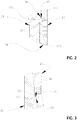
- the embodiment of FIGS. 8-12 is substantially similar to the embodiment of FIGS. 1-7 ( FIGS. 2 and 3 also depict portions 2-2 and 3-3 of the embodiment of FIG. 8 ), with the exception that seal ring 14a is shaped differently than seal ring 14, and corresponding surfaces 29c, 29d of box 15a and pin 16c, respectively, are shaped differently than surfaces 29a, 29b of box 15 and pin 16 ( FIG. 9 depicts portion 9-9 of the embodiment of FIG. 8 ). As such, the differences will be described below with the understanding that the remaining features are substantially similar to those of the first embodiment of FIGS. 1-7 .
- seal ring 14a includes an inner surface (facing the interior of pin 16 and pipe string 10) with a first width (e.g., an outer surface 39a that is parallel to the inner surface, and two lateral surfaces 28c, 28d that each perpendicular to the inner surface and outer surface (resulting in seal ring 14a having a substantially rectangular cross-sectional shape).
- a fillet joins outer surface 39a and lateral surface 28d.
- the connector has a nominal OD of 8 5/8 inches (20.91 cm), and the radial cross-section (as shown in FIG.
- seal ring 14a has a width of 0.75 inches (1.91 cm) and a thickness (between its inner and outer surfaces) of 0.57 inches (1.45 cm).
- the dimensions of seal ring 14a may vary in other embodiments, such as, for example, those with larger-diameter connectors.
- the corresponding surfaces 29c, 29d of box 15a and pin 16a, respectively, are also shaped to align with lateral surfaces 28c, 28d of seal 14a.
- the present embodiments can be used to for high-efficiency, fatigue-resistant, tubular connections in structural connections.
Landscapes
- Engineering & Computer Science (AREA)
- Mining & Mineral Resources (AREA)
- Geology (AREA)
- Life Sciences & Earth Sciences (AREA)
- Mechanical Engineering (AREA)
- Fluid Mechanics (AREA)
- Environmental & Geological Engineering (AREA)
- Physics & Mathematics (AREA)
- General Life Sciences & Earth Sciences (AREA)
- Geochemistry & Mineralogy (AREA)
- General Engineering & Computer Science (AREA)
- Earth Drilling (AREA)
- Gasket Seals (AREA)
Claims (13)
- Système de connecteur (11) comprenant :un composant de broche (16) définissant une zone intérieure creuse avec un premier diamètre interne (DI) sensiblement constant entre une extrémité proximale du composant de broche et une partie d'étanchéité adjacente à une extrémité distale du composant de broche, et ayant une surface extérieure conique avec une pluralité de dents (22), la partie d'étanchéité ayant un second DI qui est plus grand que le premier DI du composant de broche ;un composant de boîtier (15) ayant une surface intérieure conique avec une pluralité de dents (21) configurées pour engrener avec les dents du composant de broche, et ayant une surface extérieure qui comporte une première partie ayant un premier diamètre externe (DE) sensiblement constant s'étendant le long d'une majorité de la longueur du composant de boîtier, et une seconde partie profilée ayant un DE variable qui varie entre la première partie et une extrémité distale (27) du composant de boîtier ;comprenant en outre :une bague d'étanchéité (14) ;où la bague d'étanchéité comprend une surface interne avec une première largeur, une surface externe (39) avec une seconde largeur qui est inférieure à la surface interne, et deux surfaces latérales inclinées (28a, 28b) s'étendant entre la surface interne et la surface externe,caractérisé en ce quela bague d'étanchéité a un DE et est configurée pour être disposée dans la partie d'étanchéité de DI du composant de broche (16) de telle sorte qu'un DE de la bague d'étanchéité (14) vienne en butée contre le second DI du composant de broche.
- Système de connecteur selon la revendication 1, dans lequel les surfaces latérales (28a, 28b) sont à des angles en miroir d'amplitude égale par rapport à un axe qui divise en deux chacune des surfaces supérieure et inférieure.
- Système de connecteur selon l'une quelconque des revendications 1 et 2, dans lequel la partie d'étanchéité du composant de broche comprend une saillie longitudinale annulaire (32) avec une surface radialement interne (39) définissant le second DI.
- Système de connecteur selon la revendication 3, dans lequel une extrémité proximale du composant de boîtier comprend une gorge d'étanchéité de DI longitudinale annulaire (31) conçue pour recevoir la saillie (32) de la partie d'étanchéité de DI.
- Système de connecteur selon la revendication 4, dans lequel la gorge d'étanchéité de DI (31) est conçue pour recevoir la saillie (32) de la partie d'étanchéité de DI avec un ajustement par interférence.
- Système de connecteur selon l'une quelconque des revendications 1 à 5, dans lequel l'extrémité distale du composant de boîtier comprend une partie d'étanchéité de DE ayant un second DE qui est inférieur au premier DE du boîtier pour définir une saillie longitudinale annulaire (38).
- Système de connecteur selon la revendication 6, dans lequel une extrémité proximale du composant de broche comprend une gorge d'étanchéité de DE longitudinale annulaire (35) conçue pour recevoir la saillie (38) de la partie d'étanchéité de DE.
- Système de connecteur selon la revendication 7, dans lequel la gorge d'étanchéité de DE est conçue pour recevoir la saillie longitudinale de la partie d'étanchéité de DE avec un ajustement par interférence.
- Système de connecteur selon l'une quelconque des revendications 1 à 8, dans lequel le DE variable de la seconde partie du composant de boîtier augmente d'abord avec une distance qui le sépare du premier DE de la première partie du composant de boîtier jusqu'à un DE variable maximum, puis diminue avec une distance supplémentaire à partir du premier DE de la première partie jusqu'à un DE variable minimum.
- Système de connecteur selon la revendication 9, dans lequel une paroi latérale du composant de boîtier le long de la partie dans laquelle le DE variable diminue présente une épaisseur sensiblement constante entre le DE variable maximum et la partie d'étanchéité de DI.
- Système de connecteur selon la revendication 9, dans lequel le DE variable minimum est sensiblement égal au premier DE de la première partie du composant de boîtier.
- Système de connecteur selon la revendication 11, dans lequel une paroi latérale du composant de boîtier le long de la partie dans laquelle le DE variable diminue présente une épaisseur sensiblement constante entre le DE variable maximum et la partie d'étanchéité de DI.
- Système de connecteur selon la revendication 12, dans lequel la paroi latérale du composant de boîtier présente une épaisseur sensiblement constante entre le premier DE et la partie d'étanchéité de DI.
Applications Claiming Priority (2)
| Application Number | Priority Date | Filing Date | Title |
|---|---|---|---|
| US201462049947P | 2014-09-12 | 2014-09-12 | |
| PCT/US2015/049782 WO2016040863A1 (fr) | 2014-09-12 | 2015-09-11 | Raccord mécanique dynamique de tube ascenseur |
Publications (3)
| Publication Number | Publication Date |
|---|---|
| EP3191678A1 EP3191678A1 (fr) | 2017-07-19 |
| EP3191678A4 EP3191678A4 (fr) | 2018-04-18 |
| EP3191678B1 true EP3191678B1 (fr) | 2019-10-30 |
Family
ID=55459632
Family Applications (1)
| Application Number | Title | Priority Date | Filing Date |
|---|---|---|---|
| EP15840835.1A Active EP3191678B1 (fr) | 2014-09-12 | 2015-09-11 | Raccord mécanique dynamique de tube ascenseur |
Country Status (7)
| Country | Link |
|---|---|
| US (1) | US10301889B2 (fr) |
| EP (1) | EP3191678B1 (fr) |
| CN (1) | CN107002473B (fr) |
| AU (1) | AU2015314833B2 (fr) |
| BR (1) | BR112017004887B1 (fr) |
| MY (1) | MY184129A (fr) |
| WO (1) | WO2016040863A1 (fr) |
Cited By (1)
| Publication number | Priority date | Publication date | Assignee | Title |
|---|---|---|---|---|
| EP4180617A1 (fr) * | 2021-11-16 | 2023-05-17 | Aquaterra Energy Limited | Raccord de tuyau amélioré |
Families Citing this family (8)
| Publication number | Priority date | Publication date | Assignee | Title |
|---|---|---|---|---|
| US11434699B2 (en) * | 2015-04-16 | 2022-09-06 | Krzysztof Jan Wajnikonis | Mechanical connector of long torsional and bending fatigue life |
| WO2018075669A1 (fr) * | 2016-10-18 | 2018-04-26 | Single Buoy Moorings, Inc. | Connecteur pour colonnes montantes de caténaire en acier |
| CN107345608A (zh) * | 2017-07-31 | 2017-11-14 | 天津大学 | 一种新型水下管道机械连接器 |
| CN111630245B (zh) | 2018-02-02 | 2022-04-12 | 海德里美国分销有限责任公司 | 用于螺纹立管辅助管线的系统和方法 |
| US11125361B2 (en) * | 2018-03-01 | 2021-09-21 | Mitchell Z. Dziekonski | Thread form and threaded article |
| EP3575660B1 (fr) * | 2018-05-29 | 2022-02-23 | Valeo Vyminiky Tepla, s.r.o. | Connecteur servant à connecter deux parties d'un circuit de fluide frigorigène |
| US11555564B2 (en) | 2019-03-29 | 2023-01-17 | Baker Hughes Oilfield Operations Llc | System and method for auxiliary line connections |
| GB201906288D0 (en) * | 2019-05-03 | 2019-06-19 | Oil States Ind Uk Ltd | Pipe coupling |
Family Cites Families (29)
| Publication number | Priority date | Publication date | Assignee | Title |
|---|---|---|---|---|
| US2628111A (en) * | 1948-08-30 | 1953-02-10 | Smalline Harry | Pipe union |
| IT1044052B (it) * | 1974-09-27 | 1980-03-20 | Mannesmann Roehren Werke Ag | Giunto filettato per tubi petroliferi |
| US4426104A (en) * | 1981-10-21 | 1984-01-17 | Nl Industries, Inc. | Underwater connector apparatus |
| US4441740A (en) * | 1981-12-04 | 1984-04-10 | Armco Inc. | Connectors for securing members together under large clamping force |
| DE3412546A1 (de) * | 1983-04-05 | 1984-10-11 | Hunting Oilfield Services (UK) Ltd., Aberdeen | Rohrverbinder |
| US4708376A (en) * | 1986-01-31 | 1987-11-24 | Vetco Gray Inc. | Hydraulic collet-type connector |
| US4815770A (en) * | 1987-09-04 | 1989-03-28 | Cameron Iron Works Usa, Inc. | Subsea casing hanger packoff assembly |
| US4893842A (en) * | 1988-09-27 | 1990-01-16 | Vetco Gray Inc. | Wellhead tieback system with locking dogs |
| AUPM442994A0 (en) * | 1994-03-11 | 1994-04-14 | Australasian Steel Products Pty Ltd | Fluid couplings |
| WO1996029533A1 (fr) * | 1995-03-23 | 1996-09-26 | Hydril Company | Raccord filete pour tubes |
| US5681059A (en) * | 1995-12-15 | 1997-10-28 | Mackie; Michael J. | Pipe connector |
| NO305001B1 (no) * | 1995-12-22 | 1999-03-15 | Abb Offshore Technology As | System og fremgangsmÕte for dykkerfri utskiftning av en driftskomponent pÕ utstyr pÕ en sj°bunnbasert installasjon |
| GB9706084D0 (en) * | 1997-03-24 | 1997-05-14 | Oil States Ind Uk Ltd | Improvements in and relating to pipe connectors |
| GB2335684B (en) * | 1998-03-26 | 2002-07-03 | Vetco Gray Inc Abb | External tieback connector |
| DE10206852B4 (de) * | 2002-02-18 | 2009-02-12 | Walterscheid Rohrverbindungstechnik Gmbh | Kupplung zum Verbinden von Hydraulikleitungen |
| US7011345B2 (en) * | 2002-09-27 | 2006-03-14 | The Lamson & Sessions Co. | Pipe joint and couplers |
| GB2443776B (en) * | 2005-08-23 | 2009-12-09 | Vetco Gray Inc | Preloaded riser coupling system |
| US7686342B2 (en) * | 2005-12-16 | 2010-03-30 | Vetco Gray Inc. | Pipe connector and torque tool |
| US7699354B2 (en) * | 2006-04-28 | 2010-04-20 | Beard Michael E | Marine riser assembly |
| US7878551B2 (en) * | 2006-06-02 | 2011-02-01 | Cameron International Corporation | Subsea choke insert locking apparatus |
| FR2904653B1 (fr) * | 2006-08-02 | 2008-10-10 | Euroslot Soc Par Actions Simpl | Conduit d'extraction articule |
| US7913767B2 (en) * | 2008-06-16 | 2011-03-29 | Vetco Gray Inc. | System and method for connecting tubular members |
| GB2461134A (en) * | 2008-06-27 | 2009-12-30 | Oil States Ind | Pipe connector |
| US20110227338A1 (en) * | 2010-03-22 | 2011-09-22 | Jack Pollack | Sealed pipe joint |
| GB201006336D0 (en) * | 2010-04-15 | 2010-06-02 | Oil States Ind Uk Ltd | Pipe connector device |
| US9234613B2 (en) * | 2010-05-28 | 2016-01-12 | Halliburton Energy Services, Inc. | Well assembly coupling |
| US9097091B2 (en) * | 2011-01-11 | 2015-08-04 | Cameron International Corporation | Subsea retrievable insert with choke valve and non return valve |
| US8757671B2 (en) * | 2011-12-02 | 2014-06-24 | Vetco Gray Inc. | Slide actuating tubular connector |
| USD816811S1 (en) * | 2016-01-25 | 2018-05-01 | Poelsan Plastik Sanayi Ve Ticaret Anonim Sirketi | Pipe joint connection |
-
2015
- 2015-09-11 CN CN201580056701.XA patent/CN107002473B/zh not_active Expired - Fee Related
- 2015-09-11 EP EP15840835.1A patent/EP3191678B1/fr active Active
- 2015-09-11 BR BR112017004887-6A patent/BR112017004887B1/pt active IP Right Grant
- 2015-09-11 WO PCT/US2015/049782 patent/WO2016040863A1/fr not_active Ceased
- 2015-09-11 AU AU2015314833A patent/AU2015314833B2/en not_active Expired - Fee Related
- 2015-09-11 US US15/510,329 patent/US10301889B2/en active Active
- 2015-09-11 MY MYPI2017000386A patent/MY184129A/en unknown
Non-Patent Citations (1)
| Title |
|---|
| None * |
Cited By (1)
| Publication number | Priority date | Publication date | Assignee | Title |
|---|---|---|---|---|
| EP4180617A1 (fr) * | 2021-11-16 | 2023-05-17 | Aquaterra Energy Limited | Raccord de tuyau amélioré |
Also Published As
| Publication number | Publication date |
|---|---|
| US10301889B2 (en) | 2019-05-28 |
| US20170298699A1 (en) | 2017-10-19 |
| BR112017004887A2 (pt) | 2017-12-05 |
| EP3191678A1 (fr) | 2017-07-19 |
| BR112017004887B1 (pt) | 2022-03-03 |
| EP3191678A4 (fr) | 2018-04-18 |
| AU2015314833B2 (en) | 2020-07-16 |
| WO2016040863A1 (fr) | 2016-03-17 |
| MY184129A (en) | 2021-03-19 |
| AU2015314833A1 (en) | 2017-03-30 |
| CN107002473B (zh) | 2019-12-06 |
| CN107002473A (zh) | 2017-08-01 |
Similar Documents
| Publication | Publication Date | Title |
|---|---|---|
| EP3191678B1 (fr) | Raccord mécanique dynamique de tube ascenseur | |
| KR102121628B1 (ko) | 페룰을 갖는 푸시 접속 도관 피팅 | |
| US10557576B2 (en) | Full-root-radius-threaded wing nut having increased wall thickness | |
| EP2372208B1 (fr) | Joint fileté avec bride de joint élastomère | |
| AU2008325839B2 (en) | Threaded joint for steel pipes | |
| NO316044B1 (no) | Gjengeskjöt for rör | |
| RU2722195C2 (ru) | Трубчатый элемент с винтовым упором | |
| US11434699B2 (en) | Mechanical connector of long torsional and bending fatigue life | |
| CN107075925B (zh) | 多用途双抵接部密封连接 | |
| US20220316637A1 (en) | Double taper connector | |
| US8668230B2 (en) | Apparatus and methods for splicing conduits and hoses subsea | |
| EP3405644B1 (fr) | Raccord de tuyau | |
| US9377138B2 (en) | Threaded connections and methods | |
| EP3338017B1 (fr) | Raccord de tuyau flexible | |
| WO2020225545A1 (fr) | Raccord de tuyau |
Legal Events
| Date | Code | Title | Description |
|---|---|---|---|
| STAA | Information on the status of an ep patent application or granted ep patent |
Free format text: STATUS: THE INTERNATIONAL PUBLICATION HAS BEEN MADE |
|
| PUAI | Public reference made under article 153(3) epc to a published international application that has entered the european phase |
Free format text: ORIGINAL CODE: 0009012 |
|
| STAA | Information on the status of an ep patent application or granted ep patent |
Free format text: STATUS: REQUEST FOR EXAMINATION WAS MADE |
|
| 17P | Request for examination filed |
Effective date: 20170313 |
|
| AK | Designated contracting states |
Kind code of ref document: A1 Designated state(s): AL AT BE BG CH CY CZ DE DK EE ES FI FR GB GR HR HU IE IS IT LI LT LU LV MC MK MT NL NO PL PT RO RS SE SI SK SM TR |
|
| AX | Request for extension of the european patent |
Extension state: BA ME |
|
| DAV | Request for validation of the european patent (deleted) | ||
| DAX | Request for extension of the european patent (deleted) | ||
| A4 | Supplementary search report drawn up and despatched |
Effective date: 20180320 |
|
| RIC1 | Information provided on ipc code assigned before grant |
Ipc: E21B 17/046 20060101AFI20180314BHEP Ipc: E21B 17/08 20060101ALI20180314BHEP Ipc: F16L 15/00 20060101ALI20180314BHEP |
|
| GRAP | Despatch of communication of intention to grant a patent |
Free format text: ORIGINAL CODE: EPIDOSNIGR1 |
|
| STAA | Information on the status of an ep patent application or granted ep patent |
Free format text: STATUS: GRANT OF PATENT IS INTENDED |
|
| INTG | Intention to grant announced |
Effective date: 20190425 |
|
| GRAS | Grant fee paid |
Free format text: ORIGINAL CODE: EPIDOSNIGR3 |
|
| GRAA | (expected) grant |
Free format text: ORIGINAL CODE: 0009210 |
|
| STAA | Information on the status of an ep patent application or granted ep patent |
Free format text: STATUS: THE PATENT HAS BEEN GRANTED |
|
| AK | Designated contracting states |
Kind code of ref document: B1 Designated state(s): AL AT BE BG CH CY CZ DE DK EE ES FI FR GB GR HR HU IE IS IT LI LT LU LV MC MK MT NL NO PL PT RO RS SE SI SK SM TR |
|
| REG | Reference to a national code |
Ref country code: GB Ref legal event code: FG4D |
|
| REG | Reference to a national code |
Ref country code: CH Ref legal event code: EP |
|
| REG | Reference to a national code |
Ref country code: AT Ref legal event code: REF Ref document number: 1196322 Country of ref document: AT Kind code of ref document: T Effective date: 20191115 |
|
| REG | Reference to a national code |
Ref country code: DE Ref legal event code: R096 Ref document number: 602015040848 Country of ref document: DE |
|
| REG | Reference to a national code |
Ref country code: IE Ref legal event code: FG4D |
|
| REG | Reference to a national code |
Ref country code: LT Ref legal event code: MG4D |
|
| PG25 | Lapsed in a contracting state [announced via postgrant information from national office to epo] |
Ref country code: NL Free format text: LAPSE BECAUSE OF FAILURE TO SUBMIT A TRANSLATION OF THE DESCRIPTION OR TO PAY THE FEE WITHIN THE PRESCRIBED TIME-LIMIT Effective date: 20191030 Ref country code: SE Free format text: LAPSE BECAUSE OF FAILURE TO SUBMIT A TRANSLATION OF THE DESCRIPTION OR TO PAY THE FEE WITHIN THE PRESCRIBED TIME-LIMIT Effective date: 20191030 Ref country code: LV Free format text: LAPSE BECAUSE OF FAILURE TO SUBMIT A TRANSLATION OF THE DESCRIPTION OR TO PAY THE FEE WITHIN THE PRESCRIBED TIME-LIMIT Effective date: 20191030 Ref country code: NO Free format text: LAPSE BECAUSE OF FAILURE TO SUBMIT A TRANSLATION OF THE DESCRIPTION OR TO PAY THE FEE WITHIN THE PRESCRIBED TIME-LIMIT Effective date: 20200130 Ref country code: GR Free format text: LAPSE BECAUSE OF FAILURE TO SUBMIT A TRANSLATION OF THE DESCRIPTION OR TO PAY THE FEE WITHIN THE PRESCRIBED TIME-LIMIT Effective date: 20200131 Ref country code: PL Free format text: LAPSE BECAUSE OF FAILURE TO SUBMIT A TRANSLATION OF THE DESCRIPTION OR TO PAY THE FEE WITHIN THE PRESCRIBED TIME-LIMIT Effective date: 20191030 Ref country code: LT Free format text: LAPSE BECAUSE OF FAILURE TO SUBMIT A TRANSLATION OF THE DESCRIPTION OR TO PAY THE FEE WITHIN THE PRESCRIBED TIME-LIMIT Effective date: 20191030 Ref country code: BG Free format text: LAPSE BECAUSE OF FAILURE TO SUBMIT A TRANSLATION OF THE DESCRIPTION OR TO PAY THE FEE WITHIN THE PRESCRIBED TIME-LIMIT Effective date: 20200130 Ref country code: PT Free format text: LAPSE BECAUSE OF FAILURE TO SUBMIT A TRANSLATION OF THE DESCRIPTION OR TO PAY THE FEE WITHIN THE PRESCRIBED TIME-LIMIT Effective date: 20200302 Ref country code: FI Free format text: LAPSE BECAUSE OF FAILURE TO SUBMIT A TRANSLATION OF THE DESCRIPTION OR TO PAY THE FEE WITHIN THE PRESCRIBED TIME-LIMIT Effective date: 20191030 |
|
| REG | Reference to a national code |
Ref country code: NL Ref legal event code: MP Effective date: 20191030 |
|
| PG25 | Lapsed in a contracting state [announced via postgrant information from national office to epo] |
Ref country code: RS Free format text: LAPSE BECAUSE OF FAILURE TO SUBMIT A TRANSLATION OF THE DESCRIPTION OR TO PAY THE FEE WITHIN THE PRESCRIBED TIME-LIMIT Effective date: 20191030 Ref country code: IS Free format text: LAPSE BECAUSE OF FAILURE TO SUBMIT A TRANSLATION OF THE DESCRIPTION OR TO PAY THE FEE WITHIN THE PRESCRIBED TIME-LIMIT Effective date: 20200229 Ref country code: HR Free format text: LAPSE BECAUSE OF FAILURE TO SUBMIT A TRANSLATION OF THE DESCRIPTION OR TO PAY THE FEE WITHIN THE PRESCRIBED TIME-LIMIT Effective date: 20191030 |
|
| PG25 | Lapsed in a contracting state [announced via postgrant information from national office to epo] |
Ref country code: AL Free format text: LAPSE BECAUSE OF FAILURE TO SUBMIT A TRANSLATION OF THE DESCRIPTION OR TO PAY THE FEE WITHIN THE PRESCRIBED TIME-LIMIT Effective date: 20191030 |
|
| PG25 | Lapsed in a contracting state [announced via postgrant information from national office to epo] |
Ref country code: DK Free format text: LAPSE BECAUSE OF FAILURE TO SUBMIT A TRANSLATION OF THE DESCRIPTION OR TO PAY THE FEE WITHIN THE PRESCRIBED TIME-LIMIT Effective date: 20191030 Ref country code: EE Free format text: LAPSE BECAUSE OF FAILURE TO SUBMIT A TRANSLATION OF THE DESCRIPTION OR TO PAY THE FEE WITHIN THE PRESCRIBED TIME-LIMIT Effective date: 20191030 Ref country code: ES Free format text: LAPSE BECAUSE OF FAILURE TO SUBMIT A TRANSLATION OF THE DESCRIPTION OR TO PAY THE FEE WITHIN THE PRESCRIBED TIME-LIMIT Effective date: 20191030 Ref country code: RO Free format text: LAPSE BECAUSE OF FAILURE TO SUBMIT A TRANSLATION OF THE DESCRIPTION OR TO PAY THE FEE WITHIN THE PRESCRIBED TIME-LIMIT Effective date: 20191030 Ref country code: CZ Free format text: LAPSE BECAUSE OF FAILURE TO SUBMIT A TRANSLATION OF THE DESCRIPTION OR TO PAY THE FEE WITHIN THE PRESCRIBED TIME-LIMIT Effective date: 20191030 |
|
| REG | Reference to a national code |
Ref country code: DE Ref legal event code: R097 Ref document number: 602015040848 Country of ref document: DE |
|
| REG | Reference to a national code |
Ref country code: AT Ref legal event code: MK05 Ref document number: 1196322 Country of ref document: AT Kind code of ref document: T Effective date: 20191030 |
|
| PG25 | Lapsed in a contracting state [announced via postgrant information from national office to epo] |
Ref country code: IT Free format text: LAPSE BECAUSE OF FAILURE TO SUBMIT A TRANSLATION OF THE DESCRIPTION OR TO PAY THE FEE WITHIN THE PRESCRIBED TIME-LIMIT Effective date: 20191030 Ref country code: SK Free format text: LAPSE BECAUSE OF FAILURE TO SUBMIT A TRANSLATION OF THE DESCRIPTION OR TO PAY THE FEE WITHIN THE PRESCRIBED TIME-LIMIT Effective date: 20191030 Ref country code: SM Free format text: LAPSE BECAUSE OF FAILURE TO SUBMIT A TRANSLATION OF THE DESCRIPTION OR TO PAY THE FEE WITHIN THE PRESCRIBED TIME-LIMIT Effective date: 20191030 |
|
| PLBE | No opposition filed within time limit |
Free format text: ORIGINAL CODE: 0009261 |
|
| STAA | Information on the status of an ep patent application or granted ep patent |
Free format text: STATUS: NO OPPOSITION FILED WITHIN TIME LIMIT |
|
| 26N | No opposition filed |
Effective date: 20200731 |
|
| PG25 | Lapsed in a contracting state [announced via postgrant information from national office to epo] |
Ref country code: SI Free format text: LAPSE BECAUSE OF FAILURE TO SUBMIT A TRANSLATION OF THE DESCRIPTION OR TO PAY THE FEE WITHIN THE PRESCRIBED TIME-LIMIT Effective date: 20191030 Ref country code: AT Free format text: LAPSE BECAUSE OF FAILURE TO SUBMIT A TRANSLATION OF THE DESCRIPTION OR TO PAY THE FEE WITHIN THE PRESCRIBED TIME-LIMIT Effective date: 20191030 |
|
| REG | Reference to a national code |
Ref country code: DE Ref legal event code: R119 Ref document number: 602015040848 Country of ref document: DE |
|
| PG25 | Lapsed in a contracting state [announced via postgrant information from national office to epo] |
Ref country code: MC Free format text: LAPSE BECAUSE OF FAILURE TO SUBMIT A TRANSLATION OF THE DESCRIPTION OR TO PAY THE FEE WITHIN THE PRESCRIBED TIME-LIMIT Effective date: 20191030 |
|
| REG | Reference to a national code |
Ref country code: CH Ref legal event code: PL |
|
| REG | Reference to a national code |
Ref country code: BE Ref legal event code: MM Effective date: 20200930 |
|
| PG25 | Lapsed in a contracting state [announced via postgrant information from national office to epo] |
Ref country code: LU Free format text: LAPSE BECAUSE OF NON-PAYMENT OF DUE FEES Effective date: 20200911 |
|
| PG25 | Lapsed in a contracting state [announced via postgrant information from national office to epo] |
Ref country code: DE Free format text: LAPSE BECAUSE OF NON-PAYMENT OF DUE FEES Effective date: 20210401 |
|
| PG25 | Lapsed in a contracting state [announced via postgrant information from national office to epo] |
Ref country code: CH Free format text: LAPSE BECAUSE OF NON-PAYMENT OF DUE FEES Effective date: 20200930 Ref country code: BE Free format text: LAPSE BECAUSE OF NON-PAYMENT OF DUE FEES Effective date: 20200930 Ref country code: LI Free format text: LAPSE BECAUSE OF NON-PAYMENT OF DUE FEES Effective date: 20200930 Ref country code: IE Free format text: LAPSE BECAUSE OF NON-PAYMENT OF DUE FEES Effective date: 20200911 |
|
| PG25 | Lapsed in a contracting state [announced via postgrant information from national office to epo] |
Ref country code: TR Free format text: LAPSE BECAUSE OF FAILURE TO SUBMIT A TRANSLATION OF THE DESCRIPTION OR TO PAY THE FEE WITHIN THE PRESCRIBED TIME-LIMIT Effective date: 20191030 Ref country code: MT Free format text: LAPSE BECAUSE OF FAILURE TO SUBMIT A TRANSLATION OF THE DESCRIPTION OR TO PAY THE FEE WITHIN THE PRESCRIBED TIME-LIMIT Effective date: 20191030 Ref country code: CY Free format text: LAPSE BECAUSE OF FAILURE TO SUBMIT A TRANSLATION OF THE DESCRIPTION OR TO PAY THE FEE WITHIN THE PRESCRIBED TIME-LIMIT Effective date: 20191030 |
|
| PG25 | Lapsed in a contracting state [announced via postgrant information from national office to epo] |
Ref country code: MK Free format text: LAPSE BECAUSE OF FAILURE TO SUBMIT A TRANSLATION OF THE DESCRIPTION OR TO PAY THE FEE WITHIN THE PRESCRIBED TIME-LIMIT Effective date: 20191030 |
|
| P01 | Opt-out of the competence of the unified patent court (upc) registered |
Effective date: 20230525 |
|
| PGFP | Annual fee paid to national office [announced via postgrant information from national office to epo] |
Ref country code: GB Payment date: 20250820 Year of fee payment: 11 |
|
| PGFP | Annual fee paid to national office [announced via postgrant information from national office to epo] |
Ref country code: FR Payment date: 20250821 Year of fee payment: 11 |