EP3191723B1 - Ensemble de renforcement - Google Patents
Ensemble de renforcement Download PDFInfo
- Publication number
- EP3191723B1 EP3191723B1 EP15778996.7A EP15778996A EP3191723B1 EP 3191723 B1 EP3191723 B1 EP 3191723B1 EP 15778996 A EP15778996 A EP 15778996A EP 3191723 B1 EP3191723 B1 EP 3191723B1
- Authority
- EP
- European Patent Office
- Prior art keywords
- stiffening assembly
- modules
- main
- fastening
- article
- Prior art date
- Legal status (The legal status is an assumption and is not a legal conclusion. Google has not performed a legal analysis and makes no representation as to the accuracy of the status listed.)
- Active
Links
Images



Classifications
-
- E—FIXED CONSTRUCTIONS
- E04—BUILDING
- E04B—GENERAL BUILDING CONSTRUCTIONS; WALLS, e.g. PARTITIONS; ROOFS; FLOORS; CEILINGS; INSULATION OR OTHER PROTECTION OF BUILDINGS
- E04B1/00—Constructions in general; Structures which are not restricted either to walls, e.g. partitions, or floors or ceilings or roofs
- E04B1/62—Insulation or other protection; Elements or use of specified material therefor
- E04B1/92—Protection against other undesired influences or dangers
- E04B1/98—Protection against other undesired influences or dangers against vibrations or shocks; against mechanical destruction, e.g. by air-raids
-
- F—MECHANICAL ENGINEERING; LIGHTING; HEATING; WEAPONS; BLASTING
- F16—ENGINEERING ELEMENTS AND UNITS; GENERAL MEASURES FOR PRODUCING AND MAINTAINING EFFECTIVE FUNCTIONING OF MACHINES OR INSTALLATIONS; THERMAL INSULATION IN GENERAL
- F16B—DEVICES FOR FASTENING OR SECURING CONSTRUCTIONAL ELEMENTS OR MACHINE PARTS TOGETHER, e.g. NAILS, BOLTS, CIRCLIPS, CLAMPS, CLIPS OR WEDGES; JOINTS OR JOINTING
- F16B7/00—Connections of rods or tubes, e.g. of non-circular section, mutually, including resilient connections
- F16B7/20—Connections of rods or tubes, e.g. of non-circular section, mutually, including resilient connections using bayonet connections
-
- E—FIXED CONSTRUCTIONS
- E04—BUILDING
- E04B—GENERAL BUILDING CONSTRUCTIONS; WALLS, e.g. PARTITIONS; ROOFS; FLOORS; CEILINGS; INSULATION OR OTHER PROTECTION OF BUILDINGS
- E04B9/00—Ceilings; Construction of ceilings, e.g. false ceilings; Ceiling construction with regard to insulation
- E04B9/18—Means for suspending the supporting construction
-
- E—FIXED CONSTRUCTIONS
- E04—BUILDING
- E04H—BUILDINGS OR LIKE STRUCTURES FOR PARTICULAR PURPOSES; SWIMMING OR SPLASH BATHS OR POOLS; MASTS; FENCING; TENTS OR CANOPIES, IN GENERAL
- E04H9/00—Buildings, groups of buildings or shelters adapted to withstand or provide protection against abnormal external influences, e.g. war-like action, earthquake or extreme climate
- E04H9/02—Buildings, groups of buildings or shelters adapted to withstand or provide protection against abnormal external influences, e.g. war-like action, earthquake or extreme climate withstanding earthquake or sinking of ground
-
- F—MECHANICAL ENGINEERING; LIGHTING; HEATING; WEAPONS; BLASTING
- F16—ENGINEERING ELEMENTS AND UNITS; GENERAL MEASURES FOR PRODUCING AND MAINTAINING EFFECTIVE FUNCTIONING OF MACHINES OR INSTALLATIONS; THERMAL INSULATION IN GENERAL
- F16B—DEVICES FOR FASTENING OR SECURING CONSTRUCTIONAL ELEMENTS OR MACHINE PARTS TOGETHER, e.g. NAILS, BOLTS, CIRCLIPS, CLAMPS, CLIPS OR WEDGES; JOINTS OR JOINTING
- F16B37/00—Nuts or like thread-engaging members
- F16B37/08—Quickly-detachable or mountable nuts, e.g. consisting of two or more parts; Nuts movable along the bolt after tilting the nut
- F16B37/0871—Quickly-detachable or mountable nuts, e.g. consisting of two or more parts; Nuts movable along the bolt after tilting the nut engaging the bolt laterally, i.e. without the need to engage the end of the bolt
- F16B37/0878—Quickly-detachable or mountable nuts, e.g. consisting of two or more parts; Nuts movable along the bolt after tilting the nut engaging the bolt laterally, i.e. without the need to engage the end of the bolt in one piece, e.g. C-shaped nuts
-
- F—MECHANICAL ENGINEERING; LIGHTING; HEATING; WEAPONS; BLASTING
- F21—LIGHTING
- F21S—NON-PORTABLE LIGHTING DEVICES; SYSTEMS THEREOF; VEHICLE LIGHTING DEVICES SPECIALLY ADAPTED FOR VEHICLE EXTERIORS
- F21S8/00—Lighting devices intended for fixed installation
- F21S8/04—Lighting devices intended for fixed installation intended only for mounting on a ceiling or the like overhead structures
- F21S8/06—Lighting devices intended for fixed installation intended only for mounting on a ceiling or the like overhead structures by suspension
- F21S8/063—Lighting devices intended for fixed installation intended only for mounting on a ceiling or the like overhead structures by suspension with a rigid pendant, i.e. a pipe or rod
-
- F—MECHANICAL ENGINEERING; LIGHTING; HEATING; WEAPONS; BLASTING
- F21—LIGHTING
- F21V—FUNCTIONAL FEATURES OR DETAILS OF LIGHTING DEVICES OR SYSTEMS THEREOF; STRUCTURAL COMBINATIONS OF LIGHTING DEVICES WITH OTHER ARTICLES, NOT OTHERWISE PROVIDED FOR
- F21V21/00—Supporting, suspending, or attaching arrangements for lighting devices; Hand grips
- F21V21/008—Suspending from a cable or suspension line
Definitions
- This invention relates to stiffening assemblies. More particularly, but not exclusively, this invention relates to rod stiffening assemblies. Embodiments of the invention relate to stiffening assemblies for use in stiffening elongate articles, such as rods, during seismic events.
- US 8047478 B1 discloses a modular post system with holes on multiple axial planes.
- a stiffening assembly for stiffening an article, the stiffening assembly comprising a plurality of main modules arrangeable on the article, each main module comprising:
- Each of the main modules may define a plane extending longitudinally through the outer opening and through said axis, wherein the planes defined by the modules are each in a substantially identical position relative to the respective module, and wherein the planes of adjacent modules are disposed relative to each other at an angle of between 1° and 24°.
- the planes of adjacent modules may be disposed relative to each other at an angle of between 1° and 12°.
- the planes of adjacent modules may be disposed relative to each other at an angle of between 5° and 10°.
- the planes of adjacent modules may be disposed relative to each other at an angle of between 8° and 9°.
- the planes of adjacent modules may be disposed relative to each other at an angle of substantially 8.5°.
- the planes of adjacent modules may be disposed relative to each other at an angle of between 2° and 23°.
- the planes of adjacent modules may be disposed relative to each other at an angle of between 10° and 20°.
- the planes of adjacent modules may be disposed relative to each other at an angle of between 16° and 18°.
- the planes of adjacent modules may be disposed relative to each other at an angle of substantially 17°.
- the stiffening assembly may further include a securing arrangement for securing the main modules to the article.
- the stiffening assembly may be suitable for use with an elongate article, for example a rod.
- the stiffening assembly may be suitable for use during seismic events.
- the stiffening assembly may comprise a seismic protection stiffening assembly.
- the stiffening assembly may be elongate.
- the stiffening assembly may comprise a fastening arrangement for coupling the main modules to one another.
- the fastening arrangement may comprise first and second fastening formations.
- the first fastening formations may comprise male fastening formations.
- the second fastening formations may comprise female fastening formations to receive the male fastening formations.
- the first and second fastening formations may be threaded fastening formations.
- the first fastening formations may comprises externally threaded fastening formations.
- the second fastening formations may comprise internally threaded fastening formations.
- the receiving formation may be provided within the body.
- the body may have an internal region.
- the internal region may define the internal space for receiving the article therethrough, the internal space may be defined by the body.
- the receiving formation may have opposite open ends to allow the article to extend through the internal space.
- the receiving formation may be elongate.
- the internal space may be elongate.
- the receiving formation may extend through the body.
- the internal space may extend centrally through the body.
- the internal space may extend substantially along the central axis of the body.
- the receiving formation may extend substantially centrally through the body.
- the receiving formation may be tubular.
- the receiving formation may have a substantially circular end profile.
- the receiving formation may have a substantially U shaped profile.
- the internal space defined by said receiving formation may have a substantially circular end profile.
- the internal space defined by said receiving formation may have a substantially U shaped end profile.
- the internal space may be elongate.
- the outer opening may allow access to the internal space.
- the outer opening may extend the whole length of the body.
- the outer opening may be a slot.
- the receiving formation may define an inner opening to allow said portion of the article to be received within the internal space.
- the inner opening may be elongate and may extend the whole length of the receiving formation.
- the inner opening may be a further slot in the receiving formation.
- the body may define a guide passage to guide the article to the inner opening defined by the receiving formation.
- the guide passage may be configured to guide the article between the inner opening and the outer opening.
- the body may comprise opposed walls extending between the inner opening and the outer opening. The opposed walls may define the guide passage.
- first and second fastening formations may be provided on a respective one of the opposite ends.
- the first fastening formation on one of the main modules may co-operate engagingly with the second fastening formation on an adjacent one of the main modules to couple the main modules to each other.
- the first fastening formation on one of the main modules may be rotatably moveable relative to the second fastening formation on the adjacent main module.
- co-operative engagement of the first fastening formation on one of the main modules with the second fastening formation on the adjacent main module is effected by rotation of the first and second fastening formations relative to each other.
- the aforesaid rotation may be effected by rotating the body of the adjacent main modules relative to each other.
- Said rotation can be effected about the longitudinal main central axis of the body of each main module.
- the longitudinal subsidiary central axis of the receiving formation may extend substantially parallel to the main central axis of the body.
- the offset of the longitudinal subsidiary central axis of the receiving formation from the main central axis of the body provides the advantage in one embodiment described herein that, when adjacent main modules are coupled to each other by relative rotation, the respective receiving formations are moved to positions in which they are unaligned relative to each other, thereby securing the main modules to the article.
- the securing arrangement may comprise the fastening arrangement.
- the securing arrangement may further include receiving formation of each main module.
- the first and second fastening formations on each end of the body may comprise corresponding first and second threaded portions to allow adjacent main modules to be coupled to one another by screwing them together.
- the threaded portions may be provided at respective opposite ends of the body.
- the first threaded portion may be externally threaded.
- the second threaded portion may be internally threaded.
- the fastening arrangement may comprise a coupling module to couple the main modules to one another.
- the fastening arrangement may comprise a plurality of coupling modules.
- the first and second fastening formations may be provided respectively on the main and coupling modules.
- the main module may comprise at least one of the first fastening formations. Desirably, the main module may have two of the first fastening formations.
- the body may have a first fastening formation at each of the opposite ends thereof. The first fastening formations may be coaxially aligned with each other.
- Each coupling module may have a second fastening formation.
- Each of the coupling modules may have two fastening formations. Both fastening formations of each coupling module may be second fastening formations. The second fastening formations may be coaxially aligned with each other.
- each main module may comprise two male first fastening formations.
- the coupling module may comprise two female second fastening formations.
- the stiffening assembly may comprise a plurality of main modules, wherein the body of each main module has two first fastening formations.
- the stiffening assembly may further include a respective coupling module to couple two of the main modules in an adjacent aligned relationship, the coupling formation having two second fastening formations.
- Each coupling module may comprise a holding portion provided between the fastening formations of the coupling module.
- the holding portion may define an aperture having a side opening.
- the side opening may extend the length of the coupling module to allow access for the article to the aperture.
- the aperture may be configured to receive the article therethrough.
- the aperture may have a substantially U shaped end profile.
- the receiving formation may comprise inner projections extending into the internal space.
- the projections may be configured to engage the article when the article is received in the internal space.
- the projections may allow the stiffening assembly to be used with articles of differing diameters.
- the projections may be configured to be crushed by the article. This can be the case where the article has a larger diameter.
- the holding formation may comprise inner projecting members extending into the aperture.
- the inner projecting members may be configured to engage the article when the article is received in the aperture.
- the first and second fastening formations may comprise bayonet fittings.
- Each bayonet fitting may comprise a radially extending projecting portion on one of the main module and the coupling module.
- Each bayonet fittings may comprise a circumferentially extending channel on the other of the main module and the coupling module.
- the first fastening formation may comprise the circumferentially extending channel.
- the channel may extend radially outwardly.
- the second fastening formation may comprise the projecting portion.
- the projecting portion may extend radially inwardly.
- Each first fastening formation may comprise a substantially cylindrical portion.
- Each main module may comprise a pair of substantially cylindrical portions, wherein each substantially cylindrical portion may be provided at a respective opposite end of the body.
- Each first fastening formation may further include a first securing arrangement.
- the first securing arrangement may comprise a first part of the bayonet fitting.
- the first securing arrangement may comprise the channel.
- the channel may extend circumferentially around the cylindrical portion.
- the first securing arrangement may include a stop member at one end of the channel.
- the stop member may be in the form of walls extending across the channel.
- Each coupling module may comprise a pair of opposed second fastening formations.
- Each of the second fastening formations may be in the form of a female fastening formation.
- Each of the second fastening formations may comprise a socket formation.
- Each socket formation may comprise a hollow cylindrical portion.
- Each socket formation may further include a radially inwardly extending second securing arrangement.
- Each second securing arrangement may comprise second parts of the bayonet fitting.
- the second fastening formations may be axially aligned with each other.
- the first and second securing arrangements may be twisted relative to each other to secure the main modules in an unaligned relationship when the main modules are coupled to one another to form the stiffening assembly.
- Adjacent main modules in said stiffening assembly may be twisted relative to each other by an angle of greater than 90°.
- Adjacent main modules in said stiffening assembly may be twisted relative to each other by an angle of between 182° and 204°.
- Adjacent main modules in said stiffening assembly may be twisted relative to each other by an angle of between 185° and 200°, Adjacent main modules in said stiffening assembly may be twisted relative to each other by an angle of between 196° and 198°, for example substantially 197°.
- Each main module may be twisted by an angle of between 91° and 102° relative to the, or each, coupling module to which it is secured. Each main module may be twisted by an angle of between 95° and 100° relative to the, or each, coupling module to which it is secured, Each main module may be twisted by an angle of between 98° and 99° relative to the, or each, coupling module to which it is secured, for example substantially 98.5°.
- Alternate main modules of the stiffening assembly may be twisted relative to each other by an angle of between 364° and 408°. Alternate main modules of the stiffening assembly may be disposed relative to each other by an angle of between 4° and 48°.
- Alternate main modules of the stiffening assembly may be twisted relative to each other by an angle of between 380° and 400°. Alternate main modules of the stiffening assembly may be disposed relative to each other by an angle of between 20° and 40°.
- Alternate main modules of the stiffening assembly may be twisted relative to each other by an angle of between 392° and 396°, for example substantially 394°. Alternate main modules of the stiffening assembly may be disposed relative to each other by an angle of between 32° and 36 °, for example substantially 34°.
- the stop member and/or the second part may be positioned so that when a plurality the main modules are coupled to one another by means of the coupling modules, the adjacent main modules and coupling modules may be rotated relative to each other by between 91° and 102°. In a stiffening assembly, the adjacent main modules and coupling modules may be rotated relative to each other by between 91° and 98°.
- the stop member and/or the second part may be positioned so that when a plurality the main modules are coupled to one another by means of the coupling modules, the adjacent main modules and coupling modules are rotated relative to each other by between 95° and 100°.
- the adjacent main modules and coupling modules may be rotated relative to each other by between 92° and 96°.
- the stop member and/or the second part may be positioned so that when a plurality the main modules are coupled to one another by means of the coupling modules, the adjacent main modules and coupling modules are rotated relative to each other by between 98° and 99°, for example 98.5°. In a stiffening assembly, the adjacent main modules and coupling modules are rotated relative to each other by between 93° and 95°, for example, between 94° and 94.5°.
- Adjacent main modules may be between 182° and 204° out of alignment with each other. In a stiffening assembly, the adjacent main modules may be between 182° and 196° out of alignment with each other.
- Adjacent main modules may be between 190° and 200° out of alignment with each other.
- the adjacent main modules may be between 184° and 192° out of alignment with each other.
- Adjacent main modules may be between 196° and 198° out of alignment with each other, for example 197°. Adjacent main modules may be between 186° and 190° out of alignment with each other, for example between 188° and 189°.
- Alternate main modules may be between 4° and 48° out of alignment with each other. Alternate main modules may be between 20° and 40° out of alignment with each other. Alternate main modules may be between 32° and 36° out of alignment with each other, for example 34° out of alignment with each other.
- alternate main modules may be between 2° and 24° out of alignment with each other.
- Alternate main modules may be between 10° and 20° out of alignment with each other.
- Alternate main modules may be between 16° and 18° out of alignment with each other, for example substantially 17° out of alignment with each other.
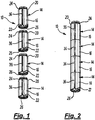
- Figures 1 to 4 of the drawings show an embodiment of a stiffening assembly 10 for stiffening an elongate article in the form of a rod 12.
- the elongate article may be threaded and may comprise a threaded rod.
- the stiffening assembly 10 comprises a plurality of main modules 14 which can receive the rod 12 therethrough.
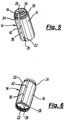
- FIGs 5 to 8 show an individual one of the main modules 14.
- Each of the main modules 14 comprises a substantially cylindrical body 16 having a longitudinal main central axis 18 (see Figures 7 and 8 ) extending along the longitudinal centre line of the body 16.
- the cylindrical body 16 also has opposite ends 20, 22 (see Figures 5 and 6 ).
- Each main module 14 also includes first and second fastening formations 24, 26 provided respectively on the opposite ends 20, 22.
- the first fastening formation 24 comprises an externally threaded portion extending axially from the body 16.
- the second fastening formation 26 comprises an internally threaded portion extending axially from the body 16.
- the first fastening formation 24 on each main module 14 can be received by the second fastening formation 26 of the adjacent main module 14 to couple the adjacent main modules 14 to each other (see Figures 2 to 4 ).
- the adjacent main modules 14 are rotated relative to each other about their central main axes 18 to screw the first fastening formations 24 into the second fastening formations 26, thereby fastening the adjacent main modules 14 to each other.
- Each main module 14 comprises a receiving formation provided centrally within the body 16.
- the receiving formation is in the form of a substantially cylindrical tubular member 28 defining an elongate substantially cylindrical internal space 30.
- the tubular member 28 has a longitudinal subsidiary central axis 32 extending along the longitudinal centre line of the tubular member 28.
- the longitudinal subsidiary central axis 32 is substantially parallel to the main central axis 18 of the body 16.
- the longitudinal subsidiary central axis 32 of the tubular member 28 is offset from the main central axis 18 of the body 16.
- the tubular member 28 is offset from the main central axis 18 of the body 16. The reason for this is explained below.
- the tubular member 28 has an elongate inner opening 34 in the form of a first slot.
- the elongate inner opening 34 extends the whole length of the tubular member 38.
- the body 16 defines an elongate outer opening 36 in the form of a second slot.
- the elongate outer opening 36 extends the whole length of the body 16 and is aligned with the inner opening 34 defined in the tubular member 28.
- the rod 12 can be received in the internal space 30 via the inner and outer openings 34, 36.
- a guide formation 38 is provided between the inner opening 34 and the outer opening 36.
- the guide formation 38 comprises a pair of parallel walls 40 extending from the tubular member 28 to the body 16.
- the parallel walls 40 define a guide passage 42 therebetween.
- the guide passage 42 guides the rod 12 from the elongate outer opening 36 via the inner opening 34 to the internal space 30 defined by the tubular member 28.
- a plurality of straightening formations 44 in the form of substantially planar members extend from the body 16 to the tubular member 28.
- a plurality of the main modules 14 can be mounted on the rod 12 by passing the rod 12 into each of the main modules 14.
- the rod 12 passes through the elongate outer opening 36 of each main module 14 to the elongate internal space 30 via the guide passage 42 and the inner opening 34.
- a desired number of the main modules 14, for example 4 can be provided on the rod 12, with the rod 12 extending through the tubular members 28 of all of the main modules 14.
- the main modules 14 can be secured to the rod 12 by screwing the first fastening formations 24 into the second fastening formations 26 of the adjacent main modules 14.
- the tubular members 28 are moved to positions where the central axes 32 are not aligned with each other. This causes the tubular members 28 to be offset from one another thereby causing the tubular members 28 to engage tightly with the rod 12.
- the fastening formations 24, 26 and the offset tubular members 28 constitute a securing arrangement for securing the stiffening assembly 10 to the rod 12.
- the main modules 14 are secured to the rod 12.
- stiffening assembly 10 which can be used for stiffening an elongate article in the form of a rod.
- the stiffening assembly 10 has the advantage that it can be used for seismic protection in areas prone to earthquakes to reduce the flexibility of the rods when earthquakes occur.
- the stiffening assembly 10 has the advantage that it can be used for blast protection, for example in embassies, or in military or government facilities. It also has the advantage of being suitable for use for force protection, for example in the case of hurricanes or tornadoes.
- FIGS 9 to 16 show another stiffening assembly, generally designated 110, for stiffening the rod 12.
- the stiffening assembly 110 comprises a plurality of main modules 114, each having a substantially cylindrical body 116.
- the substantially cylindrical body 116 has a central main axis 118 (see Figures 12 and 16 ) which extends longitudinally through the body 116.
- the cylindrical body 116 also has opposite ends 120, 122.
- Each main module 114 also includes a respective first fastening formation 124 extending axially from each of the opposite ends 120, 122.
- the first fastening formation 124 comprises a projecting formation in the form of a male fastening formation.
- Each first fastening formation 124 comprises a substantially cylindrical portion 126 extending axially from the body 116.
- Each first fastening formation 124 further includes an outwardly projecting first securing arrangement 128 comprising first parts of a bayonet fitting.
- the first securing arrangements 128 are in the form of channels 129, which extend circumferentially around the cylindrical portions 126.
- the first securing arrangements 128 include stop members 131 at one end of each channel 129, the purpose of which is described below.
- the stop members 131 are in the form of walls extending across the channels 129.
- the stiffening assembly 110 further includes a plurality of coupling modules 130 to couple the main modules 114 to one another when the main modules 114 and the coupling modules 130 are mounted on the rod 12. Gaps 129A are defined between the channels 129 to receive second parts 138 (see below) of the bayonet fitting when the main module 114 is secured to the coupling module 130.
- the second parts 138 are in the form radially inwardly extending projections.
- Each coupling module 130 comprises a pair of opposed second fastening formations 132.
- Each of the second fastening formations 132 is in the form of a female fastening formation.
- Each of the second fastening formations 132 comprises a socket formation in the form of a hollow cylindrical portion 134 and a radially inwardly extending second securing arrangement 136 in the form of the second parts 138 of the bayonet fitting.
- the second fastening formations 132 are axially aligned with each other.
- Each coupling module 130 has a central main axis 139 (see Figure 14 )
- first and second fastening formations 128, 132 may comprise corresponding threads on the cylindrical portions 126, 134.
- Each of the main modules 114 has a receiving formation 140 comprising an elongate axially extending member 142 defining an elongate recess 144 extending inwardly from an elongate opening 146 extending the length of the body 116.
- the recess 144 extends from the opening 146 to a region beyond the central main axis 118 of the main module 114 and can receive the rod 12 therethrough.
- the recess 144 and the opening 146 also extend through the first fastening arrangements 124.
- the rod 12 can be inserted into the recess 144 via the opening 146.
- the receiving formation 140 includes a plurality of inner projections in the form of gripping elements 148 projecting inwardly from the axially extending member into the recess 144.
- the function of the gripping elements 148 is to engage the rod 12 when it is inserted into the recess.
- Each of the coupling modules 130 has a holding portion 150 between the opposed second fastening formations 132.
- the holding portion comprises a separator 152, which separates the second fastening formations 132 from each other.
- the hollow cylindrical portions 134 define an opening 154 which extends the whole length of the coupling module 130.
- the separator 152 defines a recess 156 which extends across the separator 152 from the opening 154 to a region beyond the central main axis 139 of the coupling module 130.
- the recess 156 can receive the rod 12 therein.
- the rod 12 can be inserted into the recess 156 via the opening 146.
- the holding portion 150 includes a plurality of inner projecting members in the form of gripping elements 158 projecting inwardly from the separator 152 into the recess 156.
- the function of the gripping elements 158 is the same as the function of the gripping elements 148, i.e. to engage the rod 12 when it is inserted into the recess 156.
- the gripping elements 148, 158 provide the advantage that they allow rods 12 of different diameters to be held in the receiving formation 140. In the case of larger diameter rods 12, the gripping elements 148, 158 are crushed by the rod 12 when it is received in the recess 144 and the modules 114, 130 rotated relative to each other to secure them together (see below). In the case of smaller diameter rods 12, the gripping elements 148, 158 simply engage the rod 12.
- the stiffening assembly 110 is arranged on the rod 12, so that the rod 12 is received in the recesses 144, 156 and is engaged by the gripping elements 148, 158.
- the main modules 114 and the coupling modules 130 are arranged so that their central main axes 118, 139 are aligned with each other. When so received, the rod 12 extends along the central main axes 118, 139.
- the main modules 114 When the stiffening assembly 110 is assembled, the main modules 114 alternate with respect to the coupling modules 130.
- the first fastening arrangements 128 of the main modules 114 are received within the second fastening arrangements 132 of the coupling modules 130, as shown in Figure 10 .
- the inwardly extending second parts 138 of the bayonet fitting are received in the gaps 129A between the channels 129.
- the main modules 114 and the coupling modules 130 can then be rotated or twisted, for example by 90°, relative to each other about the central main axis 118, as shown by the arrows A and B in Figure 10 , to the positions shown in Figure 11 .
- the first and second fastening arrangements 128, 132 cooperate with each other, so that the inwardly extending second parts 138 move along the channels 129 until the inwardly extending second parts engage the stop members 131.
- the main modules 114 are secured to the coupling modules 130.
- the main modules 114 are coupled to one another by means of the coupling modules 130.
- the lengths of the main modules 114 and of the coupling modules 130 are selected to provide the maximum coverage of any length of the rod 12 leaving a minimum length of the rod protruding from the ends of the stiffening assembly 110.
- the user can choose the number of main modules 114 and coupling modules 130, and whether or not coupling modules 130 are provided at the top or bottom of the stiffening assembly 110.
- the provision of the main modules 114 and the coupling modules 130 of different lengths allows as much as possible of the length of the rod 12 to be covered by the stiffening assembly 110.
- the stiffening assembly 110 includes opposite male fastening formations 124 on the main modules 114, and opposite female fastening formations 132 on the coupling module 130, to facilitate coupling the modules 114, 130 to one another.
- the main modules 114 and the coupling modules 130 can be fastened to each other by means of a bayonet fitting which effects the aforesaid fastening by a relative rotation of the modules 114, 130 by 90° to allow easier coupling.
- the recesses 144, 156 have a width to receive rods 12 of differing diameters, for example from 3/8" (9.5 mm) to 1/2" (12.7 mm).
- the provision of the gripping elements 148, 158 allows the stiffening assembly 110 to be secured to the rods 12 of different diameters, as explained above.
- the stop members 131 and the inwardly extending second parts 138 are positioned so that when the second portions 138 engage the stop members 131, the elongate recesses 144 of adjacent main modules 114 are 180° out of alignment with each other. This means that alternate main modules 114 are in alignment with each other.
- the stop members 131 and the inwardly extending second parts 138 are positioned so that when the main modules 114 and the coupling modules 130 are secured to one another, the adjacent main modules 114 and coupling modules 130 are rotated relative to each other about the main axis 118 by between 95° and 100°, for example substantially 98.5°.
- This provides the effect that adjacent main modules 114 are out of alignment by between 190° and 200° relative to each other, for example 197°.
- Alternate main modules are between 4° and 40° out of alignment, for example, substantially 34°.
- the stop members 131 and the inwardly extending second parts 138 can be positioned so that the adjacent main modules 114 and coupling modules 130 are rotated relative to each other about the main axis 118 by substantially 98.5°.
- Adjacent main modules 114A are therefore disposed at substantially 197° out of alignment with each other, and alternate main modules 114A and 114B are disposed substantially 34° out of alignment.
- FIG. 17 This is shown in Figure 17 by the use of broken lines, which represent the identical planes P extending through each of the main modules 114.
- the planes P are out of alignment with each other.
- the planes P of adjacent main modules 114 extend longitudinally of each main module 114 through the main axis 118 and the respective elongate opening 146.
- the planes P of adjacent main modules 114 are disposed at an angle of substantially 17° relative to each other, and the planes P of alternate main modules 114 are disposed at an angle of 34° relative to each other.
- the planes P are successively twisted in the same direction relative to each other.
- Biplanar stiffness can be explained as follows with reference to the stiffening assembly 110 shown in Figures 9 to 16 .
- the main modules 114 are aligned with each other, so that all of the planes P are aligned with each other.
- the stiffening assembly 10 formed therefrom develops two mutually perpendicular planes, namely a stronger plane that can resist lateral bending forces perpendicular thereto along the length of the stiffening assembly 10, and a weaker plane that is less able to resist the lateral bending forces perpendicular thereto.
- the stiffening assembly 10 so formed has a tendency to bend in the weak plane.
Landscapes
- Engineering & Computer Science (AREA)
- General Engineering & Computer Science (AREA)
- Architecture (AREA)
- Mechanical Engineering (AREA)
- Civil Engineering (AREA)
- Environmental & Geological Engineering (AREA)
- Structural Engineering (AREA)
- Emergency Management (AREA)
- Electromagnetism (AREA)
- Business, Economics & Management (AREA)
- Physics & Mathematics (AREA)
- Details Of Indoor Wiring (AREA)
- Orthopedics, Nursing, And Contraception (AREA)
- Supports For Pipes And Cables (AREA)
- Clamps And Clips (AREA)
- Mutual Connection Of Rods And Tubes (AREA)
- Braking Systems And Boosters (AREA)
- Slide Fasteners, Snap Fasteners, And Hook Fasteners (AREA)
- Connection Of Plates (AREA)
- Body Structure For Vehicles (AREA)
Claims (14)
- Ensemble de renforcement (10) destiné à rigidifier un article, l'ensemble de renforcement (10) comprenant une pluralité de modules principaux (14) pouvant être agencés sur l'article, chaque module principal (14) comprenant :un corps (16) définissant un axe central longitudinal (32), une formation de réception (28) dans le corps (16) et une ouverture externe allongée s'étendant longitudinalement (36) pour permettre l'accès de l'article à la formation de réception (28), ledit corps (16) possédant des extrémités opposées (20, 22) et ledit axe central (32) s'étendant entre lesdites extrémités opposées (20, 22) ;ladite formation de réception (28) définissant un espace interne (30) destiné à recevoir la partie de l'article à travers celle-ci, et ladite formation de réception (28) présentant un axe central auxiliaire longitudinal (32), caractérisé en ce que l'axe central auxiliaire longitudinal (32) de la formation de réception (28) est décalé par rapport à l'axe central principal (32) du corps (16).
- Ensemble de renforcement (10) selon la revendication 1, ladite formation de réception (28) et ledit espace interne (30) étant allongés.
- Ensemble de renforcement (10) selon la revendication 1 ou 2, ladite formation de réception (28) possédant des extrémités ouvertes opposées pour permettre à l'article de s'étendre à travers l'espace interne (30).
- Ensemble de renforcement (10) selon la revendication 1, 2 ou 3, ledit espace interne (30) s'étendant sensiblement le long de l'axe central (32) du corps (16).
- Ensemble de renforcement (10) selon l'une quelconque des revendications précédentes, comprenant en outre un agencement d'attache destiné à attacher des modules principaux (14) à l'article.
- Ensemble de renforcement (10) selon l'une quelconque des revendications précédentes, comprenant un agencement de fixation destiné à la fixation des modules principaux (14) l'un à l'autre, ledit agencement de fixation comprenant des première et seconde formations de fixation (24, 26).
- Ensemble de renforcement selon la revendication 6, lesdites premières formations de fixation (24) comprenant des formations de fixation mâles.
- Ensemble de renforcement selon la revendication 7, lesdites secondes formations de fixation (26) comprenant des formations de fixation femelles destinées à recevoir les formations de fixation mâles.
- Ensemble de renforcement (10) selon l'une quelconque des revendications précédentes, ladite formation de réception (28) définissant une ouverture interne (34) pour permettre à ladite partie de l'article d'être reçue dans l'espace interne (30).
- Ensemble de renforcement (10) selon la revendication 9, ladite ouverture interne (34) étant allongée et s'étendant sur toute la longueur de la formation de réception (28).
- Ensemble de renforcement (10) selon la revendication 9 ou 10, ledit corps (16) définissant un passage de guidage (42) pour guider l'article vers l'ouverture interne (34) définie par la formation de réception (28).
- Ensemble de renforcement (10) selon l'une quelconque des revendications précédentes, ledit passage de guidage (42) étant conçue pour guider l'article entre l'ouverture externe (36) et l'ouverture interne (34).
- Ensemble de renforcement (10) selon la revendication 12, ledit corps (16) comprenant des parois opposées (40) s'étendant entre l'ouverture interne (34) et l'ouverture externe (36).
- Ensemble de renforcement (10) selon la revendication 12 ou 13, lesdites parois opposées (40) définissant le passage de guidage (42).
Applications Claiming Priority (3)
| Application Number | Priority Date | Filing Date | Title |
|---|---|---|---|
| GB201415973A GB201415973D0 (en) | 2014-09-10 | 2014-09-10 | Stiffening assembly |
| GB201500866A GB201500866D0 (en) | 2015-01-19 | 2015-01-19 | Stiffening assembly |
| PCT/GB2015/000264 WO2016038325A1 (fr) | 2014-09-10 | 2015-09-09 | Ensemble de renforcement |
Publications (3)
| Publication Number | Publication Date |
|---|---|
| EP3191723A1 EP3191723A1 (fr) | 2017-07-19 |
| EP3191723B1 true EP3191723B1 (fr) | 2020-02-12 |
| EP3191723B8 EP3191723B8 (fr) | 2020-03-25 |
Family
ID=54345984
Family Applications (1)
| Application Number | Title | Priority Date | Filing Date |
|---|---|---|---|
| EP15778996.7A Active EP3191723B8 (fr) | 2014-09-10 | 2015-09-09 | Ensemble de renforcement |
Country Status (11)
| Country | Link |
|---|---|
| US (1) | US20170241460A1 (fr) |
| EP (1) | EP3191723B8 (fr) |
| JP (1) | JP2017534027A (fr) |
| AU (1) | AU2015314044A1 (fr) |
| BR (1) | BR112017004719A2 (fr) |
| CA (1) | CA2959941A1 (fr) |
| CL (1) | CL2017000544A1 (fr) |
| GB (1) | GB2531422B (fr) |
| MX (1) | MX2017002992A (fr) |
| WO (1) | WO2016038325A1 (fr) |
| ZA (1) | ZA201701456B (fr) |
Families Citing this family (4)
| Publication number | Priority date | Publication date | Assignee | Title |
|---|---|---|---|---|
| KR102401773B1 (ko) * | 2016-03-24 | 2022-05-25 | 아치 엔터프라이즈 인코포레이티드 | 모듈형 유틸리티 시스템 |
| US12565962B2 (en) | 2016-03-24 | 2026-03-03 | Archi Enterprises Inc. | Modular utility system |
| CN107672726A (zh) * | 2017-10-25 | 2018-02-09 | 深圳市怡康乐科技有限公司 | 一种可随意拆卸方便携带和组装的车把组结构 |
| US20230102402A1 (en) * | 2021-09-29 | 2023-03-30 | United States Of America As Represented By The Secretary Of The Army | Connector assembly, male connector, female connector and use in building components |
Family Cites Families (37)
| Publication number | Priority date | Publication date | Assignee | Title |
|---|---|---|---|---|
| US2420272A (en) * | 1945-07-03 | 1947-05-06 | John G Wallace | Locking device |
| US2820655A (en) * | 1953-12-18 | 1958-01-21 | Collins Radio Co | Tenacious fastener |
| US3287032A (en) * | 1964-08-07 | 1966-11-22 | Gen Dynamics Corp | Coupling for tubular members |
| US3376948A (en) * | 1966-12-30 | 1968-04-09 | Texas Instruments Inc | Streamer coupler |
| US3518677A (en) * | 1968-09-16 | 1970-06-30 | Mark Products | Electric marine cable |
| US3696329A (en) * | 1970-11-12 | 1972-10-03 | Mark Products | Marine streamer cable |
| US4878285A (en) * | 1982-05-19 | 1989-11-07 | Carstensen Kenneth J | Method of assembling coupling to tubing or casting |
| US4725990A (en) * | 1983-05-18 | 1988-02-16 | Shell Offshore Inc. | Marine shear cable |
| US4564225A (en) * | 1983-10-27 | 1986-01-14 | Taylor Vernon W | Multiple lead threading |
| IT1176371B (it) * | 1984-06-29 | 1987-08-18 | Innocenti Santeustacchio Spa | Giunto per il collegamento testa a testa di tubi metallici,in particolare per palificazioni marine |
| US5059057A (en) * | 1990-10-05 | 1991-10-22 | Andrew Graef | High strength, thin-walled, plastic tubes and connector combination and method of fabrication |
| US5274603A (en) * | 1991-07-29 | 1993-12-28 | Shell Oil Company | Marine seismic cable section assembly |
| US5149149A (en) * | 1992-01-16 | 1992-09-22 | Wu Wen C | Pipe connecting device with bayonet and interlocking bushing structure |
| US5261710A (en) * | 1992-08-12 | 1993-11-16 | Jyh Snyong Jeon | Structure of pipe connector |
| US5269572A (en) * | 1992-08-28 | 1993-12-14 | Gold Star Manufacturing, Inc. | Apparatus and method for coupling elongated members |
| US5454661A (en) * | 1993-11-03 | 1995-10-03 | Litvin; Charles | Tubing connector |
| US5749788A (en) * | 1996-12-12 | 1998-05-12 | Bourque; Daniel R. | Tunable joint for a pool cue having compressive inserts |
| DE19707373C1 (de) * | 1997-02-25 | 1998-02-05 | Storz Karl Gmbh & Co | Bajonettkupplung zum lösbaren Verbinden zweier Rohrschaftinstrumente oder -instrumententeile |
| DE19735452C2 (de) * | 1997-08-16 | 1999-07-22 | Bodenseewerk Geraetetech | Rohrverbindung, insbesondere zum Verbinden zweier rohrförmiger Rumpfteile eines Flugkörpers |
| JP4308346B2 (ja) * | 1998-10-23 | 2009-08-05 | スリーエム カンパニー | ダンパー |
| US6113410A (en) * | 1998-10-27 | 2000-09-05 | Lucent Technologies Inc. | RF connector lock |
| US6073642A (en) * | 1998-11-10 | 2000-06-13 | Huang; Jung-Chang | Connector assembly for an upright shaft of a beach umbrella |
| EP1445499A4 (fr) * | 2001-11-15 | 2005-10-05 | Mirai Kogyo Kabushiki Kaisha | Corps de montage a fixer sur un corps de boulon et corps d'ecrou |
| US7340800B2 (en) * | 2002-02-22 | 2008-03-11 | Sierra Pacific Engineering And Products | Three-piece barrel hinge |
| US7186050B2 (en) * | 2002-02-27 | 2007-03-06 | L & P Property Management Company | Pole connector assembly and method for racks and shelving |
| US6840702B2 (en) * | 2003-02-11 | 2005-01-11 | Chin-Shan Ko | Joint between tubes of a tube combination having annular trenches |
| US20050093250A1 (en) * | 2003-11-05 | 2005-05-05 | Santi Nestor J. | High-strength sealed connection for expandable tubulars |
| US20050257490A1 (en) * | 2004-05-18 | 2005-11-24 | Pryor Steven E | Buckling restrained braced frame |
| WO2006039287A2 (fr) * | 2004-09-28 | 2006-04-13 | Paul Scharf | Systeme de filtre pour contenants et ouvertures de contenant |
| JP4858812B2 (ja) * | 2005-11-11 | 2012-01-18 | 清水建設株式会社 | 吊り天井の補強構造 |
| WO2007084300A1 (fr) * | 2006-01-13 | 2007-07-26 | Erico International Corporation | Epissure pour barre de renforcement dotee de colliers filetes |
| JP5021246B2 (ja) * | 2006-07-13 | 2012-09-05 | 株式会社竹中工務店 | 座屈補剛ブレース |
| US8444188B2 (en) * | 2008-11-09 | 2013-05-21 | Illinois Tool Works Inc. | Adapter |
| US8776813B2 (en) * | 2010-06-14 | 2014-07-15 | Easton Technical Products, Inc. | Tent pole connection system and methods |
| JP2012007303A (ja) * | 2010-06-22 | 2012-01-12 | Tokyo Electric Power Co Inc:The | 耐震補強構造 |
| US8047478B1 (en) * | 2010-07-22 | 2011-11-01 | Krauss Kurt F | Modular post system with holes on multiple axial planes |
| JP5875136B2 (ja) * | 2011-03-04 | 2016-03-02 | 矢崎総業株式会社 | コネクタ |
-
2015
- 2015-09-09 AU AU2015314044A patent/AU2015314044A1/en not_active Abandoned
- 2015-09-09 WO PCT/GB2015/000264 patent/WO2016038325A1/fr not_active Ceased
- 2015-09-09 CA CA2959941A patent/CA2959941A1/fr not_active Abandoned
- 2015-09-09 MX MX2017002992A patent/MX2017002992A/es unknown
- 2015-09-09 US US15/506,190 patent/US20170241460A1/en not_active Abandoned
- 2015-09-09 BR BR112017004719A patent/BR112017004719A2/pt not_active Application Discontinuation
- 2015-09-09 JP JP2017513210A patent/JP2017534027A/ja not_active Withdrawn
- 2015-09-09 GB GB1515959.3A patent/GB2531422B/en active Active
- 2015-09-09 EP EP15778996.7A patent/EP3191723B8/fr active Active
-
2017
- 2017-02-27 ZA ZA2017/01456A patent/ZA201701456B/en unknown
- 2017-03-07 CL CL2017000544A patent/CL2017000544A1/es unknown
Non-Patent Citations (1)
| Title |
|---|
| None * |
Also Published As
| Publication number | Publication date |
|---|---|
| BR112017004719A2 (pt) | 2017-12-05 |
| GB2531422A (en) | 2016-04-20 |
| ZA201701456B (en) | 2019-08-28 |
| EP3191723A1 (fr) | 2017-07-19 |
| WO2016038325A1 (fr) | 2016-03-17 |
| JP2017534027A (ja) | 2017-11-16 |
| US20170241460A1 (en) | 2017-08-24 |
| CA2959941A1 (fr) | 2016-03-17 |
| CL2017000544A1 (es) | 2017-10-06 |
| MX2017002992A (es) | 2017-05-30 |
| GB201515959D0 (en) | 2015-10-21 |
| EP3191723B8 (fr) | 2020-03-25 |
| GB2531422B (en) | 2018-10-03 |
| AU2015314044A1 (en) | 2017-03-16 |
Similar Documents
| Publication | Publication Date | Title |
|---|---|---|
| US20170241460A1 (en) | Stiffening assembly | |
| US20220214004A1 (en) | Split segmented bend restrictor | |
| US11286675B2 (en) | Coupling system for mounting tiles to a building | |
| WO2015186067A1 (fr) | Ensemble permettant de distribuer un câble hybride et de passer d'un câble principal à un câble de pontage | |
| DE202006006361U1 (de) | Einbettbare Vorrichtung zum Durchführen von Leitungen durch ein Bauteil | |
| EP3075046B1 (fr) | Variation de l'orientation radiale d'un câble électrique le long d'un câble ombilical | |
| KR20170130411A (ko) | 공간 구조체 | |
| GB2467426A (en) | Joining device for grid trays | |
| US9157235B1 (en) | Geodesic frame system | |
| JP2017534027A5 (fr) | ||
| EP3088786B1 (fr) | Système à conduits multiples modulaire | |
| US20160109039A1 (en) | Tube and locking cap assembly for axially aligning and supporting elongate members | |
| DE102011120936B4 (de) | Modulare Kabelhalterungsvorrichtung | |
| RU2333582C1 (ru) | Проходка электрических коммуникаций | |
| US8475073B1 (en) | Pivot connector for modular platform assemblies | |
| EP3018514A1 (fr) | Dispositif de gestion de fibre optique | |
| CH701382B1 (de) | Installationsdose, insbesondere Lampendose oder Abzweigdose | |
| RU2773923C1 (ru) | Птицезащитное устройство | |
| ES2822154T3 (es) | Cuña de un sistema de conducción | |
| US20240266818A1 (en) | An assembly and method for supporting a cable | |
| KR102013028B1 (ko) | 모듈식 가구 조립체 | |
| DE4412914C1 (de) | Tragstruktur | |
| KR101518870B1 (ko) | 전선 고정구 | |
| EP3862497A1 (fr) | Structure de bâti d'espace | |
| DE202013102811U1 (de) | Kaskadierbarer Rohrhalter und modulares Rohrhaltesystem |
Legal Events
| Date | Code | Title | Description |
|---|---|---|---|
| STAA | Information on the status of an ep patent application or granted ep patent |
Free format text: STATUS: THE INTERNATIONAL PUBLICATION HAS BEEN MADE |
|
| PUAI | Public reference made under article 153(3) epc to a published international application that has entered the european phase |
Free format text: ORIGINAL CODE: 0009012 |
|
| STAA | Information on the status of an ep patent application or granted ep patent |
Free format text: STATUS: REQUEST FOR EXAMINATION WAS MADE |
|
| 17P | Request for examination filed |
Effective date: 20170331 |
|
| AK | Designated contracting states |
Kind code of ref document: A1 Designated state(s): AL AT BE BG CH CY CZ DE DK EE ES FI FR GB GR HR HU IE IS IT LI LT LU LV MC MK MT NL NO PL PT RO RS SE SI SK SM TR |
|
| AX | Request for extension of the european patent |
Extension state: BA ME |
|
| DAV | Request for validation of the european patent (deleted) | ||
| DAX | Request for extension of the european patent (deleted) | ||
| STAA | Information on the status of an ep patent application or granted ep patent |
Free format text: STATUS: EXAMINATION IS IN PROGRESS |
|
| 17Q | First examination report despatched |
Effective date: 20181204 |
|
| GRAP | Despatch of communication of intention to grant a patent |
Free format text: ORIGINAL CODE: EPIDOSNIGR1 |
|
| STAA | Information on the status of an ep patent application or granted ep patent |
Free format text: STATUS: GRANT OF PATENT IS INTENDED |
|
| INTG | Intention to grant announced |
Effective date: 20190808 |
|
| GRAJ | Information related to disapproval of communication of intention to grant by the applicant or resumption of examination proceedings by the epo deleted |
Free format text: ORIGINAL CODE: EPIDOSDIGR1 |
|
| STAA | Information on the status of an ep patent application or granted ep patent |
Free format text: STATUS: EXAMINATION IS IN PROGRESS |
|
| GRAP | Despatch of communication of intention to grant a patent |
Free format text: ORIGINAL CODE: EPIDOSNIGR1 |
|
| STAA | Information on the status of an ep patent application or granted ep patent |
Free format text: STATUS: GRANT OF PATENT IS INTENDED |
|
| GRAS | Grant fee paid |
Free format text: ORIGINAL CODE: EPIDOSNIGR3 |
|
| INTC | Intention to grant announced (deleted) | ||
| INTG | Intention to grant announced |
Effective date: 20191129 |
|
| GRAA | (expected) grant |
Free format text: ORIGINAL CODE: 0009210 |
|
| STAA | Information on the status of an ep patent application or granted ep patent |
Free format text: STATUS: THE PATENT HAS BEEN GRANTED |
|
| AK | Designated contracting states |
Kind code of ref document: B1 Designated state(s): AL AT BE BG CH CY CZ DE DK EE ES FI FR GB GR HR HU IE IS IT LI LT LU LV MC MK MT NL NO PL PT RO RS SE SI SK SM TR |
|
| REG | Reference to a national code |
Ref country code: GB Ref legal event code: FG4D |
|
| REG | Reference to a national code |
Ref country code: CH Ref legal event code: EP |
|
| REG | Reference to a national code |
Ref country code: AT Ref legal event code: REF Ref document number: 1232486 Country of ref document: AT Kind code of ref document: T Effective date: 20200215 |
|
| RBV | Designated contracting states (corrected) |
Designated state(s): AL AT BE BG CH CY CZ DE DK EE ES FI FR GR HR HU IE IS IT LI LT LU LV MC MK MT NL NO PL PT RO RS SE SI SK SM TR |
|
| REG | Reference to a national code |
Ref country code: CH Ref legal event code: PK Free format text: BERICHTIGUNG B8 |
|
| REG | Reference to a national code |
Ref country code: IE Ref legal event code: FG4D |
|
| REG | Reference to a national code |
Ref country code: DE Ref legal event code: R096 Ref document number: 602015046865 Country of ref document: DE |
|
| PG25 | Lapsed in a contracting state [announced via postgrant information from national office to epo] |
Ref country code: RS Free format text: LAPSE BECAUSE OF FAILURE TO SUBMIT A TRANSLATION OF THE DESCRIPTION OR TO PAY THE FEE WITHIN THE PRESCRIBED TIME-LIMIT Effective date: 20200212 Ref country code: NO Free format text: LAPSE BECAUSE OF FAILURE TO SUBMIT A TRANSLATION OF THE DESCRIPTION OR TO PAY THE FEE WITHIN THE PRESCRIBED TIME-LIMIT Effective date: 20200512 Ref country code: FI Free format text: LAPSE BECAUSE OF FAILURE TO SUBMIT A TRANSLATION OF THE DESCRIPTION OR TO PAY THE FEE WITHIN THE PRESCRIBED TIME-LIMIT Effective date: 20200212 |
|
| REG | Reference to a national code |
Ref country code: LT Ref legal event code: MG4D |
|
| REG | Reference to a national code |
Ref country code: NL Ref legal event code: MP Effective date: 20200212 |
|
| PG25 | Lapsed in a contracting state [announced via postgrant information from national office to epo] |
Ref country code: SE Free format text: LAPSE BECAUSE OF FAILURE TO SUBMIT A TRANSLATION OF THE DESCRIPTION OR TO PAY THE FEE WITHIN THE PRESCRIBED TIME-LIMIT Effective date: 20200212 Ref country code: BG Free format text: LAPSE BECAUSE OF FAILURE TO SUBMIT A TRANSLATION OF THE DESCRIPTION OR TO PAY THE FEE WITHIN THE PRESCRIBED TIME-LIMIT Effective date: 20200512 Ref country code: IS Free format text: LAPSE BECAUSE OF FAILURE TO SUBMIT A TRANSLATION OF THE DESCRIPTION OR TO PAY THE FEE WITHIN THE PRESCRIBED TIME-LIMIT Effective date: 20200612 Ref country code: LV Free format text: LAPSE BECAUSE OF FAILURE TO SUBMIT A TRANSLATION OF THE DESCRIPTION OR TO PAY THE FEE WITHIN THE PRESCRIBED TIME-LIMIT Effective date: 20200212 Ref country code: HR Free format text: LAPSE BECAUSE OF FAILURE TO SUBMIT A TRANSLATION OF THE DESCRIPTION OR TO PAY THE FEE WITHIN THE PRESCRIBED TIME-LIMIT Effective date: 20200212 Ref country code: GR Free format text: LAPSE BECAUSE OF FAILURE TO SUBMIT A TRANSLATION OF THE DESCRIPTION OR TO PAY THE FEE WITHIN THE PRESCRIBED TIME-LIMIT Effective date: 20200513 |
|
| PG25 | Lapsed in a contracting state [announced via postgrant information from national office to epo] |
Ref country code: NL Free format text: LAPSE BECAUSE OF FAILURE TO SUBMIT A TRANSLATION OF THE DESCRIPTION OR TO PAY THE FEE WITHIN THE PRESCRIBED TIME-LIMIT Effective date: 20200212 |
|
| PG25 | Lapsed in a contracting state [announced via postgrant information from national office to epo] |
Ref country code: EE Free format text: LAPSE BECAUSE OF FAILURE TO SUBMIT A TRANSLATION OF THE DESCRIPTION OR TO PAY THE FEE WITHIN THE PRESCRIBED TIME-LIMIT Effective date: 20200212 Ref country code: SM Free format text: LAPSE BECAUSE OF FAILURE TO SUBMIT A TRANSLATION OF THE DESCRIPTION OR TO PAY THE FEE WITHIN THE PRESCRIBED TIME-LIMIT Effective date: 20200212 Ref country code: DK Free format text: LAPSE BECAUSE OF FAILURE TO SUBMIT A TRANSLATION OF THE DESCRIPTION OR TO PAY THE FEE WITHIN THE PRESCRIBED TIME-LIMIT Effective date: 20200212 Ref country code: PT Free format text: LAPSE BECAUSE OF FAILURE TO SUBMIT A TRANSLATION OF THE DESCRIPTION OR TO PAY THE FEE WITHIN THE PRESCRIBED TIME-LIMIT Effective date: 20200705 Ref country code: LT Free format text: LAPSE BECAUSE OF FAILURE TO SUBMIT A TRANSLATION OF THE DESCRIPTION OR TO PAY THE FEE WITHIN THE PRESCRIBED TIME-LIMIT Effective date: 20200212 Ref country code: SK Free format text: LAPSE BECAUSE OF FAILURE TO SUBMIT A TRANSLATION OF THE DESCRIPTION OR TO PAY THE FEE WITHIN THE PRESCRIBED TIME-LIMIT Effective date: 20200212 Ref country code: CZ Free format text: LAPSE BECAUSE OF FAILURE TO SUBMIT A TRANSLATION OF THE DESCRIPTION OR TO PAY THE FEE WITHIN THE PRESCRIBED TIME-LIMIT Effective date: 20200212 Ref country code: ES Free format text: LAPSE BECAUSE OF FAILURE TO SUBMIT A TRANSLATION OF THE DESCRIPTION OR TO PAY THE FEE WITHIN THE PRESCRIBED TIME-LIMIT Effective date: 20200212 Ref country code: RO Free format text: LAPSE BECAUSE OF FAILURE TO SUBMIT A TRANSLATION OF THE DESCRIPTION OR TO PAY THE FEE WITHIN THE PRESCRIBED TIME-LIMIT Effective date: 20200212 |
|
| REG | Reference to a national code |
Ref country code: DE Ref legal event code: R097 Ref document number: 602015046865 Country of ref document: DE |
|
| REG | Reference to a national code |
Ref country code: AT Ref legal event code: MK05 Ref document number: 1232486 Country of ref document: AT Kind code of ref document: T Effective date: 20200212 |
|
| PLBE | No opposition filed within time limit |
Free format text: ORIGINAL CODE: 0009261 |
|
| STAA | Information on the status of an ep patent application or granted ep patent |
Free format text: STATUS: NO OPPOSITION FILED WITHIN TIME LIMIT |
|
| 26N | No opposition filed |
Effective date: 20201113 |
|
| PG25 | Lapsed in a contracting state [announced via postgrant information from national office to epo] |
Ref country code: AT Free format text: LAPSE BECAUSE OF FAILURE TO SUBMIT A TRANSLATION OF THE DESCRIPTION OR TO PAY THE FEE WITHIN THE PRESCRIBED TIME-LIMIT Effective date: 20200212 |
|
| PG25 | Lapsed in a contracting state [announced via postgrant information from national office to epo] |
Ref country code: SI Free format text: LAPSE BECAUSE OF FAILURE TO SUBMIT A TRANSLATION OF THE DESCRIPTION OR TO PAY THE FEE WITHIN THE PRESCRIBED TIME-LIMIT Effective date: 20200212 Ref country code: PL Free format text: LAPSE BECAUSE OF FAILURE TO SUBMIT A TRANSLATION OF THE DESCRIPTION OR TO PAY THE FEE WITHIN THE PRESCRIBED TIME-LIMIT Effective date: 20200212 |
|
| REG | Reference to a national code |
Ref country code: DE Ref legal event code: R119 Ref document number: 602015046865 Country of ref document: DE |
|
| PG25 | Lapsed in a contracting state [announced via postgrant information from national office to epo] |
Ref country code: MC Free format text: LAPSE BECAUSE OF FAILURE TO SUBMIT A TRANSLATION OF THE DESCRIPTION OR TO PAY THE FEE WITHIN THE PRESCRIBED TIME-LIMIT Effective date: 20200212 |
|
| REG | Reference to a national code |
Ref country code: CH Ref legal event code: PL |
|
| REG | Reference to a national code |
Ref country code: BE Ref legal event code: MM Effective date: 20200930 |
|
| PG25 | Lapsed in a contracting state [announced via postgrant information from national office to epo] |
Ref country code: LU Free format text: LAPSE BECAUSE OF NON-PAYMENT OF DUE FEES Effective date: 20200909 |
|
| PG25 | Lapsed in a contracting state [announced via postgrant information from national office to epo] |
Ref country code: DE Free format text: LAPSE BECAUSE OF NON-PAYMENT OF DUE FEES Effective date: 20210401 Ref country code: FR Free format text: LAPSE BECAUSE OF NON-PAYMENT OF DUE FEES Effective date: 20200930 |
|
| PG25 | Lapsed in a contracting state [announced via postgrant information from national office to epo] |
Ref country code: LI Free format text: LAPSE BECAUSE OF NON-PAYMENT OF DUE FEES Effective date: 20200930 Ref country code: IE Free format text: LAPSE BECAUSE OF NON-PAYMENT OF DUE FEES Effective date: 20200909 Ref country code: BE Free format text: LAPSE BECAUSE OF NON-PAYMENT OF DUE FEES Effective date: 20200930 Ref country code: CH Free format text: LAPSE BECAUSE OF NON-PAYMENT OF DUE FEES Effective date: 20200930 |
|
| PG25 | Lapsed in a contracting state [announced via postgrant information from national office to epo] |
Ref country code: TR Free format text: LAPSE BECAUSE OF FAILURE TO SUBMIT A TRANSLATION OF THE DESCRIPTION OR TO PAY THE FEE WITHIN THE PRESCRIBED TIME-LIMIT Effective date: 20200212 Ref country code: MT Free format text: LAPSE BECAUSE OF FAILURE TO SUBMIT A TRANSLATION OF THE DESCRIPTION OR TO PAY THE FEE WITHIN THE PRESCRIBED TIME-LIMIT Effective date: 20200212 Ref country code: CY Free format text: LAPSE BECAUSE OF FAILURE TO SUBMIT A TRANSLATION OF THE DESCRIPTION OR TO PAY THE FEE WITHIN THE PRESCRIBED TIME-LIMIT Effective date: 20200212 |
|
| PG25 | Lapsed in a contracting state [announced via postgrant information from national office to epo] |
Ref country code: MK Free format text: LAPSE BECAUSE OF FAILURE TO SUBMIT A TRANSLATION OF THE DESCRIPTION OR TO PAY THE FEE WITHIN THE PRESCRIBED TIME-LIMIT Effective date: 20200212 Ref country code: AL Free format text: LAPSE BECAUSE OF FAILURE TO SUBMIT A TRANSLATION OF THE DESCRIPTION OR TO PAY THE FEE WITHIN THE PRESCRIBED TIME-LIMIT Effective date: 20200212 |
|
| P01 | Opt-out of the competence of the unified patent court (upc) registered |
Effective date: 20230523 |
|
| PGFP | Annual fee paid to national office [announced via postgrant information from national office to epo] |
Ref country code: IT Payment date: 20250930 Year of fee payment: 11 |