EP3191925B1 - Programmierbare anpassbare schnittstellenvorrichtung und verfahren zur programmierung einer anpassbaren schnittstellenvorrichtung - Google Patents
Programmierbare anpassbare schnittstellenvorrichtung und verfahren zur programmierung einer anpassbaren schnittstellenvorrichtung Download PDFInfo
- Publication number
- EP3191925B1 EP3191925B1 EP15840129.9A EP15840129A EP3191925B1 EP 3191925 B1 EP3191925 B1 EP 3191925B1 EP 15840129 A EP15840129 A EP 15840129A EP 3191925 B1 EP3191925 B1 EP 3191925B1
- Authority
- EP
- European Patent Office
- Prior art keywords
- interface device
- adaptive interface
- input
- programmable
- adaptive
- Prior art date
- Legal status (The legal status is an assumption and is not a legal conclusion. Google has not performed a legal analysis and makes no representation as to the accuracy of the status listed.)
- Active
Links
Images


Classifications
-
- G—PHYSICS
- G06—COMPUTING OR CALCULATING; COUNTING
- G06F—ELECTRIC DIGITAL DATA PROCESSING
- G06F3/00—Input arrangements for transferring data to be processed into a form capable of being handled by the computer; Output arrangements for transferring data from processing unit to output unit, e.g. interface arrangements
- G06F3/01—Input arrangements or combined input and output arrangements for interaction between user and computer
- G06F3/02—Input arrangements using manually operated switches, e.g. using keyboards or dials
- G06F3/023—Arrangements for converting discrete items of information into a coded form, e.g. arrangements for interpreting keyboard generated codes as alphanumeric codes, operand codes or instruction codes
- G06F3/0238—Programmable keyboards
-
- A—HUMAN NECESSITIES
- A63—SPORTS; GAMES; AMUSEMENTS
- A63F—CARD, BOARD, OR ROULETTE GAMES; INDOOR GAMES USING SMALL MOVING PLAYING BODIES; VIDEO GAMES; GAMES NOT OTHERWISE PROVIDED FOR
- A63F13/00—Video games, i.e. games using an electronically generated display having two or more dimensions
- A63F13/20—Input arrangements for video game devices
- A63F13/22—Setup operations, e.g. calibration, key configuration or button assignment
-
- G—PHYSICS
- G06—COMPUTING OR CALCULATING; COUNTING
- G06F—ELECTRIC DIGITAL DATA PROCESSING
- G06F3/00—Input arrangements for transferring data to be processed into a form capable of being handled by the computer; Output arrangements for transferring data from processing unit to output unit, e.g. interface arrangements
- G06F3/01—Input arrangements or combined input and output arrangements for interaction between user and computer
- G06F3/02—Input arrangements using manually operated switches, e.g. using keyboards or dials
- G06F3/0202—Constructional details or processes of manufacture of the input device
- G06F3/0219—Special purpose keyboards
-
- G—PHYSICS
- G06—COMPUTING OR CALCULATING; COUNTING
- G06F—ELECTRIC DIGITAL DATA PROCESSING
- G06F3/00—Input arrangements for transferring data to be processed into a form capable of being handled by the computer; Output arrangements for transferring data from processing unit to output unit, e.g. interface arrangements
- G06F3/01—Input arrangements or combined input and output arrangements for interaction between user and computer
- G06F3/03—Arrangements for converting the position or the displacement of a member into a coded form
- G06F3/033—Pointing devices displaced or positioned by the user, e.g. mice, trackballs, pens or joysticks; Accessories therefor
- G06F3/038—Control and interface arrangements therefor, e.g. drivers or device-embedded control circuitry
Definitions
- the present invention relates to adaptive interface devices.
- Personal computing devices including, for example, desktop computers, laptop computers, tablets, smart phones, and personal digital assistants, typically include or can be coupled to various interface devices, such as a keyboard, mouse, and gaming controller.
- interface devices such as a keyboard, mouse, and gaming controller.
- some external input e.g., a human touch or movement
- the data or control signals are then received by software executing on the computing device, which cause the computing device to react in a manner in accordance with the software.
- WO 98/57719 A1 relates to a reconfigurable video game controller for use with a video game program running on a personal computer platform, wherein the controller may be reconfigured or reprogrammed directly by the user so that user-defined keycodes are obtained from a local memory and transmitted to the computer while playing the video game.
- the video game controller has a setup switch for activating a reconfiguration mode and a plurality of reconfigurable keypad switches.
- a user can reconfigure any or all of the keycode assignments for the keypad switches by selecting the setup switch for entering the reconfiguration mode, selecting the desired keypad switch to be reconfigured, and selecting a key corresponding to the keycode that the user wishes to be assigned to the keypad switch previously selected.
- This keycode assignment will then be stored in a keycode memory of the video game controller for subsequent use during a functional mode.
- the manner of reconfiguring or reprogramming the video game controller is referred to as "unidirectional", since the keycode assignments are first reconfigured by a user directly within the video game controller and then transmitted to a personal computer connected to the video game controller for display to the user during the reconfiguration mode.
- the keycode assignments are transmitted in only one direction, namely from the video game controller to the personal computer.
- US 2006/132447 A1 discloses a programmable keyboard having a plurality of programmable keys.
- the keyboard is programmed or reprogrammed by using on-screen palettes displayed on a display screen of a computer connected to the programmable keyboard, wherein the on-screen pallets provide the user with a graphical representation of the keyboard layout together with the functions assigned to the plurality of keys.
- a user may program a key of the keyboard by pressing the key to be programmed on the keyboard, and then pressing the key of the keyboard with the desired function that is to be mapped to the previously selected key.
- the remapping is carried out by software executed on the computer which updates the on-screen pallets correspondingly.
- the keyboard is programmed or reprogrammed without on-screen pallets. In this case, the remapping according to the pressed keys is performed by the keyboard without involving the computer.
- Some interface devices are adaptive and may be configured by a user to alter the particular outputs generated in response to particular inputs on the interface device. Nevertheless in some implementations known from the prior art, configuring an adaptive interface device may require specialized software executing on the computing device and bi-directional communication with the adaptive interface device to enable the computing device to overwrite data on the adaptive interface device.
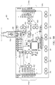
- FIGS. 1A and 1B illustrate a front and back view, respectively, of an adaptive interface device 100 in accordance with some embodiments.
- the adaptive interface device 100 is a programmable device that simulates a computer peripheral device, such as a keyboard or mouse, based on user inputs.
- the user inputs include, for instance, actions that result in completing a conductive circuit loop.
- the user inputs are detected by the adaptive interface device 100, which, in turn, generates outputs that simulate peripheral device outputs.
- the adaptive interface device 100 includes a printed circuit board (PCB) 102 and a connector cable 104 (e.g., a universal serial bus (USB®) cable).
- the PCB 102 includes a microcontroller 106 executing firmware stored on a local memory of the microcontroller 106 or another memory of the PCB 102.
- the PCB 102 includes a port 108 that receives the connector cable 104.
- the opposite end of the connector cable 104 is coupled to a peripheral port 110 of a computer 112 (e.g., a desktop computer, a laptop, or tablet).
- the connector cable 104, port 108, and peripheral port 110 may be, for example, one of a USB®, Firewire®, or Thunderbolt ® port.
- the PCB 102 receives power (e.g., 5 volts direct current (DC)) from the computer 112 via the connector cable 104, which powers components of the PCB 102 including the microcontroller 106.
- the PCB 102 uses the Human Interface Device (HID) protocol to communicate with the computer 112 over the connector cable 104.
- HID Human Interface Device
- the communications signal to the computer 112, for example, particular keyboard (key) presses, mouse clicks, and mouse movements.
- a wireless connection such as a Bluetooth® or Wi-Fi®, is used for communications between the PCB and the computer.
- a portable power supply e.g., a battery may be coupled to the PCB 102 to provide power.
- the PCB 102 includes several input pins that are coupled to the microcontroller 106 (e.g., via traces on the PCB).
- the PCB 102 includes six earth/ground pins 114 provided along the bottom. Additionally, the PCB 102 includes a plurality of input pins, referred to generally as input pins 116, but more particularly identified herein with a letter appended to the identifier 116 (e.g., up arrow pin 116a).
- the front of the PCB 102 includes six input pins 116: the up arrow pin 116a, down arrow pin 116b, left arrow pin 116c, right arrow pin 116d, space pin 116e, and click pin 116f, collectively referred to as input pins 116.
- Each ground pin 114 and input pin 116 includes two conductive apertures, which enable quick connections of alligator clip cables because each half of the alligator clip is received by a respective aperture, and the (spring-loaded) alligator clip clamps onto the bridge portion of the PCB dividing the two apertures.
- conductors without alligator clips may be coupled to the input pins as well, such as via soldering and other techniques.
- the back of the PCB 102 ( FIG. 1B ) has several additional input pins for additional keyboard keys and mouse controls.
- the back of the PCB 102 includes eight additional keyboard inputs 116g for keyboard keys, which are individually labeled W, A, S, D, F, G, H, and J, and six additional input mouse pins 116h for mouse controls, which are graphically labeled with a mouse up, mouse down, mouse left, mouse right, right click, and left click graphic.
- the keyboard input pins 116g and mouse input pins 116h are female headers that may receive paper clip ends, wire ends, jumper ends, or other conductors.
- the back of the PCB 102 also includes an area for using the board to control outputs. Furthermore, as shown in FIGS. 1A and 1B , because the input pins 116 on the front side of the PCB 102 include apertures that extend through the PCB 102, these input pins 116 are also accessible for alligator clip connections from the back side of the PCB 102.
- the particular pin layout and number of pins on the PCB 102 are exemplary.
- the input pins 116 are located on other portions of the PCB 102 and/or in other layout arrangements.
- the PCB 102 includes more or fewer input pins 116 on the front, back, or both.
- Each of the input pins 116 noted above includes a default pin assignment such that each input pin 116 is mapped to particular key board press (e.g., a "w"), mouse control (e.g., a right mouse click), or other HID protocol signal. Labels, graphics, and the layout of the PCB 102 make the default pin assignment apparent to a user. For instance, the up arrow input pin 116a is positioned within an up arrow illustration and space input pin 116e includes the text "space" beneath it (see FIG. 1A ). In some embodiments, different default key presses and mouse controls are assigned to the inputs pins 116. Furthermore, as discussed in detail below, the assignments to the input pins 116 may be reprogrammed such that they map to and simulate different key presses, mouse controls, or other HID protocol signals.
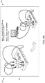
- a ground conductor 120 and an input conductor 122 are coupled to the ground pin 114 and one of the keyboard input pins 116g, respectively.
- the keyboard input pin of FIG. 2 is labeled 116g-w, and represents the keyboard input pin 116g having a default pin assignment of the letter "w" (see uppermost input pin 116 in FIG. 1B ).
- the ground conductor 120 and input conductor 122 are alligator clip cables, which are wires having alligator clips on one or both ends. An insulating wrap may be positioned around the wire, except for the ends that are exposed for conductive coupling.
- the ground conductor 120 and input conductor 122 are coupled at one end to the group pin 114 and keyboard input pin 116g-w, respectively, and, at the opposite end, to a person 124 and an apple 126, respectively. Although removable in some embodiments, like the connector cable 104, the ground conductor 120 and the input conductor 122 may be considered to be part of the adaptive interface device 100.
- a completed circuit loop 128 forms between the keyboard input pin 116g-w and the ground pin 116.
- the loop 128 includes the keyboard input pin 116g-w, the input conductor 122, the apple 126, the person 124, the ground conductor 120, and the ground pin 114.
- the completed circuit loop 128 is detected by the microcontroller 106 of the PCB 102. Completing a circuit loop of one of the input pins 116, which is then detected by the PCB 102, is an example of triggering the input pin 116.
- the PCB 102 sends the computer 112 an HID signal associated with the keyboard input pin 116g-w. That is, the PCB 102 generates an output that simulates a keyboard or mouse action (e.g., key press, mouse click, or mouse movement).
- the computer 112 reacts to receiving the output from the PCB 102 as if the output were sent from a standard keyboard or mouse. Therefore, a user, such as the person 124 in the above-illustrated figure, can simulate a key stroke on a keyboard by touching the apple 126, and the computer 112 will receive the simulated key stroke and react as if the user had pressed the actual key on the key board that is being simulated. For instance, in a word processing program, and where the key stroke simulated is the letter "w,” upon the user touching the apple 126, the word processing program would react as if a user pressed the "w" on the keyboard and display a new "w" on a display of the computer 112.
- the microcontroller 106 monitors the input pins 116 and uses high resistance switching and filtering to provide a sensitive detector that senses a completed circuit loop even through materials like skin, leaves, and modeling compound, which are not highly conductive.
- the PCB 102 uses a pull-up resistor of twenty-two (22) mega ohms.
- Software executing on the microcontroller 106 filters noise on each input pin 116 using a moving window averager to lowpass filter.
- the adaptive interface device could use hardware filtering.
- any material that can conduct electricity will work to complete a circuit loop and be detected by the adaptive interface device 100.
- Other examples of conductive items used to complete a circuit loop between one of the input pins 116 and the ground pins 114 of the PCB 102 include ketchup, pencil graphite, finger paint, lemons, plants, coins, other humans, silverware, water (and wet objects), most foods, cats, dogs, aluminum roil, rain, and many others.
- the input pins 116 are touch-sensitive. In other words, rather than the person 124 touching the apple 126 to trigger the input 116g-w, the user may directly touch the input pin 116g-w to complete the circuit loop.
- the adaptive interface device 100 similarly works with other programs and webpages that take keyboard input, mouse input, and other HID input.
- the adaptive interface device 100 is used with a computer program executing on the computer 112 that generates a virtual piano.
- the virtual piano is played using key presses on a keyboard and/or mouse actions.
- the adaptive interface device 100 generates outputs that are used to play the virtual piano.
- Selected ones of the input pins 116 can be connected to bananas via input conductors (similar to the input conductor 122), the user to ground via a ground conductor (similar to ground conductor 120), and the bananas become the piano keys.
- the adaptive interface device 100 each time a grounded user touches one of the bananas, a circuit loop is completed between the ground pin 114 and one of the input pins 116, which is detected by the adaptive interface device 100. In turn, the adaptive interface device 100 generates an output to the computer 112 that simulates a key press or mouse action, the particular key press or mouse action depending on the particular one of the input pins 116 that is triggered. The output is received by the computer program executing on the computer 112, resulting in playing a key or keys of the virtual piano.
- the adaptive interface device 100 is reprogrammable so that the pin assignments of the input pins 116 can be changed.
- the adaptive interface device 100 can be reprogrammed to change the output signal that is transmitted over the connector cable 104 in response to a particular one of the input pins 116 being triggered. For instance, in the example described with respect to FIG. 2 , triggering the input pin 114g-w causes a "W" HID code to be transmitted to the computer 112.
- the adaptive interface device 100 may be configured so that further triggering of the input pin 114g-w causes an "X" HID code to be transmitted instead of the "W" HDI code.
- the reprogramming also referred to as remapping, is carried out without having to connect the adaptive interface device 100 to a computer having special drivers or specific software installed thereon. Moreover, the reprogramming is carried out without communicating firmware or other updates from a computer to the adaptive interface device 100. Rather, user inputs on the input pins 116 of the adaptive interface device 100 itself cause reprogramming of the adaptive interface device 100.
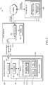
- FIG. 3 illustrates a block diagram of reprogramming system 150 including the adaptive interface device 100, a local computer 154, and a remote server 156.
- the local computer 154 is a computing device and may be, for example, a laptop, tablet, or desktop computer, such as the computer 112 shown in FIG. 2 .
- the adaptive interface device 100 includes a processor 160, a memory 162, the input pins 116 (also referred to as programmable inputs), and the port 108.
- the processor 160 and memory 162 form part of the microcontroller 106 (shown in FIG. 1B ) and the programmable inputs include the input pins 116 (shown in FIGS. 1A and 1B ).
- the memory 162 includes instructions executed by the processor 160, as well as data used by the processor 160, to carry out the functionality of the adaptive interface device 100 described herein.
- the instructions include reprogramming code 170 executed by the processor 160 in a remapping mode, as well as other firmware 172, which includes at least code for a normal operation mode of the adaptive interface device.
- the reprogramming code 170 defines navigable data structure 174 that are navigable by the user during reprogramming and controls the reprogramming of the input pins 116 in accordance with the user's navigation.
- the memory 162 further includes a key mapping 180, which defines the correlation between (a) the input pins 116 of the adaptive interface device 152 that can be triggered by a user and (b) the correlating output codes that the adaptive interface device 152 is to generate in response to being triggered.
- a key mapping 180 defines the correlation between (a) the input pins 116 of the adaptive interface device 152 that can be triggered by a user and (b) the correlating output codes that the adaptive interface device 152 is to generate in response to being triggered.
- the processor 160 may access the memory 162 and use an identifier of the actuated input pin 116 as an index into a data table of the key mapping 180.
- the data table also referred to as a key mapping index, associates the identifier with an HID output code, which is provided back to the processor 160.
- the processor 160 then outputs the returned HID output code on the port 108.
- the key mapping 180 may include a current key mapping defining the current input pin-to-output code assignments, as well as a default key mapping that may be used to overwrite the current key mapping upon a reset or restore operation of the adaptive interface device 100.
- a portion of the key mapping 180 is overwritten or otherwise updated to change the stored input pin-to-output code assignments. In other words, some or all of the input pins 116 are remapped to different output codes.
- the local computer 154 is coupled to the remote server 156 via the Internet, which may include one or more wired and/or wireless connections.
- the local computer 154 and remote server 156 each include a processor and memory.
- the local computer 154 includes a web browser software application (web browser) 182 executed by the processor (not shown), a user interface including a display 184, and other user inputs (not shown), such as a keyboard and mouse, for interacting with the web browser 182.
- the user is operable to enter an address into or otherwise navigate the web browser 182 to a web site for adaptive interface device reprogramming on the remote server 156, which causes the remote server to transmit web pages including java application software (web page software) 186 to the web browser 182.
- the web browser 182 interprets and/or executes the web page software 186, and provides corresponding visual output to the display 184, which, as discussed in further detail below, assists in reprogramming the adaptive interface device 100.
- the local computer 154 and remote server 156 are coupled by a network connection not including the Internet, such as a local network or intranet connection.
- the web page software 186 is stored on the local computer 154 so that an Internet connection (or other connection) to the remote server 156 is not used during reprogramming of the adaptive interface device.
- a user navigates the navigable data structure 174 within the microcontroller 106 of the adaptive interface device 100 through certain specified combinations of user inputs using the input pins 116.
- the adaptive interface device 100 as illustrated in FIGS. 1A and 1B does not itself have a display or simple means to provide visual feedback of a user's reprogramming of the adaptive interface device. However, as described above, the adaptive interface device 100 is able to output signals to the computer 154 to provide visual and/or audible feedback to a user to assist in programming.
- the processor 160 outputs signals representing the navigation inputs received via the input pins 116 and generates outputs representing the navigation inputs over the connector cable 104.
- the web page software 186 is executing on the web browser 182 of the coupled local computer 154, which is operable to receive the outputs from the adaptive interface device 100 and provide the user with a graphical representation on the display 184 of the navigable data structure 174 used to reprogram that the user is navigating.
- the web browser 182 executing on the local computer 154 includes a corresponding copy of the navigable data structure 174 received from the web page software 186, referred to as a replica data structure 188.
- the web page software 186 may include several replica data structures 188, one for each type of adaptive interface device 100.
- the web browser 182 receives the outputs from the adaptive interface device 100 and navigates the replica data structure 188 accordingly, providing real-time visual feedback of the user's navigation.
- This browser-based graphical user interface provides the user otherwise unavailable visual feedback and allows the user to more easily navigate an otherwise complex array of data structures within the adaptive interface device 100.
- the communication between the adaptive interface device 100 and local computer 154 is one-way, from the adaptive interface device 100 to the local computer 154, i.e., to the web browser 182. As the communication is one-way, the local computer 154 does not communicate back to the adaptive interface device 100, at least not substantively. In some instances, certain acknowledgement and handshaking communications are sent from the local computer 154 to the adaptive interface device 100 to establish or maintain a communication link according to certain communication protocols. In these instances, the communication between the computer 154 and the adaptive interface device may still be considered one-way because substantive data payloads are not passed from the local computer 154 to the adaptive interface device 100.
- one-way communication means that substantive data payloads are transmitted via a communication link in only one direction (e.g., from device A to B, and not from device B to A), rather than in two directions (e.g., from device A to B, and also from device B to A).
- programming data and commands that update the key mapping 180 e.g., particular pin assignment values, save commands, and restore commands
- the programming data and commands are generated from within the adaptive interface device 100 by the reprogramming code 170 in response to navigation input received by the input pins 116.
- the programming data and commands are examples of substantive data payloads, while mere acknowledgement and handshaking communications to establish or maintain a communication link according to certain communication protocols are nonsubstantive.
- the web browser 182 is an application on the local computer 154 that is in the foreground to ensure that it receives the communication from the adaptive interface device 100. If the user navigates to another application or webpage, causing the web browser 182 to be in the background, and then the user triggers one of the input pins 116 of the adaptive interface device 100, the web browser 182 may not receive the user input. Therefore, synchronization between the actual navigation of the navigable data structure 174 on the adaptive interface device 100 and the replica data structure 188 on the web browser 182 may be lost. Thus, visual feedback of the user's actual navigation on the adaptive interface device 100 from that point forward may be inaccurate.
- a user couples a five volt (5 volt) DC power supply to the PCB 102, rather than connecting it to the local computer 154 via the connector cable 104, and programs the adaptive interface device 100 without visual feedback from the local computer 154.
- the adaptive interface device 100 is but an example of the interface devices that may be programmed as described herein.
- Other interface devices may use other techniques for receiving user inputs and triggering inputs that result in outputs of the interface device. Such other techniques may include one or more of pushbuttons, keypads, optical sensors, and capacitive sensors interfacing with a microcontroller.
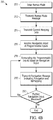
- FIGS. 4A and 4B illustrate methods 200 and 210, respectively, for programming an adaptive interface device.
- the methods 200 and 210 are described with respect to reprogramming the adaptive interface device 100; however, in some embodiments, the methods are used to reprogram other interface devices.
- the method 200 is generally described from the perspective of a computing device that is coupled to an adaptive interface device being reprogrammed, while method 210 is generally described from the perspective of an adaptive interface device being reprogrammed. Together, the methods 200 and 210 may be carried out by components of a reprogramming system, such as reprogramming system 150, to reprogram an adaptive interface device.
- a reprogramming system such as reprogramming system 150
- a remapping graphical user interface (remapping GUI) 221 is provided on the display 184 of the local computer 154.
- the remapping GUI 221 may be provided by the web browser 182 based on the web page software 186 obtained from the remote server 156, as described above, or based on a local software application residing on the local computer 154.
- the remapping GUI 221 includes various screens to convey information to a user, examples of which are shown and described with respect to FIGS. 5A-5E .
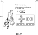
- a user starts the web browser 182 on the local computer 154, which is connected to the Internet, and navigates to the reprogramming web page having the web page software 186.
- the web browser 182 displays a remapping start screen 222 illustrated in FIG. 5A .
- this screen 222 instructs the user to disconnect their adaptive interface device 100 and to then initiate the process by clicking a start button 224 (e.g., using a mouse coupled to the local computer 154). This clicking action ensures that the web browser 182 is in the foreground on the local computer 154 and will be receiving data from the adaptive interface device 100 in later stages.
- the remapping GUI 221 is updated to display the enter remap mode screen 226 ( FIG. 5B ).
- the screen 226 instructs the user how to boot the adaptive interface device 100 in the remap mode.
- the user is instructed to connect the input pin 116a and 116b (e.g., with a first alligator clip cable), to connect the input pin 116c and 116d (e.g., with a second alligator clip cable), and then to connect the adaptive interface device 100 to the computer 154 using the connector cable 104.
- LEDs light emitting diodes
- the local computer 154 receives a remap mode message from the adaptive interface device 100 (step 228).
- the adaptive interface device 100 outputs a confirmation string upon entering the remap mode, the string including a name of the adaptive interface device 100, the software version, and the hardware version (e.g., "mm v1.20ab").
- the web browser 182 can determine from the confirmation string the software and hardware version of the coupled adaptive interface device 100. Accordingly, when the adaptive interface device 100 is revised or an alternate version is coupled that may have different layouts, inputs, and capabilities, the web browser 182 can proceed appropriately (e.g., obtain the appropriate replica data structure 188).
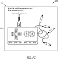
- the web browser 182 advances the remapping GUI 221 to a confirmation screen 230 of FIG. 5C .
- the confirmation screen 230 instructs the user to disconnect the alligator clips.
- the adaptive interface device 100 detects that the alligator clips are disconnected, the adaptive interface device 100 sends current mapping data to the web browser 182 (step 232).
- the current mapping data may include a fifty-seven character configuration string to the web browser 182 that identifies the current programed mapping of the adaptive interface device 100 (i.e., the key mapping 180), such as "suph50h52h51h4fh2chf0h1ah04h16h07h09h0ahf4hf5hf2hf3hf0hf1," plus three additional characters (e.g., "h50”) indicating the position that the user is located at within the navigable data structure 174.
- the key mapping 180 such as "suph50h52h51h4fh2chf0h1ah04h16h07h09h0ahf4hf5hf2hf3hf0hf1," plus three additional characters (e.g., "h50") indicating the position that the user is located at within the navigable data structure 174.
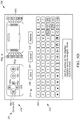
- the web browser 182 advances the remapping GUI 221 to a remapping screen 236, as illustrated on FIG. 5D (in step 234).
- the remapping screen 236 includes display of a graphical representation of the navigable data structure 174.
- the graphical representation of the navigable data structure 174 includes a graphic representation of the adaptive interface device 100 and its input pins 116 (virtual adaptive interface 240), an onscreen keyboard (OSK) 242 (also referred to as a virtual keyboard 242), and virtual programming control buttons 244.
- OSK onscreen keyboard
- the virtual adaptive interface 240 that is shown is based on the version information transmitted as part of the remap mode message in step 228. In other words, the particular shape, layout, and programmable inputs illustrated are based on the version information. Additionally, the virtual adaptive interface 240 is shown with the current mapping of the input pins 116 provided with the current mapping data in step 232. Accordingly, the virtual adaptive interface 240 is a visual representation of the front and back sides of the adaptive interface device 100 with current mappings for each of the input pins 116.
- the virtual programming control buttons 244 include a row having a save button 246, a cancel button 247, and a restore button 248, which are described in further detail below.
- Navigation of the remapping screen 236 is performed by way of user inputs on the adaptive interface device 100, which are interpreted and conveyed as navigation codes over the one-way communication to the local computer 154.
- the user may navigate the remapping screen 236 by causing actuation of (triggering) the up arrow input pin 116a, down arrow input pin 116b, left arrow input pin 116c, and right arrow input pin 116d, and the click input pin 116f on the adaptive interface device 100.
- navigating the remapping screen 236 through triggering these input pins 116 visualizes the actual navigation of data structure 174 on the adaptive interface device 100 that is occurring through the same triggering.
- Triggering one of these input pins 116 generates a navigation control code that is sent to the web browser 182 over the connector cable 104.
- the navigation control code is a three character hex code starting with an "x" value. More specifically, the navigation controls codes are set forth in TABLE I as follows: TABLE I Navigation Control Codes (X__) Up X52 Right X4F Down X51 Click XF0 Left X50
- a cursor 250 is provided on the remapping screen 236.
- the cursor 250 may be a contrasting color, flashing element, or, as illustrated, a circle, that highlights a current position of the user within the navigable data structure 174.
- the adaptive interface device 100 receives various navigation inputs from the user triggering input pins 116 and, in response to each navigation input, the adaptive interface device 100 outputs a navigation code to the web browser 182 of the local computer 154 (step 252).
- the web browser 182 updates the remapping screen 236 in accordance with the received navigation codes (step 254).
- the updates are, for instance, changing the location of the cursor 250 on the remapping screen 236.
- the web browser 182 determines whether the most recent navigation code indicates that the adaptive interface device 100 has been remapped (e.g., the save button 246 has been selected). If the adaptive interface device 100 has not been remapped, the method 200 returns to step 252. Steps 252 and 254 may be repeated as a user navigates the navigable data structure 174 and step 256 continues to be evaluated to be false.
- the right arrow navigation codes cause the cursor 250 to proceed through the input pins 116 in the following order: left arrow, up arrow, down arrow, right arrow, space, click, W, A, S, D, F, G, mouse up, mouse down, mouse left, mouse right, mouse left click, mouse right click, and then, looping back, the left arrow again.
- Triggering the down arrow input pin 114b on the adaptive interface device 100 will drop the cursor off of the virtual adaptive interface 240 and to the virtual programming control buttons 244, where the user can select the save button 246, cancel button 247, or restore button 248. Triggering the up arrow input pin 114a on the adaptive interface device 100 brings the cursor 250 back up to the virtual adaptive interface 240.
- Navigation to the virtual keyboard 242 is performed by triggering the click input pin 116f on the adaptive interface device 100 when the cursor 250 is on one of the (virtual) input pins 116 of the virtual adaptive interface 240. Selecting one of the (virtual) input pins 116 and navigating to the virtual keyboard 242 allows the user to modify the key/control assigned to the selected one of the input pins 116 of the adaptive interface device 100.
- the click input pin 116f when the cursor 250 is on one of the virtual input pins 116, the cursor 250 jumps to the location of the currently assigned key on the virtual keyboard 242.
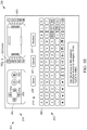
- FIG. 5E illustrates the remapping screen 236 after the input pin 116g-w on the virtual adaptive interface 240 is updated from a "W" to an "X" character.
- the actual key mapping 180 of the adaptive interface device 100 is not yet updated. Rather, to update the key mapping 180 with the modified key mapping displayed on the virtual interface device 240, a user positions the cursor 250 on the save button 246 and triggers the click input pin 116f. Upon triggering the click input pin 116f when the cursor 250 is positioned on the save button 246, the adaptive interface device 100 is remapped. This remapping is detected in step 256 by the web browser 182 based on the navigation inputs, including the triggering of the click input pin 116f when the cursor 250 was positioned on the save button 246.
- the web browser 182 displays the updated key mapping 180 of the adaptive interface device 100 on the virtual adaptive interface 240.
- the virtual adaptive interface 240 will already be showing the updated key mapping upon selection of the save button 246 and, in step 258, the virtual interface device 240 is unchanged.
- an additional visual indicator e.g., flash, color change, or particular text
- step 260 the web browser 182 determines whether additional navigation input is received. If additional navigation codes are received by the web browser 182, the method returns to step 254 to update the remapping screen 236. If no additional navigation codes are received, e.g., for a predetermined amount of time, the method 200 ends. The method 200 may also be exited through selection of the cancel button 247.
- selecting the save button 246 does not cause the updated mapping to be sent from the computer 154 to the adaptive interface device 100. Rather, the various navigation inputs provided by the user in the steps i., ii., and iii. to the adaptive interface device 100 are received by the reprogramming code 170 and, when the save button 246 is selected in step v., the reprogramming code 170 updates the key mapping 180 according to the received user inputs.
- the cancel button 247 when selected by the user, is used to cause the adaptive interface device 100 to exit the remapping mode and return to the normal operating mode. Upon returning to the normal operating mode, the key mapping 180 will have the values assigned in the most recent save operation.
- the key mapping 180 is overwritten with default key assignments.
- the method 210 begins with the adaptive interface device 100 receiving inputs that cause entry into the remapping mode (step 270). More particularly, as described above with respect to FIG. 5B , a user may connect particular input pins 116 together and then connect the adaptive interface device 100 to the local computer 154 via the connector cable 104 to provide power thereto. Upon providing power to the adaptive interface device 100, the particular connections are detected by the microcontroller 106, and the adaptive interface device 100 enters into the remapping mode.
- the adaptive interface device 100 After the adaptive interface device 100 enters the remapping mode, the adaptive interface device 100 transmits the remap mode message to the local computer 154 (step 272).
- the remap mode message is transmitted in step 272 as it was described with respect to step 228 of FIG. 4A .
- the adaptive interface device 100 upon detecting that the particular connections of the input pins 116 used to enter the remapping mode have been broken, the adaptive interface device 100 transmits the current mapping data to the local computer 154, as it was described above with respect to step 232 of FIG. 4A .
- step 276 the adaptive interface device 100 receives navigation input at the input pins 116.
- the user triggers various input pins 116 by selectively connecting the input pins 116 to ground.
- step 278 the navigable data structure 178 is navigated and the adaptive interface device 100 is remapped.
- the navigation inputs cause the navigation of navigable data structure 174, which leads the reprogramming code 170 to update the key mapping 180, as described in greater detail above.
- step 280 the adaptive interface device 100 transmits navigation codes to the web browser 182 of the local computer 154 indicative of the navigation input received.
- the web browser 182 updates the remapping screen 236 (see FIG. 5D ).
- the steps 276, 278, and 280 are repeatedly cycled between and overlap in execution during the process of remapping the programmable inputs of the adaptive interface device 100.
- a navigation code is transmitted in step 280, and the transmissions of step 280 occur in real time as navigation inputs are received in step 276.
- step 280 This overlapping execution of steps 276, 278, and 280 contrasts with sequentially carrying out step 276, 278, and then step 280 by waiting for step 276 to be complete before proceeding to step 278 and waiting for step 278 to be complete before proceeding to step 280.
- the navigation codes transmitted in step 280 are used to update the remapping screen 236 as described above with respect to method 200 of FIG. 4A .
- step 282 if further navigation input is received by the adaptive interface device 100, the method returns to step 278. If no additional navigation codes are received in step 282, e.g., for a predetermined amount of time, the method 210 ends. The method 210 may also be exited through selection of the cancel button 247.
- the adaptive interface device 100 and the remapping screen 236 of the web browser 182 are semi-independent state machines.
- the state of the remapping screen 236 is controlled by the adaptive interface device 100, but the adaptive interface device 100 is not controlled by the remapping screen 236 and does not receive data from the remapping screen 236 to confirm that the state machines are in synchronization. Therefore, in addition to the navigation control codes (L, R, U, D, Click), the adaptive interface device 100 sends a navigation state code (i.e., the expected location of the cursor 250) with each input pin 116 actuation.
- a navigation state code i.e., the expected location of the cursor 250
- Each navigation state code is a three-character hex code as well, but the navigation state codes start with an "h” while the navigation control codes start with an "x.” For instance, the up arrow navigation state code is represented by "h52,” while the up arrow navigation control code is represented by an "x52.”
- a list of navigation state codes is provided below in Table II. TABLE II Navigation State Codes (H__) Letters: A (H04) to Z (H1D) Backspace H2A Numbers: 1 (H1E) to 0 (H27) Esc H29 Space H2C Up H52 Enter H28 Down H51 Tab H2B Left H50 , H36 Right H4F .
- the cursor 250 starts at the left arrow on the virtual adaptive interface 240 based on the coding of TABLE II above.
- the string “x4fh52” is sent as the navigation code, which includes the navigation control code “x4f' and the navigation state code "h52.”
- This navigation code indicates to the web browser 182 that (1) the cursor 250 is to be shifted to the right one increment based on the navigation control code "x4f' and (2) that the expected location of the cursor 250 after the shift is the up arrow based on the navigation state code "h52.”
- Pressing the right arrow again causes the adaptive interface device to output the string "x4fh51” as the navigation code, which indicates to advance the cursor 250 one increment right (“x4f') and confirms that the cursor 250 will then be located at the down arrow ("h51").
- the remapping GUI 221 and web browser 182 is set such that computer inputs via other typical peripherals (e.g., keyboard or mouse) do not effect or navigate the remapping screen 236. This technique assists in allowing the remapping screen 236 to stay synchronized with the internal state of the adaptive interface device 100.
- the navigation control codes that the adaptive interface device 100 outputs are non-standard hex strings, instead of the standard HID equivalent. For instance, while in a normal operation mode, the user may trigger the right arrow input pin 116d on the adaptive interface device 100 to output an HID equivalent that navigates right on the display 184 of the local computer 154, when in remapping mode, the right arrow on the adaptive interface device 100 actually outputs "x4f' (along with the three character hex code representing the expected state), which are not standard HID codes. Thus, if the user pressed the right arrow on a keyboard connected to the local computer 154, the remapping screen 236 would not recognize the input.
- the web browser will display a time out message.
- the time out message may indicate that communication has timed out and request that the user refresh the page to start over (e.g., at the screen 222 of FIG. 5A ).
- the adaptive interface device 100 may also be setup to exit the remapping mode if it fails to receive a user input for the predetermined amount of time while in the remapping mode. If such an automatic exit occurs because of a time out period being reached, the adaptive interface device 100 may resort back to default programming of its input pins 116, or may resort back to the most recently saved programming of its input pins 116.
- the embodiments of the adaptive interface device 100 described above are examples of devices that are reprogrammable using the above-noted techniques.
- the reprogramming techniques are used to reprogram, for example, other programmable computer interface devices and/or other programmable devices that do not generally serve as a computer interface device.
- a programmable device that is not generally a computer interface device may include a PCB with a microcontroller mounted thereon and various inputs and outputs (e.g., pins, LEDs, sensors, vibration generators, and/or speakers) usable for various functions that, during typical operation, are independent of interfacing with a computer.
- the programmable device is coupled to a computer, e.g., using a USB cable, and the computer then provides real time visual feedback of the user's reprogramming based on one-way communication using similar techniques as described above.
- the reprogramming may be used to alter settings of the microcontroller, alter input or output parameters, remap inputs and/or outputs to be assigned to different values or functions, restore default settings, or customize other programmable aspects of the device.
- the invention provides, among other things, an adaptive interface device that is programmable and a method of programming an adaptive interface device.
- an adaptive interface device that is programmable and a method of programming an adaptive interface device.
Landscapes
- Engineering & Computer Science (AREA)
- General Engineering & Computer Science (AREA)
- Theoretical Computer Science (AREA)
- Human Computer Interaction (AREA)
- Physics & Mathematics (AREA)
- General Physics & Mathematics (AREA)
- Multimedia (AREA)
- User Interface Of Digital Computer (AREA)
Claims (15)
- Verfahren (200) zum Programmieren einer anpassbaren Schnittstellenvorrichtung (100) mit programmierbaren Eingängen (116), wobei das Verfahren umfasst:Bereitstellen (220) einer grafischen Neuzuordnungsbenutzerschnittstelle auf einem Anzeigebildschirm einer Computervorrichtung (154), der mit der anpassbaren Schnittstellenvorrichtung verbunden ist;Bereitstellen (234), auf der grafischen Neuzuordnungsbenutzerschnittstelle, einer grafischen Darstellung einer navigierbaren Datenstruktur (174) der anpassbaren Schnittstellenvorrichtung, die in der anpassbaren Schnittstellenvorrichtung zur Neuzuordnung der programmierbaren Eingänge der anpassbaren Schnittstellenvorrichtung verwendet wird;Empfangen (252), von der anpassbaren Schnittstellenvorrichtung, von Navigationscodes, die Navigationseingaben anzeigen, welche an der anpassbaren Schnittstellenvorrichtung empfangen wurden, und die zum Navigieren der realisierbaren Datenstruktur dienen und die Neuzuordnung anzeigen;Aktualisieren (254), der grafischen Darstellung basierend auf den Navigationscodes, dadurch Bereitstellen von visuellem Feedback für einen Benutzer der anpassbaren Schnittstellenvorrichtung während der Programmierung der anpassbaren Schnittstellenvorrichtung;Bestimmen (256), basierend auf den Navigationscodes, dass mindestens einer der programmierbaren Eingänge der anpassbaren Schnittstellenvorrichtung durch die anpassbare Schnittstellenvorrichtung neu zugeordnet wurde, um eine aktualisierte Zuordnung zu haben; undAnzeigen (258), auf der grafischen Neuzuordnungsbenutzerschnittstelle, der aktualisierten Zuordnung der anpassbaren Schnittstellenvorrichtung.
- Verfahren nach Anspruch 1, wobei die Computervorrichtung mit der anpassbaren Schnittstellenvorrichtung über ein Datenkabel (104) verbunden ist, und
wobei die Navigationscodes über das Datenkabel empfangen werden. - Verfahren nach Anspruch 1 oder 2, des Weiteren umfassend:Empfangen, von der anpassbaren Schnittstellenvorrichtung, von aktuellen Zuordnungsdaten; undAnzeigen, auf der grafischen Neuzuordnungsbenutzerschnittstelle, einer aktuellen Zuordnung der anpassbaren Schnittstellenvorrichtung basierend auf den aktuellen Zuordnungsdaten.
- Verfahren nach einem der Ansprüche 1 bis 3, des Weiteren umfassend:Anzeigen, auf der grafischen Neuzuordnungsbenutzerschnittstelle, einer virtuellen anpassbaren Schnittstellenvorrichtung, einschließlich der programmierbaren Eingänge der anpassbaren Schnittstellenvorrichtung; undwobei das Anzeigen der aktualisierten Zuordnung der anpassbaren Schnittstellenvorrichtung das Anzeigen der aktualisierten Zuordnung auf der virtuellen anpassbaren Schnittstellenvorrichtung beinhaltet.
- Verfahren nach einem der Ansprüche 1 bis 4, wobei die grafische Darstellung der navigierbaren Datenstruktur eine virtuelle Tastatur ist.
- Verfahren (210) zum Programmieren einer anpassbaren Schnittstellenvorrichtung (100), wobei das Verfahren umfasst:Senden (272), durch die anpassbare Schnittstellenvorrichtung, einer Neuzuordnungsmodusnachricht an eine Computervorrichtung (154), die mit der anpassbaren Schnittstellenvorrichtung verbunden ist, wobei die Neuzuordnungsmodusnachricht anzeigt, dass die anpassbare Schnittstellenvorrichtung in einen Neuzuordnungsmodus eingetreten ist;Empfangen (276), durch die anpassbare Schnittstellenvorrichtung, einer Navigationseingabe, welche eine navigierbare Datenstruktur (174) der anpassbaren Schnittstellenvorrichtung navigiert, die zur Neuzuordnung von programmierbaren Eingängen (116) der anpassbaren Schnittstellenvorrichtung verwendet wird;Neuzuordnen (278), durch die anpassbare Schnittstellenvorrichtung, der programmierbaren Eingänge basierend auf der Navigationseingabe; undSenden (280), durch die anpassbare Schnittstellenvorrichtung, von Navigationscodes, welche die empfangene Navigationseingabe anzeigen und die Neuzuordnung anzeigen, wobei die Navigationscodes an die Computervorrichtung gesendet werden, die dazu konfiguriert ist, visuelles Feedback für einen Benutzer der anpassbaren Schnittstellenvorrichtung während der Programmierung der anpassbaren Schnittstellenvorrichtung basierend auf den Navigationscodes bereitzustellen.
- Verfahren nach Anspruch 6, des Weiteren umfassend:
beim Eintritt in den Neuzuordnungsmodus, Senden von aktuellen Neuzuordnungsdaten an die Computervorrichtung, wobei die aktuellen Neuzuordnungsdaten eine aktuelle Neuzuordnung der programmierbaren Eingänge der anpassbaren Schnittstellenvorrichtung anzeigen. - Verfahren nach Anspruch 6 oder 7, des Weiteren umfassend:
Empfangen einer Aufforderung über die programmierbaren Eingänge, die anpassbare Schnittstellenvorrichtung in den Neuzuordnungsmodus zu versetzen. - Verfahren nach Anspruch 8, des Weiteren umfassend:vor dem Empfangen der Aufforderung zum Eintritt in den Neuzuordnungsmodus, Empfangen einer Benutzereingabe an einem ersten programmierbaren Eingang der programmierbaren Eingänge;Senden, durch die anpassbare Schnittstellenvorrichtung, eines ersten Codes an die Computervorrichtung, der einen ersten zugeordneten Ausgang repräsentiert, in Reaktion auf die Benutzereingabe;Empfangen einer weiteren Benutzereingabe an dem ersten programmierbaren Eingang nach der Neuzuordnung; undSenden, durch die anpassbare Schnittstellenvorrichtung, eines zweitem Codes an die Computervorrichtung, der einen zweiten zugeordneten Ausgang repräsentiert, in Reaktion auf die weitere Benutzereingabe.
- Anpassbare Schnittstellenvorrichtung (100), die programmierbar ist, wobei die anpassbare Schnittstellenvorrichtung umfasst:programmierbare Eingänge (116);eine Eingabe-/Ausgabeschnittstelle (108), die dazu konfiguriert ist, mit einer Computervorrichtung (154) verbunden zu werden;einen Speicher (162), der eine navigierbare Datenstruktur (174) und einen Schlüsselzuordnungsindex enthält; undeinen Prozessor (160), der zu Folgendem konfiguriert ist:Senden (172) einer Neuzuordnungsmodusnachricht über die Eingabe-/Ausgabeschnittstelle an die Computervorrichtung, wobei die Neuzuordnungsmodusnachricht anzeigt, dass die anpassbare Schnittstellenvorrichtung in einen Neuzuordnungsmodus eingetreten ist;Empfangen (276), über die programmierbaren Eingänge, einer Navigationseingabe, welche die navigierbare Datenstruktur navigiert;Neuzuordnen (278) der programmierbaren Eingänge basierend auf der Navigationseingabe; undSenden (280), über die Eingabe-/Ausgabeschnittstelle an die Computervorrichtung, von Navigationscodes, welche die empfangene Navigationseingabe anzeigen und die Neuzuordnung anzeigen, wobei die Navigationscodes an die Computervorrichtung gesendet werden, die dazu konfiguriert ist, visuelles Feedback für einen Benutzer der anpassbaren Schnittstellenvorrichtung während der Programmierung der anpassbaren Schnittstellenvorrichtung basierend auf den Navigationscodes bereitzustellen.
- Programmierbare anpassbare Schnittstellenvorrichtung nach Anspruch 10, des Weiteren umfassend:
ein Datenkabel (104), das mit der Eingabe-/Ausgabeschnittstelle und der Computervorrichtung verbunden ist, um eine Kommunikationsverbindung zu bilden. - Programmierbare anpassbare Schnittstellenvorrichtung nach Anspruch 10 oder 11, wobei der Schlüsselzuordnungsindex eine Beziehung zwischen den einzelnen programmierbaren Eingängen und einem entsprechenden Ausgangscode herstellt.
- Programmierbare anpassbare Schnittstellenvorrichtung nach einem der Ansprüche 10 bis 12, wobei der Schlüsselzuordnungsindex beim Eintritt in den Neuzuordnungsmodus aktuelle Zuordnungsdaten aufweist, die eine aktuelle Zuordnung der programmierbaren Eingänge der anpassbaren Schnittstellenvorrichtung anzeigen; und
wobei der Schlüsselzuordnungsindex bei Abschluss der Neuzuordnung aktualisierte Zuordnungsdaten aufweist, die eine aktualisierte Zuordnung der programmierbaren Eingänge der anpassbaren Schnittstellenvorrichtung anzeigen. - Programmierbare anpassbare Schnittstellenvorrichtung nach einem der Ansprüche 10 bis 13, wobei der Prozessor des Weiteren zu Folgendem konfiguriert ist:Empfangen, vor der Neuzuordnung, einer Benutzereingabe an einem ersten programmierbaren Eingang der programmierbaren Eingänge;Senden eines ersten Codes an die Computervorrichtung, der einen ersten zugeordneten Ausgang repräsentiert, in Reaktion auf die Benutzereingabe;Empfangen einer weiteren Benutzereingabe über den ersten programmierbaren Eingang nach der Neuzuordnung; undSenden eines zweiten Codes an die Computervorrichtung, der einen zweiten zugeordneten Ausgang repräsentiert, in Reaktion auf die weitere Benutzereingabe.
- Programmierbare anpassbare Schnittstellenvorrichtung nach einem der Ansprüche 10 bis 14, des Weiteren umfassend:einen Leiter, der selektiv an zwei der programmierbaren Eingänge gesichert wird, um einen leitenden Pfad zwischen den zwei programmierbaren Eingängen zu bilden, und wobeider Prozessor des Weiteren dazu konfiguriert ist, den leitenden Pfad zu ermitteln, der von dem Leiter gebildet wird, und in Reaktion darauf die anpassbare Schnittstellenvorrichtung in den Neuzuordnungsmodus zu versetzen.
Applications Claiming Priority (2)
| Application Number | Priority Date | Filing Date | Title |
|---|---|---|---|
| US201462047618P | 2014-09-08 | 2014-09-08 | |
| PCT/US2015/049020 WO2016040375A1 (en) | 2014-09-08 | 2015-09-08 | An adaptive interface device that is programmable and a system and method of programming an adaptive interface device |
Publications (3)
| Publication Number | Publication Date |
|---|---|
| EP3191925A1 EP3191925A1 (de) | 2017-07-19 |
| EP3191925A4 EP3191925A4 (de) | 2018-04-11 |
| EP3191925B1 true EP3191925B1 (de) | 2020-01-01 |
Family
ID=55437495
Family Applications (1)
| Application Number | Title | Priority Date | Filing Date |
|---|---|---|---|
| EP15840129.9A Active EP3191925B1 (de) | 2014-09-08 | 2015-09-08 | Programmierbare anpassbare schnittstellenvorrichtung und verfahren zur programmierung einer anpassbaren schnittstellenvorrichtung |
Country Status (4)
| Country | Link |
|---|---|
| US (1) | US9886099B2 (de) |
| EP (1) | EP3191925B1 (de) |
| CN (1) | CN107003745A (de) |
| WO (1) | WO2016040375A1 (de) |
Families Citing this family (5)
| Publication number | Priority date | Publication date | Assignee | Title |
|---|---|---|---|---|
| EP3191925B1 (de) | 2014-09-08 | 2020-01-01 | Joylabz LLC | Programmierbare anpassbare schnittstellenvorrichtung und verfahren zur programmierung einer anpassbaren schnittstellenvorrichtung |
| US20160204559A1 (en) * | 2015-01-11 | 2016-07-14 | Robert Baschnagel | Flexible Twisted Cable With End Connectors |
| EP3104671B1 (de) | 2015-05-08 | 2018-07-18 | Joylabz LLC | Verfahren und systeme zur magnetkupplung |
| CN110192242B (zh) * | 2017-01-20 | 2021-11-30 | 森兰信息科技(上海)有限公司 | 用于钢琴系统的琴键辅助用户输入系统和方法 |
| US11457260B2 (en) | 2021-01-15 | 2022-09-27 | Universal Electronics Inc. | Systems and methods for controlling device configuration in a networked environment |
Family Cites Families (10)
| Publication number | Priority date | Publication date | Assignee | Title |
|---|---|---|---|---|
| US6071194A (en) * | 1997-06-19 | 2000-06-06 | Act Labs Ltd | Reconfigurable video game controller |
| US7154480B2 (en) * | 2002-04-30 | 2006-12-26 | Kazuho Iesaka | Computer keyboard and cursor control system with keyboard map switching system |
| US7782306B2 (en) * | 2003-05-09 | 2010-08-24 | Microsoft Corporation | Input device and method of configuring the input device |
| US20060132447A1 (en) * | 2004-12-16 | 2006-06-22 | Conrad Richard H | Method and apparatus for automatically transforming functions of computer keyboard keys and pointing devices by detection of hand location |
| GB0801626D0 (en) * | 2008-01-30 | 2008-03-05 | Lancaster University | Adaptive keyboard |
| US20100265182A1 (en) * | 2009-04-20 | 2010-10-21 | Microsoft Corporation | Context-based state change for an adaptive input device |
| WO2010126495A1 (en) * | 2009-04-29 | 2010-11-04 | Hewlett-Packard Development Company, L.P. | Controlling a keyboard |
| US20100281268A1 (en) * | 2009-04-30 | 2010-11-04 | Microsoft Corporation | Personalizing an Adaptive Input Device |
| US8836643B2 (en) * | 2010-06-10 | 2014-09-16 | Qualcomm Incorporated | Auto-morphing adaptive user interface device and methods |
| EP3191925B1 (de) | 2014-09-08 | 2020-01-01 | Joylabz LLC | Programmierbare anpassbare schnittstellenvorrichtung und verfahren zur programmierung einer anpassbaren schnittstellenvorrichtung |
-
2015
- 2015-09-08 EP EP15840129.9A patent/EP3191925B1/de active Active
- 2015-09-08 CN CN201580047295.0A patent/CN107003745A/zh active Pending
- 2015-09-08 US US14/848,170 patent/US9886099B2/en active Active
- 2015-09-08 WO PCT/US2015/049020 patent/WO2016040375A1/en not_active Ceased
Non-Patent Citations (1)
| Title |
|---|
| None * |
Also Published As
| Publication number | Publication date |
|---|---|
| EP3191925A4 (de) | 2018-04-11 |
| CN107003745A (zh) | 2017-08-01 |
| US9886099B2 (en) | 2018-02-06 |
| EP3191925A1 (de) | 2017-07-19 |
| US20160070362A1 (en) | 2016-03-10 |
| WO2016040375A1 (en) | 2016-03-17 |
Similar Documents
| Publication | Publication Date | Title |
|---|---|---|
| EP3191925B1 (de) | Programmierbare anpassbare schnittstellenvorrichtung und verfahren zur programmierung einer anpassbaren schnittstellenvorrichtung | |
| KR100700143B1 (ko) | 터치 키패드의 키선택 표시 장치 및 그 방법 | |
| KR100786429B1 (ko) | 3차원 포인팅 디바이스를 사용하는 무선식 입력 장치 및방법 | |
| US20160018911A1 (en) | Touch pen | |
| US20190187808A1 (en) | System and method for multi-mode command input | |
| CN105242792A (zh) | 用于按键功能切换的系统及方法 | |
| US20140253504A1 (en) | Mobile electronic device with sensors | |
| EP1483657A1 (de) | Zuordnung von funktionen zu tasten einer 3d eingabevorrichtung | |
| CN108159697A (zh) | 虚拟对象传送方法及装置、存储介质、电子设备 | |
| KR20160089013A (ko) | 표시 장치 및 그 구동 방법 | |
| CN106201265A (zh) | 一种基于web的移动终端操控方法、装置及系统 | |
| US20050248533A1 (en) | Apparatus for setting multi-stage displacement resolution of a mouse | |
| CN103576884B (zh) | 可控制多个电脑的输入装置及其控制多个电脑的方法 | |
| WO2017084537A1 (en) | System and method for controlling physical objects placed on an interactive board with voice commands | |
| KR100670578B1 (ko) | 사운드카드와 이를 사용하는 컴퓨터 시스템 및 그 제어방법 | |
| CN101739155A (zh) | 指标器操作方法以及其应用 | |
| DE102011000771A1 (de) | Eingabegerät, Maus, Fernsteuerung, Steuerkreis, elektronisches System und Verfahren zur Steuerung | |
| CN105138173A (zh) | 一种触控显示屏的控制方法 | |
| CN107016983A (zh) | 一种钢琴操控方法、系统以及一种电子设备 | |
| WO2003036453A1 (en) | Method of inputting letter using mouse and its system | |
| KR101018459B1 (ko) | 터치센싱이 가능한 복합형 버튼장치 | |
| US20060170711A1 (en) | Input device | |
| CN211577852U (zh) | 一种手势识别装置、烟机控制系统和烟机 | |
| CN103577088A (zh) | 信息处理的方法以及电子设备 | |
| KR200370862Y1 (ko) | 손가락 마우스 |
Legal Events
| Date | Code | Title | Description |
|---|---|---|---|
| STAA | Information on the status of an ep patent application or granted ep patent |
Free format text: STATUS: THE INTERNATIONAL PUBLICATION HAS BEEN MADE |
|
| PUAI | Public reference made under article 153(3) epc to a published international application that has entered the european phase |
Free format text: ORIGINAL CODE: 0009012 |
|
| STAA | Information on the status of an ep patent application or granted ep patent |
Free format text: STATUS: REQUEST FOR EXAMINATION WAS MADE |
|
| 17P | Request for examination filed |
Effective date: 20170214 |
|
| AK | Designated contracting states |
Kind code of ref document: A1 Designated state(s): AL AT BE BG CH CY CZ DE DK EE ES FI FR GB GR HR HU IE IS IT LI LT LU LV MC MK MT NL NO PL PT RO RS SE SI SK SM TR |
|
| AX | Request for extension of the european patent |
Extension state: BA ME |
|
| DAV | Request for validation of the european patent (deleted) | ||
| DAX | Request for extension of the european patent (deleted) | ||
| REG | Reference to a national code |
Ref country code: DE Ref legal event code: R079 Ref document number: 602015044866 Country of ref document: DE Free format text: PREVIOUS MAIN CLASS: G06F0003048000 Ipc: G06F0003023000 |
|
| A4 | Supplementary search report drawn up and despatched |
Effective date: 20180313 |
|
| RIC1 | Information provided on ipc code assigned before grant |
Ipc: G06F 3/023 20060101AFI20180307BHEP Ipc: G06F 3/038 20130101ALI20180307BHEP Ipc: A63F 13/22 20140101ALI20180307BHEP Ipc: G06F 3/02 20060101ALI20180307BHEP |
|
| GRAP | Despatch of communication of intention to grant a patent |
Free format text: ORIGINAL CODE: EPIDOSNIGR1 |
|
| STAA | Information on the status of an ep patent application or granted ep patent |
Free format text: STATUS: GRANT OF PATENT IS INTENDED |
|
| INTG | Intention to grant announced |
Effective date: 20190718 |
|
| GRAS | Grant fee paid |
Free format text: ORIGINAL CODE: EPIDOSNIGR3 |
|
| GRAA | (expected) grant |
Free format text: ORIGINAL CODE: 0009210 |
|
| STAA | Information on the status of an ep patent application or granted ep patent |
Free format text: STATUS: THE PATENT HAS BEEN GRANTED |
|
| AK | Designated contracting states |
Kind code of ref document: B1 Designated state(s): AL AT BE BG CH CY CZ DE DK EE ES FI FR GB GR HR HU IE IS IT LI LT LU LV MC MK MT NL NO PL PT RO RS SE SI SK SM TR |
|
| REG | Reference to a national code |
Ref country code: GB Ref legal event code: FG4D |
|
| REG | Reference to a national code |
Ref country code: CH Ref legal event code: EP Ref country code: AT Ref legal event code: REF Ref document number: 1220607 Country of ref document: AT Kind code of ref document: T Effective date: 20200115 |
|
| REG | Reference to a national code |
Ref country code: IE Ref legal event code: FG4D |
|
| REG | Reference to a national code |
Ref country code: DE Ref legal event code: R096 Ref document number: 602015044866 Country of ref document: DE |
|
| REG | Reference to a national code |
Ref country code: NL Ref legal event code: MP Effective date: 20200101 |
|
| REG | Reference to a national code |
Ref country code: LT Ref legal event code: MG4D |
|
| PG25 | Lapsed in a contracting state [announced via postgrant information from national office to epo] |
Ref country code: LT Free format text: LAPSE BECAUSE OF FAILURE TO SUBMIT A TRANSLATION OF THE DESCRIPTION OR TO PAY THE FEE WITHIN THE PRESCRIBED TIME-LIMIT Effective date: 20200101 Ref country code: RS Free format text: LAPSE BECAUSE OF FAILURE TO SUBMIT A TRANSLATION OF THE DESCRIPTION OR TO PAY THE FEE WITHIN THE PRESCRIBED TIME-LIMIT Effective date: 20200101 Ref country code: NO Free format text: LAPSE BECAUSE OF FAILURE TO SUBMIT A TRANSLATION OF THE DESCRIPTION OR TO PAY THE FEE WITHIN THE PRESCRIBED TIME-LIMIT Effective date: 20200401 Ref country code: FI Free format text: LAPSE BECAUSE OF FAILURE TO SUBMIT A TRANSLATION OF THE DESCRIPTION OR TO PAY THE FEE WITHIN THE PRESCRIBED TIME-LIMIT Effective date: 20200101 Ref country code: NL Free format text: LAPSE BECAUSE OF FAILURE TO SUBMIT A TRANSLATION OF THE DESCRIPTION OR TO PAY THE FEE WITHIN THE PRESCRIBED TIME-LIMIT Effective date: 20200101 Ref country code: PT Free format text: LAPSE BECAUSE OF FAILURE TO SUBMIT A TRANSLATION OF THE DESCRIPTION OR TO PAY THE FEE WITHIN THE PRESCRIBED TIME-LIMIT Effective date: 20200527 Ref country code: CZ Free format text: LAPSE BECAUSE OF FAILURE TO SUBMIT A TRANSLATION OF THE DESCRIPTION OR TO PAY THE FEE WITHIN THE PRESCRIBED TIME-LIMIT Effective date: 20200101 |
|
| PG25 | Lapsed in a contracting state [announced via postgrant information from national office to epo] |
Ref country code: SE Free format text: LAPSE BECAUSE OF FAILURE TO SUBMIT A TRANSLATION OF THE DESCRIPTION OR TO PAY THE FEE WITHIN THE PRESCRIBED TIME-LIMIT Effective date: 20200101 Ref country code: LV Free format text: LAPSE BECAUSE OF FAILURE TO SUBMIT A TRANSLATION OF THE DESCRIPTION OR TO PAY THE FEE WITHIN THE PRESCRIBED TIME-LIMIT Effective date: 20200101 Ref country code: HR Free format text: LAPSE BECAUSE OF FAILURE TO SUBMIT A TRANSLATION OF THE DESCRIPTION OR TO PAY THE FEE WITHIN THE PRESCRIBED TIME-LIMIT Effective date: 20200101 Ref country code: GR Free format text: LAPSE BECAUSE OF FAILURE TO SUBMIT A TRANSLATION OF THE DESCRIPTION OR TO PAY THE FEE WITHIN THE PRESCRIBED TIME-LIMIT Effective date: 20200402 Ref country code: BG Free format text: LAPSE BECAUSE OF FAILURE TO SUBMIT A TRANSLATION OF THE DESCRIPTION OR TO PAY THE FEE WITHIN THE PRESCRIBED TIME-LIMIT Effective date: 20200401 Ref country code: IS Free format text: LAPSE BECAUSE OF FAILURE TO SUBMIT A TRANSLATION OF THE DESCRIPTION OR TO PAY THE FEE WITHIN THE PRESCRIBED TIME-LIMIT Effective date: 20200501 |
|
| REG | Reference to a national code |
Ref country code: DE Ref legal event code: R097 Ref document number: 602015044866 Country of ref document: DE |
|
| PG25 | Lapsed in a contracting state [announced via postgrant information from national office to epo] |
Ref country code: SK Free format text: LAPSE BECAUSE OF FAILURE TO SUBMIT A TRANSLATION OF THE DESCRIPTION OR TO PAY THE FEE WITHIN THE PRESCRIBED TIME-LIMIT Effective date: 20200101 Ref country code: RO Free format text: LAPSE BECAUSE OF FAILURE TO SUBMIT A TRANSLATION OF THE DESCRIPTION OR TO PAY THE FEE WITHIN THE PRESCRIBED TIME-LIMIT Effective date: 20200101 Ref country code: DK Free format text: LAPSE BECAUSE OF FAILURE TO SUBMIT A TRANSLATION OF THE DESCRIPTION OR TO PAY THE FEE WITHIN THE PRESCRIBED TIME-LIMIT Effective date: 20200101 Ref country code: ES Free format text: LAPSE BECAUSE OF FAILURE TO SUBMIT A TRANSLATION OF THE DESCRIPTION OR TO PAY THE FEE WITHIN THE PRESCRIBED TIME-LIMIT Effective date: 20200101 Ref country code: SM Free format text: LAPSE BECAUSE OF FAILURE TO SUBMIT A TRANSLATION OF THE DESCRIPTION OR TO PAY THE FEE WITHIN THE PRESCRIBED TIME-LIMIT Effective date: 20200101 Ref country code: EE Free format text: LAPSE BECAUSE OF FAILURE TO SUBMIT A TRANSLATION OF THE DESCRIPTION OR TO PAY THE FEE WITHIN THE PRESCRIBED TIME-LIMIT Effective date: 20200101 |
|
| PLBE | No opposition filed within time limit |
Free format text: ORIGINAL CODE: 0009261 |
|
| STAA | Information on the status of an ep patent application or granted ep patent |
Free format text: STATUS: NO OPPOSITION FILED WITHIN TIME LIMIT |
|
| REG | Reference to a national code |
Ref country code: AT Ref legal event code: MK05 Ref document number: 1220607 Country of ref document: AT Kind code of ref document: T Effective date: 20200101 |
|
| 26N | No opposition filed |
Effective date: 20201002 |
|
| PG25 | Lapsed in a contracting state [announced via postgrant information from national office to epo] |
Ref country code: AT Free format text: LAPSE BECAUSE OF FAILURE TO SUBMIT A TRANSLATION OF THE DESCRIPTION OR TO PAY THE FEE WITHIN THE PRESCRIBED TIME-LIMIT Effective date: 20200101 Ref country code: IT Free format text: LAPSE BECAUSE OF FAILURE TO SUBMIT A TRANSLATION OF THE DESCRIPTION OR TO PAY THE FEE WITHIN THE PRESCRIBED TIME-LIMIT Effective date: 20200101 |
|
| PG25 | Lapsed in a contracting state [announced via postgrant information from national office to epo] |
Ref country code: PL Free format text: LAPSE BECAUSE OF FAILURE TO SUBMIT A TRANSLATION OF THE DESCRIPTION OR TO PAY THE FEE WITHIN THE PRESCRIBED TIME-LIMIT Effective date: 20200101 Ref country code: SI Free format text: LAPSE BECAUSE OF FAILURE TO SUBMIT A TRANSLATION OF THE DESCRIPTION OR TO PAY THE FEE WITHIN THE PRESCRIBED TIME-LIMIT Effective date: 20200101 |
|
| PG25 | Lapsed in a contracting state [announced via postgrant information from national office to epo] |
Ref country code: MC Free format text: LAPSE BECAUSE OF FAILURE TO SUBMIT A TRANSLATION OF THE DESCRIPTION OR TO PAY THE FEE WITHIN THE PRESCRIBED TIME-LIMIT Effective date: 20200101 |
|
| REG | Reference to a national code |
Ref country code: CH Ref legal event code: PL |
|
| REG | Reference to a national code |
Ref country code: BE Ref legal event code: MM Effective date: 20200930 |
|
| PG25 | Lapsed in a contracting state [announced via postgrant information from national office to epo] |
Ref country code: LU Free format text: LAPSE BECAUSE OF NON-PAYMENT OF DUE FEES Effective date: 20200908 |
|
| PG25 | Lapsed in a contracting state [announced via postgrant information from national office to epo] |
Ref country code: BE Free format text: LAPSE BECAUSE OF NON-PAYMENT OF DUE FEES Effective date: 20200930 Ref country code: CH Free format text: LAPSE BECAUSE OF NON-PAYMENT OF DUE FEES Effective date: 20200930 Ref country code: LI Free format text: LAPSE BECAUSE OF NON-PAYMENT OF DUE FEES Effective date: 20200930 Ref country code: IE Free format text: LAPSE BECAUSE OF NON-PAYMENT OF DUE FEES Effective date: 20200908 |
|
| PG25 | Lapsed in a contracting state [announced via postgrant information from national office to epo] |
Ref country code: TR Free format text: LAPSE BECAUSE OF FAILURE TO SUBMIT A TRANSLATION OF THE DESCRIPTION OR TO PAY THE FEE WITHIN THE PRESCRIBED TIME-LIMIT Effective date: 20200101 Ref country code: MT Free format text: LAPSE BECAUSE OF FAILURE TO SUBMIT A TRANSLATION OF THE DESCRIPTION OR TO PAY THE FEE WITHIN THE PRESCRIBED TIME-LIMIT Effective date: 20200101 Ref country code: CY Free format text: LAPSE BECAUSE OF FAILURE TO SUBMIT A TRANSLATION OF THE DESCRIPTION OR TO PAY THE FEE WITHIN THE PRESCRIBED TIME-LIMIT Effective date: 20200101 |
|
| PG25 | Lapsed in a contracting state [announced via postgrant information from national office to epo] |
Ref country code: MK Free format text: LAPSE BECAUSE OF FAILURE TO SUBMIT A TRANSLATION OF THE DESCRIPTION OR TO PAY THE FEE WITHIN THE PRESCRIBED TIME-LIMIT Effective date: 20200101 Ref country code: AL Free format text: LAPSE BECAUSE OF FAILURE TO SUBMIT A TRANSLATION OF THE DESCRIPTION OR TO PAY THE FEE WITHIN THE PRESCRIBED TIME-LIMIT Effective date: 20200101 |
|
| PGFP | Annual fee paid to national office [announced via postgrant information from national office to epo] |
Ref country code: DE Payment date: 20250929 Year of fee payment: 11 |
|
| PGFP | Annual fee paid to national office [announced via postgrant information from national office to epo] |
Ref country code: GB Payment date: 20250929 Year of fee payment: 11 |
|
| PGFP | Annual fee paid to national office [announced via postgrant information from national office to epo] |
Ref country code: FR Payment date: 20250925 Year of fee payment: 11 |