EP3192401B1 - Lit gonflable - Google Patents
Lit gonflable Download PDFInfo
- Publication number
- EP3192401B1 EP3192401B1 EP16191360.3A EP16191360A EP3192401B1 EP 3192401 B1 EP3192401 B1 EP 3192401B1 EP 16191360 A EP16191360 A EP 16191360A EP 3192401 B1 EP3192401 B1 EP 3192401B1
- Authority
- EP
- European Patent Office
- Prior art keywords
- side wall
- inflatable bed
- bed according
- tensioning structure
- coupled
- Prior art date
- Legal status (The legal status is an assumption and is not a legal conclusion. Google has not performed a legal analysis and makes no representation as to the accuracy of the status listed.)
- Active
Links
Images






Classifications
-
- A—HUMAN NECESSITIES
- A47—FURNITURE; DOMESTIC ARTICLES OR APPLIANCES; COFFEE MILLS; SPICE MILLS; SUCTION CLEANERS IN GENERAL
- A47C—CHAIRS; SOFAS; BEDS
- A47C27/00—Spring, stuffed or fluid mattresses or cushions specially adapted for chairs, beds or sofas
- A47C27/08—Fluid mattresses
- A47C27/087—Fluid mattresses with means for connecting opposite sides, e.g. internal ties or strips
-
- A—HUMAN NECESSITIES
- A47—FURNITURE; DOMESTIC ARTICLES OR APPLIANCES; COFFEE MILLS; SPICE MILLS; SUCTION CLEANERS IN GENERAL
- A47C—CHAIRS; SOFAS; BEDS
- A47C27/00—Spring, stuffed or fluid mattresses or cushions specially adapted for chairs, beds or sofas
- A47C27/08—Fluid mattresses
- A47C27/081—Fluid mattresses of pneumatic type
-
- A—HUMAN NECESSITIES
- A47—FURNITURE; DOMESTIC ARTICLES OR APPLIANCES; COFFEE MILLS; SPICE MILLS; SUCTION CLEANERS IN GENERAL
- A47C—CHAIRS; SOFAS; BEDS
- A47C27/00—Spring, stuffed or fluid mattresses or cushions specially adapted for chairs, beds or sofas
- A47C27/14—Spring, stuffed or fluid mattresses or cushions specially adapted for chairs, beds or sofas with foamed material inlays
- A47C27/16—Spring, stuffed or fluid mattresses or cushions specially adapted for chairs, beds or sofas with foamed material inlays reinforced with sheet-like or rigid elements, e.g. profiled
Definitions
- the present invention relates to inflatable beds or inflatable mattresses, and more specifically, to an inflatable bed, the structure of which is configured to limit the outward bulging or deformation of a side wall.
- inflatable beds and inflatable mattresses have been very popular.
- the inflatable beds and inflatable mattresses have the advantages of light weight, easy to carry and store, etc., and thus are widely used in various occasions.
- household inflatable beds and inflatable mattresses can often be used as temporary beds for visiting guests.
- the inflatable beds and inflatable mattresses are very suitable for use in outdoor camping. Examples of such inflatable beds and inflatable mattresses can be found in documents US 2013/145560 and US 2009/165211 .
- the inflatable beds and inflatable mattresses are generally made of PVC sheet, PU sheet, or the like, and have various different structures, in which a typical mechanism is that using a top sheet, a bottom sheet, and a side wall coupled to the top sheet and the bottom sheet to form an inflatable air chamber.
- Tensioning structures which are coupled to the top sheet and the bottom sheet and are arranged at an interval, are disposed in the air chamber, so as to form a shape having a certain height and a substantially flat upper surface for people to lie on.
- the existing inflatable beds and inflatable mattresses some have a larger height, whereby the side walls of the inflatable beds and inflatable mattresses after being inflated are susceptible to bulge and deform, affecting the appearance of the inflatable beds and inflatable mattresses. And, the bulging and deformation of the inflatable beds and inflatable mattresses may also result in the decay of air pressure in the air chamber, such that the inflatable beds and inflatable mattresses are softened, reducing the comfort of the inflatable beds and inflatable mattresses.
- a middle sheet is arranged between the top sheet and the bottom sheet and is coupled to the side walls.
- the problem of bulging and deformation of the side walls is slightly improved, the desired result still cannot be achieved.
- tensioning structures have to be arranged between the middle sheet and the top sheet and between the middle sheet and the bottom sheet, the manufacturing process of the inflatable beds and inflatable mattresses becomes more complicated, that is to say, more plastic sheet is required.
- the inflatable beds and inflatable mattresses with a relatively large height have a defect in its stability.
- the inflatable beds and inflatable mattresses are susceptible to roll over.
- an inflatable stabilization tube is arranged on the outer periphery of the bottom sheet of the inflatable bed in U.S. Patent US 6671910 .
- such a structure will not only affect the aesthetic appearance of the inflatable bed, but also brings inconvenience to the user.
- the technical problem to be solved by the present invention is to provide an inflatable bed, in order to overcome the defects of easy occurrence of bulging and deformation of the side walls of the inflatable beds and inflatable mattresses, poor stability of the inflatable beds and inflatable mattresses, and susceptibility of roll-over in the prior art.
- an inflatable bed comprising a top sheet and a bottom sheet, which are disposed vertically at an interval, at least one side wall, at least one first tensioning structure, and at least one support structure.
- An upper edge of said side wall is coupled to an outer edge of said top sheet.
- a lower edge of said side wall is coupled to an outer edge of said bottom sheet, and an air chamber is formed between said top sheet, said bottom sheet and said side wall.
- the at least one first tensioning structure is arranged in said air chamber. An upper end and a lower end of said first tensioning structure are respectively coupled to said top sheet and said bottom sheet.
- the at least one support structure is arranged in said air chamber.
- Said support structure is arranged in a longitudinal direction of at least one of said side walls. At least two outside edges of said support structure are respectively coupled to the side wall adjacent thereto, and at least one inside edge of said support structure is coupled to the top sheet or bottom sheet adjacent thereto.
- said support structure comprises a second tensioning structure and a third tensioning structure, at least two outside edges of said second tensioning structure are respectively coupled to the side wall adjacent thereto, and at least one inside edge of said second tensioning structure is coupled to the top sheet adjacent thereto.
- the at least two outside edges of said third tensioning structure are respectively coupled to the side wall adjacent thereto, and at least one inside edge of said third tensioning structure is coupled to the bottom sheet adjacent thereto.
- said second tensioning structure and said third tensioning structure are respectively provided with a plurality of air holes, through which an airflow passage is formed in said air chamber.
- said second tensioning structure and said third tensioning structure are disposed at an interval in a perpendicular direction.
- said second tensioning structure comprises at least two first I-beams, an outside edge and an inside edge of each of said first I-beams, are respectively coupled to the side wall adjacent thereto and said top sheet, and the at least two first I-beams, are disposed at an interval.
- said third tensioning structure comprises at least two second I-beams,, an outside edge and an inside edge of each of said second I-beams, are respectively coupled to the side wall adjacent thereto and said bottom sheet, and the at least two second I-beams, are disposed at an interval.
- said second tensioning structure comprises at least one first Y-beam, wherein two outside edges of said first Y-beam are respectively coupled to the side wall adjacent thereto, and an inside edge is coupled to said top sheet.
- said third tensioning structure comprises at least one second Y-beam, wherein two outside edges of said second Y-beam are respectively coupled to the side wall adjacent thereto, and an inside edge is coupled to said bottom sheet.
- said second tensioning structure comprises at least one first tubular beam, which has at least two outside edges respectively coupled to the side wall adjacent thereto, and at least one inside edge is coupled to said top sheet.
- said third tensioning structure comprises at least one second tubular beam, which has at least two outside edges respectively coupled to the side wall adjacent thereto, and at least one inside edge is coupled to said bottom sheet.
- said second tensioning structure comprises at least one first V- beam, wherein two outside edges of said first V- beam are respectively coupled to the side wall adjacent thereto, and an inside edge is coupled to said top sheet.
- said third tensioning structure comprises at least one second V- beam, wherein two outside edges of said second V- beam are respectively coupled to the side wall adjacent thereto, and an inside edge is coupled to said bottom sheet.
- said at least two first I-beams are arranged spaced apart from each other at a lower surface of said top sheet.
- said at least two second I- beams are arranged spaced apart from each other at an upper surface of said bottom sheet.
- said at least two first I- beams are arranged at an interval on an inner surface of said side wall in a perpendicular direction.
- said at least two second I- beams are arranged at an interval on the inner surface of said side wall in a perpendicular direction.
- the two outside edges of said at least one first Y- beam is arranged at an interval on an inner surface of said side wall in a perpendicular direction.
- the two outside edges of said at least one second Y- beam are arranged at an interval on the inner surface of said side wall in a perpendicular direction.
- said at least two outside edges of said at least one first tubular beam, which are coupled to the side wall adjacent thereto, are arranged at an interval on an inner surface of said side wall in a perpendicular direction.
- said at least two outside edges of said at least one second tubular beam, which are coupled to the side wall adjacent thereto, are arranged at an interval on the inner surface of said side wall in a perpendicular direction.
- the two outside edges of said at least one first V-beam is arranged at an interval on an inner surface of said side wall in a perpendicular direction.
- the two outside edges of said at least one second V-beam is arranged at an interval on an inner surface of said side wall in a perpendicular direction.
- said at least two first I-beams as a whole are of a continuous annular structure or a segmental annular structure.
- said at least two second I-beams as a whole are of a continuous annular structure or a segmental annular structure.
- said at least one first Y-bam as a whole is of a continuous annular structure or a segmental annular structure.
- said at least one second Y-beam as a whole is of a continuous annular structure or a segmental annular structure.
- said at least one first tubular beam as a whole is of a segmental annular structure.
- said at least one second tubular beam as a whole is of a segmental annular structure.
- said at least one first V-bream as a whole is of a continuous annular structure or a segmental annular structure.
- said at least one second V-beam as a whole is of a continuous annular structure or a segmental annular structure.
- said first tensioning structure is one or more beams selected from I-beams, coil beams, Y-beams or X-beams.
- said first tensioning structure, said second tensioning structure and said third tensioning structure are all made of thermoplastic plastic sheet.
- one or more of said first tensioning structure, said second tensioning structure and said third tensioning structure at least partially comprise mesh, laminated plastic sheet or a threads.
- two side surfaces of said mesh or said threads are at least partially coupled integrally with two opposite plastic strips, and said mesh and said threads are sandwiched between the two opposite plastic strips.
- two side surfaces of said mesh or said threads are at least partially coupled integrally with an U-shaped plastic strip, and said mesh and said threads are sandwiched between the U-shaped plastic strip.
- said first tensioning structure is coupled to said top and bottom sheets by means of high-frequency welding; said second tensioning structure is coupled to said top sheet and said side wall by means of high-frequency welding; and said third tensioning structure is coupled to said bottom sheet and said side wall by means of high-frequency welding.
- the height where said top sheet is located in the inside part of an upper edge of said second tensioning structure is lower than the height where said top sheet is located in the outside part of the upper edge of said second tensioning structure.
- the height where said bottom sheet is located in the inside part of a lower edge of said third tensioning structure is lower than the height where said bottom sheet is located in the outside part of the lower edge of said third tensioning structure.
- said inflatable bed further comprises a built-in air pump, which is arranged on said side wall and is located between a lower edge of said second tensioning structure and an upper edge of said third tensioning structure for inflating said air chamber.
- a built-in air pump which is arranged on said side wall and is located between a lower edge of said second tensioning structure and an upper edge of said third tensioning structure for inflating said air chamber.
- said inflatable bed further comprises an air valve, which is arranged on said side wall for the inflation and deflation of said inflatable bed.
- the inflatable bed of the present invention overcomes the defect of outward bulging and deformation of the side walls of the inflatable beds and inflatable mattresses having a relatively large height in prior art, making their appearance more attractive.
- the inflatable beds and inflatable mattresses have a good stability, which overcomes the problem of susceptibility of roll-over in the prior art.
- the inflatable bed of the present invention can also prevent the user from rolling down during use.
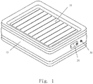
- Fig. 1 is a perspective view of an inflatable bed according to the present invention.
- Fig. 2 is a front view of the inflatable bed according to the present invention.
- Fig. 3 is a right view of the inflatable bed according to the present invention.
- Fig. 4 is a top view of the inflatable bed according to the present invention.
- Fig. 5 is a sectional view of a first embodiment taken along line A-A in Fig. 4 .
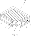
- Fig. 6 is a schematic structural partially sectional view of the first embodiment of the inflatable bed according to the present invention.
- Fig. 7 is an exploded view of the first embodiment of the inflatable bed according to the present invention.
- an inflatable bed 10 is disclosed in the first embodiment according to the present invention, which comprises a top sheet 11, a bottom sheet 12, at least one side wall 13, at least one first tensioning structure 14 and at least one support structure.
- the bottom sheet 12 and the top sheet 11 are disposed vertically at an interval, an upper edge of the side wall 13 is coupled to an outer edge of the top sheet 11, a lower edge of the side wall 13 is coupled to an outer edge of the bottom sheet 12, and an air chamber is formed between the top sheet 11, the bottom sheet 12 and the side wall 13.
- the first tensioning structure 14 is arranged in the air chamber, and an upper end and a lower end of the first tensioning structure 14 are respectively coupled to the top sheet 11 and the bottom sheet 12.
- both the top sheet 11 and the bottom sheet 12 may be configured as a two-layer structure, which can be formed with different patterns by mutually welding at least two sheets.
- a sponge structure is further sandwiched in the two-layer structure.
- Said support structure is arranged in said air chamber herein, said support structure is arranged in the longitudinal direction of at least one of the side walls 13, at least two outside edges of said support structure are respectively coupled to the side wall 13 adjacent thereto, and at least one inside edge of said support structure is coupled to the top sheet 11 or bottom sheet 12 adjacent thereto.
- said support structure comprises a second tensioning structure 15 and a third tensioning structure 16. At least two outside edges of the second tensioning structure 15 are respectively coupled to the side wall 13 adjacent thereto, and at least one inside edge of the second tensioning structure is coupled to the top sheet 11 adjacent thereto.
- the second tensioning structure 15 is configured to limit the upward and lateral bulging of the top sheet 11 and the side wall 13 after said air chamber is inflated.
- the third tensioning structure 16 is configured to limit the respective downward and lateral bulging of the bottom sheet 12 and the side wall 13 after said air chamber is inflated.
- the second tensioning structure 15 comprises at least two first I-beams 151, one outside edge 152 of each first I-beams 151 is coupled to the side wall 13 adjacent thereto, the other inside edge 153 is coupled to the top sheet 11 adjacent thereto, and the at least two first I-beams 151 are disposed at an interval.
- the third tensioning structure 16 comprises at least two second I-beams 161, one outside edge 162 of each second I-beam 161 is coupled to the side wall 13 adjacent thereto, the other inside edge 163 is coupled to the bottom sheet 12 adjacent thereto, and the at least two second I-beams 151 are disposed at an interval.
- the numbers of first I-beams 151 and second I-beams 161 are both two by way of example, but their numbers are not limited by this embodiment, and may be more than two, which also fall within the scope of protection of the present invention.
- the second tensioning structure 15 and the third tensioning structure 16 are preferably disposed at an interval in a perpendicular direction.
- the second tensioning structure 15 and the third tensioning structure 16 divide the respective side wall 13 into five sections, so that the second tensioning structure 15 is configured to limit the upward and lateral bulging of the top sheet 11 and the side wall 13 after said air chamber is inflated, and the third tensioning structure 16 is configured to limit the respective downward and lateral bulging of the bottom sheet 12 and the side wall 13 after said air chamber is inflated.
- the second tensioning structure 15 and the third tensioning structure 16 may also divide the respective side wall 13 into a multi-section structure, such as a four- or six-section structure; this embodiment is merely exemplary and the present invention is not limited thereto, and all the structures with four or more sections fall within the scope of protection of the present invention.
- the at least two first I-beams 151 are arranged spaced apart from each other at a lower surface of the top sheet 11, and the at least two second I-beams 161 are arranged spaced apart from each other at an upper surface of the bottom sheet 12.
- the at least two first I-beams 151 are arranged at an interval on an inner surface of the side wall 13 in a perpendicular direction.
- the at least two second I-beams 161 are arranged at an interval on the inner surface of the side wall 13 in a perpendicular direction.
- the at least two first I-beams 151 as a whole are of a continuous annular structure or a segmental annular structure.
- the at least two second I-beams 161 as a whole are of a continuous annular structure or a segmental annular structure.
- the at least two first I-beams 151 are provided with air holes 154, and an airflow passage is formed in said air chamber through the air holes 154.
- the at least two second I-beams 161 are provided with air holes 164, and an airflow passage is formed in said air chamber through the air holes 164 (as shown in Figs. 7 and 8 ).
- the first tensioning structure 14 of the present invention may employ one or more beams selected from I-beams, coil beams, Y-beams or X-beams.
- the first tensioning structure 14, the second tensioning structure 15 and the third tensioning structure 16 may be all made of thermoplastic plastic sheet, and one or more of the first tensioning structure 14, the second tensioning structure 15 and the third tensioning structure 16 at least partially comprise mesh, laminated plastic sheet or threads.
- the structures thereof may take various forms.
- two side surfaces of said mesh or said threads are at least partially coupled integrally with two opposite s plastic strips, and said mesh and said threads are sandwiched between the two opposite plastic strips.
- two side surfaces of said mesh f or said threads are at least partially coupled integrally with an U-shaped plastic strip, and said mesh and said threads are sandwiched between the U-shaped plastic strip.
- the first tensioning structure 14 is coupled to the top sheet 11 and the bottom sheet 12 by means of high-frequency welding.
- the second tensioning structure 15 is coupled to the top sheet 11 and the side wall 13 by means of high-frequency welding.
- the third tensioning structure 16 is coupled to the bottom sheet 12 and the side wall 13 by means of high-frequency welding.
- the height where the top sheet 11 thereof is located in the inside part of an upper edge of the second tensioning structure 15 is lower than the height where the top sheet 11 is located in the outside part of the upper edge of the second tensioning structure 15.
- the height where the bottom sheet 12 is located in the inside part of a lower edge of the third tensioning structure 16 is lower than the height where the bottom sheet 12 is located in the outside part of the lower edge of the third tensioning structure 16.
- the inflatable bed 10 further comprises a built-in air pump 20, and the built-in air pump 20 is arranged on the side wall 13 and is located between a lower edge of the second tensioning structure 15 and an upper edge of the third tensioning structure 16 for inflating said air chamber.
- the inflatable bed 10 further comprises an air valve 30, and the air valve 30 is arranged on the side wall 13 for the inflation and deflation of the inflatable bed 10.
- Fig. 9 is a sectional view of a second embodiment taken along line A-A in Fig. 4 .
- Fig. 10 is a first exploded view of the second embodiment of the inflatable bed of the present invention.
- Fig. 11 is a second exploded view of the second embodiment of the inflatable bed of the present invention.
- the structure of this embodiment is substantially the same as that of the first embodiment, except that the second tensioning structure 15 comprises at least one first Y-beam 151, wherein two outside edges 152 of the first Y-beam 151 are respectively coupled to the side wall 13 adjacent thereto, and the other inside edge 153 is coupled to the top sheet 11.
- the third tensioning structure 16 comprises at least one second Y-beam 161, wherein two outside edges 162 of the second Y-beam 161 are respectively coupled to the side wall 13 adjacent thereto, and the other inside edge 163 is coupled to the bottom sheet 12.
- the second tensioning structure 15 and the third tensioning structure 16 are preferably disposed at an interval in a perpendicular direction.
- the second tensioning structure 15 and the third tensioning structure 16 divide the respective side wall 13 into five sections, so that the second tensioning structure 15 is configured to limit the upward and lateral bulging of the top sheet 11 and the side wall 13 after said air chamber is inflated, and the third tensioning structure 16 is configured to limit the respective downward and lateral bulging of the bottom sheet 12 and the side wall 13 after said air chamber is inflated.
- the second tensioning structure 15 and the third tensioning structure 16 may also divide the respective side wall 13 into a multi-section structure, such as a four- or six-section structure; this embodiment is merely exemplary and the present invention is not limited thereto, and all the structures with four or more sections fall within the scope of protection of the present invention.
- the two outside edges 152 of the at least one first Y-beam 151 are arranged at an interval on an inner surface of the side wall 13 in a perpendicular direction.
- the two outside edges 162 of the at least one second Y-beam 161 are arranged at an interval on the inner surface of the side wall 13 in a perpendicular direction.
- the at least one first Y-beam 151 as a whole is of a continuous annular structure or a segmental annular structure.
- the at least one second Y-beam 161 as a whole is of a continuous annular structure or a segmental annular structure.
- the at least one first Y-beam 151 is further provided with air holes 154, and an airflow passage is formed in said air chamber through the air holes 154.
- the at least one second Y-beam 161 is further provided with air holes 164, and an airflow passage is formed in said air chamber through the air holes 164 (as shown in Figs. 10 and 11 ).
- Fig. 12 is a first sectional view of a third embodiment taken along line A-A in Fig. 4 .
- Fig. 13 is a second sectional view of the third embodiment taken along line A-A in Fig. 4 .
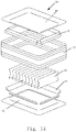
- Fig. 14 is a first exploded view of the third embodiment of the inflatable bed of the present invention.
- Fig. 15 is a second exploded view of the third embodiment of the inflatable bed of the present invention.
- the structure of this embodiment is substantially the same as that of the first embodiment, except that the second tensioning structure 15 comprises at least one first tubular beam 151, wherein the first tubular beam 151 has at least two outside edges 152 respectively coupled to the side wall 13 adjacent thereto, and at least one inside edge 153 is coupled to the top sheet 11.
- the third tensioning structure 16 comprises at least one second tubular beam 161, wherein the second tubular beam 161 has at least two outside edges 162 respectively coupled to the side wall 13 adjacent thereto, and at least one inside edge 163 is coupled to the bottom sheet 12.
- the first tubular beam 151 and the second tubular beam 161 herein may be of various tubular structures, such as a triangular tubular structure, or a quadrilateral tubular structure (as shown in Figs. 13 and 14 ).
- Beam 151 which are coupled to the wall 13 adjacent thereto, are arranged at an interval on an inner surface of the side wall 13 in a perpendicular direction.
- the at least one first tubular beam 151 herein as a whole is of a segmental annular structure.
- the at least one second tubular beam 161 as a whole is of a segmental annular structure (as shown in Figs. 13 and 14 ).
- the second tensioning structure 15 and the third tensioning structure 16 are preferably disposed at an interval in a perpendicular direction.
- the second tensioning structure 15 and the third tensioning structure 16 divide the respective side wall 13 into five sections, so that the second tensioning structure 15 is configured to limit the upward and lateral bulging of the top sheet 11 and the side wall 13 after said air chamber is inflated, and the third tensioning structure 16 is configured to limit the respective downward and lateral bulging of the bottom sheet 12 and the side wall 13 after said air chamber is inflated.
- the second tensioning structure 15 and the third tensioning structure 16 may also divide the respective side wall 13 into a multi-section structure, such as a four- or six-section structure; this embodiment is merely exemplary and the present invention is not limited thereto, and all the structures with four or more sections fall within the scope of protection of the present invention.
- Fig. 16 is a sectional view of a fourth embodiment taken along line A-A in Fig. 4 .
- Fig. 17 is a first exploded view of the fourth embodiment of the inflatable bed of the present invention.
- Fig. 18 is a second exploded view of the fourth embodiment of the inflatable bed of the present invention.
- the structure of this embodiment is substantially the same as that of the first embodiment, except that the second tensioning structure 15 comprises at least one first V-beam 151, wherein two outside edges 152 of the first V-beam 151 are respectively coupled to the side wall 13 adjacent thereto, and the other inside edge 153 is coupled to the top sheet 11.
- the third tensioning structure 16 comprises at least one second V-beam 161, wherein two outside edges 162 of the second V-beam 161 are respectively coupled to the side wall 13 adjacent thereto, and the other inside edge 163 is coupled to the top sheet 11.
- the two outside edges 152 of the at least one first V-beam 151 are arranged at an interval on an inner surface of the side wall 13 in a perpendicular direction.
- the two outside edges 162 of the at least one second V-beam 161 are arranged at an interval on the inner surface of the side wall 13 in a perpendicular direction.
- the at least one first V-beam 151 as a whole is of a continuous annular structure or a segmental annular structure.
- the at least one second V-beam 161 as a whole is of a continuous annular structure or a segmental annular structure.
- the at least one first V-beam 151 is provided with air holes 154, and an airflow passage is formed in said air chamber through the air holes 154.
- the at least one second V-shaped drawstring V-beam 161 is provided with air holes 164, and an airflow passage is formed in said air chamber through the air holes 164.
- the second tensioning structure 15 and the third tensioning structure 16 are preferably disposed at an interval in a perpendicular direction.
- the second tensioning structure 15 and the third tensioning structure 16 divide the respective side wall 13 into five sections, so that the second tensioning structure 15 is configured to limit the upward and lateral bulging of the top sheet 11 and the side wall 13 after said air chamber is inflated, and the third tensioning structure 16 is configured to limit the respective downward and lateral bulging of the bottom sheet 12 and the side wall 13 after said air chamber is inflated.
- the second tensioning structure 15 and the third tensioning structure 16 may also divide the respective side wall 13 into a multi-section structure, such as a four- or six-section structure; this embodiment is merely exemplary and the present invention is not limited thereto, and all the structures with four or more sections fall within the scope of protection of the present invention.
- Fig. 19 is a sectional view of a fifth embodiment taken along line A-A in Fig. 4 .
- Fig. 20 is a schematic structural partially sectional view of the fifth embodiment of the inflatable bed of the present invention.
- the structure of this embodiment is substantially the same as that of the first embodiment, except that the first tensioning structure 14 employs a Y-beam, and the upper and lower ends of the first tensioning structure 14 are respectively coupled to the top sheet 11 and the bottom sheet 12.
- the first tensioning structure 14 employs a Y-beam, and the upper and lower ends of the first tensioning structure 14 are respectively coupled to the top sheet 11 and the bottom sheet 12.
- Several beams in the first tensioning structure 14 are arranged spaced apart from each other.
- the upper end of each beam of the first tensioning structure 14 takes the form of a fork and is coupled to and supports the top sheet 11, and the lower end takes the form of an I-beam and is downwardly coupled to the bottom sheet 12. After said air chamber is inflated, such a structure can effectively limit the respective upward and downward bulging of the top sheet 11 and the bottom sheet 12.
- Fig. 21 is a sectional view of a sixth embodiment taken along line A-A in Fig. 4 .
- the structure of this embodiment is substantially the same as that of the fifth embodiment, except that the first tensioning structure 14 employs an X-shaped drawstring at the upper and lower ends, and the upper and lower ends of the first tensioning structure 14 are respectively coupled to the top sheet 11 and the bottom sheet 12.
- drawstrings in the first tensioning structure 14 are arranged spaced apart from each other.
- the upper end of each drawstring of the first tensioning structure 14 takes the form of a folk and is upwardly coupled to the top sheet 11, and the lower end also takes the form of a folk and is downwardly coupled to the bottom sheet 12. After said air chamber is inflated, such a structure can limit the respective upward and downward bulging of the top sheet 11 and the bottom sheet 12 more effectively.
- Fig. 22 is a sectional view of a seventh embodiment taken along line A-A in Fig. 4 .
- Fig. 23 is a schematic structural partially sectional view of the seventh embodiment of the inflatable bed of the present invention.
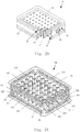
- Fig. 24 is a schematic view of the interior structure of the seventh embodiment of the inflatable bed of the present invention.
- the structure of this embodiment is substantially the same as that of the first embodiment, except that all the drawstrings in the first tensioning structure 14 employ coil beams, and the upper and lower ends of each beam of the first tensioning structure 14 are respectively coupled to the top sheet 11 and the bottom sheet 12.
- Several beams in the first tensioning structure 14 are arranged spaced apart from each other. After said air chamber is inflated, this structure can effectively limit the respective upward and downward bulging of the top sheet 11 and the bottom sheet 12.
- the structural variations in the embodiments may arbitrarily combined, and are not limited to the particular embodiments described above, i.e., the number of beams contained in the second tensioning structure 15 and the number of beams contained in the third tensioning structure 16 are unlimited, which can be adjusted according to actual requirements.
- connection between the beams in the second tensioning structure 15 and the connection between the beams in the third tensioning structure 16 are also not limited to the aforementioned embodiments, as long as the side wall 13 is divided into at least five (or equal to or greater than four) sections, for example, the number of beams in the second tensioning structure 15 and that in the third tensioning structure 16 as well as the connection thereof can be changed so as to divide the side wall 13 into multiple sections such as six or seven sections.
- first tensioning structure 14 can be commonly used in each case, and likewise serve to support the top sheet 11 and the bottom sheet 12, effectively limiting the respective upward and downward bulging of the top sheet 11 and the bottom sheet 12.
- the inflatable bed of the present invention can limit the outward bulging or deformation of the side wall of the inflatable bed by using various types of tensioning structures.
- the structure of the inflatable bed of the present invention effectively overcomes the defect of outward bulging and deformation of the side walls of the inflatable beds and inflatable mattresses having a relatively large height in prior art, making their appearance more attractive.
- the inflatable beds and inflatable mattresses have a good stability, which overcomes the problem of susceptibility of roll-over in the prior art.
- the inflatable bed of the present invention can also prevent the user from rolling down during use.
Landscapes
- Mattresses And Other Support Structures For Chairs And Beds (AREA)
Claims (39)
- Lit gonflable (10), comprenant
une feuille supérieure (11) et une feuille inférieure (12) disposées verticalement à un certain intervalle ; au moins une cloison latérale (13), un bord supérieur de ladite cloison latérale étant couplé à un bord extérieur de ladite feuille supérieure, un bord inférieur de ladite cloison latérale étant couplé à un bord extérieur de ladite feuille inférieure, une chambre à air formée entre ladite feuille supérieure, ladite feuille inférieure et ladite cloison latérale ; au moins une première structure de tension disposée dans ladite chambre à air, une extrémité supérieure et une extrémité inférieure de ladite première structure de tension étant respectivement couplées à ladite feuille supérieure et à ladite feuille inférieure ; et au moins une structure de support disposée dans ladite chambre à air, ladite structure de support étant disposée dans une direction longitudinale d'au moins une desdites cloisons latérales, au moins deux bords extérieurs (152, 162) de ladite structure de support étant respectivement couplés à la cloison latérale adjacente, au moins un bord intérieur (153, 163) de ladite structure de support étant couplé à la feuille supérieure adjacente ou à la feuille inférieure adjacente,
dans lequel ladite structure de support comprend une seconde structure de tension et une troisième structure de tension, au moins deux bords extérieurs de ladite seconde structure de tension sont respectivement couplés à la cloison latérale adjacente, au moins un bord intérieur de la seconde structure de tension est couplé à la feuille supérieure adjacente ; et
au moins deux bords extérieurs de ladite troisième structure de tension sont respectivement couplés à la cloison latérale adjacente, au moins un bord intérieur de ladite troisième structure de tension est couplé à la feuille inférieure adjacente. - Lit gonflable selon la revendication 1, dans lequel ladite seconde structure de tension et ladite troisième structure de tension sont respectivement pourvues d'une pluralité d'orifices d'air, à travers lesquels un passage d'écoulement d'air est formé dans ladite chambre à air.
- Lit gonflable selon la revendication 1, dans lequel ladite seconde structure de tension et ladite troisième structure de tension sont disposées à un certain intervalle dans une direction perpendiculaire.
- Lit gonflable selon la revendication 1, dans lequel ladite seconde structure de tension comprend au moins deux premières traverses en I, un bord extérieur et un bord intérieur de chacune desdites premières traverses en I sont respectivement couplés à ladite cloison latérale adjacente et à ladite feuille supérieure adjacente, les au moins deux premières traverses en I sont disposées à un certain intervalle.
- Lit gonflable selon la revendication 1, dans lequel ladite troisième structure de tension comprend au moins deux secondes traverses en I, un bord extérieur et un bord intérieur de chacune desdites secondes traverses en I sont respectivement couplés à la cloison latérale adjacente et à ladite feuille inférieure adjacente, les au moins deux secondes traverses en I sont disposées à un certain intervalle.
- Lit gonflable selon la revendication 1, dans lequel ladite seconde structure de tension comprend au moins une première traverse en Y, dans lequel deux bords extérieurs de ladite première traverse en Y sont respectivement couplés à la cloison latérale adjacente, un bord intérieur est couplé à ladite feuille supérieure.
- Lit gonflable selon la revendication 1, dans lequel ladite troisième structure de tension comprend au moins une seconde traverse en Y, dans lequel deux bords extérieurs de ladite seconde traverse en Y sont respectivement couplés à la cloison latérale adjacente, un bord intérieur est couplé à ladite feuille inférieure.
- Lit gonflable selon la revendication 1, dans lequel ladite seconde structure de tension comprend au moins une première traverse tubulaire, comportant au moins deux bords extérieurs respectivement couplés à la cloison latérale adjacente, au moins un bord intérieur est couplé à ladite feuille supérieure.
- Lit gonflable selon la revendication 1, dans lequel ladite troisième structure de tension comprend au moins une seconde traverse tubulaire, comprenant au moins deux bords extérieurs respectivement couplés à la cloison latérale adjacente, au moins un bord intérieur est couplé à ladite feuille inférieure.
- Lit gonflable selon la revendication 1, dans lequel ladite seconde structure de tension comprend au moins une première traverse en V, dans lequel deux bords extérieurs de ladite première traverse en V sont respectivement couplés à la cloison latérale adjacente, un bord intérieur est couplé à ladite feuille supérieure.
- Lit gonflable selon la revendication 1, dans lequel ladite troisième structure de tension comprend au moins une seconde traverse en V, dans lequel deux bords extérieurs de ladite seconde traverse en V sont respectivement couplés à la cloison latérale adjacente, un bord intérieur est couplé à ladite feuille inférieure.
- Lit gonflable selon la revendication 4, dans lequel lesdites au moins deux premières traverses en I sont espacées l'une de l'autre en correspondance d'une surface inférieure de ladite feuille supérieure.
- Lit gonflable selon la revendication 5, dans lequel lesdites au moins deux secondes traverses en I sont espacées l'une de l'autre en correspondance d'une surface supérieure de ladite feuille inférieure.
- Lit gonflable selon la revendication 4, dans lequel lesdites au moins deux premières traverses en I sont disposées à un certain intervalle sur une surface intérieure de ladite cloison latérale dans une direction perpendiculaire.
- Lit gonflable selon la revendication 5, dans lequel lesdites au moins deux secondes traverses en I sont disposées à un certain intervalle sur la surface intérieure de ladite cloison latérale dans une direction perpendiculaire.
- Lit gonflable selon la revendication 6, dans lequel les deux bords extérieurs de ladite au moins une première traverse en Y sont disposés à un certain intervalle sur une surface intérieure de ladite cloison latérale dans une direction perpendiculaire.
- Lit gonflable selon la revendication 7, dans lequel les deux bords extérieurs de ladite au moins une seconde traverse en Y sont disposées à un certain intervalle sur la surface intérieure de ladite cloison latérale dans une direction perpendiculaire.
- Lit gonflable selon la revendication 8, dans lequel lesdits au moins deux bords extérieurs de ladite au moins une première traverse tubulaire, étant couplés à la cloison latérale adjacente, sont disposés à un certain intervalle sur une surface intérieure de ladite cloison latérale dans une direction perpendiculaire.
- Lit gonflable selon la revendication 9, dans lequel lesdits au moins deux bords extérieurs de ladite au moins une seconde traverse tubulaire, étant couplés à la cloison latérale adjacente, sont disposés à un certain intervalle sur la surface intérieure de ladite cloison latérale dans une direction perpendiculaire.
- Lit gonflable selon la revendication 10, dans lequel les deux bords extérieurs de ladite au moins une première traverse en V sont disposés à un certain intervalle sur une surface intérieure de ladite cloison latérale dans une direction perpendiculaire.
- Lit gonflable selon la revendication 11, dans lequel les deux bords extérieurs de ladite au moins une seconde traverse en V sont disposés à un certain intervalle sur la surface intérieure de ladite cloison latérale dans une direction perpendiculaire.
- Lit gonflable selon la revendication 4, dans lequel lesdites au moins deux premières traverses en V, dans leur ensemble, ont une structure annulaire continue ou une structure annulaire segmentaire.
- Lit gonflable selon la revendication 5, dans lequel lesdites au moins deux secondes traverses en I, dans leur ensemble, ont une structure annulaire continue ou une structure annulaire segmentaire.
- Lit gonflable selon la revendication 6, dans lequel ladite au moins une première traverse en Y, dans son ensemble, a une structure annulaire continue ou une structure annulaire segmentaire.
- Lit gonflable selon la revendication 7, dans lequel ladite au moins une seconde traverse en Y, dans son ensemble, a une structure annulaire continue ou une structure annulaire segmentaire.
- Lit gonflable selon la revendication 8, dans lequel ladite au moins une première traverse tubulaire, dans son ensemble, a une structure annulaire segmentaire.
- Lit gonflable selon la revendication 9, dans lequel ladite au moins une seconde traverse tubulaire, dans son ensemble, a une structure annulaire segmentaire.
- Lit gonflable selon la revendication 10, dans lequel ladite au moins une première traverse en V, dans son ensemble, a une structure annulaire continue ou une structure annulaire segmentaire.
- Lit gonflable selon la revendication 11, dans lequel ladite au moins une seconde traverse en V, dans son ensemble, a une structure annulaire continue ou une structure annulaire segmentaire.
- Lit gonflable selon la revendication 1, dans lequel ladite première structure de tension est une ou plusieurs traverses sélectionnée(s) à partir des traverses en I, des traverses à spirales, des traverses en Y ou des traverses en X.
- Lit gonflable selon la revendication 1, dans lequel ladite première structure de tension, ladite seconde structure de tension et ladite troisième structure de tension sont toutes composées d'une feuille plastique thermoplastique.
- Lit gonflable selon la revendication 1, dans lequel une ou plusieurs desdites première structure de tension, seconde structure de tension et troisième structure de tension comprennent au moins en partie un maillage, une feuille plastique stratifiée ou un filetage.
- Lit gonflable selon la revendication 32, dans lequel deux surfaces latérales dudit maillage ou dudit filetage sont au moins partiellement couplées de façon solidaire à deux bandes plastiques opposées, ledit maillage et ledit filetage sont pris en sandwich entre les deux bandes plastiques opposées.
- Lit gonflable selon la revendication 32, dans lequel deux surfaces latérales dudit maillage ou dudit filetage sont au moins partiellement couplées de façon solidaire à une bande plastique en U, ledit maillage et ledit filetage sont pris en sandwich entre la bande plastique en U.
- Lit gonflable selon la revendication 1, dans lequel ladite première structure de tension est couplée auxdites feuilles supérieure et inférieure au moyen d'un soudage par haute fréquence ; ladite seconde structure de tension est couplée à ladite feuille supérieure et à ladite cloison latérale au moyen d'un soudage par haute fréquence ; et ladite troisième structure de tension est couplée à ladite feuille inférieure et à ladite cloison latérale au moyen d'un soudage par haute fréquence.
- Lit gonflable selon la revendication 1, dans lequel l'emplacement où ladite feuille supérieure est située dans la partie intérieure d'un bord supérieur de ladite seconde structure de tension est plus bas que l'emplacement où ladite feuille supérieure est située dans la partie extérieure du bord supérieur de ladite seconde structure de tension.
- Lit gonflable selon la revendication 1, dans lequel l'emplacement où ladite feuille inférieure est située dans la partie intérieure d'un bord inférieur de ladite troisième structure de tension est plus bas que l'emplacement où ladite feuille inférieure est située dans la partie extérieure du bord inférieur de ladite troisième structure de tension.
- Lit gonflable selon la revendication 1, dans lequel ledit lit gonflable comprend de plus une pompe à air intégrée étant disposée sur ladite cloison latérale et située entre un bord inférieur de ladite seconde structure de tension et un bord supérieur de ladite troisième structure de tension pour gonfler ladite chambre à air.
- Lit gonflable selon la revendication 1, dans lequel ledit lit gonflable comprend de plus un clapet d'air étant disposé sur ladite cloison latérale pour le gonflage ou le dégonflage dudit lit gonflable.
Applications Claiming Priority (2)
| Application Number | Priority Date | Filing Date | Title |
|---|---|---|---|
| CN201620031074.6U CN205457538U (zh) | 2016-01-13 | 2016-01-13 | 充气床 |
| CN201610020533.5A CN106963177A (zh) | 2016-01-13 | 2016-01-13 | 充气床 |
Publications (2)
| Publication Number | Publication Date |
|---|---|
| EP3192401A1 EP3192401A1 (fr) | 2017-07-19 |
| EP3192401B1 true EP3192401B1 (fr) | 2018-09-19 |
Family
ID=57042731
Family Applications (1)
| Application Number | Title | Priority Date | Filing Date |
|---|---|---|---|
| EP16191360.3A Active EP3192401B1 (fr) | 2016-01-13 | 2016-09-29 | Lit gonflable |
Country Status (2)
| Country | Link |
|---|---|
| US (3) | US10687633B2 (fr) |
| EP (1) | EP3192401B1 (fr) |
Families Citing this family (48)
| Publication number | Priority date | Publication date | Assignee | Title |
|---|---|---|---|---|
| EP3192401B1 (fr) * | 2016-01-13 | 2018-09-19 | Bestway Inflatables & Material Corp | Lit gonflable |
| CN105615393A (zh) * | 2016-02-23 | 2016-06-01 | 浙江大自然旅游用品有限公司 | 充气产品及充气产品熔接工艺 |
| CN107536331A (zh) * | 2017-09-20 | 2018-01-05 | 明达实业(厦门)有限公司 | 一种充气床及其制造方法 |
| EP3524099B1 (fr) * | 2018-02-12 | 2021-07-21 | Bestway Inflatables & Material Corp. | Produit gonflable |
| DE102019111154A1 (de) * | 2018-05-02 | 2019-11-07 | Brilliant Product Design Co., Ltd. | Matratzenstruktur |
| CN108775836A (zh) * | 2018-06-11 | 2018-11-09 | 浙江解放机械制造有限公司 | 一种充气外形控制结构 |
| US20200113342A1 (en) * | 2018-10-11 | 2020-04-16 | Bradley Craig Stone | Air mattress systems with adjustable inclination |
| CN209807775U (zh) * | 2018-12-18 | 2019-12-20 | 贝尔格莱维亚伍德有限公司 | 可充气气垫 |
| US12279700B2 (en) * | 2018-12-18 | 2025-04-22 | Belgravia Wood Limited | Internal support system for an inflatable air mattress |
| CN209875430U (zh) * | 2019-02-12 | 2019-12-31 | 上海荣威塑胶工业有限公司 | 智能电动气泵 |
| USD931015S1 (en) * | 2019-06-25 | 2021-09-21 | Jae Duk Lee | Bed frame |
| USD913719S1 (en) * | 2019-10-31 | 2021-03-23 | Pineapple Contracts Unlimited | Bed |
| US12075917B2 (en) * | 2019-12-05 | 2024-09-03 | Dongguan Hongyu Plastic Co., Ltd | Inflatable bed |
| USD982359S1 (en) * | 2019-12-10 | 2023-04-04 | Dongguan Hongyu Plastic Co., Ltd | Air mattress |
| CN212521331U (zh) * | 2020-06-08 | 2021-02-12 | 江苏吉龙运动休闲用品有限公司 | 一种充气床 |
| US10945533B1 (en) * | 2020-06-14 | 2021-03-16 | Dongguan Hongyu Plastic Co., Ltd | Air bed |
| DK3991610T3 (da) | 2020-10-28 | 2024-04-22 | Bestway Inflatables & Mat Corp | Oppustelig seng |
| CN213786422U (zh) * | 2020-10-30 | 2021-07-27 | 上海荣威塑胶工业有限公司 | 双层充气床 |
| US20220202197A1 (en) * | 2020-12-31 | 2022-06-30 | Team Worldwide Corporation | Air mattress |
| CN214711676U (zh) * | 2021-03-15 | 2021-11-16 | 东莞市红宇塑胶有限公司 | 双层气垫床 |
| CN215686219U (zh) * | 2021-07-26 | 2022-02-01 | 浙江大自然户外用品股份有限公司 | 充气床垫及床 |
| CN215686133U (zh) * | 2021-09-29 | 2022-02-01 | 陈焕 | 一种新型气垫床 |
| USD979984S1 (en) * | 2021-10-13 | 2023-03-07 | Dongguan Hongyu Plactic Co., Ltd | Airbed |
| CN218500349U (zh) * | 2021-10-29 | 2023-02-21 | 上海荣威塑胶工业有限公司 | 侧面压花充气产品 |
| CN113876144A (zh) * | 2021-11-18 | 2022-01-04 | 义乌市景田户外用品有限公司 | 充气垫 |
| CN216494492U (zh) * | 2021-12-29 | 2022-05-13 | 东莞市红宇塑胶有限公司 | 双层充气床 |
| US11910930B2 (en) * | 2022-01-12 | 2024-02-27 | Dongguan Hongyu Plastic Rubber Co., Ltd. | Airbed with air pump |
| CN216907431U (zh) * | 2022-03-29 | 2022-07-08 | 东莞市红宇塑胶有限公司 | 皮卡车床垫 |
| US20240016300A1 (en) * | 2022-07-18 | 2024-01-18 | Bo Zhong | Electric inflatable bed with multiple air chambers |
| USD1067687S1 (en) * | 2022-11-04 | 2025-03-25 | Wuzhou Baofeng Plastic Products Co., Ltd. | Inflatable mattress |
| WO2024100627A1 (fr) * | 2022-11-10 | 2024-05-16 | Intex Industries Xiamen Co. Ltd. | Structure de corps gonflable |
| CN219396794U (zh) * | 2023-03-07 | 2023-07-25 | 东莞市红宇塑胶有限公司 | 新型充气床 |
| US12226020B2 (en) | 2023-03-13 | 2025-02-18 | Dongguan Hongyu Plastic Co., Ltd. | Inflatable bed |
| USD1018141S1 (en) * | 2023-03-14 | 2024-03-19 | Dongguan Hongyu Plastic Co., Ltd | Air bed |
| CN220069297U (zh) * | 2023-05-17 | 2023-11-24 | 佛山市天盛休闲运动用品有限公司 | 一种充气床 |
| US20240407561A1 (en) * | 2023-06-12 | 2024-12-12 | Team Worldwide Corporation | Inflatable Product |
| CN220675634U (zh) * | 2023-07-29 | 2024-03-29 | 唐小三 | 一种网斜片充气床 |
| CN220713473U (zh) * | 2023-08-10 | 2024-04-05 | 东莞市红宇塑胶有限公司 | 一种充气床 |
| CN221129403U (zh) * | 2023-09-12 | 2024-06-14 | 深圳市锐掣科技创新有限公司 | 一种充气床 |
| CN221410872U (zh) * | 2023-09-28 | 2024-07-26 | 佛山市天盛休闲运动用品有限公司 | 一种充气床 |
| CN221489549U (zh) * | 2023-12-18 | 2024-08-09 | 东莞市红宇塑胶有限公司 | 一种充气床垫 |
| CN117752193A (zh) * | 2024-01-10 | 2024-03-26 | 旺利塑胶电子(惠州)有限公司 | 一种多层次和多腔室的充气床 |
| CN222091248U (zh) * | 2024-02-04 | 2024-12-03 | 东莞市红宇塑胶有限公司 | 一种具有透气性能的充气床 |
| US12102235B1 (en) * | 2024-03-15 | 2024-10-01 | Xiaoyao Luo | Anti-collapse inflatable air mattress |
| USD1058243S1 (en) * | 2024-08-03 | 2025-01-21 | Dongguan Hongyu Plastic Co., Ltd. | Inflatable bed |
| USD1059085S1 (en) * | 2024-08-03 | 2025-01-28 | Dongguan Hongyu Plastic Co., Ltd. | Inflatable bed |
| TWI891574B (zh) | 2024-11-22 | 2025-07-21 | 聖州企業股份有限公司 | 內膽分離式充氣墊結構 |
| US12484707B1 (en) * | 2025-03-14 | 2025-12-02 | Reestar International Limited | Inflatable bed |
Citations (14)
| Publication number | Priority date | Publication date | Assignee | Title |
|---|---|---|---|---|
| GB434098A (en) | 1933-11-21 | 1935-08-26 | P B Cow & Company Ltd | Improvements in or relating to pneumatic bags or mattresses |
| US4941223A (en) | 1988-02-19 | 1990-07-17 | Santo Philip J | Waterbed mattress marginal perimeter air support and method of manufacture thereof |
| US5669091A (en) | 1996-03-15 | 1997-09-23 | Chung; Ming-Chun | Structure of water bed |
| US6568013B2 (en) | 1999-01-08 | 2003-05-27 | Hill-Rom Services, Inc. | Fluid mattress assembly with check valves |
| US6671910B2 (en) | 2001-12-05 | 2004-01-06 | Intex Recreation Corp. | Inflatable bed |
| US6701559B2 (en) | 2001-08-01 | 2004-03-09 | Aero Products International, Inc. | Increased height inflatable support system |
| US7039972B2 (en) | 2000-05-17 | 2006-05-09 | Chaffee Robert B | Inflatable device with recessed fluid controller and modified adjustment device |
| US20070277324A1 (en) | 2006-06-02 | 2007-12-06 | Bestway Inflatables & Material Corp. | Beam construction of air mattress |
| FR2914545A3 (fr) | 2007-04-04 | 2008-10-10 | Rong Jyh Song | Lit gonflable |
| CN203137719U (zh) | 2013-01-25 | 2013-08-21 | 明达实业(厦门)有限公司 | 充气产品气室斜拉固定结构 |
| WO2013130117A1 (fr) | 2012-03-02 | 2013-09-06 | Intex Recreation Corporation | Structure de tension interne utilisable avec des dispositifs gonflables |
| US20150201760A1 (en) | 2014-01-17 | 2015-07-23 | Intex Recreation Corporation | Multi-chamber inflatable device |
| US20150335164A1 (en) | 2014-05-23 | 2015-11-26 | Bestway Inflatables & Material Corp. | Internal supports for inflatable products |
| US9254047B1 (en) | 2006-07-14 | 2016-02-09 | William Schermel | Reinforced vinyl air mattress |
Family Cites Families (27)
| Publication number | Priority date | Publication date | Assignee | Title |
|---|---|---|---|---|
| GB134098A (fr) | 1900-01-01 | |||
| US2360715A (en) | 1942-05-14 | 1944-10-17 | Airtress Corp Of America | Pneumatic cushion |
| US3008213A (en) * | 1957-01-22 | 1961-11-14 | Us Rubber Co | Method of making an inflatable fabric |
| JPS5150166A (en) * | 1974-10-25 | 1976-05-01 | Katsuji Nishikata | Kureen aruiha hoisutotoonokanshoosoochi |
| US4558476A (en) * | 1983-10-11 | 1985-12-17 | Linder Philip C | Flotation type apparatus and method for supporting a load |
| US4541135A (en) | 1984-04-16 | 1985-09-17 | Victor Karpov | Air mattress |
| US6990700B2 (en) | 2001-06-22 | 2006-01-31 | Team Worldwide Corporation | Inflatable product provided with electric air pump |
| US6754926B2 (en) | 2002-04-30 | 2004-06-29 | Cheng-Chung Wang | Inflatable bed |
| US7089618B1 (en) | 2003-06-18 | 2006-08-15 | The Coleman Company, Inc. | Air mattress |
| CN2694837Y (zh) | 2004-04-16 | 2005-04-27 | 巫新财 | 多层式空气床 |
| US20050273938A1 (en) | 2004-06-09 | 2005-12-15 | The Coleman Company, Inc. | Airbed utilizing extruded coils |
| CN2706070Y (zh) | 2004-06-16 | 2005-06-29 | 明达塑胶(厦门)有限公司 | 具有吸地功能的充气床 |
| CN2822385Y (zh) | 2005-04-04 | 2006-10-04 | 柏威美国有限公司 | 一种稳定支撑结构的充气床 |
| US20060265810A1 (en) | 2005-05-27 | 2006-11-30 | Hsin-Tsai Wu | Inflatable air mattress pull band |
| US7337485B2 (en) | 2005-08-31 | 2008-03-04 | The Coleman Company, Inc. | Double high airbed utilizing coils |
| US7353555B2 (en) * | 2005-12-07 | 2008-04-08 | Ideal Time Consultants Limited | Inflatable mattress assembly |
| CN200991028Y (zh) | 2006-12-26 | 2007-12-19 | 巫新财 | 一种带游戏装置的充气床垫 |
| CN201097864Y (zh) | 2007-11-07 | 2008-08-13 | 宋荣治 | 充气床 |
| BR202012024726U2 (pt) | 2011-12-09 | 2015-10-06 | Minetec Sa | memória descritiva |
| CN202681275U (zh) * | 2011-12-13 | 2013-01-23 | 嘉翰德实业股份有限公司 | 空气床 |
| CN202751069U (zh) | 2012-07-25 | 2013-02-27 | 上海荣威塑胶工业有限公司 | 一种双层充气床的结构 |
| CN103110297A (zh) | 2013-01-25 | 2013-05-22 | 明达实业(厦门)有限公司 | 充气产品加固结构 |
| CN103600502A (zh) * | 2013-11-25 | 2014-02-26 | 明达实业(厦门)有限公司 | 一种充气产品熔着工艺 |
| CN205457538U (zh) | 2016-01-13 | 2016-08-17 | 上海荣威塑胶工业有限公司 | 充气床 |
| EP3192401B1 (fr) * | 2016-01-13 | 2018-09-19 | Bestway Inflatables & Material Corp | Lit gonflable |
| US20170273472A1 (en) * | 2016-03-25 | 2017-09-28 | Bestway Inflatables & Material Corp. | Inflatable mattress |
| US20190290013A1 (en) * | 2018-01-26 | 2019-09-26 | Dennis M. Boyd | Mattress topper |
-
2016
- 2016-09-29 EP EP16191360.3A patent/EP3192401B1/fr active Active
- 2016-09-29 US US15/280,513 patent/US10687633B2/en active Active
-
2020
- 2020-06-22 US US16/907,893 patent/US11564505B2/en active Active
-
2022
- 2022-12-08 US US18/077,400 patent/US12364340B2/en active Active
Patent Citations (14)
| Publication number | Priority date | Publication date | Assignee | Title |
|---|---|---|---|---|
| GB434098A (en) | 1933-11-21 | 1935-08-26 | P B Cow & Company Ltd | Improvements in or relating to pneumatic bags or mattresses |
| US4941223A (en) | 1988-02-19 | 1990-07-17 | Santo Philip J | Waterbed mattress marginal perimeter air support and method of manufacture thereof |
| US5669091A (en) | 1996-03-15 | 1997-09-23 | Chung; Ming-Chun | Structure of water bed |
| US6568013B2 (en) | 1999-01-08 | 2003-05-27 | Hill-Rom Services, Inc. | Fluid mattress assembly with check valves |
| US7039972B2 (en) | 2000-05-17 | 2006-05-09 | Chaffee Robert B | Inflatable device with recessed fluid controller and modified adjustment device |
| US6701559B2 (en) | 2001-08-01 | 2004-03-09 | Aero Products International, Inc. | Increased height inflatable support system |
| US6671910B2 (en) | 2001-12-05 | 2004-01-06 | Intex Recreation Corp. | Inflatable bed |
| US20070277324A1 (en) | 2006-06-02 | 2007-12-06 | Bestway Inflatables & Material Corp. | Beam construction of air mattress |
| US9254047B1 (en) | 2006-07-14 | 2016-02-09 | William Schermel | Reinforced vinyl air mattress |
| FR2914545A3 (fr) | 2007-04-04 | 2008-10-10 | Rong Jyh Song | Lit gonflable |
| WO2013130117A1 (fr) | 2012-03-02 | 2013-09-06 | Intex Recreation Corporation | Structure de tension interne utilisable avec des dispositifs gonflables |
| CN203137719U (zh) | 2013-01-25 | 2013-08-21 | 明达实业(厦门)有限公司 | 充气产品气室斜拉固定结构 |
| US20150201760A1 (en) | 2014-01-17 | 2015-07-23 | Intex Recreation Corporation | Multi-chamber inflatable device |
| US20150335164A1 (en) | 2014-05-23 | 2015-11-26 | Bestway Inflatables & Material Corp. | Internal supports for inflatable products |
Also Published As
| Publication number | Publication date |
|---|---|
| US20170196368A1 (en) | 2017-07-13 |
| US11564505B2 (en) | 2023-01-31 |
| US20230122867A1 (en) | 2023-04-20 |
| US20200315366A1 (en) | 2020-10-08 |
| EP3192401A1 (fr) | 2017-07-19 |
| US12364340B2 (en) | 2025-07-22 |
| US10687633B2 (en) | 2020-06-23 |
Similar Documents
| Publication | Publication Date | Title |
|---|---|---|
| US12364340B2 (en) | Inflatable bed | |
| US7337485B2 (en) | Double high airbed utilizing coils | |
| US7353555B2 (en) | Inflatable mattress assembly | |
| CN201097864Y (zh) | 充气床 | |
| US9247827B2 (en) | Multi-chamber inflatable device | |
| US6463610B1 (en) | Multi-chamber airbed | |
| US20090085393A1 (en) | Inflatable Chair With Cushion Top | |
| CN203852092U (zh) | 一种充气产品的拉带结构 | |
| US11918120B2 (en) | Inflatable bed | |
| US20210259434A1 (en) | Inflatable mattress with improved structure | |
| US9376860B2 (en) | Double pleat cellular shade element | |
| CN106963177A (zh) | 充气床 | |
| CA2901945A1 (fr) | Matelas de camping pliant autogonflant | |
| US20050273938A1 (en) | Airbed utilizing extruded coils | |
| CN204326603U (zh) | 一种具有复数个储水腔的支架水池 | |
| US20220287475A1 (en) | Double-layer air cushion bed | |
| CN207855428U (zh) | 一种高层充气床的加固结构 | |
| US20190231085A1 (en) | Inflatable product and tensioning beam thereof | |
| CN205457538U (zh) | 充气床 | |
| US20060163934A1 (en) | Outdoor chair | |
| CN111265060A (zh) | 一种充气床 | |
| US20050081299A1 (en) | Inflatable bed | |
| TWI891574B (zh) | 內膽分離式充氣墊結構 | |
| CN211933404U (zh) | 一种充气床 | |
| CN224120011U (zh) | 一种充气帐篷的分隔式气柱结构 |
Legal Events
| Date | Code | Title | Description |
|---|---|---|---|
| PUAI | Public reference made under article 153(3) epc to a published international application that has entered the european phase |
Free format text: ORIGINAL CODE: 0009012 |
|
| STAA | Information on the status of an ep patent application or granted ep patent |
Free format text: STATUS: THE APPLICATION HAS BEEN PUBLISHED |
|
| AK | Designated contracting states |
Kind code of ref document: A1 Designated state(s): AL AT BE BG CH CY CZ DE DK EE ES FI FR GB GR HR HU IE IS IT LI LT LU LV MC MK MT NL NO PL PT RO RS SE SI SK SM TR |
|
| AX | Request for extension of the european patent |
Extension state: BA ME |
|
| STAA | Information on the status of an ep patent application or granted ep patent |
Free format text: STATUS: REQUEST FOR EXAMINATION WAS MADE |
|
| 17P | Request for examination filed |
Effective date: 20180119 |
|
| RBV | Designated contracting states (corrected) |
Designated state(s): AL AT BE BG CH CY CZ DE DK EE ES FI FR GB GR HR HU IE IS IT LI LT LU LV MC MK MT NL NO PL PT RO RS SE SI SK SM TR |
|
| GRAP | Despatch of communication of intention to grant a patent |
Free format text: ORIGINAL CODE: EPIDOSNIGR1 |
|
| STAA | Information on the status of an ep patent application or granted ep patent |
Free format text: STATUS: GRANT OF PATENT IS INTENDED |
|
| INTG | Intention to grant announced |
Effective date: 20180507 |
|
| GRAS | Grant fee paid |
Free format text: ORIGINAL CODE: EPIDOSNIGR3 |
|
| GRAA | (expected) grant |
Free format text: ORIGINAL CODE: 0009210 |
|
| STAA | Information on the status of an ep patent application or granted ep patent |
Free format text: STATUS: THE PATENT HAS BEEN GRANTED |
|
| RIN1 | Information on inventor provided before grant (corrected) |
Inventor name: LIU, FENG |
|
| AK | Designated contracting states |
Kind code of ref document: B1 Designated state(s): AL AT BE BG CH CY CZ DE DK EE ES FI FR GB GR HR HU IE IS IT LI LT LU LV MC MK MT NL NO PL PT RO RS SE SI SK SM TR |
|
| REG | Reference to a national code |
Ref country code: GB Ref legal event code: FG4D |
|
| REG | Reference to a national code |
Ref country code: CH Ref legal event code: EP |
|
| REG | Reference to a national code |
Ref country code: FR Ref legal event code: PLFP Year of fee payment: 3 |
|
| REG | Reference to a national code |
Ref country code: AT Ref legal event code: REF Ref document number: 1042272 Country of ref document: AT Kind code of ref document: T Effective date: 20181015 |
|
| REG | Reference to a national code |
Ref country code: IE Ref legal event code: FG4D |
|
| REG | Reference to a national code |
Ref country code: DE Ref legal event code: R096 Ref document number: 602016005699 Country of ref document: DE |
|
| REG | Reference to a national code |
Ref country code: NL Ref legal event code: MP Effective date: 20180919 |
|
| PG25 | Lapsed in a contracting state [announced via postgrant information from national office to epo] |
Ref country code: GR Free format text: LAPSE BECAUSE OF FAILURE TO SUBMIT A TRANSLATION OF THE DESCRIPTION OR TO PAY THE FEE WITHIN THE PRESCRIBED TIME-LIMIT Effective date: 20181220 Ref country code: RS Free format text: LAPSE BECAUSE OF FAILURE TO SUBMIT A TRANSLATION OF THE DESCRIPTION OR TO PAY THE FEE WITHIN THE PRESCRIBED TIME-LIMIT Effective date: 20180919 Ref country code: LT Free format text: LAPSE BECAUSE OF FAILURE TO SUBMIT A TRANSLATION OF THE DESCRIPTION OR TO PAY THE FEE WITHIN THE PRESCRIBED TIME-LIMIT Effective date: 20180919 Ref country code: SE Free format text: LAPSE BECAUSE OF FAILURE TO SUBMIT A TRANSLATION OF THE DESCRIPTION OR TO PAY THE FEE WITHIN THE PRESCRIBED TIME-LIMIT Effective date: 20180919 Ref country code: BG Free format text: LAPSE BECAUSE OF FAILURE TO SUBMIT A TRANSLATION OF THE DESCRIPTION OR TO PAY THE FEE WITHIN THE PRESCRIBED TIME-LIMIT Effective date: 20181219 Ref country code: FI Free format text: LAPSE BECAUSE OF FAILURE TO SUBMIT A TRANSLATION OF THE DESCRIPTION OR TO PAY THE FEE WITHIN THE PRESCRIBED TIME-LIMIT Effective date: 20180919 Ref country code: NO Free format text: LAPSE BECAUSE OF FAILURE TO SUBMIT A TRANSLATION OF THE DESCRIPTION OR TO PAY THE FEE WITHIN THE PRESCRIBED TIME-LIMIT Effective date: 20181219 |
|
| REG | Reference to a national code |
Ref country code: LT Ref legal event code: MG4D |
|
| PG25 | Lapsed in a contracting state [announced via postgrant information from national office to epo] |
Ref country code: LV Free format text: LAPSE BECAUSE OF FAILURE TO SUBMIT A TRANSLATION OF THE DESCRIPTION OR TO PAY THE FEE WITHIN THE PRESCRIBED TIME-LIMIT Effective date: 20180919 Ref country code: HR Free format text: LAPSE BECAUSE OF FAILURE TO SUBMIT A TRANSLATION OF THE DESCRIPTION OR TO PAY THE FEE WITHIN THE PRESCRIBED TIME-LIMIT Effective date: 20180919 Ref country code: AL Free format text: LAPSE BECAUSE OF FAILURE TO SUBMIT A TRANSLATION OF THE DESCRIPTION OR TO PAY THE FEE WITHIN THE PRESCRIBED TIME-LIMIT Effective date: 20180919 |
|
| REG | Reference to a national code |
Ref country code: AT Ref legal event code: MK05 Ref document number: 1042272 Country of ref document: AT Kind code of ref document: T Effective date: 20180919 |
|
| PG25 | Lapsed in a contracting state [announced via postgrant information from national office to epo] |
Ref country code: NL Free format text: LAPSE BECAUSE OF FAILURE TO SUBMIT A TRANSLATION OF THE DESCRIPTION OR TO PAY THE FEE WITHIN THE PRESCRIBED TIME-LIMIT Effective date: 20180919 Ref country code: ES Free format text: LAPSE BECAUSE OF FAILURE TO SUBMIT A TRANSLATION OF THE DESCRIPTION OR TO PAY THE FEE WITHIN THE PRESCRIBED TIME-LIMIT Effective date: 20180919 Ref country code: EE Free format text: LAPSE BECAUSE OF FAILURE TO SUBMIT A TRANSLATION OF THE DESCRIPTION OR TO PAY THE FEE WITHIN THE PRESCRIBED TIME-LIMIT Effective date: 20180919 Ref country code: AT Free format text: LAPSE BECAUSE OF FAILURE TO SUBMIT A TRANSLATION OF THE DESCRIPTION OR TO PAY THE FEE WITHIN THE PRESCRIBED TIME-LIMIT Effective date: 20180919 Ref country code: IT Free format text: LAPSE BECAUSE OF FAILURE TO SUBMIT A TRANSLATION OF THE DESCRIPTION OR TO PAY THE FEE WITHIN THE PRESCRIBED TIME-LIMIT Effective date: 20180919 Ref country code: RO Free format text: LAPSE BECAUSE OF FAILURE TO SUBMIT A TRANSLATION OF THE DESCRIPTION OR TO PAY THE FEE WITHIN THE PRESCRIBED TIME-LIMIT Effective date: 20180919 Ref country code: CZ Free format text: LAPSE BECAUSE OF FAILURE TO SUBMIT A TRANSLATION OF THE DESCRIPTION OR TO PAY THE FEE WITHIN THE PRESCRIBED TIME-LIMIT Effective date: 20180919 Ref country code: PL Free format text: LAPSE BECAUSE OF FAILURE TO SUBMIT A TRANSLATION OF THE DESCRIPTION OR TO PAY THE FEE WITHIN THE PRESCRIBED TIME-LIMIT Effective date: 20180919 Ref country code: IS Free format text: LAPSE BECAUSE OF FAILURE TO SUBMIT A TRANSLATION OF THE DESCRIPTION OR TO PAY THE FEE WITHIN THE PRESCRIBED TIME-LIMIT Effective date: 20190119 |
|
| PG25 | Lapsed in a contracting state [announced via postgrant information from national office to epo] |
Ref country code: SK Free format text: LAPSE BECAUSE OF FAILURE TO SUBMIT A TRANSLATION OF THE DESCRIPTION OR TO PAY THE FEE WITHIN THE PRESCRIBED TIME-LIMIT Effective date: 20180919 Ref country code: PT Free format text: LAPSE BECAUSE OF FAILURE TO SUBMIT A TRANSLATION OF THE DESCRIPTION OR TO PAY THE FEE WITHIN THE PRESCRIBED TIME-LIMIT Effective date: 20190119 Ref country code: SM Free format text: LAPSE BECAUSE OF FAILURE TO SUBMIT A TRANSLATION OF THE DESCRIPTION OR TO PAY THE FEE WITHIN THE PRESCRIBED TIME-LIMIT Effective date: 20180919 |
|
| REG | Reference to a national code |
Ref country code: BE Ref legal event code: MM Effective date: 20180930 |
|
| REG | Reference to a national code |
Ref country code: DE Ref legal event code: R026 Ref document number: 602016005699 Country of ref document: DE |
|
| PLBI | Opposition filed |
Free format text: ORIGINAL CODE: 0009260 |
|
| REG | Reference to a national code |
Ref country code: IE Ref legal event code: MM4A |
|
| PG25 | Lapsed in a contracting state [announced via postgrant information from national office to epo] |
Ref country code: LU Free format text: LAPSE BECAUSE OF NON-PAYMENT OF DUE FEES Effective date: 20180929 |
|
| PLAX | Notice of opposition and request to file observation + time limit sent |
Free format text: ORIGINAL CODE: EPIDOSNOBS2 |
|
| 26 | Opposition filed |
Opponent name: INTEX RECREATION CORP. Effective date: 20190617 |
|
| PG25 | Lapsed in a contracting state [announced via postgrant information from national office to epo] |
Ref country code: DK Free format text: LAPSE BECAUSE OF FAILURE TO SUBMIT A TRANSLATION OF THE DESCRIPTION OR TO PAY THE FEE WITHIN THE PRESCRIBED TIME-LIMIT Effective date: 20180919 Ref country code: MC Free format text: LAPSE BECAUSE OF FAILURE TO SUBMIT A TRANSLATION OF THE DESCRIPTION OR TO PAY THE FEE WITHIN THE PRESCRIBED TIME-LIMIT Effective date: 20180919 Ref country code: IE Free format text: LAPSE BECAUSE OF NON-PAYMENT OF DUE FEES Effective date: 20180929 |
|
| PG25 | Lapsed in a contracting state [announced via postgrant information from national office to epo] |
Ref country code: BE Free format text: LAPSE BECAUSE OF NON-PAYMENT OF DUE FEES Effective date: 20180930 |
|
| PLBB | Reply of patent proprietor to notice(s) of opposition received |
Free format text: ORIGINAL CODE: EPIDOSNOBS3 |
|
| PG25 | Lapsed in a contracting state [announced via postgrant information from national office to epo] |
Ref country code: SI Free format text: LAPSE BECAUSE OF FAILURE TO SUBMIT A TRANSLATION OF THE DESCRIPTION OR TO PAY THE FEE WITHIN THE PRESCRIBED TIME-LIMIT Effective date: 20180919 |
|
| PG25 | Lapsed in a contracting state [announced via postgrant information from national office to epo] |
Ref country code: MT Free format text: LAPSE BECAUSE OF NON-PAYMENT OF DUE FEES Effective date: 20180929 |
|
| PG25 | Lapsed in a contracting state [announced via postgrant information from national office to epo] |
Ref country code: TR Free format text: LAPSE BECAUSE OF FAILURE TO SUBMIT A TRANSLATION OF THE DESCRIPTION OR TO PAY THE FEE WITHIN THE PRESCRIBED TIME-LIMIT Effective date: 20180919 |
|
| REG | Reference to a national code |
Ref country code: CH Ref legal event code: PL |
|
| PG25 | Lapsed in a contracting state [announced via postgrant information from national office to epo] |
Ref country code: HU Free format text: LAPSE BECAUSE OF FAILURE TO SUBMIT A TRANSLATION OF THE DESCRIPTION OR TO PAY THE FEE WITHIN THE PRESCRIBED TIME-LIMIT; INVALID AB INITIO Effective date: 20160929 Ref country code: MK Free format text: LAPSE BECAUSE OF NON-PAYMENT OF DUE FEES Effective date: 20180919 Ref country code: CY Free format text: LAPSE BECAUSE OF FAILURE TO SUBMIT A TRANSLATION OF THE DESCRIPTION OR TO PAY THE FEE WITHIN THE PRESCRIBED TIME-LIMIT Effective date: 20180919 |
|
| PG25 | Lapsed in a contracting state [announced via postgrant information from national office to epo] |
Ref country code: LI Free format text: LAPSE BECAUSE OF NON-PAYMENT OF DUE FEES Effective date: 20190930 Ref country code: CH Free format text: LAPSE BECAUSE OF NON-PAYMENT OF DUE FEES Effective date: 20190930 |
|
| PLAB | Opposition data, opponent's data or that of the opponent's representative modified |
Free format text: ORIGINAL CODE: 0009299OPPO |
|
| R26 | Opposition filed (corrected) |
Opponent name: INTEX RECREATION CORP. Effective date: 20190617 |
|
| PLCK | Communication despatched that opposition was rejected |
Free format text: ORIGINAL CODE: EPIDOSNREJ1 |
|
| APBM | Appeal reference recorded |
Free format text: ORIGINAL CODE: EPIDOSNREFNO |
|
| APBP | Date of receipt of notice of appeal recorded |
Free format text: ORIGINAL CODE: EPIDOSNNOA2O |
|
| APAH | Appeal reference modified |
Free format text: ORIGINAL CODE: EPIDOSCREFNO |
|
| APBQ | Date of receipt of statement of grounds of appeal recorded |
Free format text: ORIGINAL CODE: EPIDOSNNOA3O |
|
| REG | Reference to a national code |
Ref country code: DE Ref legal event code: R100 Ref document number: 602016005699 Country of ref document: DE |
|
| APBU | Appeal procedure closed |
Free format text: ORIGINAL CODE: EPIDOSNNOA9O |
|
| PLBN | Opposition rejected |
Free format text: ORIGINAL CODE: 0009273 |
|
| STAA | Information on the status of an ep patent application or granted ep patent |
Free format text: STATUS: OPPOSITION REJECTED |
|
| 27O | Opposition rejected |
Effective date: 20220712 |
|
| PGFP | Annual fee paid to national office [announced via postgrant information from national office to epo] |
Ref country code: DE Payment date: 20250916 Year of fee payment: 10 |
|
| PGFP | Annual fee paid to national office [announced via postgrant information from national office to epo] |
Ref country code: GB Payment date: 20250919 Year of fee payment: 10 |
|
| PGFP | Annual fee paid to national office [announced via postgrant information from national office to epo] |
Ref country code: FR Payment date: 20250929 Year of fee payment: 10 |