EP3192969B1 - Gasturbinentriebwerk komponente mit optimierter geometrie an der leitkante - Google Patents
Gasturbinentriebwerk komponente mit optimierter geometrie an der leitkante Download PDFInfo
- Publication number
- EP3192969B1 EP3192969B1 EP16198828.2A EP16198828A EP3192969B1 EP 3192969 B1 EP3192969 B1 EP 3192969B1 EP 16198828 A EP16198828 A EP 16198828A EP 3192969 B1 EP3192969 B1 EP 3192969B1
- Authority
- EP
- European Patent Office
- Prior art keywords
- gas turbine
- turbine engine
- leading edge
- engine component
- boas
- Prior art date
- Legal status (The legal status is an assumption and is not a legal conclusion. Google has not performed a legal analysis and makes no representation as to the accuracy of the status listed.)
- Active
Links
Images




Classifications
-
- F—MECHANICAL ENGINEERING; LIGHTING; HEATING; WEAPONS; BLASTING
- F01—MACHINES OR ENGINES IN GENERAL; ENGINE PLANTS IN GENERAL; STEAM ENGINES
- F01D—NON-POSITIVE DISPLACEMENT MACHINES OR ENGINES, e.g. STEAM TURBINES
- F01D11/00—Preventing or minimising internal leakage of working-fluid, e.g. between stages
- F01D11/08—Preventing or minimising internal leakage of working-fluid, e.g. between stages for sealing space between rotor blade tips and stator
-
- F—MECHANICAL ENGINEERING; LIGHTING; HEATING; WEAPONS; BLASTING
- F01—MACHINES OR ENGINES IN GENERAL; ENGINE PLANTS IN GENERAL; STEAM ENGINES
- F01D—NON-POSITIVE DISPLACEMENT MACHINES OR ENGINES, e.g. STEAM TURBINES
- F01D25/00—Component parts, details, or accessories, not provided for in, or of interest apart from, other groups
- F01D25/24—Casings; Casing parts, e.g. diaphragms, casing fastenings
- F01D25/246—Fastening of diaphragms or stator-rings
-
- F—MECHANICAL ENGINEERING; LIGHTING; HEATING; WEAPONS; BLASTING
- F01—MACHINES OR ENGINES IN GENERAL; ENGINE PLANTS IN GENERAL; STEAM ENGINES
- F01D—NON-POSITIVE DISPLACEMENT MACHINES OR ENGINES, e.g. STEAM TURBINES
- F01D5/00—Blades; Blade-carrying members; Heating, heat-insulating, cooling or antivibration means on the blades or the members
- F01D5/12—Blades
-
- F—MECHANICAL ENGINEERING; LIGHTING; HEATING; WEAPONS; BLASTING
- F01—MACHINES OR ENGINES IN GENERAL; ENGINE PLANTS IN GENERAL; STEAM ENGINES
- F01D—NON-POSITIVE DISPLACEMENT MACHINES OR ENGINES, e.g. STEAM TURBINES
- F01D5/00—Blades; Blade-carrying members; Heating, heat-insulating, cooling or antivibration means on the blades or the members
- F01D5/12—Blades
- F01D5/14—Form or construction
- F01D5/141—Shape, i.e. outer, aerodynamic form
- F01D5/142—Shape, i.e. outer, aerodynamic form of the blades of successive rotor or stator blade-rows
- F01D5/143—Contour of the outer or inner working fluid flow path wall, i.e. shroud or hub contour
-
- F—MECHANICAL ENGINEERING; LIGHTING; HEATING; WEAPONS; BLASTING
- F01—MACHINES OR ENGINES IN GENERAL; ENGINE PLANTS IN GENERAL; STEAM ENGINES
- F01D—NON-POSITIVE DISPLACEMENT MACHINES OR ENGINES, e.g. STEAM TURBINES
- F01D11/00—Preventing or minimising internal leakage of working-fluid, e.g. between stages
- F01D11/001—Preventing or minimising internal leakage of working-fluid, e.g. between stages for sealing space between stator blade and rotor
-
- F—MECHANICAL ENGINEERING; LIGHTING; HEATING; WEAPONS; BLASTING
- F05—INDEXING SCHEMES RELATING TO ENGINES OR PUMPS IN VARIOUS SUBCLASSES OF CLASSES F01-F04
- F05D—INDEXING SCHEME FOR ASPECTS RELATING TO NON-POSITIVE-DISPLACEMENT MACHINES OR ENGINES, GAS-TURBINES OR JET-PROPULSION PLANTS
- F05D2220/00—Application
- F05D2220/30—Application in turbines
- F05D2220/32—Application in turbines in gas turbines
-
- F—MECHANICAL ENGINEERING; LIGHTING; HEATING; WEAPONS; BLASTING
- F05—INDEXING SCHEMES RELATING TO ENGINES OR PUMPS IN VARIOUS SUBCLASSES OF CLASSES F01-F04
- F05D—INDEXING SCHEME FOR ASPECTS RELATING TO NON-POSITIVE-DISPLACEMENT MACHINES OR ENGINES, GAS-TURBINES OR JET-PROPULSION PLANTS
- F05D2240/00—Components
- F05D2240/10—Stators
- F05D2240/11—Shroud seal segments
-
- F—MECHANICAL ENGINEERING; LIGHTING; HEATING; WEAPONS; BLASTING
- F05—INDEXING SCHEMES RELATING TO ENGINES OR PUMPS IN VARIOUS SUBCLASSES OF CLASSES F01-F04
- F05D—INDEXING SCHEME FOR ASPECTS RELATING TO NON-POSITIVE-DISPLACEMENT MACHINES OR ENGINES, GAS-TURBINES OR JET-PROPULSION PLANTS
- F05D2250/00—Geometry
- F05D2250/10—Two-dimensional
- F05D2250/14—Two-dimensional elliptical
-
- F—MECHANICAL ENGINEERING; LIGHTING; HEATING; WEAPONS; BLASTING
- F05—INDEXING SCHEMES RELATING TO ENGINES OR PUMPS IN VARIOUS SUBCLASSES OF CLASSES F01-F04
- F05D—INDEXING SCHEME FOR ASPECTS RELATING TO NON-POSITIVE-DISPLACEMENT MACHINES OR ENGINES, GAS-TURBINES OR JET-PROPULSION PLANTS
- F05D2250/00—Geometry
- F05D2250/70—Shape
-
- Y—GENERAL TAGGING OF NEW TECHNOLOGICAL DEVELOPMENTS; GENERAL TAGGING OF CROSS-SECTIONAL TECHNOLOGIES SPANNING OVER SEVERAL SECTIONS OF THE IPC; TECHNICAL SUBJECTS COVERED BY FORMER USPC CROSS-REFERENCE ART COLLECTIONS [XRACs] AND DIGESTS
- Y02—TECHNOLOGIES OR APPLICATIONS FOR MITIGATION OR ADAPTATION AGAINST CLIMATE CHANGE
- Y02T—CLIMATE CHANGE MITIGATION TECHNOLOGIES RELATED TO TRANSPORTATION
- Y02T50/00—Aeronautics or air transport
- Y02T50/60—Efficient propulsion technologies, e.g. for aircraft
Definitions
- the present disclosure relates to gas turbine engines.
- the invention relates to gas turbine engine components with optimized leading edge geometry.
- Gas turbine engines, and other turbomachines include multiple sections, such as a fan section, a compressor section, a combustor section, a turbine section, and an exhaust section. Air moves into the engine through the fan section. Airfoil arrays in the compressor section rotate to compress the air, which is then mixed with fuel and combusted in the combustor section. The products of combustion are expanded to rotatably drive airfoil arrays in the turbine section. Rotating the airfoil arrays in the turbine section drives rotation of the fan and compressor sections.
- a blade outer air seal (BOAS) array includes blade outer air seal (BOAS) segments circumferentially disposed about at least a portion of the airfoil arrays.
- BOAS blade outer air seal
- the blade outer air seal environment is exposed to temperature extremes and other harsh environmental conditions, which may affect the integrity of the blade outer air seal segments.
- high relative movements/displacements between the BOAS segment/array (an exemplary gas turbine engine component) and surrounding static hardware (e.g., stator vanes) due to the varying thermal environment in the operational temperature range may, in particular, expose a leading edge portion of the BOAS to high heat loads, potentially shortening BOAS life and/or compelling additional cooling flow.
- the leading edge portion of other gas turbine engine components may also be exposed to high heat loads due to high relative movements/displacements between the static hardware and the gas turbine engine component, potentially shortening the life of the gas turbine engine component and/or compelling additional cooling flow.
- EP 1,914,390 A prior art gas turbine engine component having the features of the preamble to claim 1 is disclosed in EP 1,914,390 .
- Another prior art gas turbine component having a curved transition region is disclosed in EP 3,081,762 , which forms prior art under Article 54(3) EPC.
- the present invention provides a gas turbine engine component in accordance with claim 1.
- any reference to attached, fixed, connected or the like may include permanent, removable, temporary, partial, full and/or any other possible attachment option. Additionally, any reference to without contact (or similar phrases) may also include reduced contact or minimal contact. It is to be understood that unless specifically stated otherwise, references to "a,” “an,” and/or “the” may include one or more than one and that reference to an item in the singular may also include the item in the plural.
- Various embodiments are directed to gas turbine engines and gas turbine engine components such as blade outer air seal (BOAS) segments with optimized leading edge geometry. Relative movement or shifts due to the varying thermal environment between a non-rotating component and an adjacent BOAS in a turbine or compressor stage of a gas turbine engine can result in a leading edge portion of the BOAS projecting into the hot core flowpath of the gas turbine engine, resulting in a high heat load for the BOAS leading edge portion, thereby shortening BOAS life and/or compelling additional cooling.
- BOAS blade outer air seal
- Various embodiments permit the hot core flowpath air to impinge on the BOAS leading edge portion at a reduced incidence angle (relative to conventional leading edge geometry), thereby minimizing exposure of the BOAS leading edge portion to high heat transfer coefficients from the hot core flowpath air and thus extending BOAS life and/or minimizing cooling requirements. While a BOAS segment having a leading edge portion with an optimized geometry is described herein, it is to be understood that the BOAS segment is an exemplary gas turbine engine component and that other gas turbine engine components may benefit from an optimized leading edge geometry according to various embodiments.
- gas turbine engine 20 may be a two-spool turbofan that generally incorporates a fan section 22, a compressor section 24, a combustor section 26 and a turbine section 28, for example.
- Alternative engines might include an augmentor section (not shown) among other systems or features, according to various embodiments.
- the fan section 22 drives air along a bypass flowpath B while the compressor section 24 drives air along a core flowpath for compression and communication into the combustor section 26 then expansion through the turbine section 28.
- turbofan gas turbine engine in the disclosed non-limiting embodiment, it should be understood that the concepts described herein are not limited to use with turbofans as the teachings may be applied to other types of turbine engines including three-spool architectures, non-geared turbine engines, and land-based turbines, according to various embodiments.
- gas turbine engine 20 may generally include a first spool 30 and a second spool 32 mounted for rotation about an engine central axis A relative to an engine static structure 36 via several bearing systems 38. It should be understood that various bearing systems 38 at various locations may alternatively or additionally be provided, according to various embodiments.
- the first spool 30 may generally include a first shaft 40 that interconnects a fan 42, a first compressor 43 and a first turbine 46.
- the first shaft 40 may be connected to the fan 42 through a gear assembly of a fan drive gear system 48 to drive the fan 42 at a lower speed than the first spool 30.
- the second spool 32 may include a second shaft 49 that interconnects a second compressor 52 and second turbine 55.
- the first spool 30 may run at a relatively lower pressure than the second spool 32. It is to be understood that "low pressure” and “high pressure” or variations thereof as used herein are relative terms indicating that the high pressure is greater than the low pressure.
- an annular combustor 57 may be arranged between the second compressor 52 and the second turbine 55.
- the first shaft 40 and the second shaft 49 may be concentric and rotate via bearing systems 38 about the engine central axis A which is collinear with their longitudinal axes, according to various embodiments.
- the core airflow may be compressed by the first compressor 43 then the second compressor 52, mixed and burned with fuel in the annular combustor 57, then expanded over the second turbine 55 and first turbine 46.
- the first turbine 46 and the second turbine 55 may rotationally drive, respectively, the first spool 30 and the second spool 32 in response to the expansion.
- gas turbine engine 20 may be a high-bypass geared aircraft engine that has a bypass ratio that is greater than about six (6), with an example embodiment being greater than ten (10).
- the gear assembly of the fan drive gear system 48 may be an epicyclic gear train, such as a planetary gear system or other gear system, with a gear reduction ratio of greater than about 2.3:1 and the first turbine 46 may have a pressure ratio that is greater than about 5, for example.
- the first turbine 46 pressure ratio is pressure measured prior to inlet of first turbine 46 as related to the pressure at the outlet of the first turbine 46 prior to an exhaust nozzle.
- first turbine 46 may have a maximum rotor diameter and the fan 42 may have a fan diameter such that a ratio of the maximum rotor diameter divided by the fan diameter is less than 0.6. It should be understood, however, that the above parameters are only exemplary.
- the fan section 22 of the gas turbine engine 20 may be designed for a particular flight condition-typically cruise at an airspeed of 0.8 Mach and altitude of 35,000 feet (10.67 km).
- the flight condition of 0.8 Mach and 35,000 feet (10.67 km) may be a condition at which an engine is operating at its best fuel consumption.
- fuel consumption is reduced to a common metric which is applicable to all types and sizes of turbojets and turbofans.
- the term that may be used to compare fuel consumption between engines is thrust specific fuel consumption, or TSFC. This is an engine's fuel consumption in pounds per hour divided by the net thrust.
- TSFC is the amount of fuel required to produce one pound of thrust.
- the TSFC unit is pounds per hour per pounds of thrust (lb/hr/lb Fn).
- SFC specific fuel consumption
- Low fan pressure ratio is the pressure ratio across the fan blade alone, without a fan exit guide vane system.
- the low fan pressure ratio as disclosed herein according to one non-limiting embodiment is less than about 1.45.
- the "Low corrected fan tip speed" as disclosed herein according to one non-limiting embodiment may be less than about 1150 feet per second (350 m/s).
- Each of the first and second compressors 43 and 52 and first and second turbines 46 and 55 in the gas turbine engine 20 comprises interspersed stages of rotor blades 70 and stator vanes 72.
- the rotor blades 70 rotate about the centerline with the associated shaft while the stator vanes 72 remain stationary about the centerline.
- the first and second compressors 43 and 52 in the gas turbine engine may each comprise one or more compressor stages.
- the first and second turbines 46 and 55 in the gas turbine engine 20 may each comprise one or more turbine stages.
- Each compressor stage and turbine stage may comprise multiple sets of rotating blades ("rotor blades") and stationary vanes ("stator vanes"). For example, FIG.
- FIG. 2 schematically shows, by example, a first turbine stage of the second turbine 55 (a high-pressure turbine (HPT)) in the turbine section of the gas turbine engine.
- HPT high-pressure turbine
- blade stage refers to at least one of a turbine stage or a compressor stage.
- the depicted first turbine stage of the HPT comprises the rotor blade 70 and the stator vane 72.
- the stator vane 72 may have an inner stator vane platform 63 and an outer stator vane platform 65.
- the rotor blade 70 may comprise a blade airfoil section 100 and a platform 200, such as a rotor blade platform.
- a blade outer air seal (BOAS) segment 50 is attached to an engine case structure 44 of the gas turbine engine 20 by a receiving portion 68 of the engine case structure 44.
- the BOAS segment 50 faces the rotor blade 70 (an exemplary turbine blade in FIG.
- the BOAS segment 50 locally bounds the radially outboard extreme of the core flowpath through the gas turbine engine 20. Although only one BOAS segment 50 is shown in FIG. 2 , the turbine stage comprises an associated array of blade outer air seal segments. A number of BOAS segments 50 may be arranged circumferentially about engine axis A to form a shroud, according to various embodiments. According to various embodiments, the BOAS segments 50 may alternatively be formed as a unitary BOAS structure, with the same features described herein.
- the BOAS segment 50 may include a main body 54 that extends generally axially from a leading edge portion 56 to a trailing edge portion 58 and from a radially outward facing surface 62 at an outboard side of BOAS segment 50 to the inner diameter flowpath surface 64 at an inboard side of BOAS segment 50.
- the leading edge portion 56 of BOAS segment 50 includes a leading edge 76 and a leading edge wall 56a.
- the leading edge wall 56a includes an elongated transition portion 56b that extends between the leading edge 76 and the inner diameter flowpath surface 64 of the BOAS segment as hereinafter described.
- the BOAS segment 50 also includes at least one leading attachment portion 60a (also referred to as “attachment portions 60a”) disposed at or near the leading edge portion 56 and at least one trailing attachment portion 60b (also referred to as “attachment portions 60b”) disposed at or near the trailing edge portion 58.
- Each of the attachment portions 60a, 60b may define a flange 66.
- Flange 66 of attachment portions 60a and/or 60b may extend in an axially aft direction.
- Flange 66 of attachment portions 60a and/or 60b may alternatively extend in an axially forward direction, as shown in the figures.
- Flange 66 of attachment portions 60a and/or 60b may alternatively extend in and/or out of the page.
- Each axially extending flange 66 corresponds to the receiving portion 68 of the engine case structure 44 to support and attach the BOAS segment 50 (shown schematically in FIG. 2 ).
- the attachment portions 60a may be circumferentially offset, circumferentially aligned, or a combination of both, from the attachment portions 60b in response to BOAS segment 50 parameters.
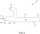
- the leading edge portion 56 of the BOAS segment has an elongated transition portion 56b extending from the leading edge 76 to the inner diameter flowpath surface 64.
- the elongated transition portion 56b which may have various configurations as hereinafter described, defines an optimized leading edge geometry that deviates away from a conventional leading edge geometry (see, e.g., FIGS. 5A through 5H ).
- the elongated transition portion 56b has an axial length (L) that is greater than a radial height (H), of up to one order of magnitude.
- the axial length of the elongated transition portion 56b is about three to about ten times the radial height of the elongated transition portion 56b.
- the axial length is defined as the length between a first tangency point 74 defined between the leading edge (face) 76 and the leading edge wall 56a and a second tangency point 78 defined between the leading edge wall 56a and the inner diameter flowpath surface 64.
- the radial height is defined as the radial distance between the inner diameter flowpath surface 64 and the first tangency point 74.
- the elongated transition portion 56b is configured as an ellipse.
- the ellipse may have an elliptical factor of greater than about 3, wherein the elliptical factor is defined as a length of a major axis divided by the length of a minor axis.
- the elongated transition portion is configured with the ellipse ( FIG. 5G ) or, in arrangements outside the scope of the present invention, with a chamfer in combination with a radius ( FIG. 5H ). A degree of the chamfer is less than about 18 degrees.
- the shape of the elongated transition portion (the ellipse) in FIG. 5G is the same as the shape of the elongated transition portion in FIG. 5D .
- the leading edge portion (more particularly, the elongated transition portion) of the BOAS segment (and other gas turbine engine components) has a geometry such that over an operational temperature range, thermal and/or mechanical deflections of a non-rotating structure (e.g., the upstream stator vane 72 depicted in FIG. 2 ) upstream of the BOAS array relative to thermal and/or mechanical deflections of the BOAS array cause relative movement of the non-rotating structure and the BOAS array to expose the leading edge portion of the BOAS to hot core flowpath air.
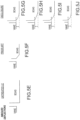
- the BOAS array may be radially deflected outboard of the upstream non-rotating structure as shown in FIGS. 5A through 5D (a "waterfall condition") or radially deflected inboard of the upstream non-rotating structure as shown in FIGS. 5E through 5J (a "dam condition").
- FIG. 5A depicts a BOAS segment/array with an untreated (i.e., not configured in accordance with various embodiments) leading edge portion.
- the leading edge portion of the BOAS segment/array in each of FIGS. 5A, 5B, and 5C is fully exposed to hot core flowpath air ("hot gas flow").
- 5D has the elongated transition portion configured as the ellipse in accordance with the present invention, such that the hot core flowpath air is transitioned from the upstream vane to the BOAS array with a reduced incidence angle (relative to the conventional or untreated leading edge geometry) accommodating an increased range of relative radial deflection.
- FIGS. 5E through 5H depict a BOAS segment/array with an untreated (i.e., not configured in accordance with various embodiments) leading edge portion.
- FIGS. 5F depicts a BOAS segment/array with a conventional chamfered transition between the leading edge wall and the inner flowstream path.
- the BOAS segment/array in FIG. 5G has the elongated transition portion configured as an ellipse in accordance with the present invention, so as to permit more deflection of the hot core flowpath air off the leading edge portion of the BOAS segment/array relative to an untreated or conventional BOAS segment/array ( FIGS. 5A-5C and 5E-5F ).
- the BOAS segment/array in FIG. 5G has the elongated transition portion configured as an ellipse in accordance with the present invention, so as to permit more deflection of the hot core flowpath air off the leading edge portion of the BOAS segment/array relative to an untreated or conventional BOAS segment/array ( FIGS. 5A-5C and 5E-5F ).
- FIG. 5H has an elongated transition portion configured as a chamfer with a blended radius, so as to also permit more deflection of the hot core flowpath air off the leading edge portion of the BOAS segment/array relative to an untreated or conventional BOAS segment/array ( FIGS. 5A-5C and 5E-5F ).
- the elongated transition portion configured as a chamfer with blended radii as depicted in FIG. 5H is also easier to make and inspect relative to other transitions.
- FIG. 5I is a schematic view of the leading edge portion of an exemplary BOAS segment outside the scope of the present invention illustrating that a transition of the elongated transition portion to the leading edge (face) of the BOAS segment may produce a corner rather than a tangent as in FIGS. 5D and 5G-5H.
- FIG. 5J is a schematic view of the leading edge portion of an exemplary BOAS segment outside the scope of the present invention illustrating an elongated transition portion comprising a short chamfer between
- the BOAS segment 50 is subjected to different thermal loads and environmental conditions (i.e., the thermal environment surrounding each turbine or compressor stage varies during operation).
- the thermal and/or mechanical deflections of the non-rotating structure adjacent to the BOAS segment array and the thermal and/or mechanical deflections of the BOAS segment array may be such that relative movement exposes the leading edge portion to hot core flowpath air.
- the leading edge portion is configured such that the hot core flowpath air is transitioned from the upstream non-rotating structure (e.g., the upstream stator vane) to the BOAS array with a reduced incidence angle that accommodates an increased range of relative radial deflections.
- the variation in the radial clearance between the stationary vane and the adjacent BOAS is a result of how the outer stator vane platform 65 and the engine case structure 44 react different to the varying thermal environment.
- a transition of the outer stator vane platform 65 to the leading edge of the BOAS is defined to yield a smooth core flowpath at steady state conditions for maximum efficiency, typically at cruise conditions.
- relative motion or shifts between the T1 stator vane and the T1 BOAS segment due to the varying thermal environment can result in the BOAS leading edge portion moving radially outboard of the outer stator vane platform 65 (outer diameter platform) of the T1 stator vane, creating an outward step in the hot core flowpath from the outer stator vane platform 65 and BOAS (see, e.g., FIGS.
- the elongated transition portion 56b may improve gas flow transition across the leading edge wall 56a, and may prevent a stagnation region at the leading edge portion 56. More particularly, various embodiments permit the transition from the upstream stator vane to the leading edge of the BOAS to be smoother and the leading edge portion less sensitive to being projected into the hot core flowpath air as a result of the relative movement/shifting of the BOAS segment and the surrounding static structure (e.g., the upstream stator vanes). As a result, various embodiments prolong BOAS life and/or tend to minimize cooling flow requirements for the BOAS segment/array, thereby maximizing turbine efficiency.
- the proximate flowpath surface for the BOAS leading edge 76 of the main body 54 of BOAS segment 50 is the inner diameter flowpath surface 64.
- stator vane 72 has an elongated transition portion 65b on outer stator vane platform 65 that transitions from a static combustor panel (not shown) at an outer platform leading edge 77 to the proximate flowpath surface 65c, the boundary between outer stator vane platform 65 and an airfoil 71 of stator vane 72.
- inner stator vane platform 63 includes an elongated transition portion 63b that extends from an inner platform leading edge 79 to a proximate flowpath surface 63c, the boundary between the elongated transition portion 63b and the airfoil 71 of stator vane 72.
- the "proximate flowpath surface" may be an inner flowpath surface or an outer flowpath surface.
- first turbine stage of a HPT is depicted in FIG. 2
- various embodiments may be utilized for static gas turbine engine components in any turbine stage of the HPT or low-pressure turbine (LPT) (i.e., first turbine) and in any compressor stage of the high-pressure compressor (HPC) (i.e., second compressor) or the low-pressure compressor (LPC) (i.e., first compressor).
- LPT low-pressure turbine
- HPC high-pressure compressor
- LPC low-pressure compressor
- mechanical and thermal deflections of a non-rotating structure adjacent to a gas turbine engine component may be such that relative movement exposes a leading edge portion of the gas turbine engine component to hot core flowpath air.
- the leading edge portion of the gas turbine engine component may be configured with the optimized leading edge geometry in accordance with various embodiments such that the hot core flowpath air is transitioned from the upstream non-rotating structure to the gas turbine engine component with reduced incidence angle that accommodates an increased range of relative radial deflections.
- Other exemplary gas turbine engine components that may benefit from various embodiments include, but are not limited to, combustor panels, vane platforms, BOAS, Mid-turbine frames, Transition ducts, etc.
- references to "various embodiments”, “one embodiment”, “an embodiment”, “an example embodiment”, etc. indicate that the embodiment described may include a particular feature, structure, or characteristic, but every embodiment may not necessarily include the particular feature, structure, or characteristic. Moreover, such phrases are not necessarily referring to the same embodiment.
Landscapes
- Engineering & Computer Science (AREA)
- Mechanical Engineering (AREA)
- General Engineering & Computer Science (AREA)
- Physics & Mathematics (AREA)
- Fluid Mechanics (AREA)
- Turbine Rotor Nozzle Sealing (AREA)
- Structures Of Non-Positive Displacement Pumps (AREA)
- Supercharger (AREA)
Claims (7)
- Gasturbinentriebwerkskomponente, umfassend einen Hauptkörper (54), der eine Vorderkante (76) und eine Vorderkantenwand (56a) aufweist, die einen länglichen Übergangsabschnitt (56b) beinhaltet, der sich zwischen der Vorderkante (76) und einer Oberfläche des Strömungspfadinnendurchmessers (64) des Hauptkörpers (54) erstreckt, wobei der längliche Übergangsabschnitt (56b) eine axiale Länge (L) und eine radiale Höhe aufweist und die axiale Länge (L) größer ist als die radiale Höhe, wobei der längliche Übergangsabschnitt (56b) als Ellipse konfiguriert ist, dadurch gekennzeichnet, dass:
die axiale Länge (L) von einem ersten zwischen der Vorderkante (76) und der Vorderkantenwand (56a) definierten Tangentialpunkt (74) zu einem zweiten zwischen der Vorderkantenwand (56a) und der Oberfläche des Strömungspfadinnendurchmessers (64) definierten Tangentialpunkt (78) definiert ist. - Gasturbinentriebwerkskomponente nach Anspruch 1, wobei eine statische Konstruktion (36) derart konfiguriert ist, dass sie benachbart zu und stromaufwärts von der Gasturbinentriebwerkskomponente in einem Gasturbinentriebwerk (20) angeordnet ist und jede der statischen Konstruktion (36) und der Gasturbinentriebwerkskomponente dazu konfiguriert ist, sich aufgrund thermischer oder mechanischer Auslenkungen relativ zueinander zu bewegen, sodass heiße Luft in einem Kernströmungspfad mit einem verringerten Einfallswinkel, der einen größeren Bereich relativer radialer Auslenkungen aufnimmt, von der stromaufwärts gelegenen statischen Konstruktion (36) zu der Gasturbinentriebwerkskomponente überführt wird.
- Gasturbinentriebwerkskomponente nach Anspruch 1 oder 2, wobei die axiale Länge um bis zu eine Größenordnung größer ist als die radiale Höhe.
- Gasturbinentriebwerkskomponente nach einem vorhergehenden Anspruch, wobei die Gasturbinenkomponente ein Segment mit äußerer Schaufelluftdichtung (blade outer air seal - BOAS) (50) umfasst.
- Gasturbinentriebwerkskomponente nach Anspruch 4, wobei das BOAS-Segment (50) dazu konfiguriert ist, einer Rotorschaufel (70) zugewandt zu sein, um einen radialen Spitzenabstand (53) zwischen der Rotorschaufel (70) und dem BOAS-Segment (50) zu definieren, und der radiale Spitzenabstand (53) zwischen der Oberfläche des Strömungspfadinnendurchmessers (64) des BOAS-Segments (50) und einer Spitze der Rotorschaufel (70) liegt.
- Gasturbinentriebwerkskomponente nach einem der vorhergehenden Ansprüche, wobei die axiale Länge des länglichen Übergangsabschnitts (56b) etwa das Drei- bis etwa Zehnfache der radialen Höhe des länglichen Übergangsabschnitts (56b) beträgt.
- Gasturbinentriebwerkskomponente nach einem der vorhergehenden Ansprüche, wobei die Ellipse einen Ellipsenfaktor von größer als etwa 3 aufweist, wobei der Ellipsenfaktor als Länge einer Hauptachse dividiert durch die Länge einer Nebenachse definiert ist.
Priority Applications (1)
| Application Number | Priority Date | Filing Date | Title |
|---|---|---|---|
| EP24200912.4A EP4459109A3 (de) | 2016-01-15 | 2016-11-15 | Gasturbinenmotorkomponente mit optimierter vorderkantengeometrie |
Applications Claiming Priority (1)
| Application Number | Priority Date | Filing Date | Title |
|---|---|---|---|
| US14/997,323 US10138748B2 (en) | 2016-01-15 | 2016-01-15 | Gas turbine engine components with optimized leading edge geometry |
Related Child Applications (1)
| Application Number | Title | Priority Date | Filing Date |
|---|---|---|---|
| EP24200912.4A Division EP4459109A3 (de) | 2016-01-15 | 2016-11-15 | Gasturbinenmotorkomponente mit optimierter vorderkantengeometrie |
Publications (2)
| Publication Number | Publication Date |
|---|---|
| EP3192969A1 EP3192969A1 (de) | 2017-07-19 |
| EP3192969B1 true EP3192969B1 (de) | 2024-09-18 |
Family
ID=57321206
Family Applications (2)
| Application Number | Title | Priority Date | Filing Date |
|---|---|---|---|
| EP16198828.2A Active EP3192969B1 (de) | 2016-01-15 | 2016-11-15 | Gasturbinentriebwerk komponente mit optimierter geometrie an der leitkante |
| EP24200912.4A Pending EP4459109A3 (de) | 2016-01-15 | 2016-11-15 | Gasturbinenmotorkomponente mit optimierter vorderkantengeometrie |
Family Applications After (1)
| Application Number | Title | Priority Date | Filing Date |
|---|---|---|---|
| EP24200912.4A Pending EP4459109A3 (de) | 2016-01-15 | 2016-11-15 | Gasturbinenmotorkomponente mit optimierter vorderkantengeometrie |
Country Status (2)
| Country | Link |
|---|---|
| US (1) | US10138748B2 (de) |
| EP (2) | EP3192969B1 (de) |
Families Citing this family (3)
| Publication number | Priority date | Publication date | Assignee | Title |
|---|---|---|---|---|
| US10648407B2 (en) * | 2018-09-05 | 2020-05-12 | United Technologies Corporation | CMC boas cooling air flow guide |
| US11131206B2 (en) * | 2018-11-08 | 2021-09-28 | Raytheon Technologies Corporation | Substrate edge configurations for ceramic coatings |
| EP4343119A1 (de) * | 2022-09-23 | 2024-03-27 | Siemens Energy Global GmbH & Co. KG | Ringsegment für gasturbinentriebwerk |
Citations (1)
| Publication number | Priority date | Publication date | Assignee | Title |
|---|---|---|---|---|
| EP3156613A2 (de) * | 2015-10-16 | 2017-04-19 | United Technologies Corporation | Aussenluftdichtung für eine turbinenschaufel |
Family Cites Families (4)
| Publication number | Priority date | Publication date | Assignee | Title |
|---|---|---|---|---|
| US6398158B1 (en) * | 2001-06-22 | 2002-06-04 | The United States Of America As Represented By The Secretary Of The Navy | High altitude low flying platform hull |
| US7553128B2 (en) | 2006-10-12 | 2009-06-30 | United Technologies Corporation | Blade outer air seals |
| US8251637B2 (en) * | 2008-05-16 | 2012-08-28 | General Electric Company | Systems and methods for modifying modal vibration associated with a turbine |
| US9896955B2 (en) | 2015-04-13 | 2018-02-20 | United Technologies Corporation | Static axial brush seal with dual bristle packs |
-
2016
- 2016-01-15 US US14/997,323 patent/US10138748B2/en active Active
- 2016-11-15 EP EP16198828.2A patent/EP3192969B1/de active Active
- 2016-11-15 EP EP24200912.4A patent/EP4459109A3/de active Pending
Patent Citations (1)
| Publication number | Priority date | Publication date | Assignee | Title |
|---|---|---|---|---|
| EP3156613A2 (de) * | 2015-10-16 | 2017-04-19 | United Technologies Corporation | Aussenluftdichtung für eine turbinenschaufel |
Also Published As
| Publication number | Publication date |
|---|---|
| US20170204735A1 (en) | 2017-07-20 |
| EP4459109A3 (de) | 2025-04-23 |
| EP3192969A1 (de) | 2017-07-19 |
| US10138748B2 (en) | 2018-11-27 |
| EP4459109A2 (de) | 2024-11-06 |
Similar Documents
| Publication | Publication Date | Title |
|---|---|---|
| EP3543469B1 (de) | Äussere laufschaufelluftdichtungsanordnung mit federdichtung | |
| EP3734018B1 (de) | Dichtung für ein gasturbinentriebwerks-bauteil und zugehöriges verfahren | |
| EP3663528B1 (de) | Gasturbinentriebwerkbogensegmente mit gewölbten wänden | |
| EP2964934B1 (de) | Gasturbinenmotorkomponente mit einem federdichtungsschlitz von variabler breite | |
| US11661865B2 (en) | Gas turbine engine component | |
| EP3064711B1 (de) | Bauteil für ein gasturbinentriebwerk, zugehöriges gasturbinentriebwerk und verfahren zur formung einer schaufel | |
| EP3587740B1 (de) | Dichtungsanordnung für ein gasturbinentriebwerk und montageverfahren | |
| EP2877709B1 (de) | Äussere laufschaufelluftdichtung für einen gasturbinenmotor | |
| EP3093445B1 (de) | Gasturbinen-leitschaufel und herstellungsverfahren | |
| EP3112606B1 (de) | Dichtung für einen gasturbinenmotor | |
| EP3192969B1 (de) | Gasturbinentriebwerk komponente mit optimierter geometrie an der leitkante | |
| EP3708773A2 (de) | Dichtung für einen gasturbinenmotor | |
| EP3467260B1 (de) | Turbinentlaufschaufel mit gekrümmter schaufelspitze | |
| EP3192976B1 (de) | Gasturbinentriebwerkskomponente, zugehörige äussere laufschaufelluftdichtung und gasturbinentriebwerk | |
| US20170268365A1 (en) | Seal arc segment with anti-rotation feature | |
| EP3470627B1 (de) | Gasturbinenmotorschaufel | |
| EP3156613B1 (de) | Aussenluftdichtung für eine schaufel | |
| WO2014035621A1 (en) | Blade outer air seal | |
| EP3495621B1 (de) | Stützring für ein gasturbinentriebwerk |
Legal Events
| Date | Code | Title | Description |
|---|---|---|---|
| PUAI | Public reference made under article 153(3) epc to a published international application that has entered the european phase |
Free format text: ORIGINAL CODE: 0009012 |
|
| STAA | Information on the status of an ep patent application or granted ep patent |
Free format text: STATUS: THE APPLICATION HAS BEEN PUBLISHED |
|
| AK | Designated contracting states |
Kind code of ref document: A1 Designated state(s): AL AT BE BG CH CY CZ DE DK EE ES FI FR GB GR HR HU IE IS IT LI LT LU LV MC MK MT NL NO PL PT RO RS SE SI SK SM TR |
|
| AX | Request for extension of the european patent |
Extension state: BA ME |
|
| RIN1 | Information on inventor provided before grant (corrected) |
Inventor name: LUTJEN, PAUL M. Inventor name: JAROCHYM, CHRISTOPHER M. Inventor name: BLANEY, KEN F. Inventor name: SWIFT, ANTHONY B. Inventor name: TATMAN, NEIL L. Inventor name: PRAISNER, THOMAS J. |
|
| STAA | Information on the status of an ep patent application or granted ep patent |
Free format text: STATUS: REQUEST FOR EXAMINATION WAS MADE |
|
| 17P | Request for examination filed |
Effective date: 20180119 |
|
| RBV | Designated contracting states (corrected) |
Designated state(s): AL AT BE BG CH CY CZ DE DK EE ES FI FR GB GR HR HU IE IS IT LI LT LU LV MC MK MT NL NO PL PT RO RS SE SI SK SM TR |
|
| RAP1 | Party data changed (applicant data changed or rights of an application transferred) |
Owner name: RAYTHEON TECHNOLOGIES CORPORATION |
|
| STAA | Information on the status of an ep patent application or granted ep patent |
Free format text: STATUS: EXAMINATION IS IN PROGRESS |
|
| 17Q | First examination report despatched |
Effective date: 20210520 |
|
| RAP3 | Party data changed (applicant data changed or rights of an application transferred) |
Owner name: RTX CORPORATION |
|
| GRAP | Despatch of communication of intention to grant a patent |
Free format text: ORIGINAL CODE: EPIDOSNIGR1 |
|
| STAA | Information on the status of an ep patent application or granted ep patent |
Free format text: STATUS: GRANT OF PATENT IS INTENDED |
|
| INTG | Intention to grant announced |
Effective date: 20240417 |
|
| GRAS | Grant fee paid |
Free format text: ORIGINAL CODE: EPIDOSNIGR3 |
|
| GRAA | (expected) grant |
Free format text: ORIGINAL CODE: 0009210 |
|
| STAA | Information on the status of an ep patent application or granted ep patent |
Free format text: STATUS: THE PATENT HAS BEEN GRANTED |
|
| AK | Designated contracting states |
Kind code of ref document: B1 Designated state(s): AL AT BE BG CH CY CZ DE DK EE ES FI FR GB GR HR HU IE IS IT LI LT LU LV MC MK MT NL NO PL PT RO RS SE SI SK SM TR |
|
| REG | Reference to a national code |
Ref country code: GB Ref legal event code: FG4D |
|
| REG | Reference to a national code |
Ref country code: CH Ref legal event code: EP |
|
| REG | Reference to a national code |
Ref country code: DE Ref legal event code: R096 Ref document number: 602016089433 Country of ref document: DE |
|
| REG | Reference to a national code |
Ref country code: IE Ref legal event code: FG4D |
|
| REG | Reference to a national code |
Ref country code: LT Ref legal event code: MG9D |
|
| PG25 | Lapsed in a contracting state [announced via postgrant information from national office to epo] |
Ref country code: NO Free format text: LAPSE BECAUSE OF FAILURE TO SUBMIT A TRANSLATION OF THE DESCRIPTION OR TO PAY THE FEE WITHIN THE PRESCRIBED TIME-LIMIT Effective date: 20241218 |
|
| PG25 | Lapsed in a contracting state [announced via postgrant information from national office to epo] |
Ref country code: GR Free format text: LAPSE BECAUSE OF FAILURE TO SUBMIT A TRANSLATION OF THE DESCRIPTION OR TO PAY THE FEE WITHIN THE PRESCRIBED TIME-LIMIT Effective date: 20241219 Ref country code: FI Free format text: LAPSE BECAUSE OF FAILURE TO SUBMIT A TRANSLATION OF THE DESCRIPTION OR TO PAY THE FEE WITHIN THE PRESCRIBED TIME-LIMIT Effective date: 20240918 |
|
| PG25 | Lapsed in a contracting state [announced via postgrant information from national office to epo] |
Ref country code: BG Free format text: LAPSE BECAUSE OF FAILURE TO SUBMIT A TRANSLATION OF THE DESCRIPTION OR TO PAY THE FEE WITHIN THE PRESCRIBED TIME-LIMIT Effective date: 20240918 |
|
| PG25 | Lapsed in a contracting state [announced via postgrant information from national office to epo] |
Ref country code: LV Free format text: LAPSE BECAUSE OF FAILURE TO SUBMIT A TRANSLATION OF THE DESCRIPTION OR TO PAY THE FEE WITHIN THE PRESCRIBED TIME-LIMIT Effective date: 20240918 |
|
| PG25 | Lapsed in a contracting state [announced via postgrant information from national office to epo] |
Ref country code: HR Free format text: LAPSE BECAUSE OF FAILURE TO SUBMIT A TRANSLATION OF THE DESCRIPTION OR TO PAY THE FEE WITHIN THE PRESCRIBED TIME-LIMIT Effective date: 20240918 |
|
| REG | Reference to a national code |
Ref country code: NL Ref legal event code: MP Effective date: 20240918 |
|
| PG25 | Lapsed in a contracting state [announced via postgrant information from national office to epo] |
Ref country code: RS Free format text: LAPSE BECAUSE OF FAILURE TO SUBMIT A TRANSLATION OF THE DESCRIPTION OR TO PAY THE FEE WITHIN THE PRESCRIBED TIME-LIMIT Effective date: 20241218 |
|
| PG25 | Lapsed in a contracting state [announced via postgrant information from national office to epo] |
Ref country code: RS Free format text: LAPSE BECAUSE OF FAILURE TO SUBMIT A TRANSLATION OF THE DESCRIPTION OR TO PAY THE FEE WITHIN THE PRESCRIBED TIME-LIMIT Effective date: 20241218 Ref country code: NO Free format text: LAPSE BECAUSE OF FAILURE TO SUBMIT A TRANSLATION OF THE DESCRIPTION OR TO PAY THE FEE WITHIN THE PRESCRIBED TIME-LIMIT Effective date: 20241218 Ref country code: LV Free format text: LAPSE BECAUSE OF FAILURE TO SUBMIT A TRANSLATION OF THE DESCRIPTION OR TO PAY THE FEE WITHIN THE PRESCRIBED TIME-LIMIT Effective date: 20240918 Ref country code: HR Free format text: LAPSE BECAUSE OF FAILURE TO SUBMIT A TRANSLATION OF THE DESCRIPTION OR TO PAY THE FEE WITHIN THE PRESCRIBED TIME-LIMIT Effective date: 20240918 Ref country code: GR Free format text: LAPSE BECAUSE OF FAILURE TO SUBMIT A TRANSLATION OF THE DESCRIPTION OR TO PAY THE FEE WITHIN THE PRESCRIBED TIME-LIMIT Effective date: 20241219 Ref country code: FI Free format text: LAPSE BECAUSE OF FAILURE TO SUBMIT A TRANSLATION OF THE DESCRIPTION OR TO PAY THE FEE WITHIN THE PRESCRIBED TIME-LIMIT Effective date: 20240918 Ref country code: BG Free format text: LAPSE BECAUSE OF FAILURE TO SUBMIT A TRANSLATION OF THE DESCRIPTION OR TO PAY THE FEE WITHIN THE PRESCRIBED TIME-LIMIT Effective date: 20240918 |
|
| REG | Reference to a national code |
Ref country code: AT Ref legal event code: MK05 Ref document number: 1724841 Country of ref document: AT Kind code of ref document: T Effective date: 20240918 |
|
| PG25 | Lapsed in a contracting state [announced via postgrant information from national office to epo] |
Ref country code: NL Free format text: LAPSE BECAUSE OF FAILURE TO SUBMIT A TRANSLATION OF THE DESCRIPTION OR TO PAY THE FEE WITHIN THE PRESCRIBED TIME-LIMIT Effective date: 20240918 |
|
| PG25 | Lapsed in a contracting state [announced via postgrant information from national office to epo] |
Ref country code: PT Free format text: LAPSE BECAUSE OF FAILURE TO SUBMIT A TRANSLATION OF THE DESCRIPTION OR TO PAY THE FEE WITHIN THE PRESCRIBED TIME-LIMIT Effective date: 20250120 Ref country code: IS Free format text: LAPSE BECAUSE OF FAILURE TO SUBMIT A TRANSLATION OF THE DESCRIPTION OR TO PAY THE FEE WITHIN THE PRESCRIBED TIME-LIMIT Effective date: 20250118 |
|
| PG25 | Lapsed in a contracting state [announced via postgrant information from national office to epo] |
Ref country code: SM Free format text: LAPSE BECAUSE OF FAILURE TO SUBMIT A TRANSLATION OF THE DESCRIPTION OR TO PAY THE FEE WITHIN THE PRESCRIBED TIME-LIMIT Effective date: 20240918 Ref country code: RO Free format text: LAPSE BECAUSE OF FAILURE TO SUBMIT A TRANSLATION OF THE DESCRIPTION OR TO PAY THE FEE WITHIN THE PRESCRIBED TIME-LIMIT Effective date: 20240918 |
|
| PG25 | Lapsed in a contracting state [announced via postgrant information from national office to epo] |
Ref country code: ES Free format text: LAPSE BECAUSE OF FAILURE TO SUBMIT A TRANSLATION OF THE DESCRIPTION OR TO PAY THE FEE WITHIN THE PRESCRIBED TIME-LIMIT Effective date: 20240918 |
|
| PG25 | Lapsed in a contracting state [announced via postgrant information from national office to epo] |
Ref country code: AT Free format text: LAPSE BECAUSE OF FAILURE TO SUBMIT A TRANSLATION OF THE DESCRIPTION OR TO PAY THE FEE WITHIN THE PRESCRIBED TIME-LIMIT Effective date: 20240918 Ref country code: EE Free format text: LAPSE BECAUSE OF FAILURE TO SUBMIT A TRANSLATION OF THE DESCRIPTION OR TO PAY THE FEE WITHIN THE PRESCRIBED TIME-LIMIT Effective date: 20240918 |
|
| PG25 | Lapsed in a contracting state [announced via postgrant information from national office to epo] |
Ref country code: PL Free format text: LAPSE BECAUSE OF FAILURE TO SUBMIT A TRANSLATION OF THE DESCRIPTION OR TO PAY THE FEE WITHIN THE PRESCRIBED TIME-LIMIT Effective date: 20240918 Ref country code: CZ Free format text: LAPSE BECAUSE OF FAILURE TO SUBMIT A TRANSLATION OF THE DESCRIPTION OR TO PAY THE FEE WITHIN THE PRESCRIBED TIME-LIMIT Effective date: 20240918 |
|
| PG25 | Lapsed in a contracting state [announced via postgrant information from national office to epo] |
Ref country code: SK Free format text: LAPSE BECAUSE OF FAILURE TO SUBMIT A TRANSLATION OF THE DESCRIPTION OR TO PAY THE FEE WITHIN THE PRESCRIBED TIME-LIMIT Effective date: 20240918 Ref country code: IT Free format text: LAPSE BECAUSE OF FAILURE TO SUBMIT A TRANSLATION OF THE DESCRIPTION OR TO PAY THE FEE WITHIN THE PRESCRIBED TIME-LIMIT Effective date: 20240918 |
|
| REG | Reference to a national code |
Ref country code: DE Ref legal event code: R097 Ref document number: 602016089433 Country of ref document: DE |
|
| REG | Reference to a national code |
Ref country code: CH Ref legal event code: PL |
|
| PG25 | Lapsed in a contracting state [announced via postgrant information from national office to epo] |
Ref country code: MC Free format text: LAPSE BECAUSE OF FAILURE TO SUBMIT A TRANSLATION OF THE DESCRIPTION OR TO PAY THE FEE WITHIN THE PRESCRIBED TIME-LIMIT Effective date: 20240918 |
|
| PG25 | Lapsed in a contracting state [announced via postgrant information from national office to epo] |
Ref country code: DK Free format text: LAPSE BECAUSE OF FAILURE TO SUBMIT A TRANSLATION OF THE DESCRIPTION OR TO PAY THE FEE WITHIN THE PRESCRIBED TIME-LIMIT Effective date: 20240918 |
|
| PG25 | Lapsed in a contracting state [announced via postgrant information from national office to epo] |
Ref country code: LU Free format text: LAPSE BECAUSE OF NON-PAYMENT OF DUE FEES Effective date: 20241115 |
|
| REG | Reference to a national code |
Ref country code: CH Ref legal event code: PL |
|
| PG25 | Lapsed in a contracting state [announced via postgrant information from national office to epo] |
Ref country code: CH Free format text: LAPSE BECAUSE OF NON-PAYMENT OF DUE FEES Effective date: 20241130 |
|
| PLBE | No opposition filed within time limit |
Free format text: ORIGINAL CODE: 0009261 |
|
| STAA | Information on the status of an ep patent application or granted ep patent |
Free format text: STATUS: NO OPPOSITION FILED WITHIN TIME LIMIT |
|
| 26N | No opposition filed |
Effective date: 20250619 |
|
| REG | Reference to a national code |
Ref country code: BE Ref legal event code: MM Effective date: 20241130 |
|
| PG25 | Lapsed in a contracting state [announced via postgrant information from national office to epo] |
Ref country code: SE Free format text: LAPSE BECAUSE OF FAILURE TO SUBMIT A TRANSLATION OF THE DESCRIPTION OR TO PAY THE FEE WITHIN THE PRESCRIBED TIME-LIMIT Effective date: 20240918 |
|
| PG25 | Lapsed in a contracting state [announced via postgrant information from national office to epo] |
Ref country code: BE Free format text: LAPSE BECAUSE OF NON-PAYMENT OF DUE FEES Effective date: 20241130 |
|
| PG25 | Lapsed in a contracting state [announced via postgrant information from national office to epo] |
Ref country code: IE Free format text: LAPSE BECAUSE OF NON-PAYMENT OF DUE FEES Effective date: 20241115 |
|
| PGFP | Annual fee paid to national office [announced via postgrant information from national office to epo] |
Ref country code: DE Payment date: 20251022 Year of fee payment: 10 |
|
| PGFP | Annual fee paid to national office [announced via postgrant information from national office to epo] |
Ref country code: GB Payment date: 20251023 Year of fee payment: 10 |
|
| PGFP | Annual fee paid to national office [announced via postgrant information from national office to epo] |
Ref country code: FR Payment date: 20251022 Year of fee payment: 10 |
|
| PG25 | Lapsed in a contracting state [announced via postgrant information from national office to epo] |
Ref country code: HU Free format text: LAPSE BECAUSE OF FAILURE TO SUBMIT A TRANSLATION OF THE DESCRIPTION OR TO PAY THE FEE WITHIN THE PRESCRIBED TIME-LIMIT; INVALID AB INITIO Effective date: 20161115 |
|
| PG25 | Lapsed in a contracting state [announced via postgrant information from national office to epo] |
Ref country code: CY Free format text: LAPSE BECAUSE OF FAILURE TO SUBMIT A TRANSLATION OF THE DESCRIPTION OR TO PAY THE FEE WITHIN THE PRESCRIBED TIME-LIMIT; INVALID AB INITIO Effective date: 20161115 |