EP3193141A1 - Capteur de position d'actionneur électromécanique - Google Patents
Capteur de position d'actionneur électromécanique Download PDFInfo
- Publication number
- EP3193141A1 EP3193141A1 EP16198514.8A EP16198514A EP3193141A1 EP 3193141 A1 EP3193141 A1 EP 3193141A1 EP 16198514 A EP16198514 A EP 16198514A EP 3193141 A1 EP3193141 A1 EP 3193141A1
- Authority
- EP
- European Patent Office
- Prior art keywords
- arm
- component
- position sensor
- relative
- output arm
- Prior art date
- Legal status (The legal status is an assumption and is not a legal conclusion. Google has not performed a legal analysis and makes no representation as to the accuracy of the status listed.)
- Granted
Links
Images


Classifications
-
- G—PHYSICS
- G01—MEASURING; TESTING
- G01D—MEASURING NOT SPECIALLY ADAPTED FOR A SPECIFIC VARIABLE; ARRANGEMENTS FOR MEASURING TWO OR MORE VARIABLES NOT COVERED IN A SINGLE OTHER SUBCLASS; TARIFF METERING APPARATUS; MEASURING OR TESTING NOT OTHERWISE PROVIDED FOR
- G01D5/00—Mechanical means for transferring the output of a sensing member; Means for converting the output of a sensing member to another variable where the form or nature of the sensing member does not constrain the means for converting; Transducers not specially adapted for a specific variable
- G01D5/12—Mechanical means for transferring the output of a sensing member; Means for converting the output of a sensing member to another variable where the form or nature of the sensing member does not constrain the means for converting; Transducers not specially adapted for a specific variable using electric or magnetic means
- G01D5/14—Mechanical means for transferring the output of a sensing member; Means for converting the output of a sensing member to another variable where the form or nature of the sensing member does not constrain the means for converting; Transducers not specially adapted for a specific variable using electric or magnetic means influencing the magnitude of a current or voltage
- G01D5/142—Mechanical means for transferring the output of a sensing member; Means for converting the output of a sensing member to another variable where the form or nature of the sensing member does not constrain the means for converting; Transducers not specially adapted for a specific variable using electric or magnetic means influencing the magnitude of a current or voltage using Hall-effect devices
- G01D5/145—Mechanical means for transferring the output of a sensing member; Means for converting the output of a sensing member to another variable where the form or nature of the sensing member does not constrain the means for converting; Transducers not specially adapted for a specific variable using electric or magnetic means influencing the magnitude of a current or voltage using Hall-effect devices influenced by the relative movement between the Hall device and magnetic fields
-
- G—PHYSICS
- G01—MEASURING; TESTING
- G01D—MEASURING NOT SPECIALLY ADAPTED FOR A SPECIFIC VARIABLE; ARRANGEMENTS FOR MEASURING TWO OR MORE VARIABLES NOT COVERED IN A SINGLE OTHER SUBCLASS; TARIFF METERING APPARATUS; MEASURING OR TESTING NOT OTHERWISE PROVIDED FOR
- G01D5/00—Mechanical means for transferring the output of a sensing member; Means for converting the output of a sensing member to another variable where the form or nature of the sensing member does not constrain the means for converting; Transducers not specially adapted for a specific variable
- G01D5/12—Mechanical means for transferring the output of a sensing member; Means for converting the output of a sensing member to another variable where the form or nature of the sensing member does not constrain the means for converting; Transducers not specially adapted for a specific variable using electric or magnetic means
- G01D5/14—Mechanical means for transferring the output of a sensing member; Means for converting the output of a sensing member to another variable where the form or nature of the sensing member does not constrain the means for converting; Transducers not specially adapted for a specific variable using electric or magnetic means influencing the magnitude of a current or voltage
- G01D5/142—Mechanical means for transferring the output of a sensing member; Means for converting the output of a sensing member to another variable where the form or nature of the sensing member does not constrain the means for converting; Transducers not specially adapted for a specific variable using electric or magnetic means influencing the magnitude of a current or voltage using Hall-effect devices
- G01D5/147—Mechanical means for transferring the output of a sensing member; Means for converting the output of a sensing member to another variable where the form or nature of the sensing member does not constrain the means for converting; Transducers not specially adapted for a specific variable using electric or magnetic means influencing the magnitude of a current or voltage using Hall-effect devices influenced by the movement of a third element, the position of Hall device and the source of magnetic field being fixed in respect to each other
-
- G—PHYSICS
- G01—MEASURING; TESTING
- G01D—MEASURING NOT SPECIALLY ADAPTED FOR A SPECIFIC VARIABLE; ARRANGEMENTS FOR MEASURING TWO OR MORE VARIABLES NOT COVERED IN A SINGLE OTHER SUBCLASS; TARIFF METERING APPARATUS; MEASURING OR TESTING NOT OTHERWISE PROVIDED FOR
- G01D5/00—Mechanical means for transferring the output of a sensing member; Means for converting the output of a sensing member to another variable where the form or nature of the sensing member does not constrain the means for converting; Transducers not specially adapted for a specific variable
- G01D5/12—Mechanical means for transferring the output of a sensing member; Means for converting the output of a sensing member to another variable where the form or nature of the sensing member does not constrain the means for converting; Transducers not specially adapted for a specific variable using electric or magnetic means
- G01D5/14—Mechanical means for transferring the output of a sensing member; Means for converting the output of a sensing member to another variable where the form or nature of the sensing member does not constrain the means for converting; Transducers not specially adapted for a specific variable using electric or magnetic means influencing the magnitude of a current or voltage
- G01D5/20—Mechanical means for transferring the output of a sensing member; Means for converting the output of a sensing member to another variable where the form or nature of the sensing member does not constrain the means for converting; Transducers not specially adapted for a specific variable using electric or magnetic means influencing the magnitude of a current or voltage by varying inductance, e.g. by a movable armature
- G01D5/2006—Mechanical means for transferring the output of a sensing member; Means for converting the output of a sensing member to another variable where the form or nature of the sensing member does not constrain the means for converting; Transducers not specially adapted for a specific variable using electric or magnetic means influencing the magnitude of a current or voltage by varying inductance, e.g. by a movable armature by influencing the self-induction of one or more coils
- G01D5/2013—Mechanical means for transferring the output of a sensing member; Means for converting the output of a sensing member to another variable where the form or nature of the sensing member does not constrain the means for converting; Transducers not specially adapted for a specific variable using electric or magnetic means influencing the magnitude of a current or voltage by varying inductance, e.g. by a movable armature by influencing the self-induction of one or more coils by a movable ferromagnetic element, e.g. a core
-
- G—PHYSICS
- G01—MEASURING; TESTING
- G01D—MEASURING NOT SPECIALLY ADAPTED FOR A SPECIFIC VARIABLE; ARRANGEMENTS FOR MEASURING TWO OR MORE VARIABLES NOT COVERED IN A SINGLE OTHER SUBCLASS; TARIFF METERING APPARATUS; MEASURING OR TESTING NOT OTHERWISE PROVIDED FOR
- G01D2205/00—Indexing scheme relating to details of means for transferring or converting the output of a sensing member
- G01D2205/70—Position sensors comprising a moving target with particular shapes, e.g. of soft magnetic targets
- G01D2205/77—Specific profiles
-
- G—PHYSICS
- G01—MEASURING; TESTING
- G01D—MEASURING NOT SPECIALLY ADAPTED FOR A SPECIFIC VARIABLE; ARRANGEMENTS FOR MEASURING TWO OR MORE VARIABLES NOT COVERED IN A SINGLE OTHER SUBCLASS; TARIFF METERING APPARATUS; MEASURING OR TESTING NOT OTHERWISE PROVIDED FOR
- G01D2205/00—Indexing scheme relating to details of means for transferring or converting the output of a sensing member
- G01D2205/70—Position sensors comprising a moving target with particular shapes, e.g. of soft magnetic targets
- G01D2205/77—Specific profiles
- G01D2205/775—Tapered profiles
-
- G—PHYSICS
- G01—MEASURING; TESTING
- G01D—MEASURING NOT SPECIALLY ADAPTED FOR A SPECIFIC VARIABLE; ARRANGEMENTS FOR MEASURING TWO OR MORE VARIABLES NOT COVERED IN A SINGLE OTHER SUBCLASS; TARIFF METERING APPARATUS; MEASURING OR TESTING NOT OTHERWISE PROVIDED FOR
- G01D2205/00—Indexing scheme relating to details of means for transferring or converting the output of a sensing member
- G01D2205/70—Position sensors comprising a moving target with particular shapes, e.g. of soft magnetic targets
- G01D2205/77—Specific profiles
- G01D2205/776—Cam-shaped profiles
-
- G—PHYSICS
- G01—MEASURING; TESTING
- G01D—MEASURING NOT SPECIALLY ADAPTED FOR A SPECIFIC VARIABLE; ARRANGEMENTS FOR MEASURING TWO OR MORE VARIABLES NOT COVERED IN A SINGLE OTHER SUBCLASS; TARIFF METERING APPARATUS; MEASURING OR TESTING NOT OTHERWISE PROVIDED FOR
- G01D2205/00—Indexing scheme relating to details of means for transferring or converting the output of a sensing member
- G01D2205/80—Manufacturing details of magnetic targets for magnetic encoders
Definitions
- the subject matter disclosed herein relates to electromechanical actuators. More specifically, the present disclosure relates to position sensing of electromechanical actuators.
- Rotary actuators rotate an element about an axis, such as flight control surfaces, for example, flaps and ailerons.
- flight control surfaces for example, flaps and ailerons.
- wings of thinner cross-sections such that size and space available for placement of the actuator inside of the wing is limited.
- the trend has led to the use of a rotary actuator of a "hinge-line” design, wherein a rotational axis of the actuator is aligned with that of the flight control surface and the actuator acts as a hinge (hence the term "hinge-line").
- This trend also raises the need for such an actuator with a tighter cross-section to fit the available space.
- Such actuators often use position sensing apparatus to sense and track the actuator position. As the sizes of the actuators are reduced in response to the thin wing trend, the volume occupied by a conventional position sensor becomes a significant percentage of the total actuator volume and a significant percentage of the cost.
- Typical position sensing for electromechanical actuators tends to fall into two categories, rotary variable differential transformer (RVDT) and encoders. Whereas RVDTs provide absolute position determination on startup, they are relatively large and expensive. Encoders, while smaller and less expensive than RVDTs, require some motion at startup to determine the position.
- RVDT rotary variable differential transformer
- an electromechanical actuator includes a ground arm, an output arm rotatable about an axis of rotation relative to the ground arm and a position sensing arrangement to determine an angular position of the output arm relative to the ground arm.
- the position sensing arrangement includes a position sensor fixed at the ground arm.
- the position sensor is configured to sense magnetic reluctance.
- a sensed portion is located at the output arm proximate to the position sensor.
- the sensed portion includes a geometric variation in an output arm surface configured to vary a magnetic reluctance sensed at the position sensor as a function of angular position of the output arm relative to the ground arm.
- the geometric variation is a groove located at the output arm extending circumferentially about the axis of rotation.
- the groove progressively widens and/or deepens along its length.
- the groove is radially centered on the position sensor.
- the geometric variation is a pattern of holes in the output arm.
- the pattern of holes varies in one or more of hole diameter, hole depth or hole spacing.
- the position sensor includes a magnet fixed at the ground arm to generate a magnetic field, and a hall effect sensor to detect variation in the magnetic field as the output arm is rotated about the axis of rotation relative to the ground arm.
- the hall effect sensor is positioned between the magnet and the output arm.
- an output voltage of the hall effect sensor is indicative of the angular position of the output arm.
- a relative position sensing system for two components includes a position sensor fixed at a first component.
- the position sensor is configured to sense magnetic reluctance.
- a sensed portion is positioned at a second component proximate to the position sensor.
- the sensed portion includes a geometric variation in a second component surface configured to vary a magnetic reluctance sensed at the position sensor as a function of angular position of the second component relative to the first component.
- the geometric variation is a groove located at the second component extending circumferentially about the axis of rotation.
- the groove progressively widens and/or deepens along its length.
- the groove is radially centered on the position sensor.
- the geometric variation is a pattern of holes in the second component.
- the pattern of holes varies in one or more of hole diameter, hole depth or hole spacing.
- the position sensor includes a magnet fixed at the first component to generate a magnetic field and a hall effect sensor to detect variation in the magnetic field as the second component is rotated about the axis of rotation relative to the first component.
- the hall effect sensor is located between the magnet and the second component.
- an output voltage of the hall effect sensor is indicative of the angular position of the second component relative to the first component.
- a wing for an aircraft in yet another embodiment, includes a fixed portion of the wing, and a control surface portion of the wing.
- the control surface portion is movable relative to the fixed portion.
- An electromechanical actuator drives movement of the control surface portion relative to the fixed portion and includes a ground arm secured to the fixed portion and an output arm secured to the control surface portion and rotatable about an axis of rotation relative to the ground arm.
- a position sensing arrangement determines an angular position of the output arm relative to the ground arm and includes a position sensor fixed at the ground arm.
- the position sensor is configured to sense magnetic reluctance.
- a sensed portion is located at the output arm proximate to the position sensor.
- the sensed portion includes a geometric variation in an output arm surface configured to vary a magnetic reluctance sensed at the position sensor as a function of angular position of the output arm relative to the ground arm.
- the geometric variation is a groove located at the output arm extending circumferentially about the axis of rotation.
- the groove progressively widens and/or deepens along its length.
- the geometric variation is a pattern of holes in the output arm.
- the pattern of holes varies in one or more of hole diameter, hole depth or hole spacing.
- the position sensor includes a magnet fixed at the ground arm to generate a magnetic field and a hall effect sensor to detect variation in the magnetic field as the output arm is rotated about the axis of rotation relative to the ground arm.
- an output voltage of the hall effect sensor is indicative of the angular position of the output arm.
- a non-limiting exemplary embodiment of a wing of an aircraft is generally indicated at 10.
- the wing 10 is disclosed herein as being implemented with a fixed-wing aircraft, such as an airplane, it should be appreciated that the wing 10 can be implemented with any suitable type of aircraft in general, and fixed-wing or rotary-wing aircraft (such as a helicopter), in particular.
- the wing 10 is one of two substantially similar wings of a lift system of the aircraft (in contrast, a rotor blade would be one of a plurality of substantially similar rotor blades of a rotor system of a helicopter).
- the wing 10 defines a root portion (not shown) that extends to a tip portion (not shown) through an aileron portion, generally indicated at 14, which acts as a flight-control or output-control surface (such as a wing flap).
- the aileron portion 14 also defines, in turn, an axis of motion of rotation 16 and includes an aileron spar, generally indicated at 18.
- the wing 10 further defines first and second opposing surfaces 20, 22, a trailing edge 24, and an opposing leading edge 26 and includes a wing spar, generally indicated at 28.
- the wing 10 also includes a control system (not shown) that has an electromechanical hinge-line rotary actuator, generally indicated at 30, and a controller (not shown).
- the actuator 30 defines the axis of rotation 16.
- the controller may be mounted to or near to the actuator 30 and is operably linked to the actuator 30 and the control system. It is to be appreciated that while actuator 30 is described herein in the context of the wing 10, it is to be appreciated that the actuator 30 described herein may be utilized in a variety of applications where rotary actuators are used.
- a stationary attachment bracket or ground arm 46 of the actuator 30 is mounted to the wing spar 28 and is configured to be attached to the interior structure of the wing 10.
- a rotatable attachment bracket or output arm 48 of the actuator 30 is mounted to a frame of or within an interior of the aileron portion 14. The mounting is highly flexible as long as the axis of rotation 16 of the aileron portion 14 is aligned with the axis of rotation 16 of the actuator 30.
- the output arm 48 is mounted to the aileron spar 18.
- control system may also define a plurality of control surfaces 50 arranged within the aileron portion 14 and selectively deployed between the first and second surfaces 20, 22 to affect flight dynamics of the wing 10.
- Each control surface 50 defines first and second control surface portions.
- the actuator 30 is configured to rotate the control surface 50 from a first or neutral position, such that the control surface 50 is disposed within the wing 10, to a second or deployed position, such that the control surface 50 extends out of an outer periphery of the wing 10, by rotating the control surface about the axis of rotation 16 relative to the wing 10.
- the actuator 30 includes a drive member 36 and a motor 38 disposed inside of and directly coupled to the drive member 36.
- the motor 38 is arranged concentrically with the drive member 36.
- the drive member 36 is coupled to the output arm 48 to rotate the output arm 48, and thus the control surface to which the output arm 48 is secured, about the axis of rotation 16.
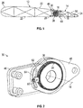
- the actuator 30 includes a position sensing system 60 located thereat to sense and track the rotational position of the output arm 48 relative to the ground arm 46.
- the position sensing system 60 is located at the ground arm 46 and is interactive with a sensed portion 64 located at the output arm 48.
- the position sensing system 60 is a compact sensor which utilizes variations in magnetic reluctance to determine a position of the output arm 48 relative to the ground arm 46.
- the position sensing system 60 includes a magnet 66 used to generate a magnetic field.
- the magnet 66 is disposed at a magnet holder 68 and fixed to the ground arm 46.
- a sensor plug 70, used to control the magnetic field generated by the magnet 66 is positioned in a sensor opening 72 extending through the ground arm 46 toward the output arm 48.
- a hall effect sensor 74 Between the sensor plug 70 and the magnet 66 is a hall effect sensor 74 to sense variations in the magnetic field and varies its output voltage depending on these variations.
- Sensor leads 76 extend from the position sensor 60 to output the hall effect sensor 74 voltage to the controller.
- the sensed portion 64 is located at the output arm 48, and in some embodiments comprises geometric variation in a surface 62 of the output arm 48. As shown in FIG. 3 and FIG. 4 , the sensed portion 64 may comprise a groove 78 in the output arm 48.
- the groove 78 is centered on a sensor axis 80 and as shown in FIG. 4 , is progressively wider and/or deeper as groove 78 extends circumferentially around the axis of rotation 16.
- the variation in groove 78 width and/or depth is that, as the output arm 48 is rotated about the axis of rotation 16 relative to the ground arm 46, a different reluctance in the magnetic field will be sensed by the relatively fixed position sensing system 60 fixed at the ground arm 46. Thus, magnetic reluctance becomes a function of angular position of the ground arm 46.
- the geometric variation may be a pattern of circular holes 82, which increase in diameter and/or depth as the pattern extends circumferentially about the axis of rotation 16. Further, in some embodiments, the pattern of circular holes 82 may vary in spacing in addition to, or as an alternative to, varying in diameter and/or depth.
- the position sensing system 60 may include two position sensing system 60 and two sensed portions 64, located at opposite faces of the output arm 48.
- the geometric variations at the opposing faces of the output arm 48 may be substantially opposing.
- the groove 78 is at its widest and/or deepest at a first face of the output arm 48
- the opposing groove 78 at an opposing second face of the output arm 48 is at its narrowest and/or shallowest. The same duplication may be done with the embodiment of FIG. 5 .
- a reluctance-based position sensing system 60 for the actuator 30 allows the position sensing system 60 to be smaller and less costly than a typical actuator position sensor, and will further enable angular position sensing upon powering up, without needing slight movement of the output arm to ascertain position.
Landscapes
- Physics & Mathematics (AREA)
- General Physics & Mathematics (AREA)
- Engineering & Computer Science (AREA)
- Mechanical Engineering (AREA)
- Automation & Control Theory (AREA)
- Aviation & Aerospace Engineering (AREA)
- Transmission And Conversion Of Sensor Element Output (AREA)
- Measurement Of Length, Angles, Or The Like Using Electric Or Magnetic Means (AREA)
Applications Claiming Priority (1)
| Application Number | Priority Date | Filing Date | Title |
|---|---|---|---|
| US14/993,730 US10266251B2 (en) | 2016-01-12 | 2016-01-12 | Position sensor for electromechanical actuator |
Publications (2)
| Publication Number | Publication Date |
|---|---|
| EP3193141A1 true EP3193141A1 (fr) | 2017-07-19 |
| EP3193141B1 EP3193141B1 (fr) | 2018-08-29 |
Family
ID=57326204
Family Applications (1)
| Application Number | Title | Priority Date | Filing Date |
|---|---|---|---|
| EP16198514.8A Active EP3193141B1 (fr) | 2016-01-12 | 2016-11-11 | Capteur de position d'actionneur électromécanique |
Country Status (2)
| Country | Link |
|---|---|
| US (1) | US10266251B2 (fr) |
| EP (1) | EP3193141B1 (fr) |
Families Citing this family (3)
| Publication number | Priority date | Publication date | Assignee | Title |
|---|---|---|---|---|
| US11085518B2 (en) * | 2019-04-18 | 2021-08-10 | Hamilton Sunstrand Corporation | Inverted compound harmonic drive |
| EP4106159B1 (fr) * | 2021-06-18 | 2025-12-03 | Goodrich Actuation Systems Limited | Surveillance de l'état de santé d'actionneurs de ligne de charnière multicoupe |
| US12140213B2 (en) * | 2021-08-11 | 2024-11-12 | Hamilton Sundstrand Corporation | Compound harmonic gear system with dual output arms |
Citations (5)
| Publication number | Priority date | Publication date | Assignee | Title |
|---|---|---|---|---|
| US4967154A (en) * | 1989-09-13 | 1990-10-30 | Optima Industries, Inc. | Dynamic tube runout measuring method and apparatus with square wave energized reluctance measuring coils |
| US5428290A (en) * | 1991-11-26 | 1995-06-27 | Societe D'applications Generales D'electricite Et De Mecanique Sagem | Variable reluctance absolute angular position sensor with sectored housing and rotor |
| US20100181993A1 (en) * | 2009-01-19 | 2010-07-22 | Devon Fernandez | Direction detection sensor |
| WO2015068061A2 (fr) * | 2013-11-06 | 2015-05-14 | Corephotonics Ltd. | Détection de position basée sur l'inductance dans un actionneur de caméra numérique |
| US20150253153A1 (en) * | 2014-03-07 | 2015-09-10 | Jeffrey R. Smithanik | Variable Reluctance Resolve-Encoder |
Family Cites Families (4)
| Publication number | Priority date | Publication date | Assignee | Title |
|---|---|---|---|---|
| FR2670286B1 (fr) * | 1990-12-05 | 1993-03-26 | Moving Magnet Tech | Capteur magnetique de position et de vitesse a sonde de hall. |
| US5670876A (en) * | 1995-11-14 | 1997-09-23 | Fisher Controls International, Inc. | Magnetic displacement sensor including first and second flux paths wherein the first path has a fixed reluctance and a sensor disposed therein |
| US6124709A (en) * | 1998-06-05 | 2000-09-26 | Cts Corporation | Magnetic position sensor having a variable width magnet mounted into a rotating disk and a hall effect sensor |
| DE102008028618B3 (de) | 2008-06-18 | 2009-11-12 | Ecs Engineered Control Systems Ag | Elektromechanische Gebereinrichtung |
-
2016
- 2016-01-12 US US14/993,730 patent/US10266251B2/en active Active
- 2016-11-11 EP EP16198514.8A patent/EP3193141B1/fr active Active
Patent Citations (5)
| Publication number | Priority date | Publication date | Assignee | Title |
|---|---|---|---|---|
| US4967154A (en) * | 1989-09-13 | 1990-10-30 | Optima Industries, Inc. | Dynamic tube runout measuring method and apparatus with square wave energized reluctance measuring coils |
| US5428290A (en) * | 1991-11-26 | 1995-06-27 | Societe D'applications Generales D'electricite Et De Mecanique Sagem | Variable reluctance absolute angular position sensor with sectored housing and rotor |
| US20100181993A1 (en) * | 2009-01-19 | 2010-07-22 | Devon Fernandez | Direction detection sensor |
| WO2015068061A2 (fr) * | 2013-11-06 | 2015-05-14 | Corephotonics Ltd. | Détection de position basée sur l'inductance dans un actionneur de caméra numérique |
| US20150253153A1 (en) * | 2014-03-07 | 2015-09-10 | Jeffrey R. Smithanik | Variable Reluctance Resolve-Encoder |
Also Published As
| Publication number | Publication date |
|---|---|
| US10266251B2 (en) | 2019-04-23 |
| EP3193141B1 (fr) | 2018-08-29 |
| US20170197704A1 (en) | 2017-07-13 |
Similar Documents
| Publication | Publication Date | Title |
|---|---|---|
| US8075249B2 (en) | System and a method for dynamically balancing a blade | |
| EP3208189B1 (fr) | Système de surveillance de mouvement de surface de commande aérodynamique | |
| EP2681114B1 (fr) | Procédé de commande simultanée d'actionneurs de déplacement de volets d'aéronef, dispositif de motorisation de volets d'aéronef et aéronef pourvu d'un tel dispositif | |
| CN105691592B (zh) | 机电铰链线旋转致动器 | |
| EP3032725B1 (fr) | Actionneur électromécanique rotatif multicoupe | |
| EP3193141B1 (fr) | Capteur de position d'actionneur électromécanique | |
| EP3381796B1 (fr) | Système de surveillance de mouvement de surface de commande aérodynamique d'aéronef | |
| US10279900B2 (en) | Rotorcraft variable thrust cross-flow fan systems | |
| CA3077940A1 (fr) | Systeme de retroaction de position d`angle de pale avec capteurs de decalage | |
| EP3591343B1 (fr) | Unité de commande pilote comprenant un capteur de position redondant | |
| EP3388332B1 (fr) | Système de surveillance de mouvement de surface de commande aérodynamique à réflexion laser | |
| EP3712057B1 (fr) | Système de rétroaction de position angulaire de pale avec marqueurs étendus | |
| CN103674474B (zh) | 全机风洞实验舵面操纵装置失效模拟装置 | |
| US10308355B2 (en) | Hub mounted vibration suppression system | |
| EP3055207B1 (fr) | Système et procédé de mesure d'angle de battement d'hélicoptère | |
| CN112141322A (zh) | 用传感器测量多个控制表面的方法和装置 | |
| EP3766776B1 (fr) | Système de rétroaction de position angulaire de pale à blindage magnétique | |
| KR102116859B1 (ko) | 항공기용 전기식 구동장치의 지터현상 방지 시스템 | |
| WO2016200458A2 (fr) | Plateau cyclique à commande monocyclique | |
| WO2016076937A1 (fr) | Détection de niveau de lubrifiant pour actionneur | |
| EP2487108A2 (fr) | Dispositif modulaire intégré pour contrôle une pale de rotor | |
| BR102019006042B1 (pt) | Unidade de controle piloto, e, método para fabricar uma unidade de controle piloto |
Legal Events
| Date | Code | Title | Description |
|---|---|---|---|
| PUAI | Public reference made under article 153(3) epc to a published international application that has entered the european phase |
Free format text: ORIGINAL CODE: 0009012 |
|
| STAA | Information on the status of an ep patent application or granted ep patent |
Free format text: STATUS: THE APPLICATION HAS BEEN PUBLISHED |
|
| AK | Designated contracting states |
Kind code of ref document: A1 Designated state(s): AL AT BE BG CH CY CZ DE DK EE ES FI FR GB GR HR HU IE IS IT LI LT LU LV MC MK MT NL NO PL PT RO RS SE SI SK SM TR |
|
| AX | Request for extension of the european patent |
Extension state: BA ME |
|
| STAA | Information on the status of an ep patent application or granted ep patent |
Free format text: STATUS: REQUEST FOR EXAMINATION WAS MADE |
|
| 17P | Request for examination filed |
Effective date: 20180119 |
|
| RBV | Designated contracting states (corrected) |
Designated state(s): AL AT BE BG CH CY CZ DE DK EE ES FI FR GB GR HR HU IE IS IT LI LT LU LV MC MK MT NL NO PL PT RO RS SE SI SK SM TR |
|
| GRAP | Despatch of communication of intention to grant a patent |
Free format text: ORIGINAL CODE: EPIDOSNIGR1 |
|
| STAA | Information on the status of an ep patent application or granted ep patent |
Free format text: STATUS: GRANT OF PATENT IS INTENDED |
|
| RIC1 | Information provided on ipc code assigned before grant |
Ipc: G01D 5/20 20060101AFI20180209BHEP Ipc: G01D 5/14 20060101ALI20180209BHEP Ipc: B64C 13/28 20060101ALI20180209BHEP Ipc: G01B 7/30 20060101ALI20180209BHEP |
|
| INTG | Intention to grant announced |
Effective date: 20180305 |
|
| GRAS | Grant fee paid |
Free format text: ORIGINAL CODE: EPIDOSNIGR3 |
|
| GRAA | (expected) grant |
Free format text: ORIGINAL CODE: 0009210 |
|
| STAA | Information on the status of an ep patent application or granted ep patent |
Free format text: STATUS: THE PATENT HAS BEEN GRANTED |
|
| AK | Designated contracting states |
Kind code of ref document: B1 Designated state(s): AL AT BE BG CH CY CZ DE DK EE ES FI FR GB GR HR HU IE IS IT LI LT LU LV MC MK MT NL NO PL PT RO RS SE SI SK SM TR |
|
| REG | Reference to a national code |
Ref country code: GB Ref legal event code: FG4D |
|
| REG | Reference to a national code |
Ref country code: CH Ref legal event code: EP |
|
| REG | Reference to a national code |
Ref country code: AT Ref legal event code: REF Ref document number: 1035654 Country of ref document: AT Kind code of ref document: T Effective date: 20180915 |
|
| REG | Reference to a national code |
Ref country code: IE Ref legal event code: FG4D |
|
| REG | Reference to a national code |
Ref country code: DE Ref legal event code: R096 Ref document number: 602016005150 Country of ref document: DE |
|
| REG | Reference to a national code |
Ref country code: FR Ref legal event code: PLFP Year of fee payment: 3 |
|
| REG | Reference to a national code |
Ref country code: NL Ref legal event code: MP Effective date: 20180829 |
|
| REG | Reference to a national code |
Ref country code: LT Ref legal event code: MG4D |
|
| PG25 | Lapsed in a contracting state [announced via postgrant information from national office to epo] |
Ref country code: NO Free format text: LAPSE BECAUSE OF FAILURE TO SUBMIT A TRANSLATION OF THE DESCRIPTION OR TO PAY THE FEE WITHIN THE PRESCRIBED TIME-LIMIT Effective date: 20181129 Ref country code: BG Free format text: LAPSE BECAUSE OF FAILURE TO SUBMIT A TRANSLATION OF THE DESCRIPTION OR TO PAY THE FEE WITHIN THE PRESCRIBED TIME-LIMIT Effective date: 20181129 Ref country code: SE Free format text: LAPSE BECAUSE OF FAILURE TO SUBMIT A TRANSLATION OF THE DESCRIPTION OR TO PAY THE FEE WITHIN THE PRESCRIBED TIME-LIMIT Effective date: 20180829 Ref country code: IS Free format text: LAPSE BECAUSE OF FAILURE TO SUBMIT A TRANSLATION OF THE DESCRIPTION OR TO PAY THE FEE WITHIN THE PRESCRIBED TIME-LIMIT Effective date: 20181229 Ref country code: LT Free format text: LAPSE BECAUSE OF FAILURE TO SUBMIT A TRANSLATION OF THE DESCRIPTION OR TO PAY THE FEE WITHIN THE PRESCRIBED TIME-LIMIT Effective date: 20180829 Ref country code: NL Free format text: LAPSE BECAUSE OF FAILURE TO SUBMIT A TRANSLATION OF THE DESCRIPTION OR TO PAY THE FEE WITHIN THE PRESCRIBED TIME-LIMIT Effective date: 20180829 Ref country code: GR Free format text: LAPSE BECAUSE OF FAILURE TO SUBMIT A TRANSLATION OF THE DESCRIPTION OR TO PAY THE FEE WITHIN THE PRESCRIBED TIME-LIMIT Effective date: 20181130 Ref country code: RS Free format text: LAPSE BECAUSE OF FAILURE TO SUBMIT A TRANSLATION OF THE DESCRIPTION OR TO PAY THE FEE WITHIN THE PRESCRIBED TIME-LIMIT Effective date: 20180829 Ref country code: FI Free format text: LAPSE BECAUSE OF FAILURE TO SUBMIT A TRANSLATION OF THE DESCRIPTION OR TO PAY THE FEE WITHIN THE PRESCRIBED TIME-LIMIT Effective date: 20180829 |
|
| REG | Reference to a national code |
Ref country code: AT Ref legal event code: MK05 Ref document number: 1035654 Country of ref document: AT Kind code of ref document: T Effective date: 20180829 |
|
| PG25 | Lapsed in a contracting state [announced via postgrant information from national office to epo] |
Ref country code: HR Free format text: LAPSE BECAUSE OF FAILURE TO SUBMIT A TRANSLATION OF THE DESCRIPTION OR TO PAY THE FEE WITHIN THE PRESCRIBED TIME-LIMIT Effective date: 20180829 Ref country code: AL Free format text: LAPSE BECAUSE OF FAILURE TO SUBMIT A TRANSLATION OF THE DESCRIPTION OR TO PAY THE FEE WITHIN THE PRESCRIBED TIME-LIMIT Effective date: 20180829 Ref country code: LV Free format text: LAPSE BECAUSE OF FAILURE TO SUBMIT A TRANSLATION OF THE DESCRIPTION OR TO PAY THE FEE WITHIN THE PRESCRIBED TIME-LIMIT Effective date: 20180829 |
|
| PG25 | Lapsed in a contracting state [announced via postgrant information from national office to epo] |
Ref country code: EE Free format text: LAPSE BECAUSE OF FAILURE TO SUBMIT A TRANSLATION OF THE DESCRIPTION OR TO PAY THE FEE WITHIN THE PRESCRIBED TIME-LIMIT Effective date: 20180829 Ref country code: AT Free format text: LAPSE BECAUSE OF FAILURE TO SUBMIT A TRANSLATION OF THE DESCRIPTION OR TO PAY THE FEE WITHIN THE PRESCRIBED TIME-LIMIT Effective date: 20180829 Ref country code: RO Free format text: LAPSE BECAUSE OF FAILURE TO SUBMIT A TRANSLATION OF THE DESCRIPTION OR TO PAY THE FEE WITHIN THE PRESCRIBED TIME-LIMIT Effective date: 20180829 Ref country code: PL Free format text: LAPSE BECAUSE OF FAILURE TO SUBMIT A TRANSLATION OF THE DESCRIPTION OR TO PAY THE FEE WITHIN THE PRESCRIBED TIME-LIMIT Effective date: 20180829 Ref country code: CZ Free format text: LAPSE BECAUSE OF FAILURE TO SUBMIT A TRANSLATION OF THE DESCRIPTION OR TO PAY THE FEE WITHIN THE PRESCRIBED TIME-LIMIT Effective date: 20180829 Ref country code: ES Free format text: LAPSE BECAUSE OF FAILURE TO SUBMIT A TRANSLATION OF THE DESCRIPTION OR TO PAY THE FEE WITHIN THE PRESCRIBED TIME-LIMIT Effective date: 20180829 |
|
| PG25 | Lapsed in a contracting state [announced via postgrant information from national office to epo] |
Ref country code: SK Free format text: LAPSE BECAUSE OF FAILURE TO SUBMIT A TRANSLATION OF THE DESCRIPTION OR TO PAY THE FEE WITHIN THE PRESCRIBED TIME-LIMIT Effective date: 20180829 Ref country code: DK Free format text: LAPSE BECAUSE OF FAILURE TO SUBMIT A TRANSLATION OF THE DESCRIPTION OR TO PAY THE FEE WITHIN THE PRESCRIBED TIME-LIMIT Effective date: 20180829 Ref country code: SM Free format text: LAPSE BECAUSE OF FAILURE TO SUBMIT A TRANSLATION OF THE DESCRIPTION OR TO PAY THE FEE WITHIN THE PRESCRIBED TIME-LIMIT Effective date: 20180829 |
|
| REG | Reference to a national code |
Ref country code: DE Ref legal event code: R097 Ref document number: 602016005150 Country of ref document: DE |
|
| PLBE | No opposition filed within time limit |
Free format text: ORIGINAL CODE: 0009261 |
|
| STAA | Information on the status of an ep patent application or granted ep patent |
Free format text: STATUS: NO OPPOSITION FILED WITHIN TIME LIMIT |
|
| PG25 | Lapsed in a contracting state [announced via postgrant information from national office to epo] |
Ref country code: LU Free format text: LAPSE BECAUSE OF NON-PAYMENT OF DUE FEES Effective date: 20181111 Ref country code: MC Free format text: LAPSE BECAUSE OF FAILURE TO SUBMIT A TRANSLATION OF THE DESCRIPTION OR TO PAY THE FEE WITHIN THE PRESCRIBED TIME-LIMIT Effective date: 20180829 |
|
| 26N | No opposition filed |
Effective date: 20190531 |
|
| REG | Reference to a national code |
Ref country code: BE Ref legal event code: MM Effective date: 20181130 |
|
| REG | Reference to a national code |
Ref country code: IE Ref legal event code: MM4A |
|
| PG25 | Lapsed in a contracting state [announced via postgrant information from national office to epo] |
Ref country code: SI Free format text: LAPSE BECAUSE OF FAILURE TO SUBMIT A TRANSLATION OF THE DESCRIPTION OR TO PAY THE FEE WITHIN THE PRESCRIBED TIME-LIMIT Effective date: 20180829 |
|
| PG25 | Lapsed in a contracting state [announced via postgrant information from national office to epo] |
Ref country code: IE Free format text: LAPSE BECAUSE OF NON-PAYMENT OF DUE FEES Effective date: 20181111 |
|
| PG25 | Lapsed in a contracting state [announced via postgrant information from national office to epo] |
Ref country code: BE Free format text: LAPSE BECAUSE OF NON-PAYMENT OF DUE FEES Effective date: 20181130 |
|
| PG25 | Lapsed in a contracting state [announced via postgrant information from national office to epo] |
Ref country code: MT Free format text: LAPSE BECAUSE OF NON-PAYMENT OF DUE FEES Effective date: 20181111 |
|
| PG25 | Lapsed in a contracting state [announced via postgrant information from national office to epo] |
Ref country code: TR Free format text: LAPSE BECAUSE OF FAILURE TO SUBMIT A TRANSLATION OF THE DESCRIPTION OR TO PAY THE FEE WITHIN THE PRESCRIBED TIME-LIMIT Effective date: 20180829 |
|
| PG25 | Lapsed in a contracting state [announced via postgrant information from national office to epo] |
Ref country code: PT Free format text: LAPSE BECAUSE OF FAILURE TO SUBMIT A TRANSLATION OF THE DESCRIPTION OR TO PAY THE FEE WITHIN THE PRESCRIBED TIME-LIMIT Effective date: 20180829 |
|
| PG25 | Lapsed in a contracting state [announced via postgrant information from national office to epo] |
Ref country code: CY Free format text: LAPSE BECAUSE OF FAILURE TO SUBMIT A TRANSLATION OF THE DESCRIPTION OR TO PAY THE FEE WITHIN THE PRESCRIBED TIME-LIMIT Effective date: 20180829 Ref country code: HU Free format text: LAPSE BECAUSE OF FAILURE TO SUBMIT A TRANSLATION OF THE DESCRIPTION OR TO PAY THE FEE WITHIN THE PRESCRIBED TIME-LIMIT; INVALID AB INITIO Effective date: 20161111 Ref country code: MK Free format text: LAPSE BECAUSE OF NON-PAYMENT OF DUE FEES Effective date: 20180829 |
|
| REG | Reference to a national code |
Ref country code: CH Ref legal event code: PL |
|
| PG25 | Lapsed in a contracting state [announced via postgrant information from national office to epo] |
Ref country code: CH Free format text: LAPSE BECAUSE OF NON-PAYMENT OF DUE FEES Effective date: 20191130 Ref country code: LI Free format text: LAPSE BECAUSE OF NON-PAYMENT OF DUE FEES Effective date: 20191130 |
|
| P01 | Opt-out of the competence of the unified patent court (upc) registered |
Effective date: 20230522 |
|
| PGFP | Annual fee paid to national office [announced via postgrant information from national office to epo] |
Ref country code: DE Payment date: 20251117 Year of fee payment: 10 |
|
| PGFP | Annual fee paid to national office [announced via postgrant information from national office to epo] |
Ref country code: GB Payment date: 20251126 Year of fee payment: 10 |
|
| PGFP | Annual fee paid to national office [announced via postgrant information from national office to epo] |
Ref country code: IT Payment date: 20251111 Year of fee payment: 10 |
|
| PGFP | Annual fee paid to national office [announced via postgrant information from national office to epo] |
Ref country code: FR Payment date: 20251128 Year of fee payment: 10 |