EP3193191B1 - Verfahren und system zur messung von standort und/oder ausrichtung - Google Patents
Verfahren und system zur messung von standort und/oder ausrichtung Download PDFInfo
- Publication number
- EP3193191B1 EP3193191B1 EP16151513.5A EP16151513A EP3193191B1 EP 3193191 B1 EP3193191 B1 EP 3193191B1 EP 16151513 A EP16151513 A EP 16151513A EP 3193191 B1 EP3193191 B1 EP 3193191B1
- Authority
- EP
- European Patent Office
- Prior art keywords
- communication device
- signal
- beacon
- signals
- movable
- Prior art date
- Legal status (The legal status is an assumption and is not a legal conclusion. Google has not performed a legal analysis and makes no representation as to the accuracy of the status listed.)
- Active
Links
Images


Classifications
-
- G—PHYSICS
- G01—MEASURING; TESTING
- G01S—RADIO DIRECTION-FINDING; RADIO NAVIGATION; DETERMINING DISTANCE OR VELOCITY BY USE OF RADIO WAVES; LOCATING OR PRESENCE-DETECTING BY USE OF THE REFLECTION OR RERADIATION OF RADIO WAVES; ANALOGOUS ARRANGEMENTS USING OTHER WAVES
- G01S13/00—Systems using the reflection or reradiation of radio waves, e.g. radar systems; Analogous systems using reflection or reradiation of waves whose nature or wavelength is irrelevant or unspecified
- G01S13/87—Combinations of radar systems, e.g. primary radar and secondary radar
- G01S13/878—Combination of several spaced transmitters or receivers of known location for determining the position of a transponder or a reflector
-
- G—PHYSICS
- G01—MEASURING; TESTING
- G01S—RADIO DIRECTION-FINDING; RADIO NAVIGATION; DETERMINING DISTANCE OR VELOCITY BY USE OF RADIO WAVES; LOCATING OR PRESENCE-DETECTING BY USE OF THE REFLECTION OR RERADIATION OF RADIO WAVES; ANALOGOUS ARRANGEMENTS USING OTHER WAVES
- G01S13/00—Systems using the reflection or reradiation of radio waves, e.g. radar systems; Analogous systems using reflection or reradiation of waves whose nature or wavelength is irrelevant or unspecified
- G01S13/74—Systems using reradiation of radio waves, e.g. secondary radar systems; Analogous systems
-
- G—PHYSICS
- G01—MEASURING; TESTING
- G01S—RADIO DIRECTION-FINDING; RADIO NAVIGATION; DETERMINING DISTANCE OR VELOCITY BY USE OF RADIO WAVES; LOCATING OR PRESENCE-DETECTING BY USE OF THE REFLECTION OR RERADIATION OF RADIO WAVES; ANALOGOUS ARRANGEMENTS USING OTHER WAVES
- G01S15/00—Systems using the reflection or reradiation of acoustic waves, e.g. sonar systems
- G01S15/74—Systems using reradiation of acoustic waves, e.g. IFF, i.e. identification of friend or foe
-
- G—PHYSICS
- G01—MEASURING; TESTING
- G01S—RADIO DIRECTION-FINDING; RADIO NAVIGATION; DETERMINING DISTANCE OR VELOCITY BY USE OF RADIO WAVES; LOCATING OR PRESENCE-DETECTING BY USE OF THE REFLECTION OR RERADIATION OF RADIO WAVES; ANALOGOUS ARRANGEMENTS USING OTHER WAVES
- G01S15/00—Systems using the reflection or reradiation of acoustic waves, e.g. sonar systems
- G01S15/87—Combinations of sonar systems
- G01S15/876—Combination of several spaced transmitters or receivers of known location for determining the position of a transponder or a reflector
Definitions
- the present invention relates to a method and a system measuring location and/or orientation of one or several communication devices.
- the invention also relates to low-uncertainty location and orientation measurements, in particular based on coded signals, time-to-digital conversion, and matched filters.
- Camera-based techniques require a line of sight between the measuring cameras and the objects/people.
- Radio Frequency (RF)-based approaches are also known.
- energy-based approaches have been disclosed by D. Ampeliotis and K. Berberidis, "Low complexity multiple acoustic source location in sensor networks based on energy measurements", Signal Processing, Elsevier, vol. 90, no. 4, pp. 1300-1312, 2010 .
- US 2014/057655 A1 discloses a method for localizing a target device by means of two different devices which are a master device and a slave device. No beacon system is disclosed. No orthogonal codes or matched filters are suggested. No different receivers placed in different axes are disclosed.
- US 2008/165059 A1 discloses a system for locating objects and for communication to be implanted in a bionic device implanted on a living body.
- a remote locator is arranged to communicate with a transponder or micro-transponder. The communications make use of a roundtrip Doppler shift technique.
- the present invention is a.
- the present invention relates to a method for measuring the location of a communication device with respect to a three axis position system (for example defined by a beacon).
- the method comprises:
- a plurality of movable communication devices (e.g. a group of at least a first, a second and a third communication device) can be located. It has been noted, in fact, that the execution time of the measurements is enough low and deterministic.
- the plurality of movable communication devices can comprise a group of three movable communication devices (a first movable communication device, a second movable communication device, and a third movable communication device) positioned so as to span a plane.
- the orientation of the plane can be measured.
- the invention can comprise a step of determining the orientation of an object on the basis of the ToF measurements of the first signals and the second signals.
- the invention can be embodied by a method for measuring the location and/or orientation of a group of communication devices with respect to a three axis position system (e.g., defined by a beacon), the communication devices including at least a first, a second, and a third movable communication devices, the method providing for iteratively selecting, in turn, one of the communication devices and performing the following communication procedure: transmitting, from a main transmitter placed, a first signal; detecting, by the first, second and third movable communication devices, the first signal; transmitting, from the selected movable communication device, a second signal; and, using matched filters, detecting, by a main receiver and a first, a second, and a third axis-placed receivers (in some embodiments also by the non-selected communication
- a determination step using ToF measurements of the second signal from the selected movable communication device, the main receiver and the axis-placed receivers can be implemented.
- a step of refining the measurements using ToF measurements of the second signal between the selected communication device and the non-selected communication devices can be implemented.
- the signals can be acoustic signals or radio-frequency, RF, signals.
- the invention it is possible to measure the location, the movements and/or the orientation of an object or a living body such as an animal or a person by using the inventive method after having applied the communication device/s to the object or living body.
- the invention also relates to a system for measuring location and/or orientation, comprising: at least a movable communication device and a movable communication device processor associated to the movable communication device, and a three-axis beacon system.
- the beacon system includes a main transmitter, a main receiver, a first, a second, and a third axis-placed receivers, respectively, placed at different axes of the beacon system, and a beacon processor.
- the beacon processor is configured to control the transmission of a first signal; the movable communication device processor is configured to control the detection of the first signal; the movable communication device processor is configured to control the transmission of a second signal from the movable communication device; the beacon processor is configured to control the detection of the second signal; and the beacon processor is also configured to determine the location of the movable communication device using ToF measurements of the first and second signals.
- the first and the second signals are orthogonal coded signals. Matched filters are used for the detection of codes associated to the first and second signals.
- the invention also relates to a system structurally and functionally configured to perform a method according to the invention.
- a rigid structure can be provided for fixing the communication devices (e.g. so as to span plane).
- the invention also relates to a system for measuring location and/or orientation comprising: at least a first, a second, and a third movable communication device positioned with respect to each other so as to span a plane; and movable communication device processors associated to the movable communication devices.
- the system comprises a three-axis beacon system including: a main transmitter (which can be positioned at the origin of the beacon system); a main receiver (which can be positioned at the origin of the beacon system); a first, a second, and a third axis-placed receiver, respectively, placed at different axes of the beacon system; and a beacon processor configured to iteratively select, in turn, each of the movable communication devices.
- the beacon processor controls the transmission of a first signal selecting one of the communication devices.
- Each of the movable communication device processors controls the detection of the first signal.
- Each of the movable communication device processors when the associated movable communication device is selected, controls the transmission of a second signal.
- the beacon processor and the movable communication device processors associated to the non-selected communication devices control the detection of the second signal.
- the beacon processor determines the location of each movable communication device using ToF measurements of the first and second signals.
- the movable communication devices, the main receiver, and the axis-placed receivers use matched filters for the detection of codes associated to the first and second signals.
- the invention also relates to a beacon system as a single, standalone product when configured for the inventive system and/or adapted to perform the inventive method.
- the invention also relates to a communication device as a single, standalone product, when configured for the inventive system and/or adapted to perform the inventive method.
- the invention also relates to the use of the inventive system or method to localize and to measure the orientation of an object or a living body, such as an animal or person, associated to the communication devices.
- the invention can be embodied by a keyless system, in which communication device/s is/are attached to (or incorporated as a single piece) to a structure embodying a key, and the beacon is attached to a fixed environment.
- the invention can be embodied by a tracking system, in which communication device/s is/are carried by a person.
- the invention can be embodied by a housing of a portable radio device (e.g., a tactical portable radio), wherein communication device/s is/are attached thereto.
- a portable radio device e.g., a tactical portable radio
- the invention can be embodied using a mobile terminal, a cellular phone, a smartphone, a portable computer, a tablet, or similar mobile device, wherein communication device/s is/are attached thereto, e.g. to the housing.
- the invention also relates to a tag to which communication device/s is/are applied or incorporated in one piece.
- the tag can be marketed independently of the beacon system, and can be associated to the particular beacon system after they have been purchased.
- the invention can be embodied by a 3D video or audio system, in which communication device/s is/are associated to the user.
- the invention can be embodied by a museum system (or a touristic system), in which communication device/s is/are attached (or are a part of) a device associated to the user (or the tourist), such as an audioguide (or another kind of portable terminal).
- a museum system or a touristic system
- communication device/s is/are attached (or are a part of) a device associated to the user (or the tourist), such as an audioguide (or another kind of portable terminal).
- the invention can be embodied by hospital systems (or firefighting systems), in which communication device/s is/are attached are applied to one/more tag/s associated to a clinician or to a patient or to an equipment for carrying the patient (or to a firefighting element such as a vehicle).
- the invention can be applied to electronics devices, or to electronic devices in general which can recognize and localize other electronic devices.
- the invention also relates to the use of the inventive system and/or inventive method to localize an object or a living body.
- inventive system and/or inventive method to localize an object or a living body.
- Communication devices can be associated to the object or living body. Mutual distances between different parts of the body (such as limbs) can be measured when different movable communication devices are placed on different parts of the body, such as limbs.
- Fig. 1A shows a system 10, comprising at least one movable communication device.
- the at least one movable communication device comprises a group of at least a first, a second and a third communication device 21, 22, 23.
- the at least three communication devices 21, 22, 23 span a plane. Besides the three span-planning communication devices, other communication devices (either coplanar or non-coplanar) can be provided.
- a movable element 20 is formed by the first, the second, and the third movable communication device 21, 22, 23 (also indicated with CD 1 , CD 2 , CD 3 ).
- a structure 24 is provided to maintain the mutual positions between the movable communication devices 21-23.
- the structure 24 can be applied to a commercial item 24' (the shape of the structure 24 and the commercial item 24' can be different). At least some or all of the communication devices 21-23, the structure 24 and the commercial item 24' are fixed to each other (e.g., incorporated in one single piece, glued, screwed, nailed, or welded). Some or all of the communication devices 21-23, the structure 24 and the commercial item 24' can also be provided with means that permit to engagement/disengagement. In some embodiments, the structure 24 can be applied to a living body, in particular an animal, in particular a person.
- Fig. 1B shows a system 10, comprising at least one movable communication device.
- the at least one movable communication device comprises a first, a second and a third communication device 21, 22, 23 (CD1, CD2, CD3).
- the communication devices 21, 22, 23 do not necessarily span a plane.
- the movable communication devices 21, 22, 23 can be movable with respect to each other, e.g. in view of a lack of a structure such as the structure 24.
- the location the at least one movable communication device can be measured in a three-axis position system with three axes X, Y, Z which generate a space (in this embodiment, the axes X, Y, Z are orthogonal to each other).
- a movable communication device processor 25 controls a receiver 26 (also indicated as RX CD1 , RX CD2 , RX CD3 ) and a transmitter 27 (also indicated as TX CD1 , TX CD2 , TX CD3 ).
- a receiver 26 also indicated as RX CD1 , RX CD2 , RX CD3
- a transmitter 27 also indicated as TX CD1 , TX CD2 , TX CD3 .
- code generators and code detectors are also provided.
- a counter section 28 (measuring time) is available to the movable communication device processor 25.
- the counter section 28 can contain one or more registers capable of counting time, in particular independently from each other.
- the movable communication device processor 25 can control the counter section 28, in particular by selecting and initializing registers of the counter section 28 to restart time measurement.
- the registers can be implemented as hardware register and/or software registers.
- the movable communication device processor 25 can also be connected to a storage means 29 to run a software memorized in the storage means 29 and to memorize data.
- the movable communication device processor 25 can be implemented in ASIC, FPGA, or other electronic systems. In some embodiments, the movable communication device processor 25 and/or the counter section 28 and/or the storage means 29 can be implemented in one single controller.
- the movable communication device processor 25 can also be connected to external processors through other input/output (I/O) means, e.g., a serial port, a USB port, etc. Through these I/O means and/or receiver 26 and a transmitter 27, the movable communication device processor 25 can also run a procedure of data upload to external processor entities, e.g. to upload values memorized in the storage means 29.
- I/O input/output
- different communication devices share at least some of the same hardware resources (processor, counter section, storage means, and/or I/O means) and can be placed in positions which are not the same of the transmitter and the receiver. However, when the communication devices need to be coplanar, the transmitters and the receivers are placed in positions which span a plane.
- a single processor can run different tasks for each communication device (e.g. using multitasking techniques) and control the transmitters and the receivers independently.
- Matched filters can be implemented by hardware and/or software resources.
- Orthogonal codes are also used for the communications. Codes with low cross correlation are preferred. GOLD or Kasami codes can be used. These codes also provide for appropriate identification between the communication devices.
- the three-axis position system can be obtained using a beacon system 30 (also indicated as BC).
- the beacon system 30 and the at least one communication device are structurally separated from each other.
- the beacon system 30 and the at least one communication device communicate wirelessly to each other.
- the beacon system 30 has no wired connection to any of the communication devices.
- the beacon system 30 comprises a main transmitter/receiver 31 (also indicated as TxRx BC0 ), which can be embodied by a single device or by a transmitter and receiver separated from each other.
- the main transmitter/receiver 31 is placed at the origin O of the space generated by the axes X, Y, Z, so as to simplify calculations.
- the beacon system 30 also comprises a first, a second, and a third axis-placed receivers 32, 33, 34 (also indicated as RX BCX , RX BCY , RX BCZ ), respectively, placed at axes X, Y, Z.
- the axis-placed receivers 32, 33, 34 are in a fixed relative position with respect to each other. None of the axis-placed receivers is in a position coincident with the position of the transmitter/receiver 31.
- a structure can be used to keep the relative position between the elements to the beacon system 30.
- Engaging/disengaging means can also be provided to attach the elements of the beacon system 30 to an existing structural element or environment.
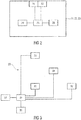
- a scheme of the beacon system 30 is shown in Fig. 3 .
- a beacon processor 35 controls the transmitter/receiver 31 and the axis-placed receivers 32, 33, 34.
- a counter section 38 (measuring time) is available to the beacon processor 35.
- the counter section 38 can contain one or more registers capable of counting time, in particular independently from each other.
- the beacon processor 35 can control the counter section 38, in particular by addressing and initializing one or more of the registers of the counter section 38 to restart time measurement.
- the registers can be implemented as hardware register and/or software registers.
- the beacon processor 35 can also be connected to a storage means 39 (which can include a RAM, a ROM., a flash memory, etc.) in which software is memorized.
- the storage means 39 can also comprise a data memory (e.g., a RAM) to memorize data (such as counter values obtained by the registers of the counter section 38).
- the beacon processor 35 can be implemented in ASIC, FPGA, or other electronic systems. In some embodiments, the beacon processor 35 and/or the counter section 38 and/or the storage means 39 can be implemented in one single controller.
- the beacon processor 35 is connected to the transmitter/receiver 31 and the axis-placed receivers 32, 33, 34 through a connection such as a point-to-point star-connection. It is also possible to use a communication network or a wireless connection.
- the beacon processor can be embodied by a plurality of processor means.
- the first, second, and third axis-placed receivers could be associated to respective first, second, and third CPUs, while the transmitter/receiver could be associated to a fourth CPU.
- the CPUs could communicate data with each other, e.g. by using a network or point-to-point connections. Devices such as DSPs can also be provided.
- the beacon processor can also be formed by at least two different processors: a first processor which controls real-time activities of the beacon, and a second processor, separated from the beacon, which elaborates the data obtained by the beacon processor and by the movable communication devices processors, e.g. in offline sessions.
- the beacon processor (or one of the processors forming it) can be placed remotely with respect to the transmitter/receiver 31 (which can be notwithstanding placed in a different place, such as the origin O).
- the beacon processor 35 can also be connected, either permanently or temporarily, to external computer entities through other input/output (I/O) means, e.g., a serial port, a USB port, etc. Through these I/O means and/or the transmitter/receiver 31, the beacon processor 35 can also run a procedure of data upload to external computer entities, e.g. to upload values memorized in the storage means 39 (such as counter values obtained by the registers or other calculations performed by the beacon processor 35).
- I/O input/output
- the beacon system also comprises code generators and code detectors for the transmissions and receptions of the beacon elements.
- the signals that are transmitted and received are acoustic signals or RF signals. It is known in the art how to manufacture an acoustic transmitter or receiver and an RF transmitter or receiver.
- the beacon system 30 is capable of obtaining the position and the orientation of the movable element 20, in particular by localizing each of the movable communication devices 21-23 in the three-axis position system.
- the beacon system is configured to transmit and receive coded signals according to orthogonal codes (such as GOLD or Kasami codes).
- orthogonal codes such as GOLD or Kasami codes.
- the main transmitter/receiver 31 transmits a first signal 41.
- the at least one movable communication device 21 detects the first signal 41.
- the at least one movable communication device 21 transmits a second signal 42, which is detected by the transmitter/receiver 31 and the first, second and third axis-placed receivers 32, 33, 34.
- the elements of the system 10 can transmit and receive signals.
- the signals can be associated to events such as "REQUEST_TIMER_STOP”, “TIMER_STOP”, “CD_1_SENDS”, and so on.
- the beacon processor 35 can be configured to iteratively select (e.g., by cycling), in turn, one of the first, second, and third movable communication devices 21-23.
- the beacon processor 35 can initialize the counter section 38, e.g. by initializing four registers (e.g., one register associated to the main transmitter/receiver 31 and one register for each of the axis-placed receivers 32, 33, 34).
- the main transmitter/receiver 31 (here placed in correspondence of the origin O) transmits a first communication signal 41 (multiple arrows refer to the same signal detected by different receivers).
- the selected communication device CD 1 (21) is addressed.
- the signal can encode the following events:
- each movable communication device CD 1 , CD 2 , CD 3 (21-23) receives the first signal 41.
- each communication device can detect "REQUEST_TIMER_STOP" by using matched filters.
- the non-selected communication devices CD 2 , CD 3 start counting time, each in particular starting counter of its counter section 28 (e.g. by initializing a register).
- the selected communication device CD 1 (21) can start waiting for a time slot T wait , so as to wait for the other receivers to be ready.
- the selected communication device CD 1 (21) transmits a second signal 42 in response to the first signal 41.
- the second signal 42 can encode the event "TIMER_STOP".
- the non-selected communication devices CD 2 , CD 3 (22, 23), the main transmitter/receiver TXRX BC0 (31), and each of the first, second, and third axis-placed receivers Rx BCX , Rx BCY , Rx BCZ (32, 33, 34) detect the second signal 42. Matched filters are used for the reception.
- the detection of the second signal 42 is associated to a particular counter value CV(..) that can be acquired by one of the registers in one of the counter sections 28, 38.
- These counter values CV(..) can be memorized in local memories of the beacon system and the communication devices, e.g. in the storage means 29 and 39.
- the distances are measured by determining the time of flight (ToF) of signals 41, 42, and by calculating each length associated to each ToF. Methods that can be implemented in the invention to calculate ToF values are here illustrated.
- CV Rx BC O ToF Tx BC 0 Rx CD 1 + T wait + ToF Tx CD 1 Rx BC 0 + 2 ToF code
- CV Rx BC X ToF Tx BC 0 Rx CD 1 + T wait + ToF Tx CD 1 Rx BC X + 2 ToF code
- CV Rx BC Y ToF Tx BC 0 Rx CD 1 + T wait + ToF Tx CD 1 Rx BC Y + 2 ToF code
- CV Rx BC Z ToF Tx BC 0 Rx CD 1 + T wait + ToF Tx CD 1 Rx BC Z + 2 ToF code
- CV Rx BC O ToF Tx BC 0 Rx CD 2 + T wait + ToF Tx CD 2 Rx BC 0 + 2 ToF code
- CV Rx BC X ToF Tx BC 0 Rx CD 2 + T wait + ToF Tx CD 2 Rx BC X + 2 ToF code
- CV Rx BC Y ToF Tx BC 0 Rx CD 2 + T wait + ToF Tx CD 2 Rx BC Y + 2 ToF code
- CV Rx BC Z ToF Tx BC 0 Rx CD 2 + T wait + ToF Tx CD 2 Rx BC Z + 2 ToF code
- the location of each communication device can be determined, in particular, by triangulation.
- the time of flight measurements can be measured by taking into account the propagation speed of the coded signals (sound or light).
- equations like equations (1)-(6) are solved for each of the communication device which is iteratively selected. With three communication devices, 18 equations are implied. When the equations are solved, the counter values CV(%) are known values and permit to calculate the ToF values.
- a plane e.g., Fig. 1A
- a method step performing the necessary mathematical conversions e.g., outputting the angles between the spanned plane and one or more of the axes of the position system
- More than three movable communication devices can be located.
- One or more non-coplanar movable communication devices can be provided further than the first, second, and third plane-spanning communication devices 21, 22, 23. An orientation measurement can notwithstanding be obtained.
- the at least one (or each of the three) movable communication device(s) transmits time stamps of acquired counter values (e.g., the values obtained by the registers of the counter means 28) to a control unit (which can be a part of the beacon processor 35).
- a measurement can be obtained by repeating the communication procedure and by repeatedly transmitting the counter values using third signals (or wired communication in some embodiments). By repeating the procedure periodically (e.g. every 5 ms or less), it is possible to have the knowledge of the position and/or orientation of the at least one (or three) communication device(s) in real time.
- a real-time implementation can be resumed as follows:
- the counter values are memorized in the storage means 29 of the communication devices 21-23 and uploaded to an external unit (which can also be a part of the beacon processor) in an offline procedure. The same can also be performed for the counter values registered in the counter means 38.
- some of or all the communication devices can be structurally connected to a fixed structure 24 to form a rigid entity (e.g., element 20 in Fig. 1A ) whose position and orientation can be easily determined.
- the entity can be fixedly engaged (or even incorporated as a single piece) to the commercial item 24' whose position is to be determined.
- the entity can be structurally engageable/disengageable through engaging means to an object or a person (or a garment associated to the person), a helmet, or the like.
- equations (1)-(6) could seem not suitable to take in account the relative motion between the communication devices (e.g., for motion blur).
- the communication devices can also be in a "quasi fixed motion", such that different communication devices are in relative motion with speed less than 40 km/h, in particular less than 20 km/h, more in particular less than 10 km/h. Accordingly, the communication procedure (in which all the communication devices are iteratively selected) shall take less than 5 ms, 10 ms, and 20 ms, respectively.
- the movements of the human body are not faster than 40 km/h: therefore, the method is particularly advantageous as a method for tracking the positions of parts of human/animal body (e.g., arms, hands, legs, feet, fingers, and/or head).
- the present invention (in particular implemented as in Fig. 1B ) also permits to track the absolute and/or mutual positions between the limbs of an articulated object or living body. Accordingly, the invention can be applied to sport activities.
- the measurement of the ToFs between different movable communication devices 21-23 is not strictly mandatory.
- the following steps are not strictly essential: reception of the second signal 42 by the non-selected movable communication devices; step 5 of the communication procedure being performed by Rx CD 1 , Rx CD 2 ... Rx CD n ; and calculation of equations (5) and (6).
- the calculation of ToF ( Tx CD 1 , Rx CD 2 ) and ToF ( Tx CD 1 , Rx CD 3 ) permits to obtain redundant measurements which increase robustness and reliability.
- the invention has been proven to present several advantages.
- orthogonal, low cross correlation codes such as GOLD and Kasami codes
- orthogonal codes is advantageous in that the beacon system can address and distinguish between individual communication devices. Moreover, the detection and the ToF measurements is more robust against noise when orthogonal codes are used.
- the number of communication devices which can be located is limited by the length of the orthogonal codes only.
- the invention exposes the advantage of low measurement times; it has been noted that, for 64 different communication devices, the total cycle time, i.e. time to execute 64 individual first-signal-second-signal cycles, lies below 5 ms, when RF signals are used.
- the location accuracy is increased by the use of multiple measurements.
- the measurements imply low uncertainties in a range that is limited only by the range of the receivers and transmitters.
- the determinations based on ToF require low measurement times.
- the coverage can arrive at more than 10 km, which is better than common approaches based on RFID, pseudolites, infrared, floor-sensors, WLAN, cellular networks, UWB, and inertial navigation systems.
- the invention can be embodied by a keyless system (or a vehicle implementing a keyless go system), in which at least one (or at least three) communication device(s) are engaged to the structure 24 attached to a commercial item such as a key 24' (e.g., a vehicle key such as a car key) and the beacon system 30 is engaged to a fixed environment (such as a vehicle cabin). Accordingly, it is possible to easily detect the position and the orientation of the vehicle key.
- a key 24' e.g., a vehicle key such as a car key
- a fixed environment such as a vehicle cabin
- the invention can be embodied by a tracking system, in particular in which the structure 24 is carried by a person.
- a structure 24 can be attached to or incorporated by an item 24' such as a housing of a portable radio device (e.g., a tactical portable radio).
- a portable radio device e.g., a tactical portable radio
- the at least one or at least three plane-spanning communication device(s) can be attached to the structure 24.
- the structure 24 can also be attached to or incorporated by an item 24' such as a mobile terminal, a cellular phone, a smartphone, a portable computer, a tablet, or similar mobile device.
- the at least one or at least three plane-spanning communication device(s) can be attached to the structure 24.
- the invention can also be embodied by an application ("app") for an item 24' such as a mobile terminal, a cellular phone, a smartphone, a portable computer, a tablet, or similar mobile device. It is possible to provide for additional method steps:
- the last two method steps can be substituted by or associated to a notification of the position of the selected person.
- the invention also permits to manufacture tags (e.g., implemented as a structure 24 or item 24') to which the at least one or at least three plane-spanning communication device(s) is (are) applied.
- the tags can be shipped and marketed independently of the beacon system 30, and can be associated to the particular beacon system 30 through an initialization procedure.
- the invention can also be embodied by a 3D audio system, in which a portable item 24' (to which to the structure 24 with the at least one or at least three plane-spanning communication device/s is attached or incorporated) is associated to a user. Accordingly, the invention can provide for the additional method steps:
- a portable item 24' (such as smart glasses), can be engaged with the structure 24 with the at least one or at least three plane-spanning communication device(s). Accordingly, the invention can provide for the additional method steps:
- the invention can also be applied in a museum system, in which a structure 24 with the at least one or at least three plane-spanning communication device(s) can be attached or incorporated to a device 24' associated to the user, in particular an audioguide. Accordingly, the invention can provide for the additional method steps:
- the invention can also be applied in a touristic system, in which a structure 24 (with the at least one or at least three plane-spanning communication device/s) is attached to or incorporated to a device 24' associated to a tourist, in particular an audioguide or a portable terminal of the tourist. Accordingly, the invention can provide for the additional method steps:
- the invention can also be embodied in hospital systems, in which a structure 24 (with the at least one or at least three plane-spanning communication device/s attached thereto) is applied to a tag 24' that can be associated to a clinician or a patient or an equipment for carrying the patient, such as prams, perambulators, carriages, etc.
- the beacon system 30 can be associated to internal rooms of the hospital.
- the invention can also be embodied in firefighting systems, in which a structure 24, with the at least one or at least three plane-spanning communication device/s attached thereto, is applied to a tag 24' associated to a firefighting element.
- the beacon system 30 can be associated to a firefighting vehicle.
- a beacon system 30 can be associated to a first consumer electronics device, and a structure 24 (with the at least one or at least three plane-spanning communication device/s) can be associated to a second consumer electronics device 24' (the consumer electronic devices including, inter alia, mobile terminals, cellular phones, smartphones, portable computers, tablets, game stations, radio devices, TV devices, and remote controls).
- inventive method can also be implemented in a procedure (in particular an "app") and can comprise the following steps:
- This inventive embodiment permits to implement methods for preventing that a user forgets the second device, and/or methods informing that the second device has been stolen.
- the invention can be implemented in which one or more movable communication devices are associated to different parts of the body of a human or animal, to analyze an articulated movement (e.g. for measuring sport performance).
- This system is preferable to state of the art systems that use visual markers and cameras: as a line of sight between the beacon and the movable communication device is not necessary, self-occlusions are avoided.
- Several embodiments of the invention refer to systems in which the distance between the communication devices is inferior to 100 km, in particular 10 km, more in particular 1 km, more in particular 10 m, and even more in particular 1 m, or less.
- aspects of the described concept have been described in the context of an apparatus, it is clear that these aspects also represent a description of the corresponding method, where a block or a device corresponds to a method step or a feature of a method step. Analogously, aspects described in the context of a method step also represent a description of a corresponding block or item or feature of a corresponding apparatus.
- Some embodiments according to the invention comprise a data carrier having electronically readable control signals, which are capable of cooperating with a programmable computer system, such that one of the methods described herein is performed.
- embodiments of the present invention can be at least in part implemented as a computer program product with a program code, the program code being operative for performing one of the methods when the computer program product runs on a computer.
- the program code may for example be stored on a machine readable carrier.
- Other embodiments comprise the computer program for performing one of the methods described herein, stored on a machine readable carrier.
- an embodiment of the inventive method is, therefore, a computer program having a program code for performing one of the methods described herein, when the computer program runs on a computer.
- a programmable logic device for example a field programmable gate array
- a field programmable gate array may cooperate with a microprocessor in order to perform one of the methods described herein.
- the methods are preferably performed by any hardware apparatus.
Landscapes
- Engineering & Computer Science (AREA)
- Radar, Positioning & Navigation (AREA)
- Remote Sensing (AREA)
- Computer Networks & Wireless Communication (AREA)
- Physics & Mathematics (AREA)
- General Physics & Mathematics (AREA)
- Position Fixing By Use Of Radio Waves (AREA)
Claims (15)
- Ein Verfahren zum Messen des Orts einer beweglichen Kommunikationsvorrichtung (21) in Bezug auf ein Nicht-Koplanare-Dreiachsen-Positionssystem (X, Y, Z), das definiert ist durch ein Funkfeuersystem (30) mit einem Funkfeuerprozessor (35) und den folgenden Elementen an festen Positionen in Bezug aufeinander:∘ einem Hauptsender (31), der an dem Ursprung (O) des nicht koplanaren Achsenpositionssystems (X, Y, Z) platziert ist;∘ einem Hauptempfänger (31), der an dem Ursprung (O) des nicht koplanaren Achsenpositionssystems (X, Y, Z) platziert ist;∘ einem ersten, zweiten und dritten achsenplatzierten Empfänger (32-34), die jeweils auf den unterschiedlichen Achsen (X, Y, Z) platziert sind, jedoch nicht an dem Ursprung (O) des nicht koplanaren Achsenpositionssystems (X, Y, Z),wobei das Verfahren folgende Schritte aufweist:- Durchführen der folgenden Kommunikationsprozedur:∘ Senden eines ersten Signals (41) von dem Hauptsender (31) unter der Steuerung des Funkfeuerprozessors (35);∘ Erfassen des ersten Signals (41) durch die bewegliche Kommunikationsvorrichtung (21);∘ ansprechend auf das Erfassen des erstes Signals, Senden eines zweiten Signals (42) von der beweglichen Kommunikationsvorrichtung (21); und∘ Erfassen des zweiten Signals (42) durch den Hauptempfänger (31) und den ersten, zweiten und dritten achsenplatzierten Empfänger (32-34) unter der Steuerung des Funkfeuerprozessors (35);- Bestimmen des Orts der beweglichen Kommunikationsvorrichtung (21) unter Verwendung von Flugzeit-, ToF-, Messungen des ersten und des zweiten Signals (41, 42) unter der Steuerung des Funkfeuerprozessors (35),wobei sowohl das erste als auch das zweite Signal (41, 42) unter Verwendung orthogonaler Codes übertragen und unter Verwendung angepasster Filter erfasst werden.
- Das Verfahren gemäß Anspruch 1, das den Ort einer Mehrzahl beweglicher Kommunikationsvorrichtungen (21-23) misst.
- Das Verfahren gemäß Anspruch 2, bei dem die Mehrzahl beweglicher Kommunikationsvorrichtungen (21-23) eine Gruppe aus einer ersten, einer zweiten und einer dritten Kommunikationsvorrichtung (21-23) aufweist.
- Das Verfahren gemäß Anspruch 3, das ferner einen Schritt eines Bestimmens der Orientierung einer Ebene, die durch die erste, die zweite und die dritte Kommunikationsvorrichtung (21-23) aufgespannt ist, auf der Basis der ToF-Messungen der ersten Signale (41) und der zweiten Signale (42) aufweist.
- Das Verfahren gemäß einem der Ansprüche 2-4, das gekennzeichnet ist durch iteratives Auswählen jeder der beweglichen Kommunikationsvorrichtungen (21-23) und Durchführen der Kommunikationsprozedur an der ausgewählten beweglichen Kommunikationsvorrichtung (21).
- Das Verfahren gemäß Anspruch 5, bei dem das zweite Signal (42) auch durch die nicht ausgewählten Kommunikationsvorrichtungen (22, 23) erfasst wird.
- Das Verfahren gemäß Anspruch 6, bei dem der Bestimmungsschritt folgende Schritte aufweist:einen Grobbestimmungsschritt unter Verwendung von ToF-Messungen des zweiten Signals (42) von der ausgewählten beweglichen Kommunikationsvorrichtung (21), dem Hauptempfänger (31) und den achsenplatzierten Empfängern (32-34); undeinen Schritt eines Verfeinerns der Messungen unter Verwendung von ToF-Messungen des zweiten Signals (42) zwischen der ausgewählten Kommunikationsvorrichtung (21) und den nicht ausgewählten Kommunikationsvorrichtungen (22, 23).
- Das Verfahren gemäß einem der vorherigen Ansprüche, bei dem die Signale (41, 42) akustische Signale oder Hochfrequenz-, HF-, Signale sind.
- Das Verfahren gemäß einem der vorherigen Ansprüche, das ferner folgenden Schritt aufweist:
drahtloses Übertragen von Signalen, die Daten mit Zeitinformationen codieren, die Zeitgebungswerten zugeordnet sind. - Ein Verfahren zum Messen des Orts, der Bewegungen und/oder der Orientierung eines Gegenstands (24') oder eines Teils eines Gelenkgegenstands oder von Teilen/Gliedmaßen eines lebenden Körpers, wie zum Beispiel eines Tiers oder einer Person, wobei das Verfahren folgenden Schritt aufweist:
Verwenden des Verfahrens gemäß einem der vorherigen Ansprüche, nachdem die Kommunikationsvorrichtung oder -vorrichtungen (21-23) an dem Gegenstand (24') oder dem lebenden Körper angebracht wurden. - Ein Dreiachsen-Funkfeuersystem (30) zum Messen des Orts einer beweglichen Kommunikationsvorrichtung (21), wobei das Funkfeuersystem (30) einen Funkfeuerprozessor (35) und die folgenden Elemente an fester Position in Bezug aufeinander aufweist:∘ einen Hauptsender (31), der an dem Ursprung (O) des nicht koplanaren Achsenpositionssystems (X, Y, Z) platziert ist;∘ einen Hauptempfänger (31), der an dem Ursprung (O) des nicht koplanaren Achsenpositionssystems (X, Y, Z) platziert ist;∘ einen ersten, zweiten und dritten achsenplatzierten Empfänger (32-34), die jeweils auf unterschiedlichen nicht koplanaren Achsen (X, Y, Z) platziert sind, jedoch nicht an dem Ursprung (O), des Funkfeuersystems (30),wobei der Funkfeuerprozessor (35) ausgebildet ist zum:- Steuern der Sendung eines ersten Signals (41) von dem Hauptsender (31);- Steuern der Erfassung des zweiten Signals (42) durch den Hauptempfänger (31) und den ersten, zweiten und dritten achsenplatzierten Empfänger (32-34); und- Bestimmen des Orts der beweglichen Kommunikationsvorrichtung (21) unter Verwendung von Flugzeit-, ToF-, Messungen des ersten und des zweiten Signals (41,42),wobei das Funkfeuersystem (30) strukturmäßig und funktionell so ausgebildet ist, dass es als orthogonal codierte Signale das erste Signal (41) sendet und das zweite Signal (42) empfängt, und
der Hauptempfänger (31) und die achsenplatzierten Empfänger (32-34) ausgebildet sind, um angepasste Filter für die Erfassung von Codes zu verwenden, die dem zweiten Signal (42) zugeordnet sind. - Ein System (10) zum Messen eines Orts und/oder einer Orientierung, wobei das System folgende Merkmale aufweist:- zumindest eine bewegliche Kommunikationsvorrichtung (21);und- einen Bewegliche-Kommunikationsvorrichtung-Prozessor (25), der der beweglichen Kommunikationsvorrichtung (21) zugeordnet ist; und- das Dreiachsen-Funkfeuersystem (30) gemäß Anspruch 11,
wobei:der Bewegliche-Kommunikationsvorrichtung-Prozessor (25) ausgebildet ist, um die Erfassung des ersten Signals (41) durch die bewegliche Kommunikationsvorrichtung (21) und das Senden eines zweiten Signals (42) von der beweglichen Kommunikationsvorrichtung (21) zu steuern;wobei das System strukturmäßig und funktionell so ausgebildet ist, dass sowohl das erste als auch das zweite Signal (41, 42) orthogonal codierte Signale sind, unddie bewegliche Kommunikationsvorrichtung (21), der Hauptempfänger (31) und die achsenplatzierten Empfänger (32-34) ausgebildet sind, um angepasste Filter für die Erfassung von Codes zu verwenden, die dem ersten und dem zweiten Signal (41, 42) zugeordnet sind. - Das System gemäß Anspruch 12, das strukturmäßig und funktionell ausgebildet ist, um ein Verfahren gemäß einem der Ansprüche 1-10 durchzuführen.
- Das System gemäß einem der Ansprüche 12 oder 13, das ferner eine starre Struktur (24) aufweist, an der zumindest einige der Kommunikationsvorrichtungen (21-23) fixiert sind.
- Verwendung des Systems gemäß einem der Ansprüche 12-14 zum Lokalisieren eines Gegenstands oder eines lebenden Körpers, wie zum Beispiel eines Tiers oder einer Person, der der einen oder den mehreren Kommunikationsvorrichtungen (21-23) zugeordnet ist.
Priority Applications (2)
| Application Number | Priority Date | Filing Date | Title |
|---|---|---|---|
| EP16151513.5A EP3193191B1 (de) | 2016-01-15 | 2016-01-15 | Verfahren und system zur messung von standort und/oder ausrichtung |
| PCT/EP2017/050579 WO2017121808A1 (en) | 2016-01-15 | 2017-01-12 | Method and system for measuring location and/or orientation |
Applications Claiming Priority (1)
| Application Number | Priority Date | Filing Date | Title |
|---|---|---|---|
| EP16151513.5A EP3193191B1 (de) | 2016-01-15 | 2016-01-15 | Verfahren und system zur messung von standort und/oder ausrichtung |
Publications (2)
| Publication Number | Publication Date |
|---|---|
| EP3193191A1 EP3193191A1 (de) | 2017-07-19 |
| EP3193191B1 true EP3193191B1 (de) | 2019-09-18 |
Family
ID=55168196
Family Applications (1)
| Application Number | Title | Priority Date | Filing Date |
|---|---|---|---|
| EP16151513.5A Active EP3193191B1 (de) | 2016-01-15 | 2016-01-15 | Verfahren und system zur messung von standort und/oder ausrichtung |
Country Status (2)
| Country | Link |
|---|---|
| EP (1) | EP3193191B1 (de) |
| WO (1) | WO2017121808A1 (de) |
Family Cites Families (4)
| Publication number | Priority date | Publication date | Assignee | Title |
|---|---|---|---|---|
| CA2532050C (en) * | 2003-08-14 | 2010-02-23 | Sensis Corporation | Target localization using tdoa distributed antenna |
| EP1869728B1 (de) * | 2005-03-14 | 2014-02-26 | The Alfred E Mann Foundation for Scientific Research | System und verfahren zum finden von objekten und zum kommunizieren mit ihnen |
| KR101836427B1 (ko) * | 2011-04-29 | 2018-03-09 | 오소트론 주식회사 | 거리 측정 방법 및 장치와, 측위 방법 |
| GB2508421A (en) * | 2012-11-30 | 2014-06-04 | Pet Mate Ltd | Battery-powered base stations for locating a RFID tag in an outdoor environment |
-
2016
- 2016-01-15 EP EP16151513.5A patent/EP3193191B1/de active Active
-
2017
- 2017-01-12 WO PCT/EP2017/050579 patent/WO2017121808A1/en not_active Ceased
Non-Patent Citations (1)
| Title |
|---|
| None * |
Also Published As
| Publication number | Publication date |
|---|---|
| WO2017121808A1 (en) | 2017-07-20 |
| EP3193191A1 (de) | 2017-07-19 |
Similar Documents
| Publication | Publication Date | Title |
|---|---|---|
| US12372645B2 (en) | Transmitting device for use in location determination systems | |
| Stojanović et al. | Indoor localization and tracking: Methods, technologies and research challenges | |
| Savić et al. | Constrained localization: A survey | |
| Zhu et al. | Survey of indoor positioning technologies and systems | |
| KR101814698B1 (ko) | 무선 송수신을 이용한 앵커와 태그의 좌표 동시 설정 방법 및 통신 시스템 | |
| US20140198618A1 (en) | Determining room dimensions and a relative layout using audio signals and motion detection | |
| US10976407B2 (en) | Locating radio transmission source by scene reconstruction | |
| KR20220082814A (ko) | 위치 결정 | |
| EP4094086B1 (de) | Auf wahrscheinlichkeit basierende akustische positionierung | |
| EP3193191B1 (de) | Verfahren und system zur messung von standort und/oder ausrichtung | |
| Jose et al. | Taylor series method in TDOA approach for indoor positioning system. | |
| WO2018184096A1 (en) | System and method of generating observations for radio beacon travel path determination | |
| KR100752580B1 (ko) | 위치 추정 방법 | |
| US11006239B2 (en) | Electronic apparatus, system including electronic apparatus, position estimation method | |
| Kadaba et al. | Indoor Positioning System using Ultrasound | |
| Sadowski | Design and Analysis of Wireless-Based Technologies for Indoor Localization Systems | |
| JP2016011927A (ja) | 超高感度位置計測システム | |
| KR20220148413A (ko) | 확장현실을 포함한 가상현실 공간 서비스를 위한 고정밀 위치 움직임 획득장치 | |
| Liao et al. | Relative localization without beacon nodes based on TDOA distance measurement |
Legal Events
| Date | Code | Title | Description |
|---|---|---|---|
| PUAI | Public reference made under article 153(3) epc to a published international application that has entered the european phase |
Free format text: ORIGINAL CODE: 0009012 |
|
| STAA | Information on the status of an ep patent application or granted ep patent |
Free format text: STATUS: THE APPLICATION HAS BEEN PUBLISHED |
|
| AK | Designated contracting states |
Kind code of ref document: A1 Designated state(s): AL AT BE BG CH CY CZ DE DK EE ES FI FR GB GR HR HU IE IS IT LI LT LU LV MC MK MT NL NO PL PT RO RS SE SI SK SM TR |
|
| AX | Request for extension of the european patent |
Extension state: BA ME |
|
| STAA | Information on the status of an ep patent application or granted ep patent |
Free format text: STATUS: REQUEST FOR EXAMINATION WAS MADE |
|
| 17P | Request for examination filed |
Effective date: 20180117 |
|
| RBV | Designated contracting states (corrected) |
Designated state(s): AL AT BE BG CH CY CZ DE DK EE ES FI FR GB GR HR HU IE IS IT LI LT LU LV MC MK MT NL NO PL PT RO RS SE SI SK SM TR |
|
| STAA | Information on the status of an ep patent application or granted ep patent |
Free format text: STATUS: EXAMINATION IS IN PROGRESS |
|
| 17Q | First examination report despatched |
Effective date: 20180524 |
|
| GRAP | Despatch of communication of intention to grant a patent |
Free format text: ORIGINAL CODE: EPIDOSNIGR1 |
|
| STAA | Information on the status of an ep patent application or granted ep patent |
Free format text: STATUS: GRANT OF PATENT IS INTENDED |
|
| INTG | Intention to grant announced |
Effective date: 20190404 |
|
| GRAS | Grant fee paid |
Free format text: ORIGINAL CODE: EPIDOSNIGR3 |
|
| GRAA | (expected) grant |
Free format text: ORIGINAL CODE: 0009210 |
|
| STAA | Information on the status of an ep patent application or granted ep patent |
Free format text: STATUS: THE PATENT HAS BEEN GRANTED |
|
| AK | Designated contracting states |
Kind code of ref document: B1 Designated state(s): AL AT BE BG CH CY CZ DE DK EE ES FI FR GB GR HR HU IE IS IT LI LT LU LV MC MK MT NL NO PL PT RO RS SE SI SK SM TR |
|
| REG | Reference to a national code |
Ref country code: GB Ref legal event code: FG4D |
|
| REG | Reference to a national code |
Ref country code: CH Ref legal event code: EP |
|
| REG | Reference to a national code |
Ref country code: DE Ref legal event code: R096 Ref document number: 602016020663 Country of ref document: DE |
|
| REG | Reference to a national code |
Ref country code: AT Ref legal event code: REF Ref document number: 1181987 Country of ref document: AT Kind code of ref document: T Effective date: 20191015 |
|
| REG | Reference to a national code |
Ref country code: IE Ref legal event code: FG4D |
|
| REG | Reference to a national code |
Ref country code: NL Ref legal event code: MP Effective date: 20190918 |
|
| PG25 | Lapsed in a contracting state [announced via postgrant information from national office to epo] |
Ref country code: HR Free format text: LAPSE BECAUSE OF FAILURE TO SUBMIT A TRANSLATION OF THE DESCRIPTION OR TO PAY THE FEE WITHIN THE PRESCRIBED TIME-LIMIT Effective date: 20190918 Ref country code: BG Free format text: LAPSE BECAUSE OF FAILURE TO SUBMIT A TRANSLATION OF THE DESCRIPTION OR TO PAY THE FEE WITHIN THE PRESCRIBED TIME-LIMIT Effective date: 20191218 Ref country code: SE Free format text: LAPSE BECAUSE OF FAILURE TO SUBMIT A TRANSLATION OF THE DESCRIPTION OR TO PAY THE FEE WITHIN THE PRESCRIBED TIME-LIMIT Effective date: 20190918 Ref country code: FI Free format text: LAPSE BECAUSE OF FAILURE TO SUBMIT A TRANSLATION OF THE DESCRIPTION OR TO PAY THE FEE WITHIN THE PRESCRIBED TIME-LIMIT Effective date: 20190918 Ref country code: NO Free format text: LAPSE BECAUSE OF FAILURE TO SUBMIT A TRANSLATION OF THE DESCRIPTION OR TO PAY THE FEE WITHIN THE PRESCRIBED TIME-LIMIT Effective date: 20191218 Ref country code: LT Free format text: LAPSE BECAUSE OF FAILURE TO SUBMIT A TRANSLATION OF THE DESCRIPTION OR TO PAY THE FEE WITHIN THE PRESCRIBED TIME-LIMIT Effective date: 20190918 |
|
| REG | Reference to a national code |
Ref country code: LT Ref legal event code: MG4D |
|
| PG25 | Lapsed in a contracting state [announced via postgrant information from national office to epo] |
Ref country code: LV Free format text: LAPSE BECAUSE OF FAILURE TO SUBMIT A TRANSLATION OF THE DESCRIPTION OR TO PAY THE FEE WITHIN THE PRESCRIBED TIME-LIMIT Effective date: 20190918 Ref country code: RS Free format text: LAPSE BECAUSE OF FAILURE TO SUBMIT A TRANSLATION OF THE DESCRIPTION OR TO PAY THE FEE WITHIN THE PRESCRIBED TIME-LIMIT Effective date: 20190918 Ref country code: GR Free format text: LAPSE BECAUSE OF FAILURE TO SUBMIT A TRANSLATION OF THE DESCRIPTION OR TO PAY THE FEE WITHIN THE PRESCRIBED TIME-LIMIT Effective date: 20191219 Ref country code: AL Free format text: LAPSE BECAUSE OF FAILURE TO SUBMIT A TRANSLATION OF THE DESCRIPTION OR TO PAY THE FEE WITHIN THE PRESCRIBED TIME-LIMIT Effective date: 20190918 |
|
| REG | Reference to a national code |
Ref country code: AT Ref legal event code: MK05 Ref document number: 1181987 Country of ref document: AT Kind code of ref document: T Effective date: 20190918 |
|
| PG25 | Lapsed in a contracting state [announced via postgrant information from national office to epo] |
Ref country code: NL Free format text: LAPSE BECAUSE OF FAILURE TO SUBMIT A TRANSLATION OF THE DESCRIPTION OR TO PAY THE FEE WITHIN THE PRESCRIBED TIME-LIMIT Effective date: 20190918 Ref country code: ES Free format text: LAPSE BECAUSE OF FAILURE TO SUBMIT A TRANSLATION OF THE DESCRIPTION OR TO PAY THE FEE WITHIN THE PRESCRIBED TIME-LIMIT Effective date: 20190918 Ref country code: PT Free format text: LAPSE BECAUSE OF FAILURE TO SUBMIT A TRANSLATION OF THE DESCRIPTION OR TO PAY THE FEE WITHIN THE PRESCRIBED TIME-LIMIT Effective date: 20200120 Ref country code: PL Free format text: LAPSE BECAUSE OF FAILURE TO SUBMIT A TRANSLATION OF THE DESCRIPTION OR TO PAY THE FEE WITHIN THE PRESCRIBED TIME-LIMIT Effective date: 20190918 Ref country code: RO Free format text: LAPSE BECAUSE OF FAILURE TO SUBMIT A TRANSLATION OF THE DESCRIPTION OR TO PAY THE FEE WITHIN THE PRESCRIBED TIME-LIMIT Effective date: 20190918 Ref country code: IT Free format text: LAPSE BECAUSE OF FAILURE TO SUBMIT A TRANSLATION OF THE DESCRIPTION OR TO PAY THE FEE WITHIN THE PRESCRIBED TIME-LIMIT Effective date: 20190918 Ref country code: EE Free format text: LAPSE BECAUSE OF FAILURE TO SUBMIT A TRANSLATION OF THE DESCRIPTION OR TO PAY THE FEE WITHIN THE PRESCRIBED TIME-LIMIT Effective date: 20190918 Ref country code: AT Free format text: LAPSE BECAUSE OF FAILURE TO SUBMIT A TRANSLATION OF THE DESCRIPTION OR TO PAY THE FEE WITHIN THE PRESCRIBED TIME-LIMIT Effective date: 20190918 |
|
| PG25 | Lapsed in a contracting state [announced via postgrant information from national office to epo] |
Ref country code: SM Free format text: LAPSE BECAUSE OF FAILURE TO SUBMIT A TRANSLATION OF THE DESCRIPTION OR TO PAY THE FEE WITHIN THE PRESCRIBED TIME-LIMIT Effective date: 20190918 Ref country code: CZ Free format text: LAPSE BECAUSE OF FAILURE TO SUBMIT A TRANSLATION OF THE DESCRIPTION OR TO PAY THE FEE WITHIN THE PRESCRIBED TIME-LIMIT Effective date: 20190918 Ref country code: IS Free format text: LAPSE BECAUSE OF FAILURE TO SUBMIT A TRANSLATION OF THE DESCRIPTION OR TO PAY THE FEE WITHIN THE PRESCRIBED TIME-LIMIT Effective date: 20200224 Ref country code: SK Free format text: LAPSE BECAUSE OF FAILURE TO SUBMIT A TRANSLATION OF THE DESCRIPTION OR TO PAY THE FEE WITHIN THE PRESCRIBED TIME-LIMIT Effective date: 20190918 |
|
| REG | Reference to a national code |
Ref country code: DE Ref legal event code: R097 Ref document number: 602016020663 Country of ref document: DE |
|
| PLBE | No opposition filed within time limit |
Free format text: ORIGINAL CODE: 0009261 |
|
| STAA | Information on the status of an ep patent application or granted ep patent |
Free format text: STATUS: NO OPPOSITION FILED WITHIN TIME LIMIT |
|
| PG2D | Information on lapse in contracting state deleted |
Ref country code: IS |
|
| PG25 | Lapsed in a contracting state [announced via postgrant information from national office to epo] |
Ref country code: DK Free format text: LAPSE BECAUSE OF FAILURE TO SUBMIT A TRANSLATION OF THE DESCRIPTION OR TO PAY THE FEE WITHIN THE PRESCRIBED TIME-LIMIT Effective date: 20190918 Ref country code: IS Free format text: LAPSE BECAUSE OF FAILURE TO SUBMIT A TRANSLATION OF THE DESCRIPTION OR TO PAY THE FEE WITHIN THE PRESCRIBED TIME-LIMIT Effective date: 20200119 |
|
| 26N | No opposition filed |
Effective date: 20200619 |
|
| PG25 | Lapsed in a contracting state [announced via postgrant information from national office to epo] |
Ref country code: MC Free format text: LAPSE BECAUSE OF FAILURE TO SUBMIT A TRANSLATION OF THE DESCRIPTION OR TO PAY THE FEE WITHIN THE PRESCRIBED TIME-LIMIT Effective date: 20190918 Ref country code: SI Free format text: LAPSE BECAUSE OF FAILURE TO SUBMIT A TRANSLATION OF THE DESCRIPTION OR TO PAY THE FEE WITHIN THE PRESCRIBED TIME-LIMIT Effective date: 20190918 |
|
| REG | Reference to a national code |
Ref country code: CH Ref legal event code: PL |
|
| GBPC | Gb: european patent ceased through non-payment of renewal fee |
Effective date: 20200115 |
|
| REG | Reference to a national code |
Ref country code: BE Ref legal event code: MM Effective date: 20200131 |
|
| PG25 | Lapsed in a contracting state [announced via postgrant information from national office to epo] |
Ref country code: GB Free format text: LAPSE BECAUSE OF NON-PAYMENT OF DUE FEES Effective date: 20200115 Ref country code: FR Free format text: LAPSE BECAUSE OF NON-PAYMENT OF DUE FEES Effective date: 20200131 Ref country code: LU Free format text: LAPSE BECAUSE OF NON-PAYMENT OF DUE FEES Effective date: 20200115 |
|
| PG25 | Lapsed in a contracting state [announced via postgrant information from national office to epo] |
Ref country code: BE Free format text: LAPSE BECAUSE OF NON-PAYMENT OF DUE FEES Effective date: 20200131 Ref country code: LI Free format text: LAPSE BECAUSE OF NON-PAYMENT OF DUE FEES Effective date: 20200131 Ref country code: CH Free format text: LAPSE BECAUSE OF NON-PAYMENT OF DUE FEES Effective date: 20200131 |
|
| PG25 | Lapsed in a contracting state [announced via postgrant information from national office to epo] |
Ref country code: IE Free format text: LAPSE BECAUSE OF NON-PAYMENT OF DUE FEES Effective date: 20200115 |
|
| PG25 | Lapsed in a contracting state [announced via postgrant information from national office to epo] |
Ref country code: TR Free format text: LAPSE BECAUSE OF FAILURE TO SUBMIT A TRANSLATION OF THE DESCRIPTION OR TO PAY THE FEE WITHIN THE PRESCRIBED TIME-LIMIT Effective date: 20190918 Ref country code: MT Free format text: LAPSE BECAUSE OF FAILURE TO SUBMIT A TRANSLATION OF THE DESCRIPTION OR TO PAY THE FEE WITHIN THE PRESCRIBED TIME-LIMIT Effective date: 20190918 Ref country code: CY Free format text: LAPSE BECAUSE OF FAILURE TO SUBMIT A TRANSLATION OF THE DESCRIPTION OR TO PAY THE FEE WITHIN THE PRESCRIBED TIME-LIMIT Effective date: 20190918 |
|
| PG25 | Lapsed in a contracting state [announced via postgrant information from national office to epo] |
Ref country code: MK Free format text: LAPSE BECAUSE OF FAILURE TO SUBMIT A TRANSLATION OF THE DESCRIPTION OR TO PAY THE FEE WITHIN THE PRESCRIBED TIME-LIMIT Effective date: 20190918 |
|
| P01 | Opt-out of the competence of the unified patent court (upc) registered |
Effective date: 20230524 |
|
| PGFP | Annual fee paid to national office [announced via postgrant information from national office to epo] |
Ref country code: DE Payment date: 20260120 Year of fee payment: 11 |