EP3193392A1 - Électrode positive pour cellule secondaire au lithium-ion et, cellule secondaire au lithium-ion - Google Patents
Électrode positive pour cellule secondaire au lithium-ion et, cellule secondaire au lithium-ion Download PDFInfo
- Publication number
- EP3193392A1 EP3193392A1 EP15840381.6A EP15840381A EP3193392A1 EP 3193392 A1 EP3193392 A1 EP 3193392A1 EP 15840381 A EP15840381 A EP 15840381A EP 3193392 A1 EP3193392 A1 EP 3193392A1
- Authority
- EP
- European Patent Office
- Prior art keywords
- active material
- cathode
- material layer
- holes
- lithium ion
- Prior art date
- Legal status (The legal status is an assumption and is not a legal conclusion. Google has not performed a legal analysis and makes no representation as to the accuracy of the status listed.)
- Withdrawn
Links
- 229910001416 lithium ion Inorganic materials 0.000 title claims abstract description 233
- HBBGRARXTFLTSG-UHFFFAOYSA-N Lithium ion Chemical compound [Li+] HBBGRARXTFLTSG-UHFFFAOYSA-N 0.000 title claims abstract description 223
- 239000011149 active material Substances 0.000 claims abstract description 796
- 229910003005 LiNiO2 Inorganic materials 0.000 claims description 26
- 230000000149 penetrating effect Effects 0.000 claims description 23
- 229910032387 LiCoO2 Inorganic materials 0.000 claims description 22
- 229910002097 Lithium manganese(III,IV) oxide Inorganic materials 0.000 claims description 22
- 229910002995 LiNi0.8Co0.15Al0.05O2 Inorganic materials 0.000 claims description 18
- 229910052493 LiFePO4 Inorganic materials 0.000 claims description 16
- 239000011230 binding agent Substances 0.000 claims description 16
- 239000003795 chemical substances by application Substances 0.000 claims description 16
- 229910004384 Li(NixMnyCoz)O2 Inorganic materials 0.000 claims description 7
- 238000003780 insertion Methods 0.000 abstract description 3
- 230000037431 insertion Effects 0.000 abstract description 3
- 238000012546 transfer Methods 0.000 abstract description 3
- 239000010410 layer Substances 0.000 description 393
- 230000000052 comparative effect Effects 0.000 description 142
- 239000008151 electrolyte solution Substances 0.000 description 57
- 239000011888 foil Substances 0.000 description 45
- 229910052782 aluminium Inorganic materials 0.000 description 41
- XAGFODPZIPBFFR-UHFFFAOYSA-N aluminium Chemical compound [Al] XAGFODPZIPBFFR-UHFFFAOYSA-N 0.000 description 41
- 239000010406 cathode material Substances 0.000 description 30
- 239000000203 mixture Substances 0.000 description 30
- 230000015572 biosynthetic process Effects 0.000 description 29
- 238000007600 charging Methods 0.000 description 26
- 230000003247 decreasing effect Effects 0.000 description 23
- 238000007599 discharging Methods 0.000 description 23
- 239000006257 cathode slurry Substances 0.000 description 22
- 239000002033 PVDF binder Substances 0.000 description 21
- 229920002981 polyvinylidene fluoride Polymers 0.000 description 21
- SECXISVLQFMRJM-UHFFFAOYSA-N N-Methylpyrrolidone Chemical compound CN1CCCC1=O SECXISVLQFMRJM-UHFFFAOYSA-N 0.000 description 18
- 238000013508 migration Methods 0.000 description 17
- 230000005012 migration Effects 0.000 description 17
- 238000006243 chemical reaction Methods 0.000 description 16
- 239000011800 void material Substances 0.000 description 15
- 230000036647 reaction Effects 0.000 description 14
- 230000007423 decrease Effects 0.000 description 12
- 239000000463 material Substances 0.000 description 12
- OKTJSMMVPCPJKN-UHFFFAOYSA-N Carbon Chemical compound [C] OKTJSMMVPCPJKN-UHFFFAOYSA-N 0.000 description 9
- 239000002904 solvent Substances 0.000 description 9
- WHXSMMKQMYFTQS-UHFFFAOYSA-N Lithium Chemical compound [Li] WHXSMMKQMYFTQS-UHFFFAOYSA-N 0.000 description 6
- 239000002131 composite material Substances 0.000 description 6
- 229910052744 lithium Inorganic materials 0.000 description 6
- 229910052751 metal Inorganic materials 0.000 description 6
- 238000002360 preparation method Methods 0.000 description 6
- 238000003825 pressing Methods 0.000 description 6
- 229910018632 Al0.05O2 Inorganic materials 0.000 description 5
- 239000006230 acetylene black Substances 0.000 description 5
- 150000002500 ions Chemical class 0.000 description 5
- 238000004519 manufacturing process Methods 0.000 description 5
- KMTRUDSVKNLOMY-UHFFFAOYSA-N Ethylene carbonate Chemical compound O=C1OCCO1 KMTRUDSVKNLOMY-UHFFFAOYSA-N 0.000 description 4
- 239000002184 metal Substances 0.000 description 4
- 238000000034 method Methods 0.000 description 4
- OIFBSDVPJOWBCH-UHFFFAOYSA-N Diethyl carbonate Chemical compound CCOC(=O)OCC OIFBSDVPJOWBCH-UHFFFAOYSA-N 0.000 description 3
- 229910014127 LiMn2 O4 -LiMn2 O4 Inorganic materials 0.000 description 3
- 239000000853 adhesive Substances 0.000 description 3
- 230000001070 adhesive effect Effects 0.000 description 3
- 239000002041 carbon nanotube Substances 0.000 description 3
- 229910021393 carbon nanotube Inorganic materials 0.000 description 3
- 230000006866 deterioration Effects 0.000 description 3
- 230000000694 effects Effects 0.000 description 3
- 238000012545 processing Methods 0.000 description 3
- 230000000717 retained effect Effects 0.000 description 3
- 239000010409 thin film Substances 0.000 description 3
- XEEYBQQBJWHFJM-UHFFFAOYSA-N Iron Chemical compound [Fe] XEEYBQQBJWHFJM-UHFFFAOYSA-N 0.000 description 2
- 229910004499 Li(Ni1/3Mn1/3Co1/3)O2 Inorganic materials 0.000 description 2
- -1 LiPF6 Chemical class 0.000 description 2
- 229910001290 LiPF6 Inorganic materials 0.000 description 2
- PXHVJJICTQNCMI-UHFFFAOYSA-N Nickel Chemical compound [Ni] PXHVJJICTQNCMI-UHFFFAOYSA-N 0.000 description 2
- 239000004020 conductor Substances 0.000 description 2
- IEJIGPNLZYLLBP-UHFFFAOYSA-N dimethyl carbonate Chemical compound COC(=O)OC IEJIGPNLZYLLBP-UHFFFAOYSA-N 0.000 description 2
- 238000001035 drying Methods 0.000 description 2
- JBTWLSYIZRCDFO-UHFFFAOYSA-N ethyl methyl carbonate Chemical compound CCOC(=O)OC JBTWLSYIZRCDFO-UHFFFAOYSA-N 0.000 description 2
- 239000007789 gas Substances 0.000 description 2
- 229910003002 lithium salt Inorganic materials 0.000 description 2
- 159000000002 lithium salts Chemical class 0.000 description 2
- 238000005259 measurement Methods 0.000 description 2
- BASFCYQUMIYNBI-UHFFFAOYSA-N platinum Chemical compound [Pt] BASFCYQUMIYNBI-UHFFFAOYSA-N 0.000 description 2
- 239000002356 single layer Substances 0.000 description 2
- YTXFOSVCYYHADT-UHFFFAOYSA-N 2,1,3-benzoxadiazol-5-ol Chemical compound C1=C(O)C=CC2=NON=C21 YTXFOSVCYYHADT-UHFFFAOYSA-N 0.000 description 1
- 229920000049 Carbon (fiber) Polymers 0.000 description 1
- RYGMFSIKBFXOCR-UHFFFAOYSA-N Copper Chemical compound [Cu] RYGMFSIKBFXOCR-UHFFFAOYSA-N 0.000 description 1
- 229910010719 LiFePO6 Inorganic materials 0.000 description 1
- 229910013880 LiPF4 Inorganic materials 0.000 description 1
- 239000004698 Polyethylene Substances 0.000 description 1
- BQCADISMDOOEFD-UHFFFAOYSA-N Silver Chemical compound [Ag] BQCADISMDOOEFD-UHFFFAOYSA-N 0.000 description 1
- RTAQQCXQSZGOHL-UHFFFAOYSA-N Titanium Chemical compound [Ti] RTAQQCXQSZGOHL-UHFFFAOYSA-N 0.000 description 1
- 239000012790 adhesive layer Substances 0.000 description 1
- 239000003125 aqueous solvent Substances 0.000 description 1
- 239000004917 carbon fiber Substances 0.000 description 1
- 239000003575 carbonaceous material Substances 0.000 description 1
- 239000011248 coating agent Substances 0.000 description 1
- 238000000576 coating method Methods 0.000 description 1
- 230000006835 compression Effects 0.000 description 1
- 238000007906 compression Methods 0.000 description 1
- 239000004035 construction material Substances 0.000 description 1
- 229910052802 copper Inorganic materials 0.000 description 1
- 239000010949 copper Substances 0.000 description 1
- 238000011161 development Methods 0.000 description 1
- 230000018109 developmental process Effects 0.000 description 1
- 238000007607 die coating method Methods 0.000 description 1
- 238000007606 doctor blade method Methods 0.000 description 1
- 239000002003 electrode paste Substances 0.000 description 1
- 239000011267 electrode slurry Substances 0.000 description 1
- 238000011156 evaluation Methods 0.000 description 1
- 239000004744 fabric Substances 0.000 description 1
- 239000000835 fiber Substances 0.000 description 1
- 239000010408 film Substances 0.000 description 1
- PCHJSUWPFVWCPO-UHFFFAOYSA-N gold Chemical compound [Au] PCHJSUWPFVWCPO-UHFFFAOYSA-N 0.000 description 1
- 229910052737 gold Inorganic materials 0.000 description 1
- 239000010931 gold Substances 0.000 description 1
- 229910052742 iron Inorganic materials 0.000 description 1
- 239000003273 ketjen black Substances 0.000 description 1
- MHCFAGZWMAWTNR-UHFFFAOYSA-M lithium perchlorate Chemical compound [Li+].[O-]Cl(=O)(=O)=O MHCFAGZWMAWTNR-UHFFFAOYSA-M 0.000 description 1
- 229910001486 lithium perchlorate Inorganic materials 0.000 description 1
- 229910001496 lithium tetrafluoroborate Inorganic materials 0.000 description 1
- 239000012046 mixed solvent Substances 0.000 description 1
- 229910052759 nickel Inorganic materials 0.000 description 1
- 239000002245 particle Substances 0.000 description 1
- 229910052697 platinum Inorganic materials 0.000 description 1
- 229920000573 polyethylene Polymers 0.000 description 1
- 239000011148 porous material Substances 0.000 description 1
- 238000000926 separation method Methods 0.000 description 1
- 229910052709 silver Inorganic materials 0.000 description 1
- 239000004332 silver Substances 0.000 description 1
- 239000002002 slurry Substances 0.000 description 1
- 239000000243 solution Substances 0.000 description 1
- 229910001220 stainless steel Inorganic materials 0.000 description 1
- 239000010935 stainless steel Substances 0.000 description 1
- 238000012360 testing method Methods 0.000 description 1
- 239000010936 titanium Substances 0.000 description 1
- 229910052719 titanium Inorganic materials 0.000 description 1
- 238000005303 weighing Methods 0.000 description 1
Images




Classifications
-
- H—ELECTRICITY
- H01—ELECTRIC ELEMENTS
- H01M—PROCESSES OR MEANS, e.g. BATTERIES, FOR THE DIRECT CONVERSION OF CHEMICAL ENERGY INTO ELECTRICAL ENERGY
- H01M4/00—Electrodes
- H01M4/02—Electrodes composed of, or comprising, active material
- H01M4/13—Electrodes for accumulators with non-aqueous electrolyte, e.g. for lithium-accumulators; Processes of manufacture thereof
-
- H—ELECTRICITY
- H01—ELECTRIC ELEMENTS
- H01M—PROCESSES OR MEANS, e.g. BATTERIES, FOR THE DIRECT CONVERSION OF CHEMICAL ENERGY INTO ELECTRICAL ENERGY
- H01M10/00—Secondary cells; Manufacture thereof
- H01M10/05—Accumulators with non-aqueous electrolyte
- H01M10/052—Li-accumulators
- H01M10/0525—Rocking-chair batteries, i.e. batteries with lithium insertion or intercalation in both electrodes; Lithium-ion batteries
-
- H—ELECTRICITY
- H01—ELECTRIC ELEMENTS
- H01M—PROCESSES OR MEANS, e.g. BATTERIES, FOR THE DIRECT CONVERSION OF CHEMICAL ENERGY INTO ELECTRICAL ENERGY
- H01M4/00—Electrodes
- H01M4/02—Electrodes composed of, or comprising, active material
- H01M4/13—Electrodes for accumulators with non-aqueous electrolyte, e.g. for lithium-accumulators; Processes of manufacture thereof
- H01M4/131—Electrodes based on mixed oxides or hydroxides, or on mixtures of oxides or hydroxides, e.g. LiCoOx
-
- H—ELECTRICITY
- H01—ELECTRIC ELEMENTS
- H01M—PROCESSES OR MEANS, e.g. BATTERIES, FOR THE DIRECT CONVERSION OF CHEMICAL ENERGY INTO ELECTRICAL ENERGY
- H01M4/00—Electrodes
- H01M4/02—Electrodes composed of, or comprising, active material
- H01M4/13—Electrodes for accumulators with non-aqueous electrolyte, e.g. for lithium-accumulators; Processes of manufacture thereof
- H01M4/136—Electrodes based on inorganic compounds other than oxides or hydroxides, e.g. sulfides, selenides, tellurides, halogenides or LiCoFy
-
- H—ELECTRICITY
- H01—ELECTRIC ELEMENTS
- H01M—PROCESSES OR MEANS, e.g. BATTERIES, FOR THE DIRECT CONVERSION OF CHEMICAL ENERGY INTO ELECTRICAL ENERGY
- H01M4/00—Electrodes
- H01M4/02—Electrodes composed of, or comprising, active material
- H01M4/36—Selection of substances as active materials, active masses, active liquids
- H01M4/362—Composites
- H01M4/364—Composites as mixtures
-
- H—ELECTRICITY
- H01—ELECTRIC ELEMENTS
- H01M—PROCESSES OR MEANS, e.g. BATTERIES, FOR THE DIRECT CONVERSION OF CHEMICAL ENERGY INTO ELECTRICAL ENERGY
- H01M4/00—Electrodes
- H01M4/02—Electrodes composed of, or comprising, active material
- H01M4/36—Selection of substances as active materials, active masses, active liquids
- H01M4/48—Selection of substances as active materials, active masses, active liquids of inorganic oxides or hydroxides
- H01M4/485—Selection of substances as active materials, active masses, active liquids of inorganic oxides or hydroxides of mixed oxides or hydroxides for inserting or intercalating light metals, e.g. LiTi2O4 or LiTi2OxFy
-
- H—ELECTRICITY
- H01—ELECTRIC ELEMENTS
- H01M—PROCESSES OR MEANS, e.g. BATTERIES, FOR THE DIRECT CONVERSION OF CHEMICAL ENERGY INTO ELECTRICAL ENERGY
- H01M4/00—Electrodes
- H01M4/02—Electrodes composed of, or comprising, active material
- H01M4/36—Selection of substances as active materials, active masses, active liquids
- H01M4/48—Selection of substances as active materials, active masses, active liquids of inorganic oxides or hydroxides
- H01M4/50—Selection of substances as active materials, active masses, active liquids of inorganic oxides or hydroxides of manganese
- H01M4/505—Selection of substances as active materials, active masses, active liquids of inorganic oxides or hydroxides of manganese of mixed oxides or hydroxides containing manganese for inserting or intercalating light metals, e.g. LiMn2O4 or LiMn2OxFy
-
- H—ELECTRICITY
- H01—ELECTRIC ELEMENTS
- H01M—PROCESSES OR MEANS, e.g. BATTERIES, FOR THE DIRECT CONVERSION OF CHEMICAL ENERGY INTO ELECTRICAL ENERGY
- H01M4/00—Electrodes
- H01M4/02—Electrodes composed of, or comprising, active material
- H01M4/36—Selection of substances as active materials, active masses, active liquids
- H01M4/48—Selection of substances as active materials, active masses, active liquids of inorganic oxides or hydroxides
- H01M4/52—Selection of substances as active materials, active masses, active liquids of inorganic oxides or hydroxides of nickel, cobalt or iron
- H01M4/525—Selection of substances as active materials, active masses, active liquids of inorganic oxides or hydroxides of nickel, cobalt or iron of mixed oxides or hydroxides containing iron, cobalt or nickel for inserting or intercalating light metals, e.g. LiNiO2, LiCoO2 or LiCoOxFy
-
- H—ELECTRICITY
- H01—ELECTRIC ELEMENTS
- H01M—PROCESSES OR MEANS, e.g. BATTERIES, FOR THE DIRECT CONVERSION OF CHEMICAL ENERGY INTO ELECTRICAL ENERGY
- H01M4/00—Electrodes
- H01M4/02—Electrodes composed of, or comprising, active material
- H01M4/36—Selection of substances as active materials, active masses, active liquids
- H01M4/58—Selection of substances as active materials, active masses, active liquids of inorganic compounds other than oxides or hydroxides, e.g. sulfides, selenides, tellurides, halogenides or LiCoFy; of polyanionic structures, e.g. phosphates, silicates or borates
- H01M4/5825—Oxygenated metallic salts or polyanionic structures, e.g. borates, phosphates, silicates, olivines
-
- H—ELECTRICITY
- H01—ELECTRIC ELEMENTS
- H01M—PROCESSES OR MEANS, e.g. BATTERIES, FOR THE DIRECT CONVERSION OF CHEMICAL ENERGY INTO ELECTRICAL ENERGY
- H01M4/00—Electrodes
- H01M4/02—Electrodes composed of, or comprising, active material
- H01M4/62—Selection of inactive substances as ingredients for active masses, e.g. binders, fillers
- H01M4/621—Binders
- H01M4/622—Binders being polymers
- H01M4/623—Binders being polymers fluorinated polymers
-
- H—ELECTRICITY
- H01—ELECTRIC ELEMENTS
- H01M—PROCESSES OR MEANS, e.g. BATTERIES, FOR THE DIRECT CONVERSION OF CHEMICAL ENERGY INTO ELECTRICAL ENERGY
- H01M4/00—Electrodes
- H01M4/02—Electrodes composed of, or comprising, active material
- H01M4/62—Selection of inactive substances as ingredients for active masses, e.g. binders, fillers
- H01M4/624—Electric conductive fillers
- H01M4/625—Carbon or graphite
-
- H—ELECTRICITY
- H01—ELECTRIC ELEMENTS
- H01M—PROCESSES OR MEANS, e.g. BATTERIES, FOR THE DIRECT CONVERSION OF CHEMICAL ENERGY INTO ELECTRICAL ENERGY
- H01M4/00—Electrodes
- H01M4/02—Electrodes composed of, or comprising, active material
- H01M4/64—Carriers or collectors
- H01M4/70—Carriers or collectors characterised by shape or form
- H01M4/72—Grids
- H01M4/74—Meshes or woven material; Expanded metal
-
- H—ELECTRICITY
- H01—ELECTRIC ELEMENTS
- H01M—PROCESSES OR MEANS, e.g. BATTERIES, FOR THE DIRECT CONVERSION OF CHEMICAL ENERGY INTO ELECTRICAL ENERGY
- H01M4/00—Electrodes
- H01M4/02—Electrodes composed of, or comprising, active material
- H01M4/64—Carriers or collectors
- H01M4/70—Carriers or collectors characterised by shape or form
- H01M4/80—Porous plates, e.g. sintered carriers
-
- H—ELECTRICITY
- H01—ELECTRIC ELEMENTS
- H01M—PROCESSES OR MEANS, e.g. BATTERIES, FOR THE DIRECT CONVERSION OF CHEMICAL ENERGY INTO ELECTRICAL ENERGY
- H01M4/00—Electrodes
- H01M4/02—Electrodes composed of, or comprising, active material
- H01M2004/021—Physical characteristics, e.g. porosity, surface area
-
- H—ELECTRICITY
- H01—ELECTRIC ELEMENTS
- H01M—PROCESSES OR MEANS, e.g. BATTERIES, FOR THE DIRECT CONVERSION OF CHEMICAL ENERGY INTO ELECTRICAL ENERGY
- H01M4/00—Electrodes
- H01M4/02—Electrodes composed of, or comprising, active material
- H01M2004/026—Electrodes composed of, or comprising, active material characterised by the polarity
- H01M2004/028—Positive electrodes
-
- Y—GENERAL TAGGING OF NEW TECHNOLOGICAL DEVELOPMENTS; GENERAL TAGGING OF CROSS-SECTIONAL TECHNOLOGIES SPANNING OVER SEVERAL SECTIONS OF THE IPC; TECHNICAL SUBJECTS COVERED BY FORMER USPC CROSS-REFERENCE ART COLLECTIONS [XRACs] AND DIGESTS
- Y02—TECHNOLOGIES OR APPLICATIONS FOR MITIGATION OR ADAPTATION AGAINST CLIMATE CHANGE
- Y02E—REDUCTION OF GREENHOUSE GAS [GHG] EMISSIONS, RELATED TO ENERGY GENERATION, TRANSMISSION OR DISTRIBUTION
- Y02E60/00—Enabling technologies; Technologies with a potential or indirect contribution to GHG emissions mitigation
- Y02E60/10—Energy storage using batteries
-
- Y—GENERAL TAGGING OF NEW TECHNOLOGICAL DEVELOPMENTS; GENERAL TAGGING OF CROSS-SECTIONAL TECHNOLOGIES SPANNING OVER SEVERAL SECTIONS OF THE IPC; TECHNICAL SUBJECTS COVERED BY FORMER USPC CROSS-REFERENCE ART COLLECTIONS [XRACs] AND DIGESTS
- Y02—TECHNOLOGIES OR APPLICATIONS FOR MITIGATION OR ADAPTATION AGAINST CLIMATE CHANGE
- Y02P—CLIMATE CHANGE MITIGATION TECHNOLOGIES IN THE PRODUCTION OR PROCESSING OF GOODS
- Y02P70/00—Climate change mitigation technologies in the production process for final industrial or consumer products
- Y02P70/50—Manufacturing or production processes characterised by the final manufactured product
Definitions
- the present invention relates to a cathode for a lithium ion secondary battery and a lithium ion secondary battery.
- a lithium ion secondary battery is drawing an attention as a secondary battery having a high capacity.
- Patent Documents 1 to 6 In order to enhance performance of the lithium ion secondary battery, many developments have been made (see, Patent Documents 1 to 6).
- Patent Document 1 discloses an electrode comprising a current collecting layer having an electric conductivity and formed in a form of a thin film, an active material layer having a concave-convex surface formed on the opposite side to the current collecting layer, and an adhesive layer to adhere the current collecting layer and the active material layer.
- the distance from the surface of the active material layer to the current collecting layer in the concave portion of the active material layer is short, so that an internal resistance is decreased.
- Patent Document 2 discloses a cathode sheet provided on a surface of a metal-foil current collector with a mixed cathode material comprising an active material, an electric conductive material, and an adhesive.
- the mixed cathode material is applied with a coating amount of 15 mg/cm 2 per one surface.
- the density of the mixed cathode material is 2.5 g/cm 3 .
- the cathode sheet has a small hole and/or a slit penetrating the current collector and the mixed cathode material.
- the cathode sheet is stacked with an anode sheet through a separator to form an electrode body.
- Patent Document 2 it is disclosed that due to the small hole formed in the cathode sheet, gases accumulated in the mixed cathode material are discharged to outside the electrode body thereby increasing safety of the lithium ion secondary battery.
- Patent Document 3 discloses a cathode comprising an active material layer having the thickness of 100 ⁇ m and a void ratio of approximately 30% and a cathode current collector formed on a surface of the active material layer.
- the cathode is formed with a hole penetrating the layer and the collector.
- Patent Document 3 it is disclosed that by forming the hole in the cathode a capability of impregnating an electrolyte solution and a capability of drying an adhesive can be secured.
- Patent Document 4 discloses an active material layer having the thickness of approximately 50 ⁇ m.
- a first mixed material layer region having a low void ratio and a second mixed material layer region having a high void ratio are alternately formed on a surface of a current collector thereby having different void ratios in accordance with the position in the direction along the surface of the current collector.
- Patent Document 5 discloses an electrode for a lithium ion secondary battery.
- the thickness of an active material layer is made to 80 ⁇ m or less
- the void ratio of the active material layer in the current collector side is made to 30 to 50%
- the void ratio thereof in the separator side is made to 50 to 60%.
- amount of an electrolyte solution in the electrode is increased thereby increasing a capability of transporting a lithium ion in the direction of film thickness in the electrolyte solution in the electrode so that an output density can be further increased.
- Patent Document 6 discloses a cathode for a lithium ion secondary battery comprising an active material layer having a weight of 50 mg/cm 2 and a thickness of approximately 140 ⁇ m, formed on a surface of a current collector.
- the active material layer includes LiCoO 2 , a carbon material, and polyvinylidene fluoride with the weight ratio of 95 : 2.5 : 2.5, and is formed with many independent holes such that they do not penetrate through the current collector.
- the decrease in the internal resistance is approximately 3 to 16% as compared with the case not having the concave-convex formed, so that the decrease in the internal resistance may be insufficient.
- the internal resistance increases with an increase in the thickness of the active material layer, amount of the active material to be supported thereto with an aim to lower the internal resistance cannot be increased by the increase in the thickness of the active material layer. Accordingly, in this electrode, it is difficult to increase the capacity of the battery.
- the mixed cathode material includes 10 parts by mass of each of the conductive material and the adhesive relative to 80 parts by mass of the active material.
- density of the active material in the mixed cathode material is 2.5 g/cm 3 , which is lower as compared to approximately 4.2 g/cm 3 , which is a true density of lithium manganite, i.e., the active material included in the mixed cathode material, so that the active material supported thereto is small.
- the active material density in the mixed cathode material is approximately 59% relative to the true density of the active material. Therefore, the capacity per volume of the lithium ion secondary battery using this cathode sheet is small.
- the void ratio is approximately 30%, and the active material layer includes 87% by weight of lithium cobaltate, 8% by weight of graphite powder, and 5% by weight of polyvinylidene fluoride; and thus, the active material density is low.
- thickness of the active material layer is 100 ⁇ m, so that the active material supported is small. Therefore, the capacity per volume of the lithium ion secondary battery using this cathode sheet is small.
- the second mixed material layer regions having a higher void ratio in which a lithium ion migrates preferentially are formed in the form of a slit.
- the active material density in the second mixed material layer region is low, there occurs a problem that the average entire active material density decreases. Therefore, in the lithium ion secondary battery using this active material layer, the energy density (charge/discharge capacity) per volume cannot be increased.
- the thickness of the active material layer is 20 to 80 ⁇ m and the void ratio thereof in the separator side is in the range of not less than 50 to not more than 60%, so that the active material density is low. Therefore, in the lithium ion secondary battery using this electrode, there is a problem that the energy density (charge/discharge capacity) per volume is low.
- the thickness of the active material layer is approximately 140 ⁇ m, which is thicker than approximately 100 ⁇ m, the thickness of a conventional active material layer.
- the active material layer density is not clear, there is a possibility that the capacity of the lithium ion secondary battery using this cathode is not sufficiently large.
- an object of the present invention is to provide a cathode for a lithium ion secondary battery which has a high capacity and can be promptly charged and discharged and a lithium ion secondary battery.
- a cathode for a lithium ion secondary battery comprises a current collector and an active material layer formed on a surface of the current collector.
- the active material layer has a plurality of holes formed in its surface.
- the active material density is 68 to 83% of a true density of an active material included in the active material layer.
- the thickness of the active material layer is 150 to 1000 ⁇ m.
- the invention is on the basis of the first aspect, the active material layer includes LiCoO 2 as the active material, and the active material density is 3.45 to 4.19 g/cm 3 .
- the invention is on the basis of the first aspect, the active material layer includes LiMn 2 O 4 as the active material, and the active material density is 2.86 to 3.48 g/cm 3 .
- the invention is on the basis of the first aspect, the active material layer includes LiNiO 2 as the active material, and the active material density is 3.26 to 3.98 g/cm 3 .
- the invention is on the basis of the first aspect, the active material layer includes LiNi 0.8 CO 0.15 Al 0.05 O 2 as the active material, and the active material density is 3.33 to 4.06 g/cm 3 .
- the invention is on the basis of the first aspect, the active material layer includes LiFePO 4 as the active material, and the active material density is 2.45 to 2.98 g/cm 3 .
- the invention is on the basis of any one of the first aspect to the eighth aspect, the active material layer includes 0.5 to 10% by weight of a conduction assisting agent and 0.5 to 10% by weight of a binder.
- the invention is on the basis of any one of the first aspect to the ninth aspect, and the maximum diameter of the plurality of holes is 5 to 2000 ⁇ m.
- the invention is on the basis of any one of the first aspect to the tenth aspect, and a distance between centers of the plurality of holes is 500 to 8000 ⁇ m.
- a shape of an opening of the plurality of holes is one or more shapes selected from a circle, a triangle, a quadrangle, and a polygon of a pentagon or higher.
- the invention is on the basis of any one of the first aspect to the twelfth aspect, depths of the plurality of holes are 5% or more relative to the thickness of the active material layer.
- the invention is on the basis of any one of the first aspect to the thirteenth aspect, and the plurality of holes have bottom portions formed by the current collector.
- the invention is on the basis of any one of the first aspect to the thirteenth aspect, the active material layers are formed on both surfaces of the current collector; and the plurality of holes have openings in the surface of one of the active material layer, penetrate through the active material layer and the current collector, and have bottom portions formed by other of the active material layer.
- the invention is on the basis of the fifteenth aspect, the plurality of holes include a hole which has an opening in the surface of the other of the active material layer, penetrates through the active material layer and the current collector, and has a bottom portion formed by the one of the active material layer; and the hole having an opening in the surface of the one of the active material layer and the hole having an opening in the surface of the other of the active material layer are formed alternately.
- a lithium ion secondary battery comprises the cathode for a lithium ion secondary battery based on any one of the first aspect to the sixteenth aspect.
- the cathode for a lithium ion secondary battery according to the first aspect of the present invention comprises a current collector and an active material layer formed on a surface of the current collector.
- the active material layer a plurality of holes are formed in the surface, the active material density is 68 to 83% relative to a true density of an active material included in the active material layer, and the thickness is 150 to 1000 ⁇ m.
- the cathode has more amount of the active material, so that when the cathode is used in a lithium ion secondary battery, not only in the surface of the active material layer but also in the position deep in the thickness direction from the surface of the active material layer, transfer of an electron and insertion and release of a lithium ion take place; and thus, the active material present in the position deep in the thickness direction from the surface of the active material layer can be effectively utilized.
- the active material can be utilized more effectively; and thus, the lithium ion secondary battery having a high capacity can be provided.
- the cathode for a lithium ion secondary battery when used in the lithium ion secondary battery, because the lithium ion released from the active material in the position deep in the thickness direction from the surface of the active material layer can migrate in an electrolyte solution that is present in the hole, an internal resistance of the battery is low; and thus, the lithium ion secondary battery which can be promptly charged and discharged and has a high output power can be provided.
- the active material layer includes LiCoO 2 as the active material and the active material density is 3.45 to 4.19 g/cm 3 ; and thus, the cathode has the active material highly densely, so that the lithium ion secondary battery having a high capacity can be provided.
- the active material layer includes LiMn 2 O 4 as the active material and the active material density is 2.86 to 3.48 g/cm 3 ; and thus, the cathode has the active material highly densely, so that the lithium ion secondary battery having a high capacity can be provided.
- the active material layer includes LiNiO 2 as the active material and the active material density is 3.26 to 3.98 g/cm 3 ; and thus, the cathode has the active material highly densely, so that the lithium ion secondary battery having a high capacity can be provided.
- the active material layer includes LiNi 0.8 Co 0.15 Al 0.05 O 2 as the active material and the active material density is 3.33 to 4.06 g/cm 3 ; and thus, the cathode has the active material highly densely, so that the lithium ion secondary battery having a high capacity can be provided.
- the active material layer includes LiFePO 4 as the active material and the active material density is 2.45 to 2.98 g/cm 3 ; and thus, the cathode has the active material highly densely, so that the lithium ion secondary battery having a high capacity can be provided.
- LiMn 2 O 4 LiNiO 2 , LiNi 0.8 Co 0.15 Al
- the active material layer includes 0.5 to 10% by weight of a conduction assisting agent and 0.5 to 10% by weight of a binder; and thus, without reducing the amount of the active material to be supported, not only the active material can be bound sufficiently but also a sufficient conductivity can be obtained.
- the maximum diameter of the plurality of holes is 5 to 2000 ⁇ m; and thus, in the lithium ion secondary battery using this cathode, the diameters of the holes are suitable for migration of the lithium ion, so that the lithium ion secondary battery which has a further high capacity and can be promptly charged and discharged can be provided.
- the distance between centers of the plurality of holes is 500 to 8000 ⁇ m; and thus, the number of the holes and distance among the holes are more suitable, so that the lithium ion secondary battery which has a further high capacity and can be promptly charged and discharged can be provided.
- the shape of an opening of the plurality of holes is one or more shapes selected from a circle, a triangle, a quadrangle, a pentagon, and a polygon with the number of vertices greater than 5; and thus, the shape of the hole can be made suitable for a cell reaction, so that the lithium ion secondary battery which has a further high capacity and can be promptly charged and discharged can be provided.
- each of the depths of the plurality of holes is 5% or more relative to the thickness of the active material layer; and thus, the depths of the holes can be made suitable for a cell reaction; and thus, the active material that is present in the position deep in the thickness direction from surface of the active material layer can also be utilized effectively.
- the lithium ion secondary battery which has a further high capacity and can be promptly charged and discharged can be provided.
- the plurality of holes have bottom portions formed by the current collector; and thus, the holes are not formed in the current collector, so that the current collector is resistant to breakage in manufacturing processes of the cathode for a lithium ion secondary battery and of the battery. As a consequence, the cathode for a lithium ion secondary battery and the battery can be efficiently manufactured.
- the active material layers are formed on both surfaces of the current collector, and the plurality of holes have openings on the surface of one of the two active material layers, penetrate through the active material layer and the current collector, and have bottom portions formed by other of the active material layers; and thus, as compared with the case that the bottom portions are formed by the current collector, the surface area of the active material layer is increased by the surface area of the bottom portions, so that the active material readily contributable to a cell reaction increases, and therefore the charging and discharging can be done more efficiently.
- a plurality of holes have bottom portions, and depths of the holes are deeper, thereby having a higher liquid-retention property; and thus, even when an electrolyte solution is moved to one side due to tilting of a battery, the electrolyte solution can be retained in the holes. As a consequence, the lithium ion secondary battery which does not likely to cause the performance deterioration can be provided.
- the plurality of holes include a hole which has an opening on the surface of the other of the active material layer, penetrates through the active material layer and the current collector, and has a bottom portion formed by the one of the active material layer; and the hole having an opening on the surface of the one of the active material layer and the hole having an opening on the surface of the other of the active material layer are formed alternately. Accordingly, the lithium ion secondary battery having a stack of cathodes and anodes can be charged and discharged more efficiently because the openings of the holes face the separator.
- the lithium ion secondary battery according to the seventeenth aspect of the present invention comprises the cathode for a lithium ion secondary battery based on any one of the first aspect to the sixteenth aspect; and thus, the battery has a high capacity and can be promptly charged and discharged.
- a lithium ion secondary battery 1 comprises a cathode 2 for a lithium ion second battery of the present invention (hereinafter, referred to as cathode 2), an anode 3, and a separator 4.
- cathode 2 and the anode 3 are arranged so that they face each other through the separator 4.
- the cathode 2, the anode 3, and the separator 4 are immersed in an electrolyte solution, which is a mixture of a non-aqueous solvent such as EC (ethylene carbonate), DEC (diethyl carbonate), DMC (dimethyl carbonate), or MEC (methyl ethyl carbonate), with a lithium salt such as LiPF 6 , LiBF 4 , and LiClO 4 .
- a non-aqueous solvent such as EC (ethylene carbonate), DEC (diethyl carbonate), DMC (dimethyl carbonate), or MEC (methyl ethyl carbonate)
- holes 7 having openings 9 are disposed in the surface of the cathode 2.
- the opening 9 of the hole 7 is disposed to face the separator 4.
- active material layers 11 are disposed on both surfaces of the current collector 10. Similar to the cathode 2, holes 12 having openings 13 are disposed in the surface of the anode 3. The hole 12 formed in the anode 3 is disposed to face the opening 9 of the hole 7 of the cathode 2 through the separator 4. The opening 9 of the hole 7 formed in the cathode 2 and the opening 13 of the hole 12 formed in the anode 3 are not necessarily arranged to face with each other. However, it is preferable that one or more openings 9 of the holes 7 face one or more openings 13 of the holes 12.
- a lithium ion and a counter ion thereof migrate smoothly between the hole 7 of the cathode 2 and the hole 12 of the anode 3, so that a cell reaction is facilitated furthermore.
- the anode 3 is not particularly limited, so that publicly known anodes for a lithium ion secondary battery may be used.
- the anode 3 may be, for example, a conventional composite electrode which has active material layers of a mixed material including an active material. The active material layers are disposed on both surfaces of the current collector.
- the cathode 2 includes the current collector 5 and two active material layers 6.
- the active material layers 6 are formed on both surfaces of the current collector 5.
- the current collector 5 is a plate-shaped member, preferably a member having a thin film shape with the thickness of 5 to 20 ⁇ m.
- the size, shape, and the like of the current collector 5 may vary in accordance with the lithium ion secondary battery to be prepared.
- the current collector 5 is not particularly limited as long as the current collector 5 is not affected by a chemical reaction that takes place during charging and discharging of the battery and the current collector 5 is made of a member having electric conductivity.
- a foil made of aluminum, copper, silver, gold, platinum, nickel, titanium, iron, stainless steel, or the like may be used as the current collector 5.
- An unwoven cloth made of metal fibers or carbon fibers may be used as the current collector 5.
- the active material layer 6 is made from a mixture including an active material, a conduction assisting agent, and a binder.
- the mixture is commonly called as a mixed material.
- the active material layer 6 includes 80.0 to 99.0% by weight of the active material, 0.5 to 10.0% by weight of the conduction assisting agent, and 0.5 to 10.0% by weight of the binder, provided that the total mass of the active material, the conduction assisting agent, and the binder is considered to be 100% by weight. It is preferable that the active material and so forth be included at the ratio described above. However, the ratio may be changed as long as the active material is included at the active material density which will be described below.
- LiCoO 2 hereinafter, referred to as LCO
- LMO LiMn 2 O 4
- LNO LiNiO 2
- NCA LiNi 0.8 Co 0.15 AL 0.05 O 2
- LFP LiFePO 4
- Acetylene black hereinafter, referred to as AB
- Ketjen black hereinafter, referred to as KB
- carbon nanotubes hereinafter, referred to as CNT
- PVDF Polyvinylidene fluoride
- the active material layer 6 includes the active material at the active material density of 68 to 83% relative to a true density of the active material.
- the active material density represents the amount of the active material included per unit volume of the active material layer 6.
- the active material layer 6 includes the active material preferably at the active material density of 70 to 83% relative to the true density, and more preferably at the active material density of 73 to 83% relative to the true density.
- the cathode 2 supports more amount of the active material.
- the electrolyte solution can reach a position deep in the depth direction of the active material layer 6, and thus, the lithium ion reaches more active materials than the case not formed with the hole 7.
- the lithium ion secondary battery having a higher capacity is provided.
- the lithium ion secondary battery since the lithium ion migrates in the electrolyte solution in the hole 7, the lithium ion secondary battery more reliably achieves a high capacity and fast charging and discharging.
- the ratio of the active material density relative to the true density in the active material layer 6 is less than 68%, it is likely that the electrolyte solution reaches inside the active material layer 6 even when the hole 7 is not formed in the active material layer 6. Therefore, even when the hole 7 is formed in the active material layer 6, the amount of active material that is utilized only after the hole 7 is formed may be so small that the discharge capacity is unlikely to increase.
- the ratio of the active material density relative to the true density of the active material layer 6 is more than 83%, since the active material density is extremely high, voids in the active material layer 6 is small. Hence, migration of the lithium ion in the active material layer 6 is difficult. Consequently, even when the hole 7 is formed in the active material layer 6, only the active material that is exposed to an inner space of the hole 7 can be utilized, and thus, the active material inside the active material layer cannot be effectively utilized. Therefore even though the supported amount of the active material is increased, the discharge capacity is unlikely to increase.
- the active material density of the active material layer 6 is 3.45 to 4.19 g/cm 3 .
- the active material density of the active material layer 6 is 3.12 to 3.81 g/cm 3 .
- the true density of the ternary cathode material having the composition of Li(Ni 1/3 Mn 1/3 Co 1/3 )O 2 is used.
- the true density of the ternary cathode material is approximately the same as above even when the composition of the ternary cathode material is different.
- the active material density of the active material layer 6 is 2.86 to 3.48 g/cm 3 .
- the active material density of the active material layer 6 is 3.26 to 3.98 g/cm 3 .
- the active material density of the active material layer 6 is 3.33 to 4.06 g/cm 3 .
- the active material density of the active material layer 6 is 2.45 to 2.98 g/cm 3 .
- the true density of the mixture of the active materials is higher than 3.6 g/cm 3 , which is the true density of the active material including 100% of LFP having the lowest true density, and lower than 5.05 g/cm 3 , which is the true density of the active material including 100% of LCO having the highest true density. Therefore, the active material density of the active material layer 6 in this case is in the range of more than 2.45 g/cm 3 and less than 4.19 g/cm 3 .
- the active material layer 6 is disposed on the surface of the current collector 5.
- the active material layer 6 has a thin film shape.
- a plurality of the holes 7 are formed in the active material layer 6, a plurality of the holes 7 are formed.
- the hole 7 has the opening 9 on the surface of the active material layer 6 and is formed in the direction from the surface to the current collector 5.
- the hole 7 has a bottom portion 8 formed by the face of the active material layer 6 contacting the current collector 5. Namely, the hole 7 does not penetrate through the current collector 5 but the bottom portion 8 is formed by (included in) the active material layer 6.
- the hole 7 has a cylindrical shape with a quadrangular longitudinal sectional shape.
- the thickness of the active material layer 6 is 150 to 1000 ⁇ m.
- the cathode 2 can support a sufficient amount of active material; and thus, the lithium ion secondary battery having a large cell capacity can be provided.
- the migration distances of the lithium ion and a counter ion thereof are not so long, so that the charging/discharging characteristics of the lithium ion secondary battery can be enhanced.
- the thickness of the active material layer 6 is more preferably 500 to 1000 ⁇ m.
- the cathode 2 more reliably provides the lithium ion secondary battery which has a high capacity and can be promptly charged and discharged.
- the shape of the opening 9 of the hole 7 is a circle (round shape).
- the holes 7 are arranged such that the openings 7 are disposed at equal intervals in lengthwise and crosswise directions on the surface of the active material layer 6.
- the maximum diameter of the hole 7 is not particularly limited, but preferably 5 to 2000 ⁇ m. In a case where the maximum diameter of the hole 7 is 5 to 2000 ⁇ m, when the cathode 2 is used in the lithium ion secondary battery, the lithium ion can smoothly migrate in the electrolyte solution that is present in the hole 7, so that the rate of the cell reaction can be further enhanced. And in the cathode 2, the number of voids in the active material layer 6 that is reduced by compression upon forming the hole 7 is small, so that the active material that can be effectively utilized is increased by forming the holes 7.
- the maximum diameter of the hole 7 is particularly preferably 500 to 2000 ⁇ m. In a case where the maximum diameter of the hole 7 is 500 to 2000 ⁇ m, when the cathode 2 is used in the lithium ion secondary battery, because of increase in the diameter of the hole 7, the lithium ion can migrate more smoothly in the electrolyte solution that is present in the hole 7, so that the rate of the cell reaction can be further enhanced.
- the length between centers of the holes 7 adjacent to each other is not particularly limited; however, it is preferably 500 to 8000 ⁇ m.
- the region that the lithium ion in the electrolyte solution reaches from one of the holes 7 does not overlap, and the region that the lithium ion in the electrolyte solution is difficult to reach in the active material layer 6 decreases; and thus, the active material that can be effectively utilized is increased by forming the holes 7.
- the holes' center-to-center distance of the hole 7 is particularly preferably 500 to 4000 ⁇ m. In a case where the holes' center-to-center distance of the hole 7 is 500 to 4000 ⁇ m, the lithium ion in the electrolyte solution can reach every part of the cathode 2 more readily; and thus, the active material that can be effectively utilized increases.
- the depth of the hole 7 is not particularly limited; however, it is preferably 5% or more relative to the thickness of the active material layer 6. In a case where the depth of the hole 7 is 5% or more, the lithium ion in the electrolyte solution can readily reach the position deep in the depth direction of the active material layer 6; and thus, the active material that can be effectively utilized increases.
- the depth of the hole 7 is particularly preferably 67% or more relative to the thickness of the active material layer 6. In a case where the depth of the hole 7 is 67% or more, the lithium ion in the electrolyte solution can more readily reach the position deep in the depth direction of the active material layer 6; and thus, the active material that can be effectively utilized increases further.
- a method for producing the cathode 2 for a lithium ion secondary battery will be explained below.
- An active material, a binder, and a conduction assisting agent are weighed to achieve a predetermined mass ratio.
- the binder is added to a solvent, and the resulting mixture is stirred for a predetermined period of time.
- the active material and the conducting assisting agent are added to the resulting mixture, and the resulting mixture is stirred, and the viscosity is adjusted, to prepare a cathode slurry.
- the cathode slurry is the solution used for forming the active material layer 6 on the surface of the current collector 5.
- the cathode slurry is generally called as a mixture slurry.
- the cathode slurry thus prepared is applied onto both surfaces of the current collector 5, which has been formed into a predetermined size; and then, the cathode slurry is dried at a predetermined temperature and for a predetermined period of time to form the active material layer 6.
- the method for application is not particularly limited; and, for example, a doctor blade method or a die coating method may be used.
- the active material layer 6 is generally called as a mixed material.
- the amount of the active material included in the active material layer 6 is adjusted by changing the viscosity of the cathode slurry and the application thickness of the cathode slurry.
- the current collector 5 having formed with the active material layer 6 is introduced into a roll press machine to form the active material layer 6 having a predetermined thickness.
- the active material density of the active material layer 6 can be adjusted by adjusting the distance (gap) between the rolls of the roll press machine so as to change the thickness of the active material layer 6.
- the hole 7 having a small diameter of 500 ⁇ m or less may be formed by laser processing.
- the size of the hole 7 to be formed can be adjusted by changing the diameter of laser beams.
- the hole 7 having, for example, the shape of a circular truncated cone may be formed by changing an incidence angle of the laser beam.
- the cathode 2 and the anode 3 are immersed in an electrolyte solution, which is also present in the hole 7 formed in the active material layer 6 of the cathode 2. Because the hole 7 is formed in the active material layer 6, the electrolyte solution is also present in the position deep in the thickness direction from the surface of the active material layer 6.
- the electron released from the active material migrates to the anode 3 through the outer circuit not shown in the drawings.
- the lithium ion migrates to the anode 3 through the electrolyte solution, and is inserted into the active material so as to receive the electron. In this way, the lithium ion secondary battery 1 is charged.
- the cathode 2 and the anode 3 are connected to an outside load not shown in the drawings. Thereby, in the anode 3, the lithium in the active material is released as a lithium ion into the electrolyte solution.
- the electron released from the active material migrates from the anode 3 to the cathode 2 through the outside load.
- the lithium ion is released from the active material and migrates to the cathode 2 through the electrolyte solution.
- the lithium ion is inserted into the active material.
- the hole 7 is formed in the active material layer 6, the lithium ion migrates in the electrolyte solution that is present in the hole 7, so that the migration of the lithium ion is facilitated; and thus, the lithium ion is inserted not only in the surface of the active material layer 6 but also in the position deep in the thickness direction of the active material layer 6. In this way, the lithium ion secondary battery 1 is discharged.
- the cathode 2 for a lithium ion secondary battery includes the current collector 5 and the active material layer 6 formed on the surface of the current collector 5.
- the active material layer 6 is configured such that a plurality of the holes 7 are formed in the surface, the active material density is 68 to 83% relative to the true density of the active material included in the active material layer 6, and the thickness is 150 to 1000 ⁇ m.
- the plurality of the holes 7 are formed in the surface of the active material layer 6, when the cathode 2 is used in the lithium ion secondary battery 1, in addition to the surface of the active material layer 6, migration of the lithium ion is facilitated in the position deep in the thickness direction from the surface of the active material layer 6; and thus, transfer of electron and insertion and release of the lithium ion can take place.
- the lithium ion that is released from the active material in the position deep in the thickness direction from the surface of the active material layer 6 can migrate in the electrolyte solution that is present in the hole 7.
- the cathode 2 for a lithium ion secondary battery supports more amount of the active material. Therefore, the lithium ion secondary battery has a high capacity because a large amount of the supported active material can be effectively utilized, and is rapid in the cell reaction and capable of being promptly charged and discharged, and has a low internal resistance of the cell and a high output.
- the cathode 2 for a lithium ion secondary battery according to the embodiments of the present invention can effectively utilize the active material without making the migration distance of the lithium ion too long in the cathode; and thus, the lithium ion secondary battery having a high capacity can be provided.
- the ion radius of the lithium ion is extremely small, it is considered to be solvated with many solvents in the electrolyte solution, so that the solvated lithium ion has a large migration resistance.
- a conventional composite electrode that is formed by drying an electrode paste applied onto the surface of the current collector and does not have the holes formed in the active material layer, when, for example, LiPF 6 is added as the lithium salt into the electrolyte solution, the lithium ion and the PF 6 - ion, which is the counter ion of the lithium ion, migrate in the electrolyte solution included in the micropores that are formed among the active materials in the electrode.
- the solvated lithium ion (Li + ) and the PF 6 - ion pass through the electrolyte solution that is impregnated into the micropores; and thus, the lithium ion and the PF 6 - ion are readily trapped in a narrow portion among the active materials, thereby leading to an increase in the migration resistance.
- the lithium ion and the PF 6 - ion can preferentially pass through the electrolyte solution that is present in the hole 7, which thus constitutes a preferential path through which the ions can rapidly migrate, so that the lithium ion can migrate in the cathode 2 without being hindered.
- the cell reaction is rapid even in a case where the active material layer 6 supports the active material highly densely; and moreover, even in the case where the active material layer 6 is thickly formed, the cell reaction is rapid.
- the most important rate-limiting factor of the cell reaction is the long migration distance of the lithium ion; and thus, in the commercially available lithium ion secondary batteries, the electrode having the thickness of 100 ⁇ m or more hardly existed.
- the most significant rate-limiting factor of the cell reaction is the migration resistance at the time when the solvated lithium ion and the PF 6 - ion pass through the micropores formed among the active material particles in the composite electrode.
- the cathode 2 can provide the lithium ion secondary battery that can be promptly charged and discharged.
- the active material that can be effectively utilized has been limited to those that are present in the range of approximately 100 ⁇ m from the surface.
- the active material density in the composite electrode is increased, the voids in the composite electrode decrease; and thus, the flow of the electrolyte solution in the mixed material becomes difficult, and the narrow portion in the micropores among the active materials becomes further narrower, so that the active material that can be effectively utilized has been limited to the active material that is present in a further shallow position.
- the cathode 2 even in the case of the thick electrode that has the active material density of as high as 68 to 83% relative to the true density of the active material and is provided with the active material layer 6 having the thickness of 150 to 1000 ⁇ m, i.e., even in the case of the thick electrode that supports the active material highly densely, when the thick electrode is used in the lithium ion secondary battery 1, the lithium ion can migrate in the electrolyte solution that is present in the hole 7. And therefore, the lithium ion can migrate to the position deep in the thickness direction of the cathode 2, so that the active material that is present in the position deep in the thickness direction of the cathode 2 can also be effectively utilized.
- the lithium ion secondary battery 1 using the cathode 2 for a lithium ion secondary battery according to the embodiments of the present invention has a high capacity and can be promptly charged and discharged.
- the capacity of the battery can be increased by increasing the thickness of the active material layer 6 and by forming the cathode 2 with the increased active material density; and thus, a high capacity battery can be achieved with the single-layer cathode 2, so that the number of the separator 4 is reduced.
- the liquid-retention property of the hole 7 can be enhanced, so that when the cathode 2 is used in the lithium ion secondary battery 1, even when the electrolyte solution is moved to one side by tilting of the lithium ion secondary battery 1, the electrolyte solution can be retained in the hole 7; and thus, deterioration in the performance of the lithium ion secondary battery 1 can be suppressed.
- the current collector 5 can be made resistant to breakage in the manufacturing processes of the cathode 2 and the lithium ion secondary battery 1, so that the cathode 2 and the lithium ion secondary battery 1 can be efficiently manufactured.
- the active material, the binder, the conduction assisting agent, the electrolyte solution, the separator, the construction material of the current collector, and so forth may be varied.
- the cathode 2 has the hole 7.
- the opening 9 of the hole 7 is formed on the surface of the active material layer 6 and the bottom portion 8 of the hole 7 is formed by this active material layer 6; however, the present invention is not limited to this case.
- the cathode 2A may have the hole 7A which has the opening 9A on the surface of the active material layer 6A, penetrates through the active material layer 6A, and has the bottom portion 8A formed by the current collector 5A.
- the cathode 2B may have the hole 7B, which has the opening 9B formed on the surface of one of the two active material layers 6B and on the surface of the other of the two active material layers 6B, and penetrates the current collector 5B, the one of the active material layers 6B, and the other of the active material layers 6B.
- the electrolyte solution in the course of manufacturing the lithium ion secondary battery, the electrolyte solution can be readily introduced into the cathode 2B; and the gas that is generated at the time of a first charging can be readily exhausted.
- the cathode 2C may have the hole 7C which has the opening 9C formed on the surface of the active material layer 6C, penetrates through the active material layer 6C and the current collector 5C, and has the bottom portion 8C formed by the active material layer 26C.
- the surface area of the active material layer is increased by the surface area of the bottom portion 8C; and thus, the active material readily contributable to the cell reaction increases, so that the lithium ion secondary battery that can generate the power more efficiently can be provided.
- the hole 7C has the bottom portion 8C, and the depth of the hole is deeper as compared with the hole 7; and thus, the liquid-retention property of the hole 7C is higher. Because of this, in the lithium ion secondary battery using the cathode 2C, even when the electrolyte solution is moved to one side due to tilting of the battery, the electrolyte solution can be retained sufficiently in the hole 7C, so that deterioration in the performance does not likely to occur.
- the cathode 2D includes the holes 7D and 27D.
- the hole 7D has the opening 9D formed on the surface of the active material layer 6D and penetrates through the active material layer 6D and the current collector 5D.
- the hole 7D has the bottom portion 8D formed by (included in) the active material layer 26D.
- the hole 27D has the opening 29D formed on the surface of the active material layer 26D and penetrates through the active material layer 26D and the current collector 5D.
- the hole 27D has the bottom portion 28D formed by (included in) the active material layer 6D.
- the holes 7D and the holes 27D may be alternately disposed.
- the longitudinal sectional shape of the hole 7 is a quadrangle; however, the present invention is not limited to this.
- the longitudinal sectional shape of the hole 7 may be varied.
- the hole 7E may be formed in the active material layer 6E such that the longitudinal sectional shape is a triangle in which the vertex part of the triangle constitutes the bottom portion 8E.
- the hole 7F may be formed in the active material layer 6F such that the longitudinal sectional shape of an end portion may be a semicircle, in which the peak of the semicircle constitutes the bottom portion 8F.
- the longitudinal sectional shape of the hole 7F is a U-shape.
- the hole 7G may be formed in the active material layer 6G such that the longitudinal sectional shape of an end portion may be a triangle, in which the vertex of the triangle constitutes the bottom portion 8G.
- the longitudinal sectional shape of the hole 7G is a pentagon.
- the longitudinal sectional shape of the holes 7A, 7B, 7C, 7D, and 27D shown in the modified embodiments may be a triangle, a U-shape, or a pentagon described above.
- the hole 7A or the hole 7B has the above-described longitudinal sectional shape, the current collectors 5A or 5B is exposed to the peak (or vertex) present in the deepest portion of the hole, or the hole penetrates the peak (or vertex).
- the longitudinal sectional shape may be changed.
- the longitudinal sectional shape is a trapezoid with the lower bottom shorter than the upper bottom.
- the holes 7 formed in the active material layer 6 may not necessarily have the same longitudinal sectional shape.
- the holes 7 having different longitudinal sectional shapes may coexist; and the penetrating hole and the hole 7 having the bottom portion 8 may coexist.
- the holes 7 are arranged such that the openings 9 are disposed at equal intervals in lengthwise and crosswise directions on the surface of the active material layer 6; however, the present invention is not limited to this.
- the holes 7H may be arranged such that the openings 9H are disposed at equal intervals along the axes that are parallel to the diagonal line on the surface of the active material layer 6H.
- the holes 7 may be arranged such that the openings 9H are disposed at predetermined intervals along the concentric circles around the center of the active material layer 6.
- the shape of the opening 9 is a circle (round shape); however, the present invention is not limited to this.
- the shape of the opening 9 may be varied.
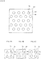
- the shape of the opening 9J may be a triangle like the hole 7J illustrated in FIG. 6A .
- the shape of the opening 9K may be a quadrangle like the hole 7K illustrated in FIG. 6B .
- the shape of the opening 9L may be a hexagon like the hole 7L illustrated in FIG. 6C .
- the shape of the opening 9 may be a pentagon, a heptagon, or a polygon with the number of vertices greater than 7.
- the openings 9 of the holes 7 may have shapes of the stars having approximately 3 to 10 points as illustrated in FIG. 7A to FIG. 7G . All the shapes of the openings 9 of the holes 7 formed in the active material layer 6 may not necessarily be identical. The openings 9 having different shapes may coexist.
- the hole 7 may have the quadrangular-shaped opening 9 and the triangular longitudinal sectional shape.
- the hole 7 has the shape of a quadrangular pyramid.
- the present invention is not limited to this; and thus, the lithium ion secondary battery having a multilayer structure, in which the cathodes 2 and the anodes 3 are further stacked through the separators 4 may be employed.
- the lithium ion secondary battery 1 A may have a multilayer structure in which the cathodes 2 and the anodes 3 are alternately stacked through the separators 4 to form a four-layer structure.
- the openings 9 of the holes 7 in one of the cathodes 2 face the openings 13 of the holes 12 in one of the anodes 3 through the separator 4.
- the lithium ion can readily migrate between the cathode 2 and the anode 3, so that the battery can be charged and discharged more efficiently.
- the lithium ion secondary battery 1B may have a multilayer structure in which the cathode 2D and the anode 3D, which has the same shape as the cathode 2D, are stacked in the manner similar to the lithium ion secondary battery 1A. Similar to the above, in the lithium ion secondary battery 1 B, at each of the separators 4, one of the opening 9D of the hole 7D in the cathode 2D, the opening 29D of the hole 27D in the cathode 2D, the opening 13D of the hole 12D in the anode 3D, and the opening 33D of the hole 32D in the anode 3D faces the separator 4, so that the battery is charged and discharged more efficiently.
- Examples (may be abbreviated as Ex.) 1 to 6 the cathode for a lithium ion secondary battery of the present invention using LCO as the active material was prepared; and the cathode was used in an electrochemical cell.
- the depths of the holes formed in the active material layer are different, but other configurations are the same. The explanation will be made with regard to the preparation method of the electrochemical cell of Example 1 by way of example.
- NMP N-methyl-2-pyrrolidone
- an aluminum foil having the thickness of 15 ⁇ m and trimmed to the size of 3 cm x 3 cm was prepared as the current collector.
- the cathode slurry was applied on one surface of the aluminum foil by using a comma roll coater (product name: Chibi Coater; manufactured by Thank Metal Co., Ltd.), and then dried at 120°C for 1 hour.
- the active material layer is formed.
- the same active material layer was formed on the other surface of the aluminum foil.
- the thickness of the active material layer thus formed is 350 ⁇ m.
- the aluminum foil having the active material layers formed on the respective surfaces was compressed by using a roll pressing machine (product name: 5-Ton Air Hydropress; manufactured by Thank Metal Co., Ltd.) such that each active material layer was compressed to the thickness of 300 ⁇ m.
- the needles closely arranged in the pinholder shape were pressed against the surface of one of the active material layers thus compressed, to form the holes having the parameters shown in Table 1.
- the needles closely arranged in the pinholder shape were pressed against the surface of the other active material layer compressed, to form a plurality of holes.
- the cathode having the active material layers on the both surfaces was prepared.
- Each active material layer included 120 mg/cm 2 of LCO with the active material density of 4.0 g/cm 3 (79% relative to the true density).
- a metal lithium foil was stamped out to obtain two counter electrodes having the same size as the prepared cathode.
- Two separators made of polyethylene having innumerable fine pores were prepared, and the cathode was disposed between the separators, and the separators having the cathode between them were disposed between the metal lithium foils.
- the cathode that was sandwiched by the separators and the metal lithium foils was inserted into an aluminum-laminated pack, together with an electrolyte solution obtained by adding 1 M LiPF 4 to a mixed solvent of EC and DEC at the volume ratio of 1:1; and then, the pack was evacuated to obtain a laminate cell.
- the laminate cell thus obtained was used as the electrochemical cell of Example 1.
- the effective area of the electrode is 9 cm 2 .
- Example 6 The electrochemical cells of Examples 2 to 6 were prepared in the same way as Example 1. In Example 6, the holes were formed concurrently in the active material layer and in the aluminum foil. Thus, the cathode having the penetrating holes is produced.
- an electrochemical cell of Comparative Example (may be abbreviated as C. Example or C. Ex.) 1 was prepared.
- the electrochemical cell of Comparative Example 1 is the same as the electrochemical cell of Example 1, except that the holes were not formed in the active material layer.
- the data of the cathodes of Example 1 to 6 and Comparative Example 1 are shown in Table 1. All the active material layers of the obtained cathodes have the same active material density as that in Example 1. [Table 1] Example 1 Example 2 Example 3 Example 4 Example 5 Example 6 C.
- Example 1 Presence of hole Yes Yes Yes Yes Yes Yes Yes Yes Yes Yes No Shape of hole's opening Circular Circular Circular Circular Circular Circular Circular Circular - Shape of hole in longitudinal sectional view Pentagonal Pentagonal Pentagonal Pentagonal Pentagonal - Maximum diameter ( ⁇ m) of holes 1000 1000 1000 1000 1000 1000 1000 - Type of active material LCO LCO LCO LCO LCO LCO LCO Multiplier of maximum diameter of holes to get holes' center-to-center distance 4 4 4 4 4 4 - Holes' center-to-center distance ( ⁇ m) 4000 4000 4000 4000 4000 4000 4000 - Thickness of active material layer ( ⁇ m) 300 300 300 300 300 300 300 300 300 300 300 300 300 300 300 300 300 300 300 300 300 300 300 300 300 300 300 300 300 300 300 300 300 300 300 300 300 300 300 300 300 300 300 300 300 300 300 300 300 300 300 300 300 300 300 300 300 300 300 300 300 300 300 300 300 300 300 300 300 300 300 300 300 300 300 300 300 300 300 300 300 300 300 300 300 300 300 300 300 300 300 300
- Example 7 the cathode for a lithium ion secondary battery using LMO as the active material was prepared and used in the electrochemical cell.
- the holes' center-to-center distances of the holes formed in the active material layer are different, but other configurations are the same. The explanation will be made with regard to the preparation method of the electrochemical cell of Example 7 by way of example.
- each of LMO, which was used as the active material, PVDF, which was used as the binder, and AB, which was used as the conduction assisting agent was weighed to achieve the mass ratio of 94 : 4 : 2. Thereafter, the weighed PVDF was added to NMP, which was used as the solvent, and the resulting mixture was stirred for 20 minutes. Further, LMO and AB were added to the resulting mixture, and the mixture was stirred and the viscosity was adjusted to 7 Pa ⁇ s. Thus, the cathode slurry was obtained.
- an aluminum foil having the thickness of 15 ⁇ m and trimmed to the size of 3 cm x 3 cm was prepared as the current collector.
- the active material layers were formed on the respective surfaces of the aluminum foil in the same way as Example 1.
- the thickness of the active material layer thus formed is 1200 ⁇ m.
- the aluminum foil having the active material layers on the respective surfaces was compressed by using a roll pressing machine such that each active material layer was compressed to the thickness of 1000 ⁇ m.
- the holes having the parameters shown in Table 2 were formed.
- the cathode having the active material layers on the respective surfaces is produced.
- the active material layer included 340 mg/cm 2 of LMO with the active material density of 3.4 g/cm 3 (81% relative to the true density).
- the electrochemical cell was prepared in the same way as Example 1.
- the electrochemical cells of Examples 8 to 12 were prepared in the same way as Example 7.
- Example 7 For comparison purpose, an electrochemical cell of Comparative Example 2 was prepared.
- the electrochemical cell of Comparative Example 2 was the same as that of Example 7, except that the holes were not formed in the active material layer.
- the data of the cathodes of Example 7 to 12 and Comparative Example 2 are shown in Table 2. All the active material layers of the cathodes prepared have the same active material density as that in Example 7. [Table 2] Example 7 Example 8 Example 9 Example 10 Example 11 Example 12 C.
- Examples 13 to 18 the cathode for a lithium ion secondary battery using the ternary cathode material as the active material was prepared, and the cathode was used in the electrochemical cell.
- the maximum diameters of the holes formed in the active material layer are different, and the methods for making the holes and the depths are different between Examples 13 to 15 and Examples 16 to 18, but other configurations are the same. The explanation will be made with regard to the preparation method of the electrochemical cell of Example 13 by way of example.
- an aluminum foil having the thickness of 15 ⁇ m and trimmed to the size of 3 cm x 3 cm was prepared as the current collector; and then, the active material layers were formed on the respective surfaces of the aluminum foil in the same way as Example 1.
- the thickness of the active material layer thus formed is 210 ⁇ m.
- the aluminum foil having the active material layers formed on both surfaces was compressed by using a roll pressing machine. Thereby, each active material layer was compressed to the thickness of 150 ⁇ m.
- the holes having the parameters shown in Table 3 were formed by a laser beam with the diameter of 5 ⁇ m with the use of a laser processing machine (product name: ML605 GTW4, manufactured by Mitsubishi Electric Corp.). At this time, the same holes penetrate the aluminum foil. Thus, the penetrating holes were formed in the cathode. Thereby, the cathode was prepared.
- the cathode includes the active material layers each including the ternary cathode material, on both surfaces.
- the active material layers include the ternary cathode material at the active material density of 3.7 g/cm 3 (80% relative to the true density) and at 18.5 mg/cm 2 .
- the electrochemical cell was prepared in the same way as Example 1.
- the holes were formed in the same way as Example 1 by using the pinholder.
- the electrochemical cells of Examples 14 to 18 were prepared in the same way as Example 13.
- Example 13 For comparison purpose, an electrochemical cell of Comparative Example 3 was prepared.
- the electrochemical cell of Comparative Example 3 is the same as that of Example 13, except that holes were not formed in the active material layer and the current collector.
- the data of the cathodes of Example 13 to 18 and Comparative Example 3 are shown in Table 3. All the active material layers of the cathodes prepared have the same active material density as that in Example 13. [Table 3] Example 13 Example 14 Example 15 Example 16 Example 17 Example 18 C.
- Examples 19 to 22 the cathode for a lithium ion secondary battery using LNO as the active material was prepared, and was used in the electrochemical cell.
- the shapes of the openings of the holes formed in the active material layer are different, but other configurations are the same. The explanation will be made with regard to the preparation method of the electrochemical cell of Example 19, by way of example.
- an aluminum foil having the thickness of 15 ⁇ m and trimmed to the size of 3 cm x 3 cm was prepared as the current collector.
- the active material layers were formed on both surfaces of the aluminum foil in the same way as Example 1.
- the thickness of the active material layer thus formed is 480 ⁇ m.
- the aluminum foil having the active material layers formed on both surfaces was compressed by using a roll pressing machine such that each active material layer was compressed to the thickness of 400 ⁇ m.
- the holes having the parameters shown in Table 4 were formed in the active material layer in the same way as Example 1 and thus the cathode was prepared.
- the cathode has the active material layers, each including LNO, on the both surfaces.
- the active material layers included LNO at the active material density of 3.8 g/cm 3 (79% relative to the true density) and at 152 mg/cm 2 .
- the electrochemical cell was prepared in the same way as Example 1.
- the electrochemical cells of Examples 20 to 22 were prepared in the same way as Example 19.
- Example 19 For comparison purpose, an electrochemical cell of Comparative Example 4 was prepared.
- the electrochemical cell of Comparative Example 4 is the same as the electrochemical cell of Example 19, except that the holes were not formed in the active material layer.
- the data of the cathodes of Example 19 to 22 and Comparative Example 4 are shown in Table 4. All the active material layers of the cathodes prepared have the same active material density as that in Example 19. [Table 4] Example 19 Example 20 Example 21 Example 22 C.
- Example 23 the cathode for a lithium ion secondary battery using LFP as the active material was prepared, and was used in the electrochemical cell.
- an aluminum foil having the thickness of 15 ⁇ m and trimmed to the size of 3 cm x 3 cm was prepared as the current collector.
- the active material layers were formed on both surfaces of the aluminum foil in the same way as Example 1.
- the thickness of the active material layer thus formed is 180 ⁇ m.
- the aluminum foil having the active material layers formed on both surfaces was compressed by using a roll pressing machine such that each active material layer was compressed to the thickness of 150 ⁇ m.
- the holes having the parameters shown in Table 5 were formed in the active material layer in the same way as Example 1.
- the cathode having the active material layers, each including LFP, on the both surfaces was prepared.
- the active material layers included LFP at the active material density of 2.88 g/cm 3 (80% relative to the true density) and at 43.2 mg/cm 2 .
- the electrochemical cell was prepared in the same way as Example 1.
- an electrochemical cell of Comparative Example 5 was prepared.
- the electrochemical cell of Comparative Example 5 is the same as the electrochemical cell of Example 23, except that the holes were not formed in the active material layers of Comparative Example 5.
- Example 24 the cathode for a lithium ion secondary battery using NCA as the active material was prepared; and this was used as the cathode for the electrochemical cell.
- an aluminum foil having the thickness of 15 ⁇ m and trimmed to the size of 3 cm x 3 cm was prepared as the current collector.
- the active material layers were formed on both surfaces of the aluminum foil in the same way as Example 1.
- the thickness of the active material layer thus formed is 620 ⁇ m.
- the aluminum foil having the active material layers formed on both surfaces was compressed by using a roll pressing machine such that each active material layer was compressed to the thickness of 500 ⁇ m.
- the holes having the parameters shown in Table 5 were formed in the active material layer in the same way as Example 1.
- the cathode having the active material layers, each including NCA, on the both surfaces was prepared.
- Each active material layer included NCA at the active material density of 3.9 g/cm 3 (80% relative to the true density) and at 195 mg/cm 2 .
- the electrochemical cell was prepared in the same way as Example 1.
- an electrochemical cell of Comparative Example 6 was prepared.
- the electrochemical cell of Comparative Example 6 was the same as the electrochemical cell of Example 24, except that the holes were not formed in the active material layers of Comparative Example 6.
- the data of the cathodes of Example 23 and 24 and the data of the cathodes of Comparative Examples 5 and 6 are shown in Table 5.
- Example 23 Example 24 Comparative Example 5 Comparative Example 6 Presence of hole Yes Yes No No Shape of hole's opening Circular Circular - - Shape of hole in longitudinal sectional view Pentagonal Pentagonal - - Maximum diameter ( ⁇ m) of holes 500 500 - - Type of active material LiFePO 4 LiNi 0.8 Co 0.15 Al 0.05 O 2 LiFePO 4 LiNi 0.8 Co 0.15 Al 0.05 O 2 Multiplier of maximum diameter of holes to get holes' center-to-center distance 4 4 - - Holes' center-to-center distance ( ⁇ m) 2000 2000 - - Thickness ( ⁇ m) of active material layer 150 500 150 500 Depth ( ⁇ m) of hole 120 450 - - Ratio (%) of depth of hole to thickness of active material layer 80 90 - - Means for forming holes Pinholder Pinholder - - Presence of penetrating hole formed in current collector No No No No Discharge capacity (mAh/cm 2 ) per area 10.2 52.6 5.5 11.2 Discharge
- Examples 25 to 29 the cathode for a lithium ion secondary battery using LCO as the active material was prepared, and was used in the electrochemical cell.
- Example 25 by using the cathode slurry having the viscosity of 4.5 Pa ⁇ s, the active material layers, each having the thickness of 230 ⁇ m, were formed on both surfaces of the aluminum foil having the thickness of 15 ⁇ m.
- the cathode shown in Table 6-1 was prepared in the same way as Example 1.
- Example 26 by using the cathode slurry having the viscosity of 4.8 Pa ⁇ s, the active material layers, each having the thickness of 235 ⁇ m, were formed on both surfaces of the aluminum foil having the thickness of 15 ⁇ m.
- the cathode shown in Table 6-1 was prepared in the same way as Example 25.
- Example 27 by using the cathode slurry having the viscosity of 5 Pa ⁇ s, the active material layers, each having the thickness of 240 ⁇ m, were formed on both surfaces of the aluminum foil having the thickness of 15 ⁇ m.
- the cathode shown in Table 6-1 was prepared in the same way as Example 25.
- Example 28 by using the cathode slurry having the viscosity of 5.5 Pa ⁇ s, the active material layers, each having the thickness of 250 ⁇ m, were formed on both surfaces of the aluminum foil having the thickness of 15 ⁇ m.
- Example 29 by using the cathode slurry having the viscosity of 5.5 Pa ⁇ s, the active material layers, each having the thickness of 260 ⁇ m, were formed on both surfaces of the aluminum foil having the thickness of 15 ⁇ m. Each of the active material layers was compressed to the thickness of 200 ⁇ m.
- the surfaces of the cathodes were irradiated with a laser beam with the diameter of 100 ⁇ m by using a laser processing machine. Thus, the cathodes shown in Table 6-1 were prepared.
- Comparative Example 7 For comparison purpose, in Comparative Example 7, by using the cathode slurry having the viscosity of 4 Pa ⁇ s, the active material layers, each having the thickness of 210 ⁇ m, were formed on both surfaces of the aluminum foil having the thickness of 15 ⁇ m.
- the cathode shown in Table 6-1 was prepared in the same way as Example 25.
- Comparative Example 8 the electrochemical cell having the same configuration as Comparative Example 7, except that there are no holes, was prepared.
- Comparative Example 9 by using the cathode slurry having the viscosity of 4 Pa ⁇ s, the active material layers, each having the thickness of 210 ⁇ m, were formed on both surfaces of the aluminum foil having the thickness of 15 ⁇ m. Each of the active material layers thus prepared was compressed to the thickness of 200 ⁇ m.
- the cathode shown in Table 6-1 was prepared in the same way as Example 25.
- Comparative Example 10 the electrochemical cell having the same configuration as Comparative Example 9, except that there are no holes, was prepared.
- Comparative Example 11 by using the cathode slurry having the viscosity of 4 Pa ⁇ s, the active material layers, each having the thickness of 220 ⁇ m, were formed on both surfaces of the aluminum foil having the thickness of 15 ⁇ m.
- the cathode shown in Table 6-2 was prepared in the same way as Example 25.
- Comparative Example 12 the electrochemical cell having the same configuration as Comparative Example 11, except that there are no holes, was prepared.
- Comparative Examples 13, 14, 15, 16, and 17 were prepared. Comparative Examples 13, 14, 15, 16, and 17 respectively have the same configuration as Examples 25, 26, 27, 28, and 29, except that there are no holes in the electrochemical cells of Comparative Examples 13, 14, 15, 16, and 17.
- the data of the cathodes of Examples 25 to 29 and Comparative Examples 7 to 17 are shown in Tables 6-1 and 6-2.
- the maximum diameter of the holes, the holes' center-to-center distance, and the depth of the hole were measured with a laser microscope (product name: VK-X100, manufactured by Keyence Corp.).
- the holes were formed in the active material layer. The values were measured at each of 30 sites, and the average value was calculated.
- the active material density was calculated in a way described below. Firstly, the cathode was trimmed to the area size of 1 cm 2 , and then, the weight and thickness were measured. Then, the aluminum foil, i.e., the current collector was removed from the cathode thus trimmed, and the weight and thickness of the aluminum foil thus removed were measured. Then, the thickness of the aluminum foil was subtracted from the thickness of the cathode (when the active material layers was formed on both surfaces of the aluminum foil, the result was divided by 2) to calculate the thickness of the active material layer. The calculated value of the thickness of the active material layer was multiplied by the area of the trimmed current collector to obtain the calculated value of the volume of the active material layer.
- the value obtained by subtracting the weight of the aluminum foil from the weight of the cathode was multiplied by the weight fraction of the electrode slurry at the time of preparation (for example, in the case of LCO in Example 1, the weight fraction was 0.93) (when the active material layer was formed on both surfaces of the aluminum foil, the result was divided by 2) to obtain the calculated value of the weight of the active material.
- the weight of the active material may be measured as following: a part (the size of 1 cm 2 ) of the cathode of the actual battery is cut out, then the current collector is removed from the cut-out piece of the cathode, then the mixed material layer including the active material is dissolved into N-methyl-2pyrrolidone (NMP) followed by centrifugal separation, thereby only the active material is separated, and then the separated active material is dried and weighed.
- NMP N-methyl-2pyrrolidone
- the weight of the active material thus obtained was divided by the volume of the active material layer, to calculate the active material density.
- the value obtained by dividing the value of the active material weight by the area of the cut-out piece of the cathode was defined as the supported amount of the active material per unit area.
- the discharge capacity per unit mass was measured to evaluate the characteristics of the electrochemical cell.
- the discharge capacity was measured by using the charging/discharging testing apparatus (model: ACD-R1APS, manufactured by Aska Electronic Co., Ltd.) at the temperature of 25 ⁇ 1°C.
- the electrochemical cell was charged with the constant current (CC: constant current) of 5 mA/cm 2 and the constant voltage (CV: constant voltage) of 4.2 V until the charging current decreased to 0.1 mA/cm 2 , and then the electrochemical cell was discharged with the constant current of 10 mA/cm 2 and the cut-off voltage of 3.0 V vs. Li/Li + , and the electric capacity obtained was defined as the discharge capacity.
- the holes are formed in the cathodes.
- the ratio of the depth of the hole relative to the thickness of the active material layer is 5% or more .
- both the discharge capacity per unit area and the discharge capacity per unit mass are higher than those of the electrochemical cell of Comparative Example 1.
- the ratio of the depth of the hole relative to the thickness of the active material layer was in a range of 67% or higher, the discharge capacities per area were 22.8 to 31.2 mAh/cm 2 , and the discharge capacities per mass were 95 to 130 mAh/g. Thus, the discharge capacities per area and the discharge capacities per mass were higher. From this, it can be seen that in the cathode for a lithium ion secondary battery of the present invention, the ratio of the depth of the hole relative to the thickness of the active material layer is more preferably 67% or more.
- the electrochemical cell of Example 5 has the holes.
- the holes penetrate the active material layer and have the bottom portions formed by (included in) the aluminum foil.
- the electrochemical cell of Example 6 has the penetrating holes that penetrate the aluminum foil and the active material layer.
- the difference between them resides in whether the penetrating holes are formed in the aluminum foil.
- the values of the discharge capacities are the same. Thus, the cell performance is not decreased even when the penetrating holes are formed in the aluminum foil.
- the holes are formed in the cathode with the holes' center-to-center distance of 500 to 8000 ⁇ m. Both the discharge capacities per area and the discharge capacities per mass of the electrochemical cells of Examples 7 to 12 are higher than those of the electrochemical cell of Comparative Example 2.
- the holes' center-to-center distance is in the range of 500 to 4000 ⁇ m
- the discharge capacities per area was 77.5 to 86.4 mAh/cm 2
- the discharge capacities per mass was 114 to 127 mAh/g.
- the discharge capacities per area and the discharge capacities per mass are higher. From this, it can be seen that in the cathode for a lithium ion secondary battery of the present invention, the holes' center-to-center distance is more preferably 500 to 4000 ⁇ m.
- the maximum diameter of the holes is in the range of 500 to 2000 ⁇ m
- the discharge capacities per area were 10.7 to 13.8 mAh/cm 2
- the discharge capacities per mass were 97 to 125 mAh/g.
- the discharge capacities per area and the discharge capacities per mass are higher. From this, it can be seen that in the cathode for a lithium ion secondary battery of the present invention, the maximum diameter of the holes is particularly preferably 500 to 2000 ⁇ m.
- both the discharge capacity per area and the discharge capacity per mass of the electrochemical cell of Example 23 are higher than those of Comparative Example 5, and both the discharge capacity per area and the discharge capacity per mass of the electrochemical cell of Example 24 are higher than those of Comparative Example 6.
- the electrochemical cells of Examples in which any of LCO, LMO, ternary cathode material, and LNO is used as the active material have higher discharge capacities as compared with the corresponding Comparative Examples not having the holes formed in the cathode.
- the discharge capacity is improved by using any of LCO, LMN, the ternary cathode material, LNO, LFP, and NCA as the active material.
- the relationship between the active material density of the active material layer of the cathode and the discharge capacity of the electrochemical cell using this cathode is shown in Tables 6-1 and 6-2.
- the discharge capacity per electrochemical cell was used as the value of discharge capacity.
- LCO was used as the active material.
- the electrochemical cells of Examples 25 to 29 have higher discharge capacities than those of the electrochemical cells of Comparative Examples 7 to 17.
- Example 25 When Example 25 is compared with Comparative Example 13, which is different from Example 25 only in that the holes were not formed, the discharge capacity in Example 25 is significantly higher than that of Comparative Example 13 by 78 mAh due to the holes.
- Comparative Example 7 when Comparative Example 7 is compared with Comparative Example 8, which is different from Comparative Example 7 only in that the holes were not formed, the discharge capacity of Comparative Example 7 is higher than that of Comparative Example 8 only by 6 mAh, despite that the same holes as those in Example 25 are formed in the cathode of Comparative Example 7.
- the discharge capacity of Comparative Example 9 is higher than that of Comparative Example 10 by 46 mAh
- the discharge capacity of Comparative Example 11 is higher than that of Comparative Example 12 by 54 mAh.
- the increases in the discharge capacities are small as compared with the case of Example 25.
- the active material density of the cathode is low, i.e., 53% relative to the true density of the active material, so that more voids are formed correspondingly. Because of this, the cathode includes sufficient amount of the electrolyte solution even though the holes are not formed in the cathode. Thus, the active material that is present in the position deep in the thickness direction from the surface can be effectively utilized. Accordingly, it is considered that the active material that can be utilized effectively is not increased so much even when the holes are formed in the cathode. Hence, the increase in the discharge capacity is small.
- the ratio of the active material density relative to the true density is so low that the cathodes include sufficient amount of the electrolyte solution, and thus, the active material that can be utilized effectively is so small that the increase in the discharge capacity is small.
- Comparative Example 13 because the active material density is high, i.e., 68% relative to the true density, the amount of the electrolyte solution included in the cathode was insufficient. Hence, the active material that was present in the position deep in the thickness direction from the surface could not be effectively utilized.
- the electrolyte solution is present also in the holes, and the lithium ion can reach the position deep in the thickness direction from the surface, and the active material that can be effectively utilized is increased, and the discharge capacity in the cathode is increased. This is supported by the finding that an amount of the discharge capacity increased by the formation of the holes increases with the increase in the active material density.
- the ratio of the active material density relative to the true density is in the range of 68 to 83%, the discharge capacity is significantly increased due to formation of the holes, and it can be seen that the increase in the discharge capacity due to formation of the holes is large as compared with Comparative Examples 7, 9, and 11.
- the ratio of the active material density relative to the true density is 70% or higher, the discharge capacity is increased by 2-folds or more due to formation of the holes, so that more significant increase in the discharge capacity is achieved.
- the ratio of the active material density relative to the true density is 73% or higher, it can be seen that increase in the discharge capacity due to formation of the holes is much larger even as compared with Examples 25 and 26.
- the discharge capacity is increased with the increase in the active material density.
- the reason for this is considered as follows.
- the active material supported by the cathode is increased with the increase in the active material density.
- the lithium ion reaches the active material that is present in the position deep in the thickness direction from the surface.
- the active material that can be effectively utilized is increased.
- the lithium ion can migrate through the electrolyte solution that is present in the holes to the position of the cathode far from the separator, and then the lithium ion penetrates in the horizontal direction of the holes. It is considered that because of this, even in the position deep in the thickness direction from the surface, the lithium ion can be transferred, so that a high discharge capacity is obtained. It is considered that the cathode supports more amount of the active material with the increase in the active material density, so that the active material that can be effectively utilized is increased. Hence, a high discharge capacity is achieved.
- the amount of the electrolyte solution to be impregnated in the cathode can be reduced.
- the active material density is 79%; and in the remaining 21%, voids, PVDF, and AB are included.
- the cathode is composed of 95% by weight of LCO, 3% by weight of PVDF, and 2% by weight of AB.
- the volume that is occupied by PVDF and AB in the cathode is approximately 13%. Consequently, the void ratio is approximately 8%.
- the active material density of the cathode of Comparative Example 7 is 53%. Therefore, with the use of calculation similar to the above, the volume occupied by PVDF and AB is approximately 13%. Accordingly, the void ratio is approximately 34%.
- the cathode for a lithium ion secondary battery of the present invention can reduce the amount of the electrolyte solution to be used; and in addition, the discharge capacity per volume is high and charge and discharge can be performed promptly.
- the electrochemical cells of Examples 30 to 59 were prepared.
- the active material densities of the cathodes of the present invention were varied in the range of 68 to 83% relative to the true density; and the electrochemical cells similar to the above were prepared by using the cathodes.
- the ternary cathode material Li(Ni 1/3 Mn 1/3 Co 1/3 )O 2
- the active material of the cathode had the same shape: the shape of the opening of the hole was a star (5 points); the longitudinal sectional shape of the hole was a U-shape; the maximum diameter of the hole was 500 ⁇ m; the holes' center-to-center distance was 2000 ⁇ m; and the depth of the hole was 120 ⁇ m (the ratio of the depth of the hole relative to the thickness of the active material layer was 80%).
- Comparative Examples 18, 20, and 26 the cathodes having the same holes as the Examples while having the active material density of 50%, 60%, and 85%, respectively, relative to the true density were prepared; in Comparative Example 19, the cathode without having the holes while having the same active material density as the cathode of Comparative Example 18 was prepared.
- Comparative Example 21 the cathode without having the holes while having the same active material density as the cathode of Comparative Example 20 was prepared; and in Comparative Examples 22 to 25, the cathodes without having the holes while having the same active material densities as the cathodes of Examples 30 to 33 were respectively prepared; and by using the cathodes, respective electrochemical cells were prepared.
- the electrochemical cells were prepared in the same way as Example 1.
- Example 30 to 34 and Comparative Examples 18 to 26 the electrochemical cell was charged with the charging current of 1mA/cm 2 and the constant voltage of 4.20 V until the charging current decreased to 0.1 mA/cm 2 . Then, this was discharged with the cut-off voltage of 3.0 V vs. Li/Li + and the discharging current of 5 mA/cm 2 to obtain the measured discharge capacity. In the first discharging, 10 mAh/cm 2 of discharge was carried out.
- LMO was used as the active material, and all the holes formed in the active material of the cathode had the same shape: the shape of the opening of the hole was a quadrangle; the longitudinal sectional shape of the hole was a pentagon; the maximum diameter of the hole was 1000 ⁇ m; the holes' center-to-center distance was 4000 ⁇ m; and the depth of the hole was 180 ⁇ m (the ratio of the depth of the hole relative to the thickness of the active material layer was 90%).
- Comparative Examples 27, 29, and 35 the cathodes having the same holes as the Examples while having the active material density of 50%, 60%, and 85%, respectively, relative to the true density were prepared; in Comparative Example 28, the cathode without having the holes while having the same active material density as the cathode of Comparative Example 27 was prepared; in Comparative Example 30, the cathode without having the holes while having the same active material density as the cathode of Comparative Example 29 was prepared; and in Comparative Examples 31 to 34, the cathodes without having the holes while having the same active material densities as the cathodes of Examples 35 to 38 were respectively prepared; and by using the cathodes, respective electrochemical cells were prepared. The electrochemical cells were prepared in the same way as Example 1.
- Example 35 to 39 and Comparative Examples 27 to 35 the electrochemical cell was charged with the charging current of 1mA/cm 2 and the constant voltage of 4.35 V until the charging current decreased to 0.1 mA/cm 2 . Then, this was discharged with the cut-off voltage of 3.0 V vs. Li/Li + and the discharging current of 5 mA/cm 2 to obtain the measured discharge capacity. In the first discharging, 10 mAh/cm 2 of discharge was carried out.
- LNO was used as the active material, and all the holes formed in the active material of the cathode had the same shape: the shape of the opening of the hole was a circle (round shape); the longitudinal sectional shape of the hole was a pentagon; the maximum diameter of the hole was 1000 ⁇ m; the holes' center-to-center distance was 3000 ⁇ m; and the depth of the hole was 143 ⁇ m (the ratio of the depth of the hole relative to the thickness of the active material layer was 95%).
- Comparative Examples 36, 38, and 44 the cathodes having the same holes as the Examples while having the active material density of 50%, 60%, and 85%, respectively, relative to the true density were prepared; in Comparative Example 37, the cathode without having the holes while having the same active material density as the cathode of Comparative Example 36 was prepared; in Comparative Example 39, the cathode without having the holes while having the same active material density as the cathode of Comparative Example 38 was prepared; and in Comparative Examples 40 to 43, the cathodes without having the holes while having the same active material densities as the cathodes of Examples 40 to 43 were respectively prepared; and by using the cathodes, respective electrochemical cells were prepared.
- the electrochemical cells were prepared in the same way as Example 1.
- the electrochemical cell was charged with the charging current of 1mA/cm 2 and the constant voltage of 4.40 V until the charging current decreased to 0.1 mA/cm 2 .
- the electrochemical cell was discharged with the cut-off voltage of 3.0 V vs. Li/Li + and the discharging current of 5 mA/cm 2 to obtain the measured discharge capacity.
- 5 mAh/cm 2 of discharge was carried out.
- NCA was used as the active material, and all the holes formed in the active material of the cathode had the same shape: the shape of the opening of the hole was a hexagon; the longitudinal sectional shape of the hole was a U-shape; the maximum diameter of the hole was 800 ⁇ m; the holes' center-to-center distance was 2500 ⁇ m; and the depth of the hole was 162 ⁇ m (the ratio of the depth of the hole relative to the thickness of the active material layer was 90%).
- Comparative Examples 45, 47, and 53 the cathodes having the same holes as the Examples while having the active material density of 50%, 60%, and 85%, respectively, relative to the true density were prepared; in Comparative Example 46, the cathode without having the holes while having the same active material density as the cathode of Comparative Example 45 was prepared; in Comparative Example 48, the cathode without having the holes while having the same active material density as the cathode of Comparative Example 47 was prepared; and in Comparative Examples 49 to 52, the cathodes without having the holes while having the same active material densities as the cathodes of Examples 45 to 48 were respectively prepared; and by using the cathodes, respective electrochemical cells were prepared.
- the electrochemical cells were prepared in the same way as Example 1.
- the electrochemical cell was charged with the charging current of 1mA/cm 2 and the constant voltage of 4.40 V until the charging current decreased to 0.1 mA/cm 2 . Then, this was discharged with the cut-off voltage of 3.0 V vs. Li/Li + and the discharging current of 5 mA/cm 2 to obtain the measured discharge capacity. In the first discharging, 5 mAh/cm 2 of discharge was carried out.
- LFP was used as the active material, and all the holes formed in the active material of the cathode had the same shape: the shape of the opening of the hole was a circle (round shape), the longitudinal sectional shape of the holes was a quadrangle, the maximum diameter of the hole was 100 ⁇ m, the holes' center-to-center distance was 1000 ⁇ m, and the depth of the hole was 150 ⁇ m (the ratio of the depth of the hole relative to the thickness of the active material layer was 100%).
- the holes are penetrating holes that penetrate through the current collector of the cathode.
- Comparative Examples 54, 56, and 62 the cathodes having the same holes as the Examples while having the active material density of 50%, 60%, and 85%, respectively, relative to the true density were prepared; in Comparative Example 55, the cathode without having the holes while having the same active material density as the cathode of Comparative Example 54 was prepared; in Comparative Example 57, the cathode without having the holes while having the same active material density as the cathode of Comparative Example 56 was prepared; and in Comparative Examples 58 to 61, the cathodes without having the holes while having the same active material densities as the cathodes of Examples 50 to 53 were respectively prepared; and by using the cathodes, respective electrochemical cells were prepared.
- the electrochemical cells were prepared in the same way as Example 1.
- the electrochemical cell was charged with the charging current of 1mA/cm 2 and the constant voltage of 3.70 V until the charging current decreased to 0.1 mA/cm 2 .
- the electrochemical cell was discharged with the cut-off voltage of 2.5 V vs. Li/Li + and the discharging current of 5 mA/cm 2 to obtain the measured discharge capacity. In the first discharging, 5 mAh/cm 2 of discharge was carried out.
- the active material layer including 80% by weight of LCO and 20% by weight of LFP as the active material was used, and all the holes formed in the active material of the cathode had the same shape: the shape of the opening of the hole was a circle (round shape), the longitudinal sectional shape of the hole was a quadrangle, the maximum diameter of the hole was 500 ⁇ m, the holes' center-to-center distance was 4000 ⁇ m, and the depth of the hole was 190 ⁇ m (the ratio of the depth of the hole relative to the thickness of the active material layer was 95%).
- Comparative Examples 63, 65, and 71 the cathodes having the same holes as the Examples while having the active material density of 50%, 60%, and 85%, respectively, relative to the true density were prepared; in Comparative Example 64, the cathode without having the holes while having the same active material density as the cathode of Comparative Example 63 was prepared; in Comparative Example 66, the cathode without having the holes while having the same active material density as the cathode of Comparative Example 65 was prepared; and in Comparative Examples 67 to 70, the cathodes without having the holes while having the same active material densities as the cathodes of Examples 55 to 58 were respectively prepared; and by using the cathodes, respective electrochemical cells were prepared.
- the electrochemical cells were prepared in the same way as Example 1.
- the electrochemical cell was charged with the charging current of 1mA/cm 2 and the constant voltage of 4.20 V until the charging current decreased to 0.1 mA/cm 2 . Then, this was discharged with the cut-off voltage of 2.5 V vs. Li/Li + and the discharging current of 5 mA/cm 2 to obtain the measured discharge capacity. In the first discharging, 5 mAh/cm 2 of discharge was carried out.
- Ternary cathode 50 2.3 150 34.5 5.2 No 1 5 150 5.2 100 C.
- Ternary cathode 60 2.76 150 41.4 6.2 Yes 1 5 150 6.2 100 C.
- Ternary cathode 60 2.76 150 41.4 6.2 No 1 5 141 5.8 94 C.
- Ternary cathode 68 3.12 150 46.8 7.0 No 1 5 105 4.9 70 C.
- the discharge capacities per mass are approximately 1.00 fold and approximately 1.06 folds, respectively, indicating that the discharge capacity is hardly increased by forming the holes in the active material layer.
- the discharge capacity per mass is approximately 1.33 folds as compared with the electrochemical cell having the cathode which does not have the holes formed in the active material layer wherein the ratio of the active material density relative to the true density is the same as the above-mentioned, suggesting that this increase in the discharge capacity is caused by formation of the holes.
- the increase in the discharge capacity per mass due to the formation of the holes becomes much more significant when the ratio of the active material density relative to the true density is 68% or more.
- the active material supported by the active material layer can be effectively utilized so that the active material that can be effectively utilized only after the formation of the holes is so small that the discharge capacities per mass are not significantly increased by formation of the holes.
- the active material that can be effectively utilized only after the formation of the holes is so large that the discharge capacity per mass is significantly increased by the formation of the holes in the active material layer.
- the discharge capacity per mass of the electrochemical cell having the cathode which has the holes formed in the active material layer is approximately 1.35 folds when the ratio of the active material density relative to the true density is 70%, approximately 1.40 folds when the ratio of the active material density relative to the true density is 73%, and approximately 1.53 folds when the ratio of the active material density relative to the true density is 80%; and thus, the discharge capacity is increased as the ratio of the active material density relative to the true density becomes higher.
- the electrochemical cells in which the cathodes having the holes formed in the active material layer that supports LMO as the active material are used are respectively compared with the electrochemical cells in which the cathodes not having the holes while supporting the same active material and having the same active material density as those of the foregoing electrochemical cells.
- the discharge capacities per mass are increased by approximately 1.00 fold, approximately 1.05 folds, approximately 1.24 folds, approximately 1.29 folds, approximately 1.40 folds, and approximately 1.66 folds, respectively, showing the same tendency as the case in which the ternary cathode material is used as the active material.
- the electrochemical cells in which the cathodes having the holes formed in the active material layer that supports LNO as the active material are used are respectively compared with the electrochemical cells in which the cathodes not having the holes while supporting the same active material and having the same active material density as those of the foregoing electrochemical cell.
- the discharge capacities per mass are increased by approximately 1.00 fold, approximately 1.04 folds, approximately 1.24 folds, approximately 1.29 folds, approximately 1.47 folds, and approximately 1.66 folds, respectively, showing the same tendency as the case in which the ternary cathode material is used as the active material.
- the electrochemical cells in which the cathodes having the holes formed in the active material layer that supports NCA as the active material are used are respectively compared with the electrochemical cells in which the cathodes not having the holes while supporting the same active material and having the same active material density as those of the foregoing electrochemical cell.
- the discharge capacities per mass are increased by approximately 1.00 fold, approximately 1.10 folds, approximately 1.21 folds, approximately 1.28 folds, approximately 1.45 folds, and approximately 1.62 folds, respectively, showing the same tendency as the case in which the ternary cathode material is used as the active material.
- the electrochemical cells in which the cathodes having the holes formed in the active material layer that supports LFP as the active material are used are respectively compared with the cathodes not having the holes while supporting the same active material and having the same active material density as those of the foregoing electrochemical cell.
- the discharge capacities per mass are increased by approximately 1.00 fold, approximately 1.09 folds, approximately 1.28 folds, approximately 1.33 folds, approximately 1.40 folds, and approximately 1.59 folds, respectively, showing the same tendency as the case in which the ternary cathode material is used as the active material.
- the electrochemical cells in which the cathodes having the holes formed in the active material layer that supports a mixture of LCO and LFP as the active material are used are respectively compared with the electrochemical cells in which the cathodes not having the holes while supporting the same active materials and having the same active material density as those of the foregoing electrochemical cell.
- the discharge capacities per mass are increased by approximately 1.00 fold, approximately 1.10 folds, approximately 1.28 folds, approximately 1.32 folds, approximately 1.39 folds, and approximately 1.46 folds, respectively, showing the same tendency as the case in which the ternary cathode material is used as the active material.
- the discharge capacity per mass is significantly increased. Namely, when the ratio is 70% or more, the discharge capacity per mass is increased by approximately 30% or more, and when the ratio is 73% or more, the discharge capacity per mass is increased by approximately 40% or more; and thus, it can be seen that with increase in the ratio of the active material density relative to the true density, an increase in the discharge capacity per mass becomes more enhanced.
- Example 33 in which the ratio of the active material density relative to the true density is 80%
- Example 34 in which the ratio of the active material density relative to the true density is 83%
- Comparative Example 26 in which the ratio of the active material density relative to the true density is 85%
- the ternary cathode material is supported as the active material and the holes are formed in the active material layer.
- the active material density is very high so that not only the void that is present in the active material is not many but also the size thereof is small. Because of this, it is considered that in the cathode of Comparative Example 26, the amount of the electrolyte solution that is present inside the cathode is small and the void that is present among the active materials is not many; and thus, the migration resistance of the lithium ion becomes very high.
- the active material even if the holes are formed in the active material layer, the active material only in the part that is exposed to the inner space of the holes can be utilized, and the active material that is present inside the active material layer cannot be effectively utilized, so that the decrease in the value of the discharge capacity per mass is so significant.
- the ratio of the active material density relative to the true density is 83% or higher, even if the supported amount of the active material is increased by increasing the active material density, the active material that cannot be effectively utilized increases even if the holes are formed, thereby leading to drastic decrease in the discharge capacity per mass; and as a result of it, the capacity of the battery is significantly decreased.
- the ratio of the active material density relative to the true density is 68 to 83%, the active material that cannot be effectively utilized when the holes are not formed can be effectively utilized by formation of the holes.
- the ratio of the active material density relative to the true density is preferably 70 to 83%, more preferably 73 to 83%.
- the cathodes of the present invention were prepared by changing the thicknesses of the active material layers from 150 to 1000 ⁇ m; and the electrochemical cells were prepared by using the cathodes.
- the active material layer including LCO as the active material with the active material density of 68% relative to the true density was used; and all the holes formed in the active material of the cathode had the same shape: the shape of the opening of the hole was a circle (round shape), the longitudinal sectional shape of the hole was a triangle, the maximum diameter of the hole was 1000 ⁇ m, the holes' center-to-center distance was 3000 ⁇ m, and the ratio of the depth of the hole relative to the thickness of the active material layer was 90%.
- Comparative Examples 73, 75 to 79, and 81 the cathodes as same as those of Examples 60 to 63, and Comparative Examples 72, 74, and 80, except that the holes were not formed, were prepared.
- the electrochemical cells were prepared.
- the electrochemical cells were prepared in the same way as Example 1.
- the discharge capacities of these electrochemical cells were measured as follows. Each cell was charged with the charging current of 1 mA/cm 2 and the constant voltage of 4.2 V vs. Li/Li + until the charging current decreased to 0.1 mA/cm 2 , and then, discharged with the cut-off voltage of 3.0 V vs. Li/Li + and the discharging current of 5 mA/cm 2 .
- Example 72 LCO 68 3.45 50 17.2 2.5 Yes 45 90 1 5 141 2.4 97 C.
- Example 73 LCO 68 3.45 50 17.2 2.5 No - - 1 5 132 2.3 91 C.
- Example 74 LCO 68 3.45 100 34.5 5.0 Yes 90 90 1 5 136 4.7 93 C.
- Example 75 LCO 68 3.45 100 34.5 5.0 No - - 1 5 98 3.4 67 C.
- Example 76 LCO 68 3.45 150 51.8 17.5 No - - 1 5 91 4.7 62 C.
- Example 77 LCO 68 3.45 200 69.0 10.0 No - - 1 5 87 6.0 60 C.
- Example 78 LCO 68 3.45 500 172.0 25.0 No - - 1 5 68 12.0 47 C.
- Example 79 LCO 68 3.45 1000 345.0 50.0 No - - 1 5 25 8.6 36 C.
- Example 80 LCO 68 3.45 1200 414.0 60.0 Yes 1080 90 1 5 65 27.0 45 C.
- Example 81 LCO 68 3.45 1200 414.0 60.0 No - - 1 5 21 8.7 35
- both the discharge capacity per mass and the discharge capacity per area are higher than those of respective electrochemical cells of Comparative Examples 76 to 79 in which the thicknesses of the active material layers are the same as those of the Examples except that the electrochemical cells of Comparative Examples 76 to 79 do not have the holes; and thus, it can be seen that the discharge capacities are increased by formation of the holes.
- the electrochemical cells having the active material layer formed with the holes are compared with respective electrochemical cells having the active material layer not formed with the holes.
- the electrochemical cells to be compared have the active material layers with same thickness.
- the discharge capacities per mass are increased by approximately 1.07 folds, approximately 1.39 folds, approximately 1.45 folds, approximately 1.47 folds, approximately 1.62 folds, approximately 3.44 folds, and approximately 3.10 folds, respectively, by the formation of the holes.
- the amount of increase in the discharge capacity due to the formation of the holes in the active material layer is small. It is considered that in the case of a thin active material layer, the lithium ion in the electrolyte solution can be readily reach the active material that is present inside the active material layer, so that many active materials can be effectively utilized even if the holes are not formed. Because of this, it is considered that in the cathode having a thin active material layer, the active material that can be utilized only after the formation of the holes in the active material layer is so small that the increase in the discharge capacity is also small.
- the thickness of the active material layer is 150 ⁇ m or more
- the discharge capacity per mass increases significantly, as much as approximately 50% or more.
- the thickness of the active material layer is 500 ⁇ m or more
- the discharge capacity per mass increases more significantly, as much as approximately 60% or more.
- the amount of the increase in the discharge capacity per mass increases.
- the migration resistance of the lithium ion is high because the lithium ion migrates a long distance in the voids of the active material layer.
- the electrochemical cell cannot effectively utilize the active material that is present in the position deep in the thickness direction from the surface of the active material layer, so that the discharge capacity per mass is especially small.
- the lithium ion preferentially passes through the electrolyte solution that is present in the holes so that migration of the lithium ion is facilitated, thereby lowering the migration resistance.
- the active material that is present in the position deep in the thickness direction from the surface of the active material layer, which could not be utilized without the formation of the holes, is effectively utilized. As a result, the discharge capacity per mass is increased.
- the electrochemical cell of the cathode having the active material layer formed with the holes and having the thickness of 1000 ⁇ m is compared with the electrochemical cell of the cathode having the active material layer formed with the holes and having the thickness of 1200 ⁇ m.
- the discharge capacity per mass is significantly decreased and the discharge capacity per area is slightly decreased, despite that the thickness of the active material layer is increased so that the supported amount of the active material is increased as compared with the electrochemical cell of the cathode having the active material layer with the thickness of 1000 ⁇ m.
- the amount of increase in the discharge capacity per mass due to the formation of the holes is decreased as compared with the electrochemical cell of the cathode having the active material layer with the thickness of 1000 ⁇ m.
- the active material layer of the electrochemical cell of the cathode having the active material layer with the thickness of 1200 ⁇ m is thick.
- the active material layer becomes thicker, even when the lithium ion migrates in the electrolyte solution in the holes, the migration distance of the lithium ion becomes longer. Because of this, it is considered that the electrochemical cell of the cathode having the active material layer with the thickness of 1200 ⁇ m cannot carry out the cell reaction efficiently as compared with the electrochemical cell of the cathode having the active material layer with the thickness of 1000 ⁇ m, so that the discharge capacity per mass is significantly decreased and the discharge capacity per area is also decreased, thereby the amount of increase in the discharge capacity per mass due to formation of the holes is decreased.
- the thickness of the active material layer is 150 to 1000 ⁇ m
- formation of the holes allows the cathode for a secondary battery of the present invention to effectively utilize the active material which was not effectively utilized when the holes were not formed.
- the discharge capacity is increased.
- the thickness of the active material layer is more preferably 500 to 1000 ⁇ m.
Landscapes
- Chemical & Material Sciences (AREA)
- Chemical Kinetics & Catalysis (AREA)
- Electrochemistry (AREA)
- General Chemical & Material Sciences (AREA)
- Inorganic Chemistry (AREA)
- Engineering & Computer Science (AREA)
- Materials Engineering (AREA)
- Composite Materials (AREA)
- Manufacturing & Machinery (AREA)
- Crystallography & Structural Chemistry (AREA)
- Battery Electrode And Active Subsutance (AREA)
Applications Claiming Priority (3)
| Application Number | Priority Date | Filing Date | Title |
|---|---|---|---|
| JP2014184153 | 2014-09-10 | ||
| JP2015107685A JP5983821B2 (ja) | 2014-09-10 | 2015-05-27 | リチウムイオン二次電池用正極及びリチウムイオン二次電池 |
| PCT/JP2015/075193 WO2016039264A1 (fr) | 2014-09-10 | 2015-09-04 | Électrode positive pour cellule secondaire au lithium-ion et, cellule secondaire au lithium-ion |
Publications (2)
| Publication Number | Publication Date |
|---|---|
| EP3193392A1 true EP3193392A1 (fr) | 2017-07-19 |
| EP3193392A4 EP3193392A4 (fr) | 2018-03-07 |
Family
ID=55758947
Family Applications (1)
| Application Number | Title | Priority Date | Filing Date |
|---|---|---|---|
| EP15840381.6A Withdrawn EP3193392A4 (fr) | 2014-09-10 | 2015-09-04 | Électrode positive pour cellule secondaire au lithium-ion et, cellule secondaire au lithium-ion |
Country Status (6)
| Country | Link |
|---|---|
| US (1) | US20170263933A1 (fr) |
| EP (1) | EP3193392A4 (fr) |
| JP (1) | JP5983821B2 (fr) |
| KR (1) | KR20170052592A (fr) |
| CN (1) | CN106688126A (fr) |
| TW (1) | TW201630232A (fr) |
Cited By (8)
| Publication number | Priority date | Publication date | Assignee | Title |
|---|---|---|---|---|
| EP3370280A4 (fr) * | 2016-08-25 | 2018-12-05 | LG Chem, Ltd. | Électrode pour batterie secondaire comprenant des trous fins |
| EP3709321A3 (fr) * | 2019-03-15 | 2021-01-20 | BIOTRONIK SE & Co. KG | Élément d'électrode pour un condensateur, condensateur et procédé de production de l'élément d'électrode |
| WO2022196815A1 (fr) * | 2021-03-19 | 2022-09-22 | Sekisui Chemical Co., Ltd. | Électrode positive pour batterie secondaire à électrolyte non aqueux, batterie secondaire à électrolyte non aqueux, module de batterie et système de batterie utilisant ceux-ci |
| EP4057385A3 (fr) * | 2021-03-09 | 2022-10-12 | Samsung Electronics Co., Ltd. | Structure d'électrode, batterie secondaire la comprenant, et procédé de fabrication de la structure d'électrode |
| EP4125144A3 (fr) * | 2021-07-28 | 2023-03-15 | Samsung SDI Co., Ltd. | Électrode, batterie au lithium contenant l'électrode et son procédé de préparation |
| EP4535444A4 (fr) * | 2022-06-30 | 2025-10-01 | Ningde Amperex Technology Ltd | Appareil électrochimique et dispositif électronique |
| EP4693429A1 (fr) * | 2024-08-09 | 2026-02-11 | Samsung Sdi Co., Ltd. | Électrode positive pour batterie au lithium rechargeable, son procédé de fabrication et batterie au lithium rechargeable la comprenant |
| US12620573B2 (en) | 2021-07-28 | 2026-05-05 | Samsung Sdi Co., Ltd. | Electrode including electrode active material having through-holes, lithium battery containing the same, and method of preparing the same |
Families Citing this family (18)
| Publication number | Priority date | Publication date | Assignee | Title |
|---|---|---|---|---|
| TWI622214B (zh) * | 2016-09-22 | 2018-04-21 | 財團法人工業技術研究院 | 金屬離子二次電池 |
| KR102425003B1 (ko) * | 2017-02-02 | 2022-07-22 | 삼성에스디아이 주식회사 | 리튬 이차 전지 |
| JP7133301B2 (ja) * | 2017-10-10 | 2022-09-08 | 日産自動車株式会社 | 非水電解質二次電池用電極 |
| CN109037590A (zh) * | 2018-07-24 | 2018-12-18 | 安普瑞斯(无锡)有限公司 | 一种打孔锂离子电池极片和锂离子二次电池 |
| US20210050599A1 (en) * | 2019-08-16 | 2021-02-18 | Samsung Sdi Co., Ltd. | High loading electrodes having high areal capacity and energy storage devices including the same |
| JP7315726B2 (ja) * | 2019-09-24 | 2023-07-26 | エルジー エナジー ソリューション リミテッド | パターンが形成されたリチウム‐硫黄二次電池用正極、この製造方法及びこれを含むリチウム‐硫黄二次電池 |
| WO2022196831A1 (fr) | 2021-03-19 | 2022-09-22 | Sekisui Chemical Co., Ltd. | Électrode positive pour batterie secondaire à électrolyte non aqueux, et batterie secondaire à électrolyte non aqueux, module de batterie et système de batterie l'utilisant |
| JP7212130B2 (ja) * | 2021-03-19 | 2023-01-24 | 積水化学工業株式会社 | 折り曲げ使用可能な非水電解質二次電池用の正極、並びにこれを用いた非水電解質二次電池、電池モジュール、及び電池システム |
| CN113285053A (zh) * | 2021-05-06 | 2021-08-20 | 路华置富电子(深圳)有限公司 | 负极片及其制造方法、电池 |
| CN113285052A (zh) * | 2021-05-06 | 2021-08-20 | 路华置富电子(深圳)有限公司 | 正极片及其制造方法、电池 |
| CN114497457A (zh) * | 2021-12-11 | 2022-05-13 | 上海兰钧新能源科技有限公司 | 一种基于激光打孔的电芯极片及电池 |
| US12567656B1 (en) | 2022-02-11 | 2026-03-03 | Greatbatch Ltd. | Method for making a miniature electrochemical cell having lithium swaged onto the innter surface of a casing |
| US20230261173A1 (en) * | 2022-02-16 | 2023-08-17 | GM Global Technology Operations LLC | Lithium metal anodes for use in electrochemical cell and methods of making the same |
| CN117203784B (zh) * | 2022-04-07 | 2025-11-11 | 宁德时代新能源科技股份有限公司 | 电极组件以及包含其的二次电池、电池模块、电池包及用电装置 |
| CN121586957A (zh) * | 2023-07-27 | 2026-02-27 | 提升材料德国有限公司 | 用于预锂化和锂金属阳极制造的激光活化的转移工艺 |
| CN117154010A (zh) * | 2023-09-12 | 2023-12-01 | 浙江锂威能源科技有限公司 | 极片、电池及极片的制备方法 |
| CN116995188A (zh) * | 2023-09-25 | 2023-11-03 | 惠州锂威新能源科技有限公司 | 一种极片及电芯 |
| WO2025084806A1 (fr) * | 2023-10-20 | 2025-04-24 | 주식회사 엘지에너지솔루션 | Procédé de fabrication d'électrode pour batterie secondaire au lithium, électrode fabriquée selon ce procédé et batterie secondaire au lithium comprenant une électrode |
Family Cites Families (9)
| Publication number | Priority date | Publication date | Assignee | Title |
|---|---|---|---|---|
| JPH0298914A (ja) * | 1988-10-05 | 1990-04-11 | Hitachi Condenser Co Ltd | 電気二重層コンデンサ |
| JPH10326628A (ja) * | 1997-05-26 | 1998-12-08 | Mitsubishi Electric Corp | 電池およびその製造方法 |
| JP2007250510A (ja) * | 2006-02-15 | 2007-09-27 | Sanyo Electric Co Ltd | リチウム二次電池用電極及びリチウム二次電池 |
| JP2009004285A (ja) * | 2007-06-25 | 2009-01-08 | Sanyo Electric Co Ltd | 正極活物質、正極活物質の製造方法および非水電解質二次電池 |
| CN101847747A (zh) * | 2010-05-12 | 2010-09-29 | 清华大学 | 锂离子电池组 |
| JP5634372B2 (ja) * | 2010-11-04 | 2014-12-03 | 三菱電機株式会社 | 電力貯蔵デバイスセル |
| JP5730538B2 (ja) * | 2010-11-04 | 2015-06-10 | トヨタ自動車株式会社 | リチウム二次電池電極用焼結体、当該焼結体を含むリチウム二次電池用電極、及び当該電極を備えるリチウム二次電池 |
| JP2012190625A (ja) * | 2011-03-10 | 2012-10-04 | Hitachi Ltd | 非水二次電池 |
| JP2012199097A (ja) * | 2011-03-22 | 2012-10-18 | Toyota Motor Corp | 焼結型正極、及び当該焼結型正極を備える電池 |
-
2015
- 2015-05-27 JP JP2015107685A patent/JP5983821B2/ja not_active Expired - Fee Related
- 2015-08-14 TW TW104126545A patent/TW201630232A/zh unknown
- 2015-09-04 US US15/510,417 patent/US20170263933A1/en not_active Abandoned
- 2015-09-04 CN CN201580048387.0A patent/CN106688126A/zh active Pending
- 2015-09-04 KR KR1020177006676A patent/KR20170052592A/ko not_active Withdrawn
- 2015-09-04 EP EP15840381.6A patent/EP3193392A4/fr not_active Withdrawn
Cited By (12)
| Publication number | Priority date | Publication date | Assignee | Title |
|---|---|---|---|---|
| EP3370280A4 (fr) * | 2016-08-25 | 2018-12-05 | LG Chem, Ltd. | Électrode pour batterie secondaire comprenant des trous fins |
| US10818929B2 (en) | 2016-08-25 | 2020-10-27 | Lg Chem, Ltd. | Electrode for secondary battery having fine holes |
| EP3709321A3 (fr) * | 2019-03-15 | 2021-01-20 | BIOTRONIK SE & Co. KG | Élément d'électrode pour un condensateur, condensateur et procédé de production de l'élément d'électrode |
| US11417473B2 (en) | 2019-03-15 | 2022-08-16 | Biotronik Se & Co. Kg | Electrode element for an energy storage unit, energy storage unit, and method for producing electrode element |
| US11961685B2 (en) | 2019-03-15 | 2024-04-16 | Biotronik Se & Co. Kg | Electrode element for an energy storage unit, energy storage unit, and method for producing electrode element |
| EP4397360A3 (fr) * | 2019-03-15 | 2025-02-05 | BIOTRONIK SE & Co. KG | Élément d'électrode pour un condensateur, condensateur et procédé de fabrication de l'élément d'électrode |
| EP4057385A3 (fr) * | 2021-03-09 | 2022-10-12 | Samsung Electronics Co., Ltd. | Structure d'électrode, batterie secondaire la comprenant, et procédé de fabrication de la structure d'électrode |
| WO2022196815A1 (fr) * | 2021-03-19 | 2022-09-22 | Sekisui Chemical Co., Ltd. | Électrode positive pour batterie secondaire à électrolyte non aqueux, batterie secondaire à électrolyte non aqueux, module de batterie et système de batterie utilisant ceux-ci |
| EP4125144A3 (fr) * | 2021-07-28 | 2023-03-15 | Samsung SDI Co., Ltd. | Électrode, batterie au lithium contenant l'électrode et son procédé de préparation |
| US12620573B2 (en) | 2021-07-28 | 2026-05-05 | Samsung Sdi Co., Ltd. | Electrode including electrode active material having through-holes, lithium battery containing the same, and method of preparing the same |
| EP4535444A4 (fr) * | 2022-06-30 | 2025-10-01 | Ningde Amperex Technology Ltd | Appareil électrochimique et dispositif électronique |
| EP4693429A1 (fr) * | 2024-08-09 | 2026-02-11 | Samsung Sdi Co., Ltd. | Électrode positive pour batterie au lithium rechargeable, son procédé de fabrication et batterie au lithium rechargeable la comprenant |
Also Published As
| Publication number | Publication date |
|---|---|
| TW201630232A (zh) | 2016-08-16 |
| CN106688126A (zh) | 2017-05-17 |
| JP2016058374A (ja) | 2016-04-21 |
| JP5983821B2 (ja) | 2016-09-06 |
| US20170263933A1 (en) | 2017-09-14 |
| EP3193392A4 (fr) | 2018-03-07 |
| KR20170052592A (ko) | 2017-05-12 |
Similar Documents
| Publication | Publication Date | Title |
|---|---|---|
| EP3193392A1 (fr) | Électrode positive pour cellule secondaire au lithium-ion et, cellule secondaire au lithium-ion | |
| EP3193393A1 (fr) | Électrode positive pour cellule secondaire au lithium-ion et cellule secondaire au lithium-ion | |
| RU2361326C2 (ru) | Аккумуляторная батарея с улучшенной подвижностью ионов лития и улучшенной емкостью элементов | |
| US7960050B2 (en) | Secondary cell and its manufacturing method | |
| JP5983822B2 (ja) | リチウムイオン二次電池用負極及びリチウムイオン二次電池 | |
| JPWO2011013413A1 (ja) | 電池用電極の製造方法 | |
| KR20210020850A (ko) | 높은 면적당 용량을 가지는 고 로딩 전극 및 이를 포함하는 에너지 저장 장치 | |
| JP4088755B2 (ja) | 非水電解質二次電池 | |
| JP7160731B2 (ja) | 二次電池 | |
| EP3200265A1 (fr) | Batterie, bloc-batterie et alimentation d'energie continue | |
| JP2021034158A (ja) | リチウムイオン二次電池用電極、およびリチウムイオン二次電池 | |
| US20210111398A1 (en) | Electrode for lithium ion secondary batteries and lithium ion secondary battery | |
| EP3496188B1 (fr) | Procédé de fabrication de batterie à électrolyte solide au sulfure | |
| JP2016058258A (ja) | リチウムイオン二次電池用負極及びリチウムイオン二次電池 | |
| EP3869596A1 (fr) | Électrode pour batteries secondaires lithium-ion et batterie secondaire lithium-ion | |
| WO2016039264A1 (fr) | Électrode positive pour cellule secondaire au lithium-ion et, cellule secondaire au lithium-ion | |
| EP3866221B1 (fr) | Électrode de batterie secondaire au lithium-ion et batterie secondaire au lithium-ion | |
| JP2000106213A (ja) | リチウム二次電池およびそれに用いる正極板の製造法 | |
| JP2022092808A (ja) | 全固体電池 | |
| JP2016058181A (ja) | 非水系二次電池用電極板の製造方法 | |
| CN112042012A (zh) | 锂离子二次电池用电极 | |
| WO2023228721A1 (fr) | Électrode de batterie secondaire au lithium-ion et batterie secondaire au lithium-ion | |
| US11949111B2 (en) | Lithium ion secondary battery | |
| JP2006313739A (ja) | 円筒型リチウム二次電池 | |
| US20250167288A1 (en) | Lithium ion battery |
Legal Events
| Date | Code | Title | Description |
|---|---|---|---|
| PUAI | Public reference made under article 153(3) epc to a published international application that has entered the european phase |
Free format text: ORIGINAL CODE: 0009012 |
|
| 17P | Request for examination filed |
Effective date: 20170317 |
|
| AK | Designated contracting states |
Kind code of ref document: A1 Designated state(s): AL AT BE BG CH CY CZ DE DK EE ES FI FR GB GR HR HU IE IS IT LI LT LU LV MC MK MT NL NO PL PT RO RS SE SI SK SM TR |
|
| AX | Request for extension of the european patent |
Extension state: BA ME |
|
| DAV | Request for validation of the european patent (deleted) | ||
| DAX | Request for extension of the european patent (deleted) | ||
| RIC1 | Information provided on ipc code assigned before grant |
Ipc: H01M 4/131 20100101AFI20180124BHEP Ipc: H01M 10/0525 20100101ALI20180124BHEP Ipc: H01M 4/136 20100101ALI20180124BHEP Ipc: H01M 10/0585 20100101ALI20180124BHEP Ipc: H01M 4/02 20060101ALN20180124BHEP Ipc: H01M 4/74 20060101ALI20180124BHEP Ipc: H01M 4/62 20060101ALI20180124BHEP Ipc: H01M 4/505 20100101ALI20180124BHEP Ipc: H01M 4/525 20100101ALI20180124BHEP Ipc: H01M 4/58 20100101ALI20180124BHEP Ipc: H01M 4/36 20060101ALI20180124BHEP Ipc: H01M 4/485 20100101ALI20180124BHEP |
|
| A4 | Supplementary search report drawn up and despatched |
Effective date: 20180201 |
|
| STAA | Information on the status of an ep patent application or granted ep patent |
Free format text: STATUS: THE APPLICATION IS DEEMED TO BE WITHDRAWN |
|
| 18D | Application deemed to be withdrawn |
Effective date: 20180904 |