EP3193998B1 - Systèmes médicaux d'intervention - Google Patents
Systèmes médicaux d'intervention Download PDFInfo
- Publication number
- EP3193998B1 EP3193998B1 EP15745644.3A EP15745644A EP3193998B1 EP 3193998 B1 EP3193998 B1 EP 3193998B1 EP 15745644 A EP15745644 A EP 15745644A EP 3193998 B1 EP3193998 B1 EP 3193998B1
- Authority
- EP
- European Patent Office
- Prior art keywords
- inner member
- deployment tube
- conductive
- lumen
- tool
- Prior art date
- Legal status (The legal status is an assumption and is not a legal conclusion. Google has not performed a legal analysis and makes no representation as to the accuracy of the status listed.)
- Active
Links
- IWCAQZCJCYWCSV-QVBJCFTNSA-N CCC[C@H](CC1)C(C)C1C(C1)C1=C Chemical compound CCC[C@H](CC1)C(C)C1C(C1)C1=C IWCAQZCJCYWCSV-QVBJCFTNSA-N 0.000 description 1
Images


Classifications
-
- A—HUMAN NECESSITIES
- A61—MEDICAL OR VETERINARY SCIENCE; HYGIENE
- A61N—ELECTROTHERAPY; MAGNETOTHERAPY; RADIATION THERAPY; ULTRASOUND THERAPY
- A61N1/00—Electrotherapy; Circuits therefor
- A61N1/18—Applying electric currents by contact electrodes
- A61N1/32—Applying electric currents by contact electrodes alternating or intermittent currents
- A61N1/36—Applying electric currents by contact electrodes alternating or intermittent currents for stimulation
- A61N1/362—Heart stimulators
- A61N1/37—Monitoring; Protecting
- A61N1/371—Capture, i.e. successful stimulation
-
- A—HUMAN NECESSITIES
- A61—MEDICAL OR VETERINARY SCIENCE; HYGIENE
- A61B—DIAGNOSIS; SURGERY; IDENTIFICATION
- A61B17/00—Surgical instruments, devices or methods
- A61B17/34—Trocars; Puncturing needles
- A61B17/3468—Trocars; Puncturing needles for implanting or removing devices, e.g. prostheses, implants, seeds, wires
-
- A—HUMAN NECESSITIES
- A61—MEDICAL OR VETERINARY SCIENCE; HYGIENE
- A61M—DEVICES FOR INTRODUCING MEDIA INTO, OR ONTO, THE BODY; DEVICES FOR TRANSDUCING BODY MEDIA OR FOR TAKING MEDIA FROM THE BODY; DEVICES FOR PRODUCING OR ENDING SLEEP OR STUPOR
- A61M25/00—Catheters; Hollow probes
- A61M25/0067—Catheters; Hollow probes characterised by the distal end, e.g. tips
- A61M25/0082—Catheter tip comprising a tool
-
- A—HUMAN NECESSITIES
- A61—MEDICAL OR VETERINARY SCIENCE; HYGIENE
- A61N—ELECTROTHERAPY; MAGNETOTHERAPY; RADIATION THERAPY; ULTRASOUND THERAPY
- A61N1/00—Electrotherapy; Circuits therefor
- A61N1/18—Applying electric currents by contact electrodes
- A61N1/32—Applying electric currents by contact electrodes alternating or intermittent currents
- A61N1/36—Applying electric currents by contact electrodes alternating or intermittent currents for stimulation
- A61N1/372—Arrangements in connection with the implantation of stimulators
-
- A—HUMAN NECESSITIES
- A61—MEDICAL OR VETERINARY SCIENCE; HYGIENE
- A61B—DIAGNOSIS; SURGERY; IDENTIFICATION
- A61B17/00—Surgical instruments, devices or methods
- A61B17/00234—Surgical instruments, devices or methods for minimally invasive surgery
- A61B2017/00358—Snares for grasping
-
- A—HUMAN NECESSITIES
- A61—MEDICAL OR VETERINARY SCIENCE; HYGIENE
- A61B—DIAGNOSIS; SURGERY; IDENTIFICATION
- A61B17/00—Surgical instruments, devices or methods
- A61B17/22—Implements for squeezing-off ulcers or the like on inner organs of the body; Implements for scraping-out cavities of body organs, e.g. bones; for invasive removal or destruction of calculus using mechanical vibrations; for removing obstructions in blood vessels, not otherwise provided for
- A61B17/22031—Gripping instruments, e.g. forceps, for removing or smashing calculi
- A61B2017/22035—Gripping instruments, e.g. forceps, for removing or smashing calculi for retrieving or repositioning foreign objects
-
- A—HUMAN NECESSITIES
- A61—MEDICAL OR VETERINARY SCIENCE; HYGIENE
- A61B—DIAGNOSIS; SURGERY; IDENTIFICATION
- A61B18/00—Surgical instruments, devices or methods for transferring non-mechanical forms of energy to or from the body
- A61B2018/00636—Sensing and controlling the application of energy
- A61B2018/00642—Sensing and controlling the application of energy with feedback, i.e. closed loop control
-
- A—HUMAN NECESSITIES
- A61—MEDICAL OR VETERINARY SCIENCE; HYGIENE
- A61B—DIAGNOSIS; SURGERY; IDENTIFICATION
- A61B90/00—Instruments, implements or accessories specially adapted for surgery or diagnosis and not covered by any of the groups A61B1/00 - A61B50/00, e.g. for luxation treatment or for protecting wound edges
- A61B90/08—Accessories or related features not otherwise provided for
- A61B2090/0807—Indication means
- A61B2090/0811—Indication means for the position of a particular part of an instrument with respect to the rest of the instrument, e.g. position of the anvil of a stapling instrument
-
- A—HUMAN NECESSITIES
- A61—MEDICAL OR VETERINARY SCIENCE; HYGIENE
- A61N—ELECTROTHERAPY; MAGNETOTHERAPY; RADIATION THERAPY; ULTRASOUND THERAPY
- A61N1/00—Electrotherapy; Circuits therefor
- A61N1/02—Details
- A61N1/04—Electrodes
- A61N1/05—Electrodes for implantation or insertion into the body, e.g. heart electrode
- A61N1/056—Transvascular endocardial electrode systems
- A61N1/057—Anchoring means; Means for fixing the head inside the heart
- A61N1/0573—Anchoring means; Means for fixing the head inside the heart chacterised by means penetrating the heart tissue, e.g. helix needle or hook
-
- A—HUMAN NECESSITIES
- A61—MEDICAL OR VETERINARY SCIENCE; HYGIENE
- A61N—ELECTROTHERAPY; MAGNETOTHERAPY; RADIATION THERAPY; ULTRASOUND THERAPY
- A61N1/00—Electrotherapy; Circuits therefor
- A61N1/18—Applying electric currents by contact electrodes
- A61N1/32—Applying electric currents by contact electrodes alternating or intermittent currents
- A61N1/36—Applying electric currents by contact electrodes alternating or intermittent currents for stimulation
- A61N1/372—Arrangements in connection with the implantation of stimulators
- A61N1/37205—Microstimulators, e.g. implantable through a cannula
-
- A—HUMAN NECESSITIES
- A61—MEDICAL OR VETERINARY SCIENCE; HYGIENE
- A61N—ELECTROTHERAPY; MAGNETOTHERAPY; RADIATION THERAPY; ULTRASOUND THERAPY
- A61N1/00—Electrotherapy; Circuits therefor
- A61N1/18—Applying electric currents by contact electrodes
- A61N1/32—Applying electric currents by contact electrodes alternating or intermittent currents
- A61N1/36—Applying electric currents by contact electrodes alternating or intermittent currents for stimulation
- A61N1/372—Arrangements in connection with the implantation of stimulators
- A61N1/375—Constructional arrangements, e.g. casings
- A61N1/3756—Casings with electrodes thereon, e.g. leadless stimulators
-
- A—HUMAN NECESSITIES
- A61—MEDICAL OR VETERINARY SCIENCE; HYGIENE
- A61N—ELECTROTHERAPY; MAGNETOTHERAPY; RADIATION THERAPY; ULTRASOUND THERAPY
- A61N1/00—Electrotherapy; Circuits therefor
- A61N1/02—Details
- A61N1/04—Electrodes
- A61N1/05—Electrodes for implantation or insertion into the body, e.g. heart electrode
- A61N1/056—Transvascular endocardial electrode systems
- A61N1/057—Anchoring means; Means for fixing the head inside the heart
- A61N2001/058—Fixing tools
-
- A—HUMAN NECESSITIES
- A61—MEDICAL OR VETERINARY SCIENCE; HYGIENE
- A61N—ELECTROTHERAPY; MAGNETOTHERAPY; RADIATION THERAPY; ULTRASOUND THERAPY
- A61N1/00—Electrotherapy; Circuits therefor
- A61N1/02—Details
- A61N1/04—Electrodes
- A61N1/05—Electrodes for implantation or insertion into the body, e.g. heart electrode
- A61N1/056—Transvascular endocardial electrode systems
- A61N2001/0585—Coronary sinus electrodes
Definitions
- the present invention pertains to interventional medical systems, and more particularly to tools configured to facilitate percutaneous transvenous deployment of relatively compact implantable medical devices.
- the traditional implantable cardiac pacemaker includes a pulse generator device to which one or more flexible elongate lead wires are coupled.
- the device is typically implanted in a subcutaneous pocket, remote from the heart, and each of the one or more lead wires extends therefrom to a corresponding electrode, coupled thereto and positioned at a pacing site, either endocardial or epicardial.
- Mechanical complications and/or MRI compatibility issues which are sometimes associated with elongate lead wires and well known to those skilled in the art, have motivated the development of implantable cardiac pacing devices that are wholly contained within a relatively compact package for implant in close proximity to the pacing site, for example, like a device 100, which is shown in Figure 1 , implanted within the right ventricle RV of the heart.
- Figure 1 illustrates device 100 having been deployed out from a distal portion of a standard guiding catheter 150, which has been maneuvered up through the inferior vena cava IVC and into the right ventricle RV from the right atrium RA, according to methods known in the art of interventional cardiology.
- an hermetically sealed housing 105 preferably formed from a biocompatible and biostable metal such as titanium, contains a pulse generator, or an electronic controller (not shown), to which an electrode 111 is coupled, for example, by an hermetic feedthrough assembly (not shown) like those known to those skilled in the art of implantable medical devices.
- Figure 1 further illustrates device 100 including a fixation member 115, which engages tissue at the implant site to secure device 100 thereto so that electrode 111 is held in intimate contact with the tissue at the site.
- Housing 105 may be overlaid with an insulative layer, for example, medical grade polyurethane, parylene, or silicone, and a portion of housing 105 from which the insulative layer is removed, may be employed as another electrode to function in conjunction with electrode 111 for ventricular bipolar pacing and sensing.
- an insulative layer for example, medical grade polyurethane, parylene, or silicone
- Delivery tools of interventional medical systems disclosed herein facilitate deployment of relatively compact implantable medical devices that include sensing extensions, for example, right ventricular cardiac pacing devices that include a sensing extension for atrial sensing.
- an entirety of such a device is contained within a delivery tool, while a distal-most portion of the tool is navigated to a target implant site; the tool is configured to expose, out from a distal opening thereof, a distal portion of the device for initial deployment (e.g., engagement of a device fixation member with tissue at the site), after which sensing, via a sense electrode of the aforementioned sensing extension of the device, can be evaluated without withdrawing the tool from over the remainder of the device that includes the sensing extension.
- the invention provides a system according to claim 1. Preferred embodiments are defined in the dependent claims.
- the aforementioned delivery tool includes a handle, an elongate inner member, and an elongate deployment tube, which includes a lumen in which the inner member extends, and the deployment tube is moveable with respect to the inner member, for example, via a control member of the handle;
- the inner member has a lumen to accommodate the sensing extension of the aforementioned device, when a proximal end of a housing of the device abuts a distal end of the inner member, and the lumen of the deployment tube, along a length of a distal-most portion of the deployment tube, is sized to contain an entirety of the device housing, along with the distal end of the inner member that abuts a proximal end of the housing, for deployment of the device out through a distal opening of the lumen of the deployment tube.
- the embodiments of the delivery tool further include an inner conductive feature, which is formed in the inner member, in proximity to the distal end thereof, and an outer conductive feature, which is formed in the deployment tube, either in proximity to, or along the distal-most portion thereof, wherein the inner conductive feature is configured to provide a conductive pathway between the sense electrode of the aforementioned sensing extension of the device and the outer conductive feature, and the outer conductive feature is configured to provide a conductive pathway between the inner conductive feature and a location outside the deployment tube, for example, when the inner and outer conductive features are approximately aligned with one another, for example, via movement of the deployment tube with respect to the inner member.
- the inner and outer conductive features may be defined by apertures that provide conduction via fluid communication between the sense electrode of the sensing extension and the location outside the deployment tube, wherein a saline flush through the lumen of the inner member and through the apertures can create the conductive pathway.
- each of the inner and outer conductive features is formed by an electrically conductive segment of the inner member and the deployment tube, respectively.
- these segments are configured to come into direct electrical contact with one another, when aligned with one another, and thereby create the conductive pathway; whereas, in some alternate embodiments saline flushed through the lumens of the inner member and the deployment tube in conjunction with the electrically conductive segments create the conductive pathway, and direct electrical contact between the segments is not necessary.
- FIG. 2A is a plan view of an exemplary implantable medical device 1200, which may be employed in systems of the present invention, for example, those described below in conjunction with Figures 3 - 6B .
- Figure 2A illustrates device 1200 including an hermetically sealed housing 1205, cardiac pacing and sensing electrodes 111, 1211, and fixation member 115 coupled to a distal end 1252 of device housing 1205.
- housing 1205 of device 1200 contains a power source and an electronic controller (not shown) within a relatively compact form factor, wherein electrode 111 is coupled to the controller via an hermetically sealed feedthrough assembly known in the art.
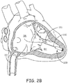
- Fixation member 115 like in device 100, holds electrode 111 in intimate contact with tissue at an implant site, for example, as illustrated in Figure 2B .
- device 1200 includes a sensing extension 1210 on which sense electrode 1211 is mounted.
- Sensing extension 1210 extends proximally from a proximal end 1251 of device housing 1205, such that sense electrode 1211 is spaced a distance X from proximal end 1251 of housing 1205.
- the distance X locates sense electrode 1211 for atrial sensing (P-waves), when device 1200 is implanted in the right ventricle RV, for example, as shown in Figure 2B .
- the distance X may be between approximately 6 cm and approximately 10 cm, such that electrode 1211 is located in the right ventricle RV, as shown; or, according to alternate embodiments, distance X may be between approximately 10 cm and approximately 15 cm, such that electrode is located in the right atrium RA, for example, as indicated with the dashed line in Figure 2B .
- sensing extension 1210 includes an insulated conductor 1213, for example, a coiled medical grade stainless steel or MP35N wire disposed within a medical grade silicone or polyurethane jacket, which is electrically coupled to device housing 1205, for example, via a crimp or a weld.
- insulated conductor 1213 for example, a coiled medical grade stainless steel or MP35N wire disposed within a medical grade silicone or polyurethane jacket, which is electrically coupled to device housing 1205, for example, via a crimp or a weld.
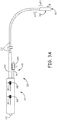
- Figure 3A is a plan view of a delivery tool 200 that may be included together with device 1200 in an interventional medical system, according to some embodiments.
- Figure 3A illustrates tool 200 including a handle 210, and an outer assembly, which is formed by an elongate deployment tube 230 and an outer, stabilizing sheath 270 that surrounds a proximal portion of deployment tube 230 in proximity to handle 210.
- Figure 3B is a longitudinal cross-section view through handle 210, in which a proximal end of sheath 270 is shown secured to handle 210, and a proximal end of deployment tube 230 is shown coupled to a control member 212 of handle 210 such that tube 230 is moveable, via control member 212, relative to sheath 270, according to some embodiments.
- tool 200 also includes an elongate inner member 220, which extends within a lumen of deployment tube 230 and an entirety of deployment tube 230 is also movable with respect to the inner member 220, via control member 212.
- Inner member 220 includes a distal end (not shown), which is located within a distal-most portion 232 of deployment tube 230 and is configured to engage an implantable medical device by abutting an end of the device, for example, proximal end 1251 of device 1200.
- Figures 3A-B further illustrate tool 200 including a flushing subassembly 215 coupled to handle 210, wherein subassembly 215 includes a tube 25 defining a flush lumen, which extends between a connector port 205 (e.g., a stopcock type fitting) and one or more lumens of inner member 220.
- a connector port 205 e.g., a stopcock type fitting
- the arrow in Figure 3B indicates the flow of a flushing fluid (e.g., saline) from the flush lumen to the one or more lumens of inner member 220, and, although not shown, inner member 220 may include one or more ports formed in the sidewall thereof to allow the flushing fluid to flow through the lumen of deployment tube 230 as well.
- a flushing fluid e.g., saline
- the lumen of deployment tube 230 along a length of distal-most portion 232, is sized to contain the distal end of inner member 220 along with the entirety of device housing 1205; and a lumen (not shown) of inner member 220, which extends proximally from an opening terminating the distal end of inner member 220, is sized to accommodate sensing extension 1210 of device 1200, when the distal end of inner member 220 abuts proximal end 1251 of device housing 1205.
- a distal portion of tool 200 may be navigated to a target implant site, for example, in the right ventricle RV by advancing tool 200 through a venous system of the patient, for example, from a femoral venous access site and up through the inferior vena cava IVC ( Figure 2B ).
- a length of deployment tube 230, between handle 210 and distal opening 203 of deployment tube 230, when tube 230 is in the position shown in Figure 3A may be between approximately 103 cm and approximately 107 cm, for example, to reach the right ventricle RV from the femoral access site.
- delivery tool 200 includes articulating features to facilitate the navigation of the distal portion of delivery tool 200 to the target implant site; for example, inner member 220 of delivery tool 200 may include a pull wire (not shown) integrated therein and coupled to another control member 211 of handle 210 that, when moved per arrow A, causes inner member 220 and deployment tube 230 to bend along distal portions thereof.
- a delivery tool like tool 200 is described in co-pending and commonly assigned U.S. Patent Application, Serial No. 14/039,937 .
- control member 212 may be moved, per arrow B, to withdraw deployment tube 230, per arrow W, and expose fixation member 115 ( Figure 2A ) of device 1200 for engagement with tissue at the target site.
- pacing and sensing performance of device 1200 may be evaluated without having to withdraw delivery tool 200 proximally from device 1200 to expose a remainder of device 1200, because, according to embodiments of the present invention, tool 200 includes conductive features for creating a conductive pathway between sense electrode 1211 of device sensing extension 1210 and a location outside tool 200 (e.g., the blood pool of the patient's venous system), while sensing extension 1210 is still contained within inner member 220 and deployment tube 230.
- Figure 3A illustrates potential locations of one or more outer conductive features ocF1, ocF2 of deployment tube 230, which work in conjunction with inner conductive features of inner member 220 to create the conductive pathway, according to various embodiments described below.
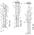
- Figures 4A-C are partial cut-away section views of a distal portion of an interventional medical system that includes a delivery tool 400, which is similar, in some respects, to delivery tool 200, according to some embodiments of the present invention.
- Figures 4A-C illustrate tool 400 including an inner member 420 and a deployment tube 430, wherein inner member 420 extends within a lumen 435 of tube 430, and tube 430 is movable with respect to inner member 420, for example, via a control member of a handle of tool 400, for example, control member 212 of handle 210 ( Figure 3B ).
- Figure 4A shows and entirety of device 1200 contained within the distal portion of tool 400, with device housing 1205, electrode 111, and fixation member 115 all located in a distal-most portion 432 of deployment tube 430, and with housing 1205 abutting a distal end 422 of inner member 420 so that sensing extension 1210 of device 1200 (shown with dashed lines) extends within a lumen of inner member 420.
- distal-most portion 432 has a length of approximately 3.5 cm (-1.4 inch), an inner diameter of approximately 0.275 inch (-0.7 cm), and an outer diameter of approximately 0.3 inch (-0.8 cm).
- Distal end 422 of inner member 420 is shown being enlarged relative to a remainder of inner member 420 and thus constrained from moving proximally out of distal-most portion 432 by a shoulder 431 of distal-most portion 432, according to some embodiments.
- the lumen of inner member 420 extends proximally from an opening thereof that terminates distal end 422 of inner member 420, and, according to an exemplary embodiment, the lumen of inner member 420 has a diameter between approximately 1.8 mm (0.070 inch) and approximately 2.4 mm (0.095 inch), to accommodate sensing extension 1210 extending therein.
- the lumen of inner member 420 extends to a proximal end of inner member 420, for example, which is located within handle 210 of tool 400; according to some alternate embodiments, inner member 420 includes a multi-lumen length extending from the proximal end of inner member 420 to the above-described portion of the lumen that accommodates device sensing extension 1210.
- Figures 4A-C further illustrate deployment tube 430 including outer conductive features 41, 42, and inner member 420 including an inner conductive feature 405, wherein conductive features 41, 42, 405 are defined by apertures formed through a wall of deployment tube 430 and a wall of inner member 420, respectively.
- inner conductive feature 405 is located to provide a conductive pathway, via fluid communication, between sense electrode 1211 of device extension 1210 and one of outer conductive features 41, 42 of deployment tube 430, when aligned therewith, as shown in Figure 4B or Figure 4C .
- outer conductive feature 41 which is located proximal to distal-most portion 432 of tube 430, is approximately aligned with inner conductive feature 405 to allow conduction via fluid communication between the blood pool outside deployment tube 430 and sense electrode 1211.
- a saline flush for example, injected at connector port 205 (described above in conjunction with Figures 3A-B ), through the lumen of inner member 420, and through features 41, 405 can create a conductive pathway, per double-headed arrow f, which allows the operator to evaluate sensing via sense electrode 1211, for example, the sensing of atrial activity (e.g., P-waves) when the implant site is in the right ventricle RV.
- atrial activity e.g., P-waves
- outer conductive feature 42 which is located along distal-most portion 432 of tube 430, is aligned with inner conductive feature 405 to also allow fluid communication that creates the conductive pathway, per arrow f, thereby allowing the aforementioned sensing evaluation.
- blood flow into lumen 435 of deployment tube 430, through one or both of features 41, 42, and then into the lumen of inner member 420, through feature 405, can create a sufficient conductive pathway.
- Each conductive feature 41, 42, 405 may include a single aperture or a plurality of apertures, for example, formed about a perimeter of the respective wall.
- Figures 4A-C illustrate deployment tube 430 including two outer conductive features 41, 42, according to some alternate embodiments, deployment tube 430 includes only one of outer conductive features 41, 42.
- Figures 5A-B are partial cut-away section views of a distal portion of an interventional medical system that includes a delivery tool 500, according to some alternate embodiments and methods.
- Figure 5A illustrates tool 500 including an inner member 520 and a deployment tube 530, wherein inner member 520 extends within a lumen 535 of tube 530, and tube 530 is movable with respect to inner member 520, for example, via a control member of a handle of tool 500, for example, control member 212 of handle 210 ( Figure 3B ).
- Figure 5A shows device 1200 contained in a distal-most portion 532 of tube 530 with device housing 1205 abutting a distal end 522 of inner member 520, and with device sensing extension 1210, again shown with dashed lines, extending within a lumen of inner member 520, wherein the lumen is similar to that of inner member 420 described above.
- Figures 5A-B further illustrate deployment tube 530 including an outer conductive feature 51, and inner member 520 including an inner conductive feature 505, wherein conductive features 51, 505 are defined by electrically conductive segments of a wall of deployment tube 530 and a wall of inner member 520, respectively.
- sensing extension 1210 when sensing extension 1210 extends within the lumen of inner member 520, as shown, electrode 1211 of sensing extension 1210 may interface with inner conductive feature 505 to make electrical contact therewith; and, with reference to Figure 5B , when an operator initially retracts/withdraws deployment tube 530, per arrow W, to expose device fixation member 115 out through a distal opening 503 of lumen 535 of tube 530, and has pushed inner member 520 to engage fixation member 115 with tissue T at an implant site, outer conductive feature 51, for example, located proximal to distal-most portion 532 of tube 530, is aligned with inner conductive feature 505 to make electrical contact therewith.
- outer conductive feature 51 is in conductive contact with the blood pool outside tool 500, so that the aligned conductive features 51, 505, for example, as illustrated in Figure 5B , provide a conductive pathway between the interfacing sense electrode 1211 and the blood pool, which allows the operator to evaluate sensing via sense electrode 1211, for example, the sensing of atrial activity (e.g., P-waves) as described above, without having to withdraw tool 500 from over an entirety of device 1200.
- atrial activity e.g., P-waves
- the interfaces between sense electrode 1211 and inner conductive feature 505, and between inner conductive feature 505 and outer conductive feature 51 may be ones of direct electrical contact, or simply through conductors where direct contact is not required; in either case features 505, 51 provide the conductive pathway between sense electrode 1211 and the blood pool outside tube 530.
- the electrically conductive segments of inner and outer conductive features 505, 51 are formed by a conductive material dispersed within the walls of inner member 520 and deployment tube 530, for example, being in the form of a woven braid of electrically conductive strands, such as fine stainless steel wire, integrated into the walls, wherein, a bulk of each wall may be formed from a polyether block amide.
- the conductive segments of inner and outer conductive features 505, 51 are formed by electrically conductive inserts joined to the walls of inner member 520 and deployment tube 530, for example, stainless steel rings.
- inner conductive feature 405, 505 of each tool 400, 500 is located relative to distal end 422, 522 of the corresponding inner member 420, 520 to either accommodate a length of sensing extension 1210 in which distance X is between approximately 6 cm and approximately 10 cm, such that electrode 1211 is located in the right ventricle RV, or to accommodate a longer length of sensing extension 1210 in which distance X is between approximately 10 cm and approximately 15 cm, such that electrode is located in the right atrium RA.
- the operator may withdraw tool 400, 500 from over an entirety of the implanted device 1200.
- an optional eyelet feature terminating a proximal end of sensing extension 1210 is shown with dashed lines.
- tether 12 shown with dashed lines in Figures 4A and 5A
- tether 12 may extend within the lumen of inner member 420, 520 and out from a proximal opening 13 thereof, so that the operator may have access to the tether in proximity to handle 210.
- a proximal end of tether 12 may be attached to a holder (not shown) that fits within a receptacle 206 of handle 210, and a valve member 286 of handle 210 (e.g., a stop-cock type valve) may be configured to alternately secure and release tether 12 within the lumen of inner member 420, 520.
- a valve member 286 of handle 210 e.g., a stop-cock type valve
- the operator may open valve member 286 to release tether 12, grasp the tether holder, and tug with tether 12 on device 1200 to test the engagement of fixation member 115 or to disengage fixation member 115, if the operator has determined that it is necessary to reposition device 1200 at another implant site.
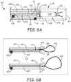
- interventional medical systems of the present invention may employ a snare member, for example, as illustrated in Figures 6A-B.
- Figure 6A is a cross-section view through a distal portion of yet another delivery tool 600; and
- Figure 6B is a schematic demonstrating an opening operation of a snare member of tool 600.
- Figure 6A illustrates tool 600, like tools 400, 500, including an inner member 620 and a deployment tube 630, wherein inner member 620 extends within a lumen 635 of tube 630, and tube 630 is movable with respect to inner member 620, as described above for tools 400, 500, for example, via a control member of a handle of tool 600, for example, control member 212 of handle 210 ( Figures 3A-B ).
- Figure 6A shows device 1200 contained in a distal-most portion 632 of tube 630 with device housing 1205 abutting a distal end 622 of inner member 620, and with device sensing extension 1210, extending within a lumen 625 of inner member 620 such that sense electrode 1211 interfaces with an inner conductive feature 605 of inner member 620.
- Figure 6A further illustrates the snare member of delivery tool 600 including an elongate shaft 642 and a loop 641 coupled to a distal end of shaft 642 at a junction 63.
- Snare member shaft 642 extends alongside sensing extension 1210 within lumen 625 of inner member 620, and loop 641 is closed around a snare attachment feature 1253 of device housing 1205 (feature 1253 also seen in Figure 2A ), when junction 63 of the snare member is located within lumen 625, as shown in Figure 6A , so that a majority of loop 641 is constrained within lumen 625.
- the snare member is slideably engaged within lumen 625, but a proximal segment of shaft 642 may be secured against sliding by valve member 286 of handle 210 ( Figure 3B ) to keep loop 641 closed around feature 1253 of device 1200 while an operator navigates distal-most portion 632 of delivery tool 600, with device 1200 contained therein, to a target implant site (e.g., in the right ventricle RV), and while the operator retracts deployment tube 630 relative to inner member 620 and device 1200 and engages fixation member 115 of device 1200 at the target implant site by pushing on inner member 620.
- a target implant site e.g., in the right ventricle RV
- Figure 6A further illustrates deployment tube 630 of delivery tool 600 including an outer conductive feature 61 located at a proximal end of distal-most portion 632, so that, when deployment tube 630 is retracted to expose device fixation member 115 for engagement with tissue at the target implant site, inner conductive feature 605 of inner member 620 comes into electrical contact with outer conductive feature 61 to provide a conductive pathway between sense electrode 1211, interfacing with inner conductive feature 605, and a location outside deployment tube 630, for example, the blood pool in the right ventricle RV.
- sensing via electrode 1211 may be evaluated, via the conductive pathway, without having to withdraw tool 600 from over an entirety of device 1200.
- inner and outer conductive features 605, 61 are formed by electrically conductive segments, for example, integrated into the walls of inner member 620 and deployment tube 630, respectfully, according to any of the embodiments described above.
- inner and outer conductive features 605, 61 may be defined by apertures formed through a wall of inner member 620 and a wall of deployment tube 630, respectively, to provide conduction via fluid communication between sense electrode 1211 and the blood pool outside deployment tube 630, as described above for delivery tool 400.
- the operator may release device 1200 from the snare member.
- the snare member is released when the operator advances, or pushes shaft 642 of the snare member distally, per arrow p, to open snare loop 641, per arrows o.
- the operator can test fixation of the engaged fixation member 115 by applying a tug force to snare shaft 642; also, the operator can employ the snare member, with snare loop 641 closed around device attachment feature 1253, to disengage fixation member 115, if the operator has determined that it is necessary to reposition device 1200 at another implant site.
Landscapes
- Health & Medical Sciences (AREA)
- Life Sciences & Earth Sciences (AREA)
- Engineering & Computer Science (AREA)
- Biomedical Technology (AREA)
- Animal Behavior & Ethology (AREA)
- General Health & Medical Sciences (AREA)
- Public Health (AREA)
- Veterinary Medicine (AREA)
- Nuclear Medicine, Radiotherapy & Molecular Imaging (AREA)
- Surgery (AREA)
- Heart & Thoracic Surgery (AREA)
- Radiology & Medical Imaging (AREA)
- Pathology (AREA)
- Medical Informatics (AREA)
- Molecular Biology (AREA)
- Cardiology (AREA)
- Biophysics (AREA)
- Pulmonology (AREA)
- Anesthesiology (AREA)
- Hematology (AREA)
- Surgical Instruments (AREA)
- Electrotherapy Devices (AREA)
Claims (8)
- Système médical d'intervention comprenant :un dispositif médical implantable (1200) comprenant un dispositif de commande électronique, une capsule hermétiquement scellée (1205) contenant le dispositif de commande, et une extension de détection (1210) couplée au dispositif de commande, l'extension s'étendant extérieurement à partir d'une extrémité proximale de la capsule, l'extension comportant une électrode de détection (1211) ;un outil de livraison (200) facilitant le déploiement du dispositif, l'outil comprenant :une poignée (210) comportant un élément de commande (212) ;un élément interne allongé (220) comportant une extrémité proximale fixée à la poignée, une extrémité distale, un élément conducteur interne (405) situé à proximité de l'extrémité distale de l'élément interne, et une lumière s'étendant de manière proximale à partir d'une ouverture de celui-ci qui termine l'extrémité distale de l'élément interne, l'extrémité distale de l'élément interne étant configurée pour venir en butée contre l'extrémité proximale de la capsule de dispositif, et la lumière étant dimensionnée pour recevoir l'extension du dispositif, lorsque l'extrémité distale de l'élément interne vient en butée contre l'extrémité proximale du dispositif, de sorte que l'électrode de détection est en interface avec l'élément conducteur interne ; etun tube de déploiement allongé (230) comportant une extrémité proximale couplée à l'élément de commande de la poignée, une partie la plus distale (232), une lumière s'étendant d'une ouverture de celui-ci au niveau de l'extrémité proximale du tube de déploiement à une autre ouverture (203) de celui-ci qui termine la partie la plus distale au niveau d'une extrémité distale de celui-ci, et un élément conducteur externe (41, 42) situé le long ou à proximité de la partie la plus distale, l'élément interne s'étendant à l'intérieur de la lumière du tube de déploiement, un ensemble du tube de déploiement étant mobile longitudinalement par rapport à l'élément interne au moyen de l'élément de commande de la poignée, et la lumière du tube de déploiement, le long d'une longueur de la partie la plus distale, étant dimensionnée pour contenir en même temps l'extrémité distale de l'élément interne avec un ensemble de la capsule du dispositif ;dans lequel l'élément conducteur interne (405) de l'élément interne est configuré pour fournir une voie conductrice entre l'électrode de détection d'interface de l'extension de détection du dispositif et l'élément conducteur externe (42) du tube de déploiement, et l'élément conducteur externe du tube de déploiement est configuré pour fournir une voie conductrice entre l'élément conducteur interne et un emplacement à l'extérieur du tube de déploiement, lorsque les éléments conducteurs interne et externe sont approximativement alignés l'un avec l'autre par l'intermédiaire du mouvement du tube de déploiement par rapport à l'élément interne.
- Système selon la revendication 1, dans lequel chacun des éléments conducteurs interne et externe (41, 42, 405) de l'outil comprend une ou plusieurs ouvertures assurant la conduction par l'intermédiaire d'une communication fluidique entre l'emplacement à l'extérieur du tube de déploiement et l'électrode de détection de l'extension du dispositif, lorsque la lumière de l'élément interne de l'outil reçoit l'extension et que l'extrémité distale de l'élément interne vient en butée contre l'extrémité proximale de la capsule du dispositif, et lorsque les éléments conducteurs interne et externe sont approximativement alignés.
- Système selon l'une quelconque des revendications 1 à 2, dans lequel :l'élément conducteur interne (405) de l'outil comprend un segment électriquement conducteur de l'élément interne de l'outil, le segment conducteur de l'élément interne étant en contact électrique avec l'électrode de détection de l'extension de dispositif, lorsque la lumière de l'élément interne reçoit l'extension et l'extrémité distale de l'élément interne vient en butée contre l'extrémité proximale de la capsule de dispositif ; etl'élément conducteur externe (41, 42) de l'outil comprend un segment électriquement conducteur du tube de déploiement de l'outil, le segment conducteur du tube de déploiement étant en contact électrique avec le segment conducteur de l'élément interne, lorsque les éléments conducteurs interne et externe sont approximativement alignés.
- Système selon l'une quelconque des revendications 1 à 3, dans lequel le segment conducteur de l'élément interne de l'outil comprend un matériau conducteur à l'intérieur d'une paroi de l'élément interne ; et
le segment conducteur du tube de déploiement de l'outil comprend un matériau conducteur à l'intérieur d'une paroi du tube de déploiement. - Système selon l'une quelconque des revendications 1 à 4, dans lequel le segment conducteur de l'élément interne de l'outil comprend un insert conducteur relié à une paroi de l'élément interne ; et
le segment conducteur du tube de déploiement de l'outil comprend un insert conducteur relié à la paroi du tube de déploiement. - Système selon l'une quelconque des revendications 1 à 5, dans lequel :la capsule du dispositif comporte en outre un élément de fixation d'anse situé entre l'extrémité proximale de la capsule de dispositif et l'extension de détection ;l'outil comporte en outre un élément d'anse comportant une tige allongée (642) s'étendant à l'intérieur de la lumière de l'élément interne, et une boucle (641) couplée à une extrémité distale de la tige, l'extrémité distale de la tige étant située à proximité de l'extrémité distale de l'élément interne ; etla boucle de l'élément d'anse est adaptée pour s'ouvrir et se fermer autour de l'élément de fixation d'anse du dispositif par l'intermédiaire du mouvement de la tige de l'élément d'anse à l'intérieur de la lumière de l'élément interne.
- Système selon l'une quelconque des revendications 1 à 6, dans lequel l'électrode de détection de l'extension du dispositif est espacée de l'extrémité proximale de la capsule du dispositif d'une distance comprise entre environ 6 cm et environ 10 cm.
- Système selon l'une quelconque des revendications 1 à 7, dans lequel l'électrode de détection de l'extension du dispositif est espacée de l'extrémité proximale de la capsule du dispositif d'une distance comprise entre environ 10 cm et environ 15 cm.
Applications Claiming Priority (4)
| Application Number | Priority Date | Filing Date | Title |
|---|---|---|---|
| US201462025620P | 2014-07-17 | 2014-07-17 | |
| US201462041927P | 2014-08-26 | 2014-08-26 | |
| US14/518,128 US9446248B2 (en) | 2014-07-17 | 2014-10-20 | Interventional medical systems, tools, and methods of use |
| PCT/US2015/040266 WO2016010958A1 (fr) | 2014-07-17 | 2015-07-14 | Systèmes médicaux d'intervention, outils et procédés d'utilisation |
Publications (2)
| Publication Number | Publication Date |
|---|---|
| EP3193998A1 EP3193998A1 (fr) | 2017-07-26 |
| EP3193998B1 true EP3193998B1 (fr) | 2020-10-21 |
Family
ID=55073703
Family Applications (1)
| Application Number | Title | Priority Date | Filing Date |
|---|---|---|---|
| EP15745644.3A Active EP3193998B1 (fr) | 2014-07-17 | 2015-07-14 | Systèmes médicaux d'intervention |
Country Status (4)
| Country | Link |
|---|---|
| US (1) | US9446248B2 (fr) |
| EP (1) | EP3193998B1 (fr) |
| CN (1) | CN106535794B (fr) |
| WO (1) | WO2016010958A1 (fr) |
Families Citing this family (41)
| Publication number | Priority date | Publication date | Assignee | Title |
|---|---|---|---|---|
| US10071243B2 (en) | 2013-07-31 | 2018-09-11 | Medtronic, Inc. | Fixation for implantable medical devices |
| US10300286B2 (en) | 2013-09-27 | 2019-05-28 | Medtronic, Inc. | Tools and assemblies thereof for implantable medical devices |
| US11110286B2 (en) * | 2014-06-10 | 2021-09-07 | Biotronik Se & Co. Kg | Delivery system for an implantable medical device |
| US9539423B2 (en) | 2014-07-17 | 2017-01-10 | Medtronic, Inc. | Interventional medical systems, tools, and methods of use |
| JP2018504240A (ja) | 2015-02-06 | 2018-02-15 | カーディアック ペースメイカーズ, インコーポレイテッド | 心不整脈を治療するためのシステムおよび方法 |
| US10245072B2 (en) | 2015-07-10 | 2019-04-02 | Medtronic, Inc. | Extravascular medical access tools having boring tip and methods of using such tools |
| US10758729B2 (en) * | 2015-10-01 | 2020-09-01 | Medtronic, Inc. | Interventional medical systems, catheters, and methods |
| US10080888B2 (en) | 2015-11-16 | 2018-09-25 | Medtronic, Inc. | Interventional medical systems and associated methods |
| EP3377174B1 (fr) | 2015-11-20 | 2019-08-28 | Cardiac Pacemakers, Inc. | Systèmes de pose pour dispositifs cardiaques sans sonde |
| AU2016355676B2 (en) | 2015-11-20 | 2018-12-13 | Cardiac Pacemakers, Inc. | Delivery devices and methods for leadless cardiac devices |
| US10099050B2 (en) | 2016-01-21 | 2018-10-16 | Medtronic, Inc. | Interventional medical devices, device systems, and fixation components thereof |
| US10463853B2 (en) | 2016-01-21 | 2019-11-05 | Medtronic, Inc. | Interventional medical systems |
| US10159834B2 (en) | 2016-01-26 | 2018-12-25 | Medtronic, Inc. | Compact implantable medical device and delivery device |
| US10143823B2 (en) * | 2016-04-29 | 2018-12-04 | Medtronic, Inc. | Interventional medical systems and improved assemblies thereof and associated methods of use |
| US10300287B2 (en) * | 2016-06-27 | 2019-05-28 | Medtronic, Inc. | Delivery systems for implantable medical devices, and associated tethering assemblies and methods |
| US10905465B2 (en) | 2016-11-21 | 2021-02-02 | Cardiac Pacemakers, Inc. | Delivery devices and wall apposition sensing |
| US11198013B2 (en) | 2016-11-21 | 2021-12-14 | Cardiac Pacemakers, Inc. | Catheter and leadless cardiac devices including electrical pathway barrier |
| US10485981B2 (en) | 2016-12-27 | 2019-11-26 | Cardiac Pacemakers, Inc. | Fixation methods for leadless cardiac devices |
| EP3562547B1 (fr) * | 2016-12-27 | 2020-11-18 | Cardiac Pacemakers, Inc. | Cathéter d'administration sans fil avec chemin conducteur |
| CN110114114B (zh) | 2016-12-27 | 2023-05-02 | 心脏起搏器股份公司 | 用于无引线心脏装置的递送装置和方法 |
| US10806931B2 (en) | 2016-12-27 | 2020-10-20 | Cardiac Pacemakers, Inc. | Delivery devices and methods for leadless cardiac devices |
| CN110225779B (zh) | 2017-01-26 | 2023-04-04 | 心脏起搏器股份公司 | 用于无引线心脏装置的递送装置 |
| US11229798B2 (en) | 2017-03-10 | 2022-01-25 | Cardiac Pacemakers, Inc. | Fixation for leadless cardiac devices |
| US10994148B2 (en) | 2017-03-20 | 2021-05-04 | Cardiac Pacemakers, Inc. | Systems and methods for treating cardiac arrhythmias |
| CN110461411B (zh) | 2017-03-20 | 2023-06-09 | 心脏起搏器股份公司 | 用于治疗心律失常的无引线起搏装置 |
| EP3600535B1 (fr) | 2017-03-20 | 2021-11-17 | Cardiac Pacemakers, Inc. | Dispositif de stimulation sans fil de traitement d'arythmies cardiaques |
| US11160989B2 (en) | 2017-03-20 | 2021-11-02 | Cardiac Pacemakers, Inc. | Systems and methods for treating cardiac arrhythmias |
| US10737092B2 (en) | 2017-03-30 | 2020-08-11 | Cardiac Pacemakers, Inc. | Delivery devices and methods for leadless cardiac devices |
| CA3068088C (fr) | 2017-06-23 | 2024-01-23 | Medcan Pharma A/S | Sachet de cannabinoides |
| US11577085B2 (en) | 2017-08-03 | 2023-02-14 | Cardiac Pacemakers, Inc. | Delivery devices and methods for leadless cardiac devices |
| EP3727578B1 (fr) | 2017-12-22 | 2022-02-16 | Cardiac Pacemakers, Inc. | Dispositif médical implantable pour déploiement vasculaire |
| WO2019126281A1 (fr) | 2017-12-22 | 2019-06-27 | Cardiac Pacemakers, Inc. | Dispositif médical implantable pour déploiement vasculaire |
| US11759632B2 (en) | 2019-03-28 | 2023-09-19 | Medtronic, Inc. | Fixation components for implantable medical devices |
| WO2020205401A1 (fr) | 2019-03-29 | 2020-10-08 | Cardiac Pacemakers, Inc. | Systèmes et procédés de traitement d'arythmies cardiaques |
| EP3946556B1 (fr) | 2019-03-29 | 2024-06-19 | Cardiac Pacemakers, Inc. | Systèmes de traitement d'arythmies cardiaques |
| US11382663B2 (en) | 2019-05-03 | 2022-07-12 | Pacesetter, Inc. | Biostimulator retrieval system having cincher tube |
| US11938279B2 (en) * | 2019-08-15 | 2024-03-26 | Medtronic, Inc. | Valve clamp for device delivery catheter handle |
| WO2021050685A1 (fr) | 2019-09-11 | 2021-03-18 | Cardiac Pacemakers, Inc. | Outils et systèmes d'implantation et/ou de récupération d'un dispositif de stimulation cardiaque sans fil à fixation hélicoïdale |
| WO2021050679A1 (fr) | 2019-09-11 | 2021-03-18 | Cardiac Pacemakers, Inc. | Outils et systèmes d'implantation et/ou de récupération d'un dispositif de stimulation cardiaque sans fil à fixation hélicoïdale |
| CN112245802B (zh) * | 2020-10-16 | 2023-01-24 | 北京品驰医疗设备有限公司 | 一种导丝柄和植入式医疗系统 |
| US20240058616A1 (en) * | 2022-08-17 | 2024-02-22 | Pacesetter, Inc. | Biostimulator transport system having drive belt |
Family Cites Families (17)
| Publication number | Priority date | Publication date | Assignee | Title |
|---|---|---|---|---|
| US3835864A (en) | 1970-09-21 | 1974-09-17 | Rasor Ass Inc | Intra-cardiac stimulator |
| US4471777A (en) | 1983-03-30 | 1984-09-18 | Mccorkle Jr Charles E | Endocardial lead extraction apparatus and method |
| US4886065A (en) | 1988-08-08 | 1989-12-12 | California Institute Of Technology | In vivo electrode implanting system |
| US7650186B2 (en) | 2004-10-20 | 2010-01-19 | Boston Scientific Scimed, Inc. | Leadless cardiac stimulation systems |
| US7519424B2 (en) | 2006-01-30 | 2009-04-14 | Medtronic, Inc. | Intravascular medical device |
| WO2010088687A1 (fr) | 2009-02-02 | 2010-08-05 | Nanostim, Inc. | Stimulateur cardiaque sans fil doté d'une capacité de fixation auxiliaire |
| US8989873B2 (en) | 2011-07-20 | 2015-03-24 | Medtronic, Inc. | Intravascular medical device with advancable electrode |
| US8758365B2 (en) | 2011-08-03 | 2014-06-24 | Medtronic, Inc. | Implant system including guiding accessory and methods of use |
| US8504156B2 (en) | 2011-08-26 | 2013-08-06 | Medtronic, Inc. | Holding members for implantable cardiac stimulation devices |
| US8945146B2 (en) * | 2011-10-24 | 2015-02-03 | Medtronic, Inc. | Delivery system assemblies and associated methods for implantable medical devices |
| US8781605B2 (en) | 2011-10-31 | 2014-07-15 | Pacesetter, Inc. | Unitary dual-chamber leadless intra-cardiac medical device and method of implanting same |
| US8634912B2 (en) | 2011-11-04 | 2014-01-21 | Pacesetter, Inc. | Dual-chamber leadless intra-cardiac medical device with intra-cardiac extension |
| US8700181B2 (en) | 2011-11-03 | 2014-04-15 | Pacesetter, Inc. | Single-chamber leadless intra-cardiac medical device with dual-chamber functionality and shaped stabilization intra-cardiac extension |
| US20140107723A1 (en) | 2012-10-16 | 2014-04-17 | Pacesetter, Inc. | Single-chamber leadless intra-cardiac medical device with dual-chamber functionality |
| US8670842B1 (en) | 2012-12-14 | 2014-03-11 | Pacesetter, Inc. | Intra-cardiac implantable medical device |
| US8634919B1 (en) | 2012-12-20 | 2014-01-21 | Pacesetter, Inc. | Intracardiac implantable medical device for biatrial and/or left heart pacing and method of implanting same |
| US9283382B2 (en) * | 2014-04-01 | 2016-03-15 | Medtronic, Inc. | Interventional medical systems, tools, and associated methods |
-
2014
- 2014-10-20 US US14/518,128 patent/US9446248B2/en active Active
-
2015
- 2015-07-14 CN CN201580038864.5A patent/CN106535794B/zh active Active
- 2015-07-14 EP EP15745644.3A patent/EP3193998B1/fr active Active
- 2015-07-14 WO PCT/US2015/040266 patent/WO2016010958A1/fr not_active Ceased
Non-Patent Citations (1)
| Title |
|---|
| None * |
Also Published As
| Publication number | Publication date |
|---|---|
| US20160015983A1 (en) | 2016-01-21 |
| US9446248B2 (en) | 2016-09-20 |
| EP3193998A1 (fr) | 2017-07-26 |
| WO2016010958A1 (fr) | 2016-01-21 |
| CN106535794B (zh) | 2019-02-01 |
| CN106535794A (zh) | 2017-03-22 |
Similar Documents
| Publication | Publication Date | Title |
|---|---|---|
| EP3193998B1 (fr) | Systèmes médicaux d'intervention | |
| EP3194019B1 (fr) | Systèmes médicaux interventionnels, outils et méthodes d'utilisation | |
| US12194292B2 (en) | Interventional medical device and method of use | |
| EP3448490B1 (fr) | Systèmes médicaux d'intervention et ensembles | |
| US9414857B2 (en) | Delivery system assemblies for implantable medical devices | |
| US10130821B2 (en) | Interventional medical systems and associated tethering assemblies and methods | |
| US11207530B2 (en) | Relatively compact implantable medical devices and associated methods for loading the devices into a delivery catheter | |
| US9675798B2 (en) | Interventional medical systems, devices, and components thereof | |
| EP3062875B1 (fr) | Outils et leurs ensembles pour dispositifs médicaux implantables | |
| US6185464B1 (en) | Arrangement for planting an endocardial cardiac lead | |
| US9750931B2 (en) | Interventional medical systems, assemblies and methods | |
| US20090198251A1 (en) | Lead delivery, fixation and extraction devices and methods for use with intravascular implantable medical devices | |
| US20190290324A1 (en) | Explantation accessory for an intracorporeal capsule | |
| WO2024213955A1 (fr) | Élément de retenue de dispositif médical |
Legal Events
| Date | Code | Title | Description |
|---|---|---|---|
| STAA | Information on the status of an ep patent application or granted ep patent |
Free format text: STATUS: THE INTERNATIONAL PUBLICATION HAS BEEN MADE |
|
| PUAI | Public reference made under article 153(3) epc to a published international application that has entered the european phase |
Free format text: ORIGINAL CODE: 0009012 |
|
| STAA | Information on the status of an ep patent application or granted ep patent |
Free format text: STATUS: REQUEST FOR EXAMINATION WAS MADE |
|
| 17P | Request for examination filed |
Effective date: 20170216 |
|
| AK | Designated contracting states |
Kind code of ref document: A1 Designated state(s): AL AT BE BG CH CY CZ DE DK EE ES FI FR GB GR HR HU IE IS IT LI LT LU LV MC MK MT NL NO PL PT RO RS SE SI SK SM TR |
|
| AX | Request for extension of the european patent |
Extension state: BA ME |
|
| DAV | Request for validation of the european patent (deleted) | ||
| DAX | Request for extension of the european patent (deleted) | ||
| RIN1 | Information on inventor provided before grant (corrected) |
Inventor name: HILPISCH, KATHRYN Inventor name: NEAFUS, NOELLE C. Inventor name: BONNER, MATTHEW D. Inventor name: SHELDON, TODD J. Inventor name: WOOD, RONAN |
|
| RIC1 | Information provided on ipc code assigned before grant |
Ipc: A61N 1/372 20060101AFI20200326BHEP Ipc: A61B 17/34 20060101ALI20200326BHEP Ipc: A61N 1/05 20060101ALN20200326BHEP Ipc: A61B 17/00 20060101ALN20200326BHEP Ipc: A61N 1/375 20060101ALN20200326BHEP Ipc: A61B 17/22 20060101ALN20200326BHEP Ipc: A61B 90/00 20160101ALN20200326BHEP |
|
| REG | Reference to a national code |
Ref country code: DE Ref legal event code: R079 Ref document number: 602015060803 Country of ref document: DE Free format text: PREVIOUS MAIN CLASS: A61M0025000000 Ipc: A61N0001372000 |
|
| GRAP | Despatch of communication of intention to grant a patent |
Free format text: ORIGINAL CODE: EPIDOSNIGR1 |
|
| STAA | Information on the status of an ep patent application or granted ep patent |
Free format text: STATUS: GRANT OF PATENT IS INTENDED |
|
| RIC1 | Information provided on ipc code assigned before grant |
Ipc: A61B 90/00 20160101ALN20200430BHEP Ipc: A61N 1/375 20060101ALN20200430BHEP Ipc: A61B 17/22 20060101ALN20200430BHEP Ipc: A61N 1/05 20060101ALN20200430BHEP Ipc: A61B 17/34 20060101ALI20200430BHEP Ipc: A61N 1/372 20060101AFI20200430BHEP Ipc: A61B 17/00 20060101ALN20200430BHEP |
|
| INTG | Intention to grant announced |
Effective date: 20200513 |
|
| GRAS | Grant fee paid |
Free format text: ORIGINAL CODE: EPIDOSNIGR3 |
|
| GRAA | (expected) grant |
Free format text: ORIGINAL CODE: 0009210 |
|
| STAA | Information on the status of an ep patent application or granted ep patent |
Free format text: STATUS: THE PATENT HAS BEEN GRANTED |
|
| AK | Designated contracting states |
Kind code of ref document: B1 Designated state(s): AL AT BE BG CH CY CZ DE DK EE ES FI FR GB GR HR HU IE IS IT LI LT LU LV MC MK MT NL NO PL PT RO RS SE SI SK SM TR |
|
| REG | Reference to a national code |
Ref country code: GB Ref legal event code: FG4D |
|
| REG | Reference to a national code |
Ref country code: CH Ref legal event code: EP |
|
| REG | Reference to a national code |
Ref country code: DE Ref legal event code: R096 Ref document number: 602015060803 Country of ref document: DE |
|
| REG | Reference to a national code |
Ref country code: IE Ref legal event code: FG4D |
|
| REG | Reference to a national code |
Ref country code: AT Ref legal event code: REF Ref document number: 1325233 Country of ref document: AT Kind code of ref document: T Effective date: 20201115 |
|
| REG | Reference to a national code |
Ref country code: AT Ref legal event code: MK05 Ref document number: 1325233 Country of ref document: AT Kind code of ref document: T Effective date: 20201021 |
|
| REG | Reference to a national code |
Ref country code: NL Ref legal event code: MP Effective date: 20201021 |
|
| PG25 | Lapsed in a contracting state [announced via postgrant information from national office to epo] |
Ref country code: NL Free format text: LAPSE BECAUSE OF FAILURE TO SUBMIT A TRANSLATION OF THE DESCRIPTION OR TO PAY THE FEE WITHIN THE PRESCRIBED TIME-LIMIT Effective date: 20201021 Ref country code: NO Free format text: LAPSE BECAUSE OF FAILURE TO SUBMIT A TRANSLATION OF THE DESCRIPTION OR TO PAY THE FEE WITHIN THE PRESCRIBED TIME-LIMIT Effective date: 20210121 Ref country code: RS Free format text: LAPSE BECAUSE OF FAILURE TO SUBMIT A TRANSLATION OF THE DESCRIPTION OR TO PAY THE FEE WITHIN THE PRESCRIBED TIME-LIMIT Effective date: 20201021 Ref country code: PT Free format text: LAPSE BECAUSE OF FAILURE TO SUBMIT A TRANSLATION OF THE DESCRIPTION OR TO PAY THE FEE WITHIN THE PRESCRIBED TIME-LIMIT Effective date: 20210222 Ref country code: FI Free format text: LAPSE BECAUSE OF FAILURE TO SUBMIT A TRANSLATION OF THE DESCRIPTION OR TO PAY THE FEE WITHIN THE PRESCRIBED TIME-LIMIT Effective date: 20201021 Ref country code: GR Free format text: LAPSE BECAUSE OF FAILURE TO SUBMIT A TRANSLATION OF THE DESCRIPTION OR TO PAY THE FEE WITHIN THE PRESCRIBED TIME-LIMIT Effective date: 20210122 |
|
| REG | Reference to a national code |
Ref country code: LT Ref legal event code: MG4D |
|
| PG25 | Lapsed in a contracting state [announced via postgrant information from national office to epo] |
Ref country code: AT Free format text: LAPSE BECAUSE OF FAILURE TO SUBMIT A TRANSLATION OF THE DESCRIPTION OR TO PAY THE FEE WITHIN THE PRESCRIBED TIME-LIMIT Effective date: 20201021 Ref country code: ES Free format text: LAPSE BECAUSE OF FAILURE TO SUBMIT A TRANSLATION OF THE DESCRIPTION OR TO PAY THE FEE WITHIN THE PRESCRIBED TIME-LIMIT Effective date: 20201021 Ref country code: BG Free format text: LAPSE BECAUSE OF FAILURE TO SUBMIT A TRANSLATION OF THE DESCRIPTION OR TO PAY THE FEE WITHIN THE PRESCRIBED TIME-LIMIT Effective date: 20210121 Ref country code: PL Free format text: LAPSE BECAUSE OF FAILURE TO SUBMIT A TRANSLATION OF THE DESCRIPTION OR TO PAY THE FEE WITHIN THE PRESCRIBED TIME-LIMIT Effective date: 20201021 Ref country code: SE Free format text: LAPSE BECAUSE OF FAILURE TO SUBMIT A TRANSLATION OF THE DESCRIPTION OR TO PAY THE FEE WITHIN THE PRESCRIBED TIME-LIMIT Effective date: 20201021 Ref country code: LV Free format text: LAPSE BECAUSE OF FAILURE TO SUBMIT A TRANSLATION OF THE DESCRIPTION OR TO PAY THE FEE WITHIN THE PRESCRIBED TIME-LIMIT Effective date: 20201021 Ref country code: IS Free format text: LAPSE BECAUSE OF FAILURE TO SUBMIT A TRANSLATION OF THE DESCRIPTION OR TO PAY THE FEE WITHIN THE PRESCRIBED TIME-LIMIT Effective date: 20210221 |
|
| PG25 | Lapsed in a contracting state [announced via postgrant information from national office to epo] |
Ref country code: HR Free format text: LAPSE BECAUSE OF FAILURE TO SUBMIT A TRANSLATION OF THE DESCRIPTION OR TO PAY THE FEE WITHIN THE PRESCRIBED TIME-LIMIT Effective date: 20201021 |
|
| REG | Reference to a national code |
Ref country code: DE Ref legal event code: R097 Ref document number: 602015060803 Country of ref document: DE |
|
| PG25 | Lapsed in a contracting state [announced via postgrant information from national office to epo] |
Ref country code: SK Free format text: LAPSE BECAUSE OF FAILURE TO SUBMIT A TRANSLATION OF THE DESCRIPTION OR TO PAY THE FEE WITHIN THE PRESCRIBED TIME-LIMIT Effective date: 20201021 Ref country code: RO Free format text: LAPSE BECAUSE OF FAILURE TO SUBMIT A TRANSLATION OF THE DESCRIPTION OR TO PAY THE FEE WITHIN THE PRESCRIBED TIME-LIMIT Effective date: 20201021 Ref country code: LT Free format text: LAPSE BECAUSE OF FAILURE TO SUBMIT A TRANSLATION OF THE DESCRIPTION OR TO PAY THE FEE WITHIN THE PRESCRIBED TIME-LIMIT Effective date: 20201021 Ref country code: EE Free format text: LAPSE BECAUSE OF FAILURE TO SUBMIT A TRANSLATION OF THE DESCRIPTION OR TO PAY THE FEE WITHIN THE PRESCRIBED TIME-LIMIT Effective date: 20201021 Ref country code: CZ Free format text: LAPSE BECAUSE OF FAILURE TO SUBMIT A TRANSLATION OF THE DESCRIPTION OR TO PAY THE FEE WITHIN THE PRESCRIBED TIME-LIMIT Effective date: 20201021 Ref country code: SM Free format text: LAPSE BECAUSE OF FAILURE TO SUBMIT A TRANSLATION OF THE DESCRIPTION OR TO PAY THE FEE WITHIN THE PRESCRIBED TIME-LIMIT Effective date: 20201021 |
|
| PLBE | No opposition filed within time limit |
Free format text: ORIGINAL CODE: 0009261 |
|
| STAA | Information on the status of an ep patent application or granted ep patent |
Free format text: STATUS: NO OPPOSITION FILED WITHIN TIME LIMIT |
|
| PG25 | Lapsed in a contracting state [announced via postgrant information from national office to epo] |
Ref country code: DK Free format text: LAPSE BECAUSE OF FAILURE TO SUBMIT A TRANSLATION OF THE DESCRIPTION OR TO PAY THE FEE WITHIN THE PRESCRIBED TIME-LIMIT Effective date: 20201021 |
|
| 26N | No opposition filed |
Effective date: 20210722 |
|
| PG25 | Lapsed in a contracting state [announced via postgrant information from national office to epo] |
Ref country code: AL Free format text: LAPSE BECAUSE OF FAILURE TO SUBMIT A TRANSLATION OF THE DESCRIPTION OR TO PAY THE FEE WITHIN THE PRESCRIBED TIME-LIMIT Effective date: 20201021 Ref country code: IT Free format text: LAPSE BECAUSE OF FAILURE TO SUBMIT A TRANSLATION OF THE DESCRIPTION OR TO PAY THE FEE WITHIN THE PRESCRIBED TIME-LIMIT Effective date: 20201021 |
|
| PG25 | Lapsed in a contracting state [announced via postgrant information from national office to epo] |
Ref country code: SI Free format text: LAPSE BECAUSE OF FAILURE TO SUBMIT A TRANSLATION OF THE DESCRIPTION OR TO PAY THE FEE WITHIN THE PRESCRIBED TIME-LIMIT Effective date: 20201021 |
|
| REG | Reference to a national code |
Ref country code: CH Ref legal event code: PL |
|
| GBPC | Gb: european patent ceased through non-payment of renewal fee |
Effective date: 20210714 |
|
| PG25 | Lapsed in a contracting state [announced via postgrant information from national office to epo] |
Ref country code: MC Free format text: LAPSE BECAUSE OF FAILURE TO SUBMIT A TRANSLATION OF THE DESCRIPTION OR TO PAY THE FEE WITHIN THE PRESCRIBED TIME-LIMIT Effective date: 20201021 |
|
| REG | Reference to a national code |
Ref country code: BE Ref legal event code: MM Effective date: 20210731 |
|
| PG25 | Lapsed in a contracting state [announced via postgrant information from national office to epo] |
Ref country code: LI Free format text: LAPSE BECAUSE OF NON-PAYMENT OF DUE FEES Effective date: 20210731 Ref country code: GB Free format text: LAPSE BECAUSE OF NON-PAYMENT OF DUE FEES Effective date: 20210714 Ref country code: CH Free format text: LAPSE BECAUSE OF NON-PAYMENT OF DUE FEES Effective date: 20210731 |
|
| PG25 | Lapsed in a contracting state [announced via postgrant information from national office to epo] |
Ref country code: IS Free format text: LAPSE BECAUSE OF FAILURE TO SUBMIT A TRANSLATION OF THE DESCRIPTION OR TO PAY THE FEE WITHIN THE PRESCRIBED TIME-LIMIT Effective date: 20210221 Ref country code: LU Free format text: LAPSE BECAUSE OF NON-PAYMENT OF DUE FEES Effective date: 20210714 |
|
| PG25 | Lapsed in a contracting state [announced via postgrant information from national office to epo] |
Ref country code: IE Free format text: LAPSE BECAUSE OF NON-PAYMENT OF DUE FEES Effective date: 20210714 Ref country code: BE Free format text: LAPSE BECAUSE OF NON-PAYMENT OF DUE FEES Effective date: 20210731 |
|
| PG25 | Lapsed in a contracting state [announced via postgrant information from national office to epo] |
Ref country code: HU Free format text: LAPSE BECAUSE OF FAILURE TO SUBMIT A TRANSLATION OF THE DESCRIPTION OR TO PAY THE FEE WITHIN THE PRESCRIBED TIME-LIMIT; INVALID AB INITIO Effective date: 20150714 |
|
| PG25 | Lapsed in a contracting state [announced via postgrant information from national office to epo] |
Ref country code: CY Free format text: LAPSE BECAUSE OF FAILURE TO SUBMIT A TRANSLATION OF THE DESCRIPTION OR TO PAY THE FEE WITHIN THE PRESCRIBED TIME-LIMIT Effective date: 20201021 |
|
| PG25 | Lapsed in a contracting state [announced via postgrant information from national office to epo] |
Ref country code: MK Free format text: LAPSE BECAUSE OF FAILURE TO SUBMIT A TRANSLATION OF THE DESCRIPTION OR TO PAY THE FEE WITHIN THE PRESCRIBED TIME-LIMIT Effective date: 20201021 |
|
| PG25 | Lapsed in a contracting state [announced via postgrant information from national office to epo] |
Ref country code: MT Free format text: LAPSE BECAUSE OF FAILURE TO SUBMIT A TRANSLATION OF THE DESCRIPTION OR TO PAY THE FEE WITHIN THE PRESCRIBED TIME-LIMIT Effective date: 20201021 |
|
| PGFP | Annual fee paid to national office [announced via postgrant information from national office to epo] |
Ref country code: FR Payment date: 20250620 Year of fee payment: 11 |
|
| PGFP | Annual fee paid to national office [announced via postgrant information from national office to epo] |
Ref country code: DE Payment date: 20250620 Year of fee payment: 11 |
|
| PG25 | Lapsed in a contracting state [announced via postgrant information from national office to epo] |
Ref country code: TR Free format text: LAPSE BECAUSE OF FAILURE TO SUBMIT A TRANSLATION OF THE DESCRIPTION OR TO PAY THE FEE WITHIN THE PRESCRIBED TIME-LIMIT Effective date: 20201021 |