EP3194196B1 - Hydrauliksystem - Google Patents
Hydrauliksystem Download PDFInfo
- Publication number
- EP3194196B1 EP3194196B1 EP15766501.9A EP15766501A EP3194196B1 EP 3194196 B1 EP3194196 B1 EP 3194196B1 EP 15766501 A EP15766501 A EP 15766501A EP 3194196 B1 EP3194196 B1 EP 3194196B1
- Authority
- EP
- European Patent Office
- Prior art keywords
- hydraulic system
- electrical motor
- shifting
- piston
- shifting mechanism
- Prior art date
- Legal status (The legal status is an assumption and is not a legal conclusion. Google has not performed a legal analysis and makes no representation as to the accuracy of the status listed.)
- Active
Links
Images



Classifications
-
- B—PERFORMING OPERATIONS; TRANSPORTING
- B60—VEHICLES IN GENERAL
- B60K—ARRANGEMENT OR MOUNTING OF PROPULSION UNITS OR OF TRANSMISSIONS IN VEHICLES; ARRANGEMENT OR MOUNTING OF PLURAL DIVERSE PRIME-MOVERS IN VEHICLES; AUXILIARY DRIVES FOR VEHICLES; INSTRUMENTATION OR DASHBOARDS FOR VEHICLES; ARRANGEMENTS IN CONNECTION WITH COOLING, AIR INTAKE, GAS EXHAUST OR FUEL SUPPLY OF PROPULSION UNITS IN VEHICLES
- B60K1/00—Arrangement or mounting of electrical propulsion units
-
- B—PERFORMING OPERATIONS; TRANSPORTING
- B60—VEHICLES IN GENERAL
- B60K—ARRANGEMENT OR MOUNTING OF PROPULSION UNITS OR OF TRANSMISSIONS IN VEHICLES; ARRANGEMENT OR MOUNTING OF PLURAL DIVERSE PRIME-MOVERS IN VEHICLES; AUXILIARY DRIVES FOR VEHICLES; INSTRUMENTATION OR DASHBOARDS FOR VEHICLES; ARRANGEMENTS IN CONNECTION WITH COOLING, AIR INTAKE, GAS EXHAUST OR FUEL SUPPLY OF PROPULSION UNITS IN VEHICLES
- B60K11/00—Arrangement in connection with cooling of propulsion units
- B60K11/02—Arrangement in connection with cooling of propulsion units with liquid cooling
-
- B—PERFORMING OPERATIONS; TRANSPORTING
- B60—VEHICLES IN GENERAL
- B60K—ARRANGEMENT OR MOUNTING OF PROPULSION UNITS OR OF TRANSMISSIONS IN VEHICLES; ARRANGEMENT OR MOUNTING OF PLURAL DIVERSE PRIME-MOVERS IN VEHICLES; AUXILIARY DRIVES FOR VEHICLES; INSTRUMENTATION OR DASHBOARDS FOR VEHICLES; ARRANGEMENTS IN CONNECTION WITH COOLING, AIR INTAKE, GAS EXHAUST OR FUEL SUPPLY OF PROPULSION UNITS IN VEHICLES
- B60K17/00—Arrangement or mounting of transmissions in vehicles
- B60K17/04—Arrangement or mounting of transmissions in vehicles characterised by arrangement, location or kind of gearing
- B60K17/10—Arrangement or mounting of transmissions in vehicles characterised by arrangement, location or kind of gearing of fluid gearing
-
- B—PERFORMING OPERATIONS; TRANSPORTING
- B60—VEHICLES IN GENERAL
- B60K—ARRANGEMENT OR MOUNTING OF PROPULSION UNITS OR OF TRANSMISSIONS IN VEHICLES; ARRANGEMENT OR MOUNTING OF PLURAL DIVERSE PRIME-MOVERS IN VEHICLES; AUXILIARY DRIVES FOR VEHICLES; INSTRUMENTATION OR DASHBOARDS FOR VEHICLES; ARRANGEMENTS IN CONNECTION WITH COOLING, AIR INTAKE, GAS EXHAUST OR FUEL SUPPLY OF PROPULSION UNITS IN VEHICLES
- B60K23/00—Arrangement or mounting of control devices for vehicle transmissions, or parts thereof, not otherwise provided for
- B60K23/04—Arrangement or mounting of control devices for vehicle transmissions, or parts thereof, not otherwise provided for for differential gearing
-
- F—MECHANICAL ENGINEERING; LIGHTING; HEATING; WEAPONS; BLASTING
- F16—ENGINEERING ELEMENTS AND UNITS; GENERAL MEASURES FOR PRODUCING AND MAINTAINING EFFECTIVE FUNCTIONING OF MACHINES OR INSTALLATIONS; THERMAL INSULATION IN GENERAL
- F16D—COUPLINGS FOR TRANSMITTING ROTATION; CLUTCHES; BRAKES
- F16D25/00—Fluid-actuated clutches
- F16D25/08—Fluid-actuated clutches with fluid-actuated member not rotating with a clutching member
-
- F—MECHANICAL ENGINEERING; LIGHTING; HEATING; WEAPONS; BLASTING
- F16—ENGINEERING ELEMENTS AND UNITS; GENERAL MEASURES FOR PRODUCING AND MAINTAINING EFFECTIVE FUNCTIONING OF MACHINES OR INSTALLATIONS; THERMAL INSULATION IN GENERAL
- F16H—GEARING
- F16H61/00—Control functions within control units of change-speed- or reversing-gearings for conveying rotary motion ; Control of exclusively fluid gearing, friction gearing, gearings with endless flexible members or other particular types of gearing
- F16H61/0021—Generation or control of line pressure
- F16H61/0025—Supply of control fluid; Pumps therefor
-
- F—MECHANICAL ENGINEERING; LIGHTING; HEATING; WEAPONS; BLASTING
- F16—ENGINEERING ELEMENTS AND UNITS; GENERAL MEASURES FOR PRODUCING AND MAINTAINING EFFECTIVE FUNCTIONING OF MACHINES OR INSTALLATIONS; THERMAL INSULATION IN GENERAL
- F16H—GEARING
- F16H61/00—Control functions within control units of change-speed- or reversing-gearings for conveying rotary motion ; Control of exclusively fluid gearing, friction gearing, gearings with endless flexible members or other particular types of gearing
- F16H61/0021—Generation or control of line pressure
- F16H61/0025—Supply of control fluid; Pumps therefor
- F16H61/0031—Supply of control fluid; Pumps therefor using auxiliary pumps, e.g. pump driven by a different power source than the engine
-
- F—MECHANICAL ENGINEERING; LIGHTING; HEATING; WEAPONS; BLASTING
- F16—ENGINEERING ELEMENTS AND UNITS; GENERAL MEASURES FOR PRODUCING AND MAINTAINING EFFECTIVE FUNCTIONING OF MACHINES OR INSTALLATIONS; THERMAL INSULATION IN GENERAL
- F16H—GEARING
- F16H61/00—Control functions within control units of change-speed- or reversing-gearings for conveying rotary motion ; Control of exclusively fluid gearing, friction gearing, gearings with endless flexible members or other particular types of gearing
- F16H61/26—Generation or transmission of movements for final actuating mechanisms
- F16H61/28—Generation or transmission of movements for final actuating mechanisms with at least one movement of the final actuating mechanism being caused by a non-mechanical force, e.g. power-assisted
- F16H61/30—Hydraulic or pneumatic motors or related fluid control means therefor
-
- B—PERFORMING OPERATIONS; TRANSPORTING
- B60—VEHICLES IN GENERAL
- B60K—ARRANGEMENT OR MOUNTING OF PROPULSION UNITS OR OF TRANSMISSIONS IN VEHICLES; ARRANGEMENT OR MOUNTING OF PLURAL DIVERSE PRIME-MOVERS IN VEHICLES; AUXILIARY DRIVES FOR VEHICLES; INSTRUMENTATION OR DASHBOARDS FOR VEHICLES; ARRANGEMENTS IN CONNECTION WITH COOLING, AIR INTAKE, GAS EXHAUST OR FUEL SUPPLY OF PROPULSION UNITS IN VEHICLES
- B60K1/00—Arrangement or mounting of electrical propulsion units
- B60K2001/003—Arrangement or mounting of electrical propulsion units with means for cooling the electrical propulsion units
-
- B—PERFORMING OPERATIONS; TRANSPORTING
- B60—VEHICLES IN GENERAL
- B60K—ARRANGEMENT OR MOUNTING OF PROPULSION UNITS OR OF TRANSMISSIONS IN VEHICLES; ARRANGEMENT OR MOUNTING OF PLURAL DIVERSE PRIME-MOVERS IN VEHICLES; AUXILIARY DRIVES FOR VEHICLES; INSTRUMENTATION OR DASHBOARDS FOR VEHICLES; ARRANGEMENTS IN CONNECTION WITH COOLING, AIR INTAKE, GAS EXHAUST OR FUEL SUPPLY OF PROPULSION UNITS IN VEHICLES
- B60K1/00—Arrangement or mounting of electrical propulsion units
- B60K2001/003—Arrangement or mounting of electrical propulsion units with means for cooling the electrical propulsion units
- B60K2001/006—Arrangement or mounting of electrical propulsion units with means for cooling the electrical propulsion units the electric motors
-
- B—PERFORMING OPERATIONS; TRANSPORTING
- B60—VEHICLES IN GENERAL
- B60K—ARRANGEMENT OR MOUNTING OF PROPULSION UNITS OR OF TRANSMISSIONS IN VEHICLES; ARRANGEMENT OR MOUNTING OF PLURAL DIVERSE PRIME-MOVERS IN VEHICLES; AUXILIARY DRIVES FOR VEHICLES; INSTRUMENTATION OR DASHBOARDS FOR VEHICLES; ARRANGEMENTS IN CONNECTION WITH COOLING, AIR INTAKE, GAS EXHAUST OR FUEL SUPPLY OF PROPULSION UNITS IN VEHICLES
- B60K23/00—Arrangement or mounting of control devices for vehicle transmissions, or parts thereof, not otherwise provided for
- B60K23/04—Arrangement or mounting of control devices for vehicle transmissions, or parts thereof, not otherwise provided for for differential gearing
- B60K2023/043—Control means for varying left-right torque distribution, e.g. torque vectoring
-
- B—PERFORMING OPERATIONS; TRANSPORTING
- B60—VEHICLES IN GENERAL
- B60K—ARRANGEMENT OR MOUNTING OF PROPULSION UNITS OR OF TRANSMISSIONS IN VEHICLES; ARRANGEMENT OR MOUNTING OF PLURAL DIVERSE PRIME-MOVERS IN VEHICLES; AUXILIARY DRIVES FOR VEHICLES; INSTRUMENTATION OR DASHBOARDS FOR VEHICLES; ARRANGEMENTS IN CONNECTION WITH COOLING, AIR INTAKE, GAS EXHAUST OR FUEL SUPPLY OF PROPULSION UNITS IN VEHICLES
- B60K6/00—Arrangement or mounting of plural diverse prime-movers for mutual or common propulsion, e.g. hybrid propulsion systems comprising electric motors and internal combustion engines
- B60K6/20—Arrangement or mounting of plural diverse prime-movers for mutual or common propulsion, e.g. hybrid propulsion systems comprising electric motors and internal combustion engines the prime-movers consisting of electric motors and internal combustion engines, e.g. HEVs
- B60K6/22—Arrangement or mounting of plural diverse prime-movers for mutual or common propulsion, e.g. hybrid propulsion systems comprising electric motors and internal combustion engines the prime-movers consisting of electric motors and internal combustion engines, e.g. HEVs characterised by apparatus, components or means specially adapted for HEVs
- B60K6/26—Arrangement or mounting of plural diverse prime-movers for mutual or common propulsion, e.g. hybrid propulsion systems comprising electric motors and internal combustion engines the prime-movers consisting of electric motors and internal combustion engines, e.g. HEVs characterised by apparatus, components or means specially adapted for HEVs characterised by the motors or the generators
-
- B—PERFORMING OPERATIONS; TRANSPORTING
- B60—VEHICLES IN GENERAL
- B60K—ARRANGEMENT OR MOUNTING OF PROPULSION UNITS OR OF TRANSMISSIONS IN VEHICLES; ARRANGEMENT OR MOUNTING OF PLURAL DIVERSE PRIME-MOVERS IN VEHICLES; AUXILIARY DRIVES FOR VEHICLES; INSTRUMENTATION OR DASHBOARDS FOR VEHICLES; ARRANGEMENTS IN CONNECTION WITH COOLING, AIR INTAKE, GAS EXHAUST OR FUEL SUPPLY OF PROPULSION UNITS IN VEHICLES
- B60K6/00—Arrangement or mounting of plural diverse prime-movers for mutual or common propulsion, e.g. hybrid propulsion systems comprising electric motors and internal combustion engines
- B60K6/20—Arrangement or mounting of plural diverse prime-movers for mutual or common propulsion, e.g. hybrid propulsion systems comprising electric motors and internal combustion engines the prime-movers consisting of electric motors and internal combustion engines, e.g. HEVs
- B60K6/42—Arrangement or mounting of plural diverse prime-movers for mutual or common propulsion, e.g. hybrid propulsion systems comprising electric motors and internal combustion engines the prime-movers consisting of electric motors and internal combustion engines, e.g. HEVs characterised by the architecture of the hybrid electric vehicle
- B60K6/48—Parallel type
-
- B—PERFORMING OPERATIONS; TRANSPORTING
- B60—VEHICLES IN GENERAL
- B60K—ARRANGEMENT OR MOUNTING OF PROPULSION UNITS OR OF TRANSMISSIONS IN VEHICLES; ARRANGEMENT OR MOUNTING OF PLURAL DIVERSE PRIME-MOVERS IN VEHICLES; AUXILIARY DRIVES FOR VEHICLES; INSTRUMENTATION OR DASHBOARDS FOR VEHICLES; ARRANGEMENTS IN CONNECTION WITH COOLING, AIR INTAKE, GAS EXHAUST OR FUEL SUPPLY OF PROPULSION UNITS IN VEHICLES
- B60K6/00—Arrangement or mounting of plural diverse prime-movers for mutual or common propulsion, e.g. hybrid propulsion systems comprising electric motors and internal combustion engines
- B60K6/20—Arrangement or mounting of plural diverse prime-movers for mutual or common propulsion, e.g. hybrid propulsion systems comprising electric motors and internal combustion engines the prime-movers consisting of electric motors and internal combustion engines, e.g. HEVs
- B60K6/50—Architecture of the driveline characterised by arrangement or kind of transmission units
- B60K6/52—Driving a plurality of drive axles, e.g. four-wheel drive
-
- B—PERFORMING OPERATIONS; TRANSPORTING
- B60—VEHICLES IN GENERAL
- B60Y—INDEXING SCHEME RELATING TO ASPECTS CROSS-CUTTING VEHICLE TECHNOLOGY
- B60Y2200/00—Type of vehicle
- B60Y2200/90—Vehicles comprising electric prime movers
- B60Y2200/92—Hybrid vehicles
-
- F—MECHANICAL ENGINEERING; LIGHTING; HEATING; WEAPONS; BLASTING
- F16—ENGINEERING ELEMENTS AND UNITS; GENERAL MEASURES FOR PRODUCING AND MAINTAINING EFFECTIVE FUNCTIONING OF MACHINES OR INSTALLATIONS; THERMAL INSULATION IN GENERAL
- F16H—GEARING
- F16H61/00—Control functions within control units of change-speed- or reversing-gearings for conveying rotary motion ; Control of exclusively fluid gearing, friction gearing, gearings with endless flexible members or other particular types of gearing
- F16H61/0021—Generation or control of line pressure
- F16H2061/0037—Generation or control of line pressure characterised by controlled fluid supply to lubrication circuits of the gearing
-
- Y—GENERAL TAGGING OF NEW TECHNOLOGICAL DEVELOPMENTS; GENERAL TAGGING OF CROSS-SECTIONAL TECHNOLOGIES SPANNING OVER SEVERAL SECTIONS OF THE IPC; TECHNICAL SUBJECTS COVERED BY FORMER USPC CROSS-REFERENCE ART COLLECTIONS [XRACs] AND DIGESTS
- Y02—TECHNOLOGIES OR APPLICATIONS FOR MITIGATION OR ADAPTATION AGAINST CLIMATE CHANGE
- Y02T—CLIMATE CHANGE MITIGATION TECHNOLOGIES RELATED TO TRANSPORTATION
- Y02T10/00—Road transport of goods or passengers
- Y02T10/60—Other road transportation technologies with climate change mitigation effect
- Y02T10/62—Hybrid vehicles
Definitions
- the present invention related to a hydraulic system for a vehicle. More particularly, the present invention relates to a hydraulic system for actuating a shifting mechanism of a vehicle driveline.
- such electrical propulsion motors may be arranged as the only driving unit of the vehicle, or in series or in parallel with a combustion engine thus forming a so called hybrid vehicle.
- WO2010101506 One example of a driving configuration including an electrical driving motor, as well as a torque vectoring motor, is described in WO2010101506 by the same applicant.
- the electrical power system of today's passenger cars is normally based on 12V. Due to the relatively low voltage proposed solutions for high electrical power utilities, such as electrically powered propulsion units, require additional power supplies and high power electronics.
- the above-mentioned prior art driving configuration includes a high power electrical motor for propulsion purposes, and a smaller electrical motor for torque vectoring purposes. Should 48V be available, it would be possible to develop a design for hybrid drive using only a single electrical motor, as well as a transmission being configured to be shifted between a first mode in which the electrical motor is used as a secondary drive source for propulsion, and a second mode in which the electrical motor is used for redistributing driving torque (i.e. from the primary drive).
- An electrical motor either used for propulsion, torque vectoring, or both, may be equipped with hydraulically actuated gears in order to provide a wider range of operating parameters of the electrical motor, e.g. with respect to torque output and rotational speed.
- the present invention preferably seeks to mitigate, alleviate or eliminate one or more of the above-identified deficiencies in the art and disadvantages singly or in any combination and solves at least the above-mentioned problems by providing a method and a device according to the appended claims.
- An idea is to solve the above mentioned drawbacks by providing a hydraulic system which serves to actuate gears by means of a shifting mechanism, which shifting mechanism forms part of a valve which when open allows the hydraulic fluid to cool the electrical motor.
- a hydraulic system for a vehicle comprising a shifting mechanism and a pump assembly configured to provide pressurized fluid to said shifting mechanism, and an electrical motor.
- the movement of the shifting mechanism controls a valve function which serves to open a connection from the pump assembly to the electrical motor.
- the shifting mechanism comprises a moveable shifting piston such that the connection from the pump assembly to the electrical motor is opened only when the shifting piston has reached one of its end positions.
- the hydraulic system may further comprise a pilot valve arranged between the shifting mechanism and the electrical motor.
- the pilot valve may be configured to open when the shifting piston has reached one of its end positions.
- the hydraulic system comprises at least one separate valve being responsive to the movement of the shifting piston.
- the at least one separate valve may be integrated in said shifting piston.
- the pump assembly comprises a reversible pump.
- the shifting mechanism comprises a detention device for keeping the shifting mechanism at a desired shift position.
- the detention device may comprise a plurality of distinct shift positions being separated by a ramped surface.
- a vehicle driveline comprises a hydraulic system according to the first aspect.
- a the hydraulic system includes a shifting mechanism and a pump assembly configured to provide pressurized fluid to said shifting mechanism, as well as an electrical motor.
- the hydraulic system is configured such that the movement of the shifting mechanism controls a valve function which serves to open a connection from the pump assembly to the electrical motor, wherein hydraulic fluid may flow to the electrical motor for cooling of the electrical motor.
- the hydraulic system described below may e.g. be implemented in a driveline configuration having torque vectoring functionality, electric drive functionality, or both.
- the driveline configuration may be constructed such that:
- Hybrid drive is normally desired for passenger cars or other four-wheeled vehicles.
- Hybrid drive may either represent the possibility to change driving source from an internal combustion engine to an electrical motor or vice versa, or the possibility to use an electrical motor driving a front or rear axle, in addition to an internal combustion engine driving the other one of the front or rear axle, in order to provide all wheel drive.
- a driveline configuration for which the torque vectoring device is particularly applicable is a four wheeled vehicle, such as a passenger car, having an internal combustion engine driving the front axle, and an electrically driven rear axle.
- the rear axle is driven by means of an electrical motor forming part of a hydraulic system according to any of the embodiments described herein, and the vehicle may be driven by the internal combustion engine only (i.e. front wheel drive), the electrical motor only (i.e. rear wheel drive), or the internal combustion engine in combination with the electrical motor (i.e. all wheel drive).
- the electrical motor may provide torque vectoring when the internal combustion engine is driving the vehicle.
- Another application is a driveline where the electrical motor is used only for torque vectoring.
- the shifting mechanism is provided in order to shift mode; in cases where the electrical motor is configured to only provide torque vectoring the shifting mechanism changes the mode between neutral (i.e. the electrical motor is disconnected from torque vectoring mode) and engaged (i.e. the electrical motor is connected to torque vectoring mode). In cases where the electrical motor is configured to only provide driving torque, i.e. propulsion, the shifting mechanism changes the mode between neutral (i.e. the electrical motor is disconnected from propulsion mode) and engaged (i.e. the electrical motor is connected to propulsion mode). Additional modes may be available in case speed reduction stages are available for the electrical motor, whereby the shifting mechanism may change mode between neutral, high speed mode, and low speed mode.
- the shifting mechanism changes the mode between neutral (i.e. the electrical motor is disconnected from propulsion as well as torque vectoring), torque vectoring mode, and propulsion mode.
- additional modes may be available in case speed reduction stages are available for the electrical motor, whereby the shifting mechanism may change mode between neutral, high speed mode, low speed mode, and torque vectoring mode.
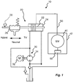
- the hydraulic system 10 comprises a shifting mechanism 20, a pump assembly 30 acting as a pressure source, and an electrical motor 40 configured to provide torque vectoring, propulsion, or both in accordance with the description above.
- the pump assembly 30 is a reversible pump assembly, including an electric motor 32 and a pumping device 34.
- the reversible pump assembly 30 is used to actuate the shifting mechanism 20 in either one of two possible directions.
- the reversible pump assembly 30 is not described in further details herein, but may be implemented in accordance with PCT/SE2015/052024 of the same applicant.
- the shifting mechanism 20 comprises a moveable shifting piston 22 arranged inside a cylinder 24, and a detention device 26 which is moveable with the shifting piston 22.
- the shifting piston 22 and the detention device 26 are moveable between either one of three positions, corresponding to neutral mode, hybrid mode, and torque vectoring (TV) mode.
- a position sensor 28 may be provided to monitor the current position of the shifting piston 22.
- the detention device 26 is used to keep the shifting piston 22 in the selected position (Hybrid/Neutral/TV) also if the pump assembly 30 is shut off.
- the return flow of warm oil can optionally pass a heat exchanger 60 before returning to the tank.
- the heat exchanger 60 can be of oil/air type and be integrated into the electric motor housing 42 as shown in Fig. 1 .
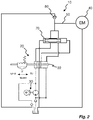
- Fig. 2 shows an alternative embodiment of a hydraulic system 10 where the flow from the shifting piston 22 is used to control a pilot valve 70 for the cooling flow.
- a pilot valve 70 By using a pilot valve 70 the openings for the cooling flow can be made larger and thus the pressure drop can be reduced compared to the system 10 shown in Fig. 1 .
- control fluid for the pilot valve 70 is flown from the pump assembly 30 to the pilot valve 70 via the cylinder 24. Cooling fluid may consequently enter the cooling circuit 50 via the pilot valve 70.
- a floating air valve 80 may be arranged in the fluid circuit for preventing back flow from the pilot valve 70 to the tank.
- Fig. 3 shows a hydraulic system 10 similar to the hydraulic system of Fig. 2 .
- the movement of the shifting piston 22 itself is used to actuate two valves 90a, 90b for controlling the cooling flow to the cooling circuit 50.
- the valve 90b is automatically opened allowing fluid to enter the cooling circuit 50.
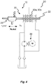
- Fig. 4 shows a hydraulic system 10 where the valves 90a, 90b for controlling the cooling flow to the cooling circuit 50 are integrated in the shifting piston 22.
- valves 90a, 90b are further shown in Fig 5 .
- Each valve comprises two valve springs 91a, 91b and two valve plates 93a, 93b located on a first side of the piston 22, e.g. the side facing the detention device 26.
- each valve comprises two valve springs 92a, 92b and two valve plates 94a, 94b located on a second side of the piston 22.
- the valve plates 93a, 94a, 93b, 94b on each valve 90a, 90b are connected to each other by a valve pin 95a, 95b.
- the pressure on the first side of the piston 22 is decreased, which results in that the first side valve spring 92a, 92b causes a movement of the valve plates 93a, 93b away from the shifting piston 22. Hence, the cooling circuit 50 is opened allowing fluid to enter.
- the detention device 26 is further shown in Fig. 6 .
- the detention device 26 preferably has grooves 26a for receiving a spring-biased ball 26b.
- the grooves 26a have shapes designed to form individual and separated distinct shift positions. In between those positions 26a the detention device 26 has a surface 26c that helps the movement of the shifting piston 22, as for example ramps.
- the movement of the shifting piston 22 can be monitored by a position sensor 28.
- the pump current can also be monitored as an alternative or in combination with a sensor 28 for redundancy.
- Fig. 7 shows a further embodiment of a hydraulic system 10 with a spring loaded shifting piston 22 allowing only two positions, for example a connected position when the pump 30 is running and a disconnected position when the pump 30 is shut off.
- the cooling circuit 50 is opened to allow fluid flow to the electrical motor (not shown) when the shifting piston 22 reaches its end position, as shown in Fig. 7 .
- the pump assembly 30 of Fig. 7 may preferably be of a type with high flow capacity and low pressure, as for example a gerotor pump.
- the speed of the pump motor 32 and thereby the pump flow can be controlled as a function of the cooling effort momentarily needed by the electrical motor 40 and thereby reduce energy consumption when full flow is not needed.
- cooling of the electrical motor 40 is conducted by means of an oil pump 30 pumping cooling hydraulic oil.
- the oil pump is driven by an electrical motor 32.
- the oil flow of the oil pump may be controlled by speed modulation and/or electrical or mechanical valves being positioned at different positions in the flow line to which the electrical motor 40 is connected.
- the cooling circuit 50 may further be arranged to provide cooling of power electronics used to power the electrical motor 40.
- stator, the windings, and or/the rotor of the torque vectoring device may be cooled directly by spraying oil thereon via the cooling circuit 50.
- oil jacket or oil channels may be used in this regard.
- the hydraulic system comprises an oil/air or oil/water heat exchanger 60.
- the heat exchanger 60 may be integral with a housing 42 or other components of the electrical motor 40 or may be provided as a separate unit being operatively coupled to the cooling circuit 50.
- transmission and/or hypoid gears form part of the oil cooling circuit 50.
- the active or present mode of the electrical motor 40 is preferably detected by a mode detection device, such as the position sensor 28, e.g. a hall, resolver, encoder, potentiometer, GMR, MR, or PLCD for detecting the active mode of the electrical motor 40.
- a mode detection device such as the position sensor 28, e.g. a hall, resolver, encoder, potentiometer, GMR, MR, or PLCD for detecting the active mode of the electrical motor 40.
- the mode detection device comprises a pressure sensor and/or a motor current/voltage/speed monitoring unit for detecting the active mode of the electrical motor 40.
- the electrical motor 40 may be a switched reluctance motor (SRM).
- SRM switched reluctance motor
- such motor type can only supply a lower torque than asked for at a defect rotor position signal.
- an SRM motor will not supply any torque at all, which is of great advantage for the safety.
- the electrical motor 40 is an induction motor, e.g. such as a Squirrel-Cage Induction Motor (SCIM) or a Wound-Rotor Induction Motor (WRIM).
- SCIM Squirrel-Cage Induction Motor
- WRIM Wound-Rotor Induction Motor
- the electrical motor 40 is a separately excited synchronous motor, also referred to as a wound rotor synchronous motor (WRSM).
- WRSM wound rotor synchronous motor
- the electrical motor 40 is a variable reluctance motor or a synchronous reluctance motor, a permanent magnet motor, a brushless DC motor, or a DC motor.
- the electrical motor 40 is arranged with or without rotor position sensor feedback.
Landscapes
- Engineering & Computer Science (AREA)
- Mechanical Engineering (AREA)
- General Engineering & Computer Science (AREA)
- Chemical & Material Sciences (AREA)
- Combustion & Propulsion (AREA)
- Transportation (AREA)
- Electric Propulsion And Braking For Vehicles (AREA)
- Cooling, Air Intake And Gas Exhaust, And Fuel Tank Arrangements In Propulsion Units (AREA)
- Hybrid Electric Vehicles (AREA)
- Gear-Shifting Mechanisms (AREA)
Claims (10)
- Hydrauliksystem (10) für ein Fahrzeug, welches Folgendes aufweist:einen Schaltmechanismus (20) und eine Pumpenanordnung (30), die konfiguriert ist, um unter Druck gesetztes Strömungsmittel zu dem Schaltmechanismus (20) zu liefern undeinen Elektromotor (40)dadurch gekennzeichnet dassdie Bewegung des Schaltmechanismus (20) eine Ventilfunktion steuert, welche dazu dient, eine Verbindung von der Pumpenanordnung (30) zum Elektromotor (40) zu öffnen.
- Hydrauliksystem nach Anspruch 1, wobei der Schaltmechanismus (20) einen bewegbaren Schaltkolben (22) aufweist, sodass die Verbindung von der Pumpenanordnung (30) zum Elektromotor (40) nur geöffnet ist, wenn der Schaltkolben (22) eine seiner Endpositionen erreicht hat.
- Hydrauliksystem nach Anspruch 1 oder 2, welches weiter ein Pilot- bzw. Vorsteuerventil (70) aufweist, welches zwischen dem Schaltmechanismus (20) und dem Elektromotor (40) angeordnet ist.
- Hydrauliksystem nach Anspruch 3, wobei das Vorsteuerventil (70) konfiguriert ist, sich zu öffnen, wenn der Schaltkolben (22) eine seiner Endpositionen erreicht hat.
- Hydrauliksystem nach Anspruch 2, welches weiter mindestens ein separates Ventil (90a, 90b) aufweist, welches auf die Bewegung des Schaltkolbens (22) anspricht.
- Hydrauliksystem nach Anspruch 5, wobei das mindestens eine separate Ventil (90a, 90b) in den Schaltkolben (22) integriert ist.
- Hydrauliksystem nach einem der vorhergehenden Ansprüche, wobei die Pumpenanordnung (30) eine umkehrbare Pumpe aufweist.
- Hydrauliksystem nach einem der vorhergehenden Ansprüche, wobei der Schaltmechanismus (20) eine Rastvorrichtung (26) aufweist, um dem Schaltmechanismus (20) in einer erwünschten Schaltposition zu halten.
- Hydrauliksystem nach Anspruch 8, wobei die Rastvorrichtung (26) eine Vielzahl von getrennten Schaltpositionen (26a) aufweist, die durch eine rampenförmige Oberfläche (26c) getrennt sind.
- Fahrzeugantriebsstrang, der ein Hydrauliksystem (10) nach einem der vorhergehenden Ansprüche aufweist.
Applications Claiming Priority (3)
| Application Number | Priority Date | Filing Date | Title |
|---|---|---|---|
| SE1451106 | 2014-09-19 | ||
| SE1550307A SE1550307A1 (sv) | 2014-09-19 | 2015-03-13 | A hydraulic system |
| PCT/EP2015/071603 WO2016042170A1 (en) | 2014-09-19 | 2015-09-21 | A hydraulic system |
Publications (2)
| Publication Number | Publication Date |
|---|---|
| EP3194196A1 EP3194196A1 (de) | 2017-07-26 |
| EP3194196B1 true EP3194196B1 (de) | 2018-12-05 |
Family
ID=54148533
Family Applications (1)
| Application Number | Title | Priority Date | Filing Date |
|---|---|---|---|
| EP15766501.9A Active EP3194196B1 (de) | 2014-09-19 | 2015-09-21 | Hydrauliksystem |
Country Status (7)
| Country | Link |
|---|---|
| US (1) | US10703184B2 (de) |
| EP (1) | EP3194196B1 (de) |
| JP (1) | JP2017530311A (de) |
| KR (1) | KR20170063729A (de) |
| CN (1) | CN107074083B (de) |
| SE (1) | SE1550307A1 (de) |
| WO (1) | WO2016042170A1 (de) |
Cited By (1)
| Publication number | Priority date | Publication date | Assignee | Title |
|---|---|---|---|---|
| DE102023118259A1 (de) | 2023-07-11 | 2025-01-16 | Schaeffler Technologies AG & Co. KG | Hydrauliksystem und Verfahren zum Betreiben eines Hydrauliksystems |
Families Citing this family (14)
| Publication number | Priority date | Publication date | Assignee | Title |
|---|---|---|---|---|
| WO2018014976A1 (de) * | 2016-07-22 | 2018-01-25 | Gkn Automotive Ltd. | Hydraulischer aktuator und hydraulisches betätigungssystem |
| DE102016115925B4 (de) | 2016-08-26 | 2022-08-11 | Gkn Automotive Ltd. | System zur hydraulischen Betätigung einer Parksperre |
| WO2019219174A1 (de) | 2018-05-15 | 2019-11-21 | Gkn Automotive Ltd. | Aktuator und betätigungs- und schmiermittelversorgungssystem für ein kraftfahrzeug |
| DE102021110042B4 (de) | 2021-04-21 | 2022-12-01 | Schaeffler Technologies AG & Co. KG | Hydrauliksystem und Verfahren zum Betreiben eines Hydrauliksystems |
| DE102021119571A1 (de) * | 2021-07-28 | 2023-02-02 | Nidec Gpm Gmbh | Pumpenmodul, insbesondere für ein Thermo-Management-System, sowie Thermo-Management-System aufweisend das Pumpenmodul und Kraftfahrzeug aufweisend das Pumpenmodul oder das Thermo-Management-System |
| JP7710092B2 (ja) * | 2021-07-30 | 2025-07-17 | ジーケーエヌ オートモーティブ リミテッド | 車両用電気駆動装置 |
| CN117651817A (zh) * | 2021-07-30 | 2024-03-05 | Gkn汽车有限公司 | 用于车辆的电驱动装置 |
| DE102022101020A1 (de) | 2022-01-18 | 2023-07-20 | Schaeffler Technologies AG & Co. KG | Hydrauliksystem und Verfahren zum Betreiben eines Hydrauliksystems |
| DE102022105952A1 (de) | 2022-03-15 | 2023-09-21 | Schaeffler Technologies AG & Co. KG | Hydrauliksystem und Verfahren zum Betreiben eines Hydrauliksystems |
| JP7604542B2 (ja) * | 2023-03-22 | 2024-12-23 | 本田技研工業株式会社 | 車両 |
| DE102023001685B3 (de) * | 2023-04-27 | 2024-06-20 | Mercedes-Benz Group AG | Schaltvorrichtung für ein Getriebe eines Kraftfahrzeugs, Getriebe für ein Kraftfahrzeug sowie Kraftfahrzeug |
| DE102023204222A1 (de) * | 2023-05-08 | 2024-11-14 | Zf Friedrichshafen Ag | Aktuator für eine Parksperre |
| CN116518074A (zh) * | 2023-05-22 | 2023-08-01 | 麦格纳动力总成(江西)有限公司 | 一种新能源汽车的一体化液压系统 |
| DE102023210165A1 (de) * | 2023-10-17 | 2025-04-17 | Magna Pt B.V. & Co. Kg | Elektrischer Antriebsstrang |
Family Cites Families (40)
| Publication number | Priority date | Publication date | Assignee | Title |
|---|---|---|---|---|
| US3704768A (en) * | 1969-10-31 | 1972-12-05 | Aisin Seiki | Speed changer |
| JPS5314697B2 (de) * | 1972-09-08 | 1978-05-19 | ||
| US4004417A (en) * | 1972-11-07 | 1977-01-25 | Caterpillar Tractor Co. | Torque converter with speed responsive slip clutch |
| DE19721036B4 (de) * | 1996-05-24 | 2006-09-14 | Luk Gs Verwaltungs Kg | Steuerventil für ein Fahrzeug mit einer Druckmittelanlage |
| JP3925987B2 (ja) * | 1997-05-27 | 2007-06-06 | 富士重工業株式会社 | 無段変速機の油圧制御装置 |
| US6102362A (en) * | 1998-09-04 | 2000-08-15 | Gerber; David P. | Gas motor actuator |
| US6695589B1 (en) * | 1999-03-26 | 2004-02-24 | General Motors Corporation | Control for an electric motor driven pump |
| JP3521873B2 (ja) * | 2001-01-17 | 2004-04-26 | トヨタ自動車株式会社 | 車両用自動変速機の油圧制御装置 |
| US6881165B2 (en) * | 2001-02-07 | 2005-04-19 | Toyota Jidosha Kabushiki Kaisha | Hydraulic control apparatus of vehicle and control method |
| US6877577B1 (en) * | 2002-01-02 | 2005-04-12 | Roger Smith | Vehicle all-wheel drive system |
| JP4296887B2 (ja) * | 2003-09-18 | 2009-07-15 | 株式会社デンソー | 駆動力伝達システム |
| US7325885B2 (en) * | 2004-07-09 | 2008-02-05 | General Motors Corporation | Regulator valve for a torque-transmitting mechanism and method of engaging a torque-transmitting mechanism |
| JP4800014B2 (ja) * | 2005-03-31 | 2011-10-26 | 本田技研工業株式会社 | 油圧回路の制御装置 |
| US7909729B2 (en) * | 2005-10-07 | 2011-03-22 | Honda Motor Co., Ltd. | Control unit for an electric oil pump |
| CN101037087A (zh) * | 2006-03-14 | 2007-09-19 | 朱荣辉 | 一种机动车无级变速混合动力节能装置 |
| DE102006030040A1 (de) * | 2006-06-29 | 2008-05-15 | Zf Friedrichshafen Ag | Antriebsstrangvorrichtung und Verfahren zum Betreiben einer Antriebsstrangvorrichtung |
| JP4464984B2 (ja) * | 2007-04-20 | 2010-05-19 | トヨタ自動車株式会社 | 車両用オイル供給装置 |
| JP4412346B2 (ja) * | 2007-04-20 | 2010-02-10 | トヨタ自動車株式会社 | ハイブリッド車両の駆動制御装置 |
| DE102007055881A1 (de) * | 2007-12-20 | 2009-06-25 | Forschungsgesellschaft für Zahnräder und Getriebe mbH | Getriebevorrichtung |
| DE102008011898A1 (de) * | 2008-02-29 | 2009-09-03 | Daimler Ag | Schaltvorrichtung |
| DE102008040665A1 (de) * | 2008-07-24 | 2010-06-17 | Zf Friedrichshafen Ag | Verfahren zur Steuerung der Ölversorgungseinrichtung eines Planeten-Automatgetriebes |
| DE102008040667A1 (de) * | 2008-07-24 | 2010-01-28 | Zf Friedrichshafen Ag | Hydrauliksystem einer Getriebeeinrichtung mit einer Getriebehauptpumpe und einer Zusatzpumpe |
| CN102089555B (zh) * | 2008-11-20 | 2013-11-13 | 爱信艾达株式会社 | 动力传递装置和安装该动力传递装置的车辆 |
| CN101487531A (zh) * | 2009-02-26 | 2009-07-22 | 上海汽车集团股份有限公司 | 变速器换挡液压控制回路 |
| CN102341622B (zh) * | 2009-03-05 | 2016-06-08 | 伯格华纳转矩传送系统有限公司 | 用于扭矩矢量控制的设备 |
| DE102009054541B4 (de) * | 2009-12-11 | 2023-01-26 | Zf Friedrichshafen Ag | Betätigungsvorrichtung für ein mit hydraulischem Betätigungsdruck beaufschlagbares Schaltelement einer Getriebeeinrichtung |
| JP5487313B2 (ja) * | 2010-08-24 | 2014-05-07 | 本田技研工業株式会社 | 車両用駆動装置の液体流路制御装置 |
| WO2012114997A1 (ja) * | 2011-02-24 | 2012-08-30 | 本田技研工業株式会社 | 無段変速機の油圧制御装置 |
| JP5578127B2 (ja) * | 2011-03-30 | 2014-08-27 | アイシン・エィ・ダブリュ株式会社 | ハイブリッド駆動装置 |
| JP5418547B2 (ja) * | 2011-07-05 | 2014-02-19 | アイシン・エィ・ダブリュ株式会社 | 自動変速機の流体圧制御装置 |
| DE102011109376A1 (de) * | 2011-08-04 | 2013-02-07 | Daimler Ag | Hydraulische Steuerung für ein Automatikgetriebe eines Kraftfahrzeugs |
| CN104245456B (zh) * | 2012-03-30 | 2016-03-23 | 本田技研工业株式会社 | 车辆用驱动装置 |
| DE102012010322A1 (de) * | 2012-05-21 | 2013-11-21 | Getrag Getriebe- Und Zahnradfabrik Hermann Hagenmeyer Gmbh & Cie Kg | Kühlanordnung und Kühlverfahren für KFZ-Antriebsstrang |
| WO2014123027A1 (ja) * | 2013-02-06 | 2014-08-14 | 本田技研工業株式会社 | 自動変速機の油圧供給装置 |
| CN104955698B (zh) * | 2013-03-29 | 2017-03-08 | 日立建机株式会社 | 引擎旋转控制系统 |
| EP3099932B1 (de) | 2014-01-31 | 2020-05-20 | BorgWarner Sweden AB | Hydraulikpumpenanordnung für ein fahrzeug |
| CN103790875B (zh) * | 2014-02-28 | 2015-09-30 | 吉林大学 | 一种允许能量回收的液压传动系统 |
| EP3140144B1 (de) * | 2014-05-06 | 2019-12-25 | BorgWarner Sweden AB | Drehmomentvektorisierungsvorrichtung |
| JP6637811B2 (ja) * | 2016-03-30 | 2020-01-29 | 本田技研工業株式会社 | 駆動装置 |
| US10550949B2 (en) * | 2016-08-23 | 2020-02-04 | Onesubsea Ip Uk Limited | Barrier fluid pressure system and method |
-
2015
- 2015-03-13 SE SE1550307A patent/SE1550307A1/sv not_active Application Discontinuation
- 2015-09-21 JP JP2017514683A patent/JP2017530311A/ja active Pending
- 2015-09-21 CN CN201580050697.6A patent/CN107074083B/zh active Active
- 2015-09-21 WO PCT/EP2015/071603 patent/WO2016042170A1/en not_active Ceased
- 2015-09-21 US US15/512,239 patent/US10703184B2/en active Active
- 2015-09-21 EP EP15766501.9A patent/EP3194196B1/de active Active
- 2015-09-21 KR KR1020177010365A patent/KR20170063729A/ko not_active Withdrawn
Non-Patent Citations (1)
| Title |
|---|
| None * |
Cited By (1)
| Publication number | Priority date | Publication date | Assignee | Title |
|---|---|---|---|---|
| DE102023118259A1 (de) | 2023-07-11 | 2025-01-16 | Schaeffler Technologies AG & Co. KG | Hydrauliksystem und Verfahren zum Betreiben eines Hydrauliksystems |
Also Published As
| Publication number | Publication date |
|---|---|
| US10703184B2 (en) | 2020-07-07 |
| SE1550307A1 (sv) | 2016-03-20 |
| CN107074083A (zh) | 2017-08-18 |
| JP2017530311A (ja) | 2017-10-12 |
| WO2016042170A1 (en) | 2016-03-24 |
| CN107074083B (zh) | 2020-06-19 |
| KR20170063729A (ko) | 2017-06-08 |
| EP3194196A1 (de) | 2017-07-26 |
| US20170291481A1 (en) | 2017-10-12 |
Similar Documents
| Publication | Publication Date | Title |
|---|---|---|
| EP3194196B1 (de) | Hydrauliksystem | |
| US10030755B2 (en) | Torque vectoring device | |
| JP3940266B2 (ja) | クラッチ操作システム用油圧機構 | |
| EP3326877B1 (de) | Verfahren zum regeln des lüftspiels einer bremse | |
| US12085167B2 (en) | Drive device for a motor vehicle, and motor vehicle | |
| JP2009090882A (ja) | ハイブリッド車両 | |
| KR101724508B1 (ko) | 하이브리드 차량의 림프 홈 주행 방법 | |
| US8761982B2 (en) | Vehicle | |
| US11149833B2 (en) | Electric drive module with independent drive units having friction brakes that are selectively engageable to one another | |
| CN105697754B (zh) | 自动变速器液压控制系统中的电子变速器范围选择子系统 | |
| CN112566807A (zh) | 液压系统和驱动单元 | |
| WO2023061950A1 (en) | A powertrain and a clutch-motor assembly | |
| JPH07322684A (ja) | サーボ制御装置特に自動車のパワーステアリング装置 | |
| KR101620190B1 (ko) | 하이브리드 오일펌프 시스템 및 그 제어방법 | |
| US20190241058A1 (en) | Hydraulic circuit for a hybrid drivetrain | |
| US11152836B2 (en) | Rotating electric machine | |
| US9695931B2 (en) | Transmission hydraulics controller | |
| WO2016168114A1 (en) | Multi-pressure hydraulic control system for a dual clutch automatic transmission | |
| US9581239B2 (en) | Vehicular hydraulics supply device | |
| JP2023154561A (ja) | 駆動力伝達制御装置 |
Legal Events
| Date | Code | Title | Description |
|---|---|---|---|
| STAA | Information on the status of an ep patent application or granted ep patent |
Free format text: STATUS: THE INTERNATIONAL PUBLICATION HAS BEEN MADE |
|
| PUAI | Public reference made under article 153(3) epc to a published international application that has entered the european phase |
Free format text: ORIGINAL CODE: 0009012 |
|
| STAA | Information on the status of an ep patent application or granted ep patent |
Free format text: STATUS: REQUEST FOR EXAMINATION WAS MADE |
|
| 17P | Request for examination filed |
Effective date: 20170419 |
|
| AK | Designated contracting states |
Kind code of ref document: A1 Designated state(s): AL AT BE BG CH CY CZ DE DK EE ES FI FR GB GR HR HU IE IS IT LI LT LU LV MC MK MT NL NO PL PT RO RS SE SI SK SM TR |
|
| AX | Request for extension of the european patent |
Extension state: BA ME |
|
| RIN1 | Information on inventor provided before grant (corrected) |
Inventor name: NILSSON, KRISTOFFER Inventor name: LAGUNOFF, GUSTAF Inventor name: TIAINEN, MIKAEL Inventor name: NILSSON, JOHAN Inventor name: NILSSON, HENRIK |
|
| DAV | Request for validation of the european patent (deleted) | ||
| DAX | Request for extension of the european patent (deleted) | ||
| REG | Reference to a national code |
Ref country code: DE Ref legal event code: R079 Ref document number: 602015020979 Country of ref document: DE Free format text: PREVIOUS MAIN CLASS: B60K0017160000 Ipc: F16H0061300000 |
|
| GRAP | Despatch of communication of intention to grant a patent |
Free format text: ORIGINAL CODE: EPIDOSNIGR1 |
|
| STAA | Information on the status of an ep patent application or granted ep patent |
Free format text: STATUS: GRANT OF PATENT IS INTENDED |
|
| RIC1 | Information provided on ipc code assigned before grant |
Ipc: F16H 61/00 20060101ALI20180605BHEP Ipc: B60K 1/00 20060101ALI20180605BHEP Ipc: F16H 61/30 20060101AFI20180605BHEP Ipc: B60K 23/04 20060101ALI20180605BHEP Ipc: B60K 17/10 20060101ALI20180605BHEP |
|
| INTG | Intention to grant announced |
Effective date: 20180628 |
|
| GRAS | Grant fee paid |
Free format text: ORIGINAL CODE: EPIDOSNIGR3 |
|
| GRAA | (expected) grant |
Free format text: ORIGINAL CODE: 0009210 |
|
| STAA | Information on the status of an ep patent application or granted ep patent |
Free format text: STATUS: THE PATENT HAS BEEN GRANTED |
|
| AK | Designated contracting states |
Kind code of ref document: B1 Designated state(s): AL AT BE BG CH CY CZ DE DK EE ES FI FR GB GR HR HU IE IS IT LI LT LU LV MC MK MT NL NO PL PT RO RS SE SI SK SM TR |
|
| REG | Reference to a national code |
Ref country code: GB Ref legal event code: FG4D |
|
| REG | Reference to a national code |
Ref country code: CH Ref legal event code: EP |
|
| REG | Reference to a national code |
Ref country code: AT Ref legal event code: REF Ref document number: 1073478 Country of ref document: AT Kind code of ref document: T Effective date: 20181215 |
|
| REG | Reference to a national code |
Ref country code: IE Ref legal event code: FG4D |
|
| REG | Reference to a national code |
Ref country code: DE Ref legal event code: R096 Ref document number: 602015020979 Country of ref document: DE |
|
| REG | Reference to a national code |
Ref country code: SE Ref legal event code: TRGR |
|
| REG | Reference to a national code |
Ref country code: NL Ref legal event code: MP Effective date: 20181205 |
|
| REG | Reference to a national code |
Ref country code: AT Ref legal event code: MK05 Ref document number: 1073478 Country of ref document: AT Kind code of ref document: T Effective date: 20181205 |
|
| REG | Reference to a national code |
Ref country code: LT Ref legal event code: MG4D |
|
| PG25 | Lapsed in a contracting state [announced via postgrant information from national office to epo] |
Ref country code: ES Free format text: LAPSE BECAUSE OF FAILURE TO SUBMIT A TRANSLATION OF THE DESCRIPTION OR TO PAY THE FEE WITHIN THE PRESCRIBED TIME-LIMIT Effective date: 20181205 Ref country code: AT Free format text: LAPSE BECAUSE OF FAILURE TO SUBMIT A TRANSLATION OF THE DESCRIPTION OR TO PAY THE FEE WITHIN THE PRESCRIBED TIME-LIMIT Effective date: 20181205 Ref country code: NO Free format text: LAPSE BECAUSE OF FAILURE TO SUBMIT A TRANSLATION OF THE DESCRIPTION OR TO PAY THE FEE WITHIN THE PRESCRIBED TIME-LIMIT Effective date: 20190305 Ref country code: BG Free format text: LAPSE BECAUSE OF FAILURE TO SUBMIT A TRANSLATION OF THE DESCRIPTION OR TO PAY THE FEE WITHIN THE PRESCRIBED TIME-LIMIT Effective date: 20190305 Ref country code: LT Free format text: LAPSE BECAUSE OF FAILURE TO SUBMIT A TRANSLATION OF THE DESCRIPTION OR TO PAY THE FEE WITHIN THE PRESCRIBED TIME-LIMIT Effective date: 20181205 Ref country code: FI Free format text: LAPSE BECAUSE OF FAILURE TO SUBMIT A TRANSLATION OF THE DESCRIPTION OR TO PAY THE FEE WITHIN THE PRESCRIBED TIME-LIMIT Effective date: 20181205 Ref country code: HR Free format text: LAPSE BECAUSE OF FAILURE TO SUBMIT A TRANSLATION OF THE DESCRIPTION OR TO PAY THE FEE WITHIN THE PRESCRIBED TIME-LIMIT Effective date: 20181205 Ref country code: LV Free format text: LAPSE BECAUSE OF FAILURE TO SUBMIT A TRANSLATION OF THE DESCRIPTION OR TO PAY THE FEE WITHIN THE PRESCRIBED TIME-LIMIT Effective date: 20181205 |
|
| PG25 | Lapsed in a contracting state [announced via postgrant information from national office to epo] |
Ref country code: RS Free format text: LAPSE BECAUSE OF FAILURE TO SUBMIT A TRANSLATION OF THE DESCRIPTION OR TO PAY THE FEE WITHIN THE PRESCRIBED TIME-LIMIT Effective date: 20181205 Ref country code: AL Free format text: LAPSE BECAUSE OF FAILURE TO SUBMIT A TRANSLATION OF THE DESCRIPTION OR TO PAY THE FEE WITHIN THE PRESCRIBED TIME-LIMIT Effective date: 20181205 Ref country code: GR Free format text: LAPSE BECAUSE OF FAILURE TO SUBMIT A TRANSLATION OF THE DESCRIPTION OR TO PAY THE FEE WITHIN THE PRESCRIBED TIME-LIMIT Effective date: 20190306 |
|
| PG25 | Lapsed in a contracting state [announced via postgrant information from national office to epo] |
Ref country code: NL Free format text: LAPSE BECAUSE OF FAILURE TO SUBMIT A TRANSLATION OF THE DESCRIPTION OR TO PAY THE FEE WITHIN THE PRESCRIBED TIME-LIMIT Effective date: 20181205 |
|
| PG25 | Lapsed in a contracting state [announced via postgrant information from national office to epo] |
Ref country code: PL Free format text: LAPSE BECAUSE OF FAILURE TO SUBMIT A TRANSLATION OF THE DESCRIPTION OR TO PAY THE FEE WITHIN THE PRESCRIBED TIME-LIMIT Effective date: 20181205 Ref country code: CZ Free format text: LAPSE BECAUSE OF FAILURE TO SUBMIT A TRANSLATION OF THE DESCRIPTION OR TO PAY THE FEE WITHIN THE PRESCRIBED TIME-LIMIT Effective date: 20181205 Ref country code: IT Free format text: LAPSE BECAUSE OF FAILURE TO SUBMIT A TRANSLATION OF THE DESCRIPTION OR TO PAY THE FEE WITHIN THE PRESCRIBED TIME-LIMIT Effective date: 20181205 Ref country code: PT Free format text: LAPSE BECAUSE OF FAILURE TO SUBMIT A TRANSLATION OF THE DESCRIPTION OR TO PAY THE FEE WITHIN THE PRESCRIBED TIME-LIMIT Effective date: 20190405 |
|
| PG25 | Lapsed in a contracting state [announced via postgrant information from national office to epo] |
Ref country code: IS Free format text: LAPSE BECAUSE OF FAILURE TO SUBMIT A TRANSLATION OF THE DESCRIPTION OR TO PAY THE FEE WITHIN THE PRESCRIBED TIME-LIMIT Effective date: 20190405 Ref country code: SM Free format text: LAPSE BECAUSE OF FAILURE TO SUBMIT A TRANSLATION OF THE DESCRIPTION OR TO PAY THE FEE WITHIN THE PRESCRIBED TIME-LIMIT Effective date: 20181205 Ref country code: EE Free format text: LAPSE BECAUSE OF FAILURE TO SUBMIT A TRANSLATION OF THE DESCRIPTION OR TO PAY THE FEE WITHIN THE PRESCRIBED TIME-LIMIT Effective date: 20181205 Ref country code: RO Free format text: LAPSE BECAUSE OF FAILURE TO SUBMIT A TRANSLATION OF THE DESCRIPTION OR TO PAY THE FEE WITHIN THE PRESCRIBED TIME-LIMIT Effective date: 20181205 Ref country code: SK Free format text: LAPSE BECAUSE OF FAILURE TO SUBMIT A TRANSLATION OF THE DESCRIPTION OR TO PAY THE FEE WITHIN THE PRESCRIBED TIME-LIMIT Effective date: 20181205 |
|
| REG | Reference to a national code |
Ref country code: DE Ref legal event code: R097 Ref document number: 602015020979 Country of ref document: DE |
|
| PLBE | No opposition filed within time limit |
Free format text: ORIGINAL CODE: 0009261 |
|
| STAA | Information on the status of an ep patent application or granted ep patent |
Free format text: STATUS: NO OPPOSITION FILED WITHIN TIME LIMIT |
|
| PG25 | Lapsed in a contracting state [announced via postgrant information from national office to epo] |
Ref country code: DK Free format text: LAPSE BECAUSE OF FAILURE TO SUBMIT A TRANSLATION OF THE DESCRIPTION OR TO PAY THE FEE WITHIN THE PRESCRIBED TIME-LIMIT Effective date: 20181205 Ref country code: SI Free format text: LAPSE BECAUSE OF FAILURE TO SUBMIT A TRANSLATION OF THE DESCRIPTION OR TO PAY THE FEE WITHIN THE PRESCRIBED TIME-LIMIT Effective date: 20181205 |
|
| PGFP | Annual fee paid to national office [announced via postgrant information from national office to epo] |
Ref country code: SE Payment date: 20190912 Year of fee payment: 5 Ref country code: FR Payment date: 20190917 Year of fee payment: 5 |
|
| 26N | No opposition filed |
Effective date: 20190906 |
|
| PGFP | Annual fee paid to national office [announced via postgrant information from national office to epo] |
Ref country code: GB Payment date: 20190916 Year of fee payment: 5 |
|
| PG25 | Lapsed in a contracting state [announced via postgrant information from national office to epo] |
Ref country code: TR Free format text: LAPSE BECAUSE OF FAILURE TO SUBMIT A TRANSLATION OF THE DESCRIPTION OR TO PAY THE FEE WITHIN THE PRESCRIBED TIME-LIMIT Effective date: 20181205 |
|
| PG25 | Lapsed in a contracting state [announced via postgrant information from national office to epo] |
Ref country code: MC Free format text: LAPSE BECAUSE OF FAILURE TO SUBMIT A TRANSLATION OF THE DESCRIPTION OR TO PAY THE FEE WITHIN THE PRESCRIBED TIME-LIMIT Effective date: 20181205 |
|
| REG | Reference to a national code |
Ref country code: CH Ref legal event code: PL |
|
| PG25 | Lapsed in a contracting state [announced via postgrant information from national office to epo] |
Ref country code: IE Free format text: LAPSE BECAUSE OF NON-PAYMENT OF DUE FEES Effective date: 20190921 Ref country code: LU Free format text: LAPSE BECAUSE OF NON-PAYMENT OF DUE FEES Effective date: 20190921 Ref country code: CH Free format text: LAPSE BECAUSE OF NON-PAYMENT OF DUE FEES Effective date: 20190930 Ref country code: LI Free format text: LAPSE BECAUSE OF NON-PAYMENT OF DUE FEES Effective date: 20190930 |
|
| REG | Reference to a national code |
Ref country code: BE Ref legal event code: MM Effective date: 20190930 |
|
| PG25 | Lapsed in a contracting state [announced via postgrant information from national office to epo] |
Ref country code: BE Free format text: LAPSE BECAUSE OF NON-PAYMENT OF DUE FEES Effective date: 20190930 |
|
| GBPC | Gb: european patent ceased through non-payment of renewal fee |
Effective date: 20200921 |
|
| PG25 | Lapsed in a contracting state [announced via postgrant information from national office to epo] |
Ref country code: CY Free format text: LAPSE BECAUSE OF FAILURE TO SUBMIT A TRANSLATION OF THE DESCRIPTION OR TO PAY THE FEE WITHIN THE PRESCRIBED TIME-LIMIT Effective date: 20181205 |
|
| PG25 | Lapsed in a contracting state [announced via postgrant information from national office to epo] |
Ref country code: MT Free format text: LAPSE BECAUSE OF FAILURE TO SUBMIT A TRANSLATION OF THE DESCRIPTION OR TO PAY THE FEE WITHIN THE PRESCRIBED TIME-LIMIT Effective date: 20181205 Ref country code: HU Free format text: LAPSE BECAUSE OF FAILURE TO SUBMIT A TRANSLATION OF THE DESCRIPTION OR TO PAY THE FEE WITHIN THE PRESCRIBED TIME-LIMIT; INVALID AB INITIO Effective date: 20150921 Ref country code: FR Free format text: LAPSE BECAUSE OF NON-PAYMENT OF DUE FEES Effective date: 20200930 |
|
| PG25 | Lapsed in a contracting state [announced via postgrant information from national office to epo] |
Ref country code: SE Free format text: LAPSE BECAUSE OF NON-PAYMENT OF DUE FEES Effective date: 20200922 Ref country code: GB Free format text: LAPSE BECAUSE OF NON-PAYMENT OF DUE FEES Effective date: 20200921 |
|
| REG | Reference to a national code |
Ref country code: SE Ref legal event code: EUG |
|
| PG25 | Lapsed in a contracting state [announced via postgrant information from national office to epo] |
Ref country code: MK Free format text: LAPSE BECAUSE OF FAILURE TO SUBMIT A TRANSLATION OF THE DESCRIPTION OR TO PAY THE FEE WITHIN THE PRESCRIBED TIME-LIMIT Effective date: 20181205 |
|
| P01 | Opt-out of the competence of the unified patent court (upc) registered |
Effective date: 20230327 |
|
| PGFP | Annual fee paid to national office [announced via postgrant information from national office to epo] |
Ref country code: DE Payment date: 20250916 Year of fee payment: 11 |