EP3194207B1 - Camion doté d'une grue de chargement - Google Patents
Camion doté d'une grue de chargement Download PDFInfo
- Publication number
- EP3194207B1 EP3194207B1 EP14901853.3A EP14901853A EP3194207B1 EP 3194207 B1 EP3194207 B1 EP 3194207B1 EP 14901853 A EP14901853 A EP 14901853A EP 3194207 B1 EP3194207 B1 EP 3194207B1
- Authority
- EP
- European Patent Office
- Prior art keywords
- subframe
- bolts
- support member
- holes
- lorry
- Prior art date
- Legal status (The legal status is an assumption and is not a legal conclusion. Google has not performed a legal analysis and makes no representation as to the accuracy of the status listed.)
- Active
Links
Images


Classifications
-
- B—PERFORMING OPERATIONS; TRANSPORTING
- B60—VEHICLES IN GENERAL
- B60P—VEHICLES ADAPTED FOR LOAD TRANSPORTATION OR TO TRANSPORT, TO CARRY, OR TO COMPRISE SPECIAL LOADS OR OBJECTS
- B60P1/00—Vehicles predominantly for transporting loads and modified to facilitate loading, consolidating the load, or unloading
- B60P1/54—Vehicles predominantly for transporting loads and modified to facilitate loading, consolidating the load, or unloading using cranes for self-loading or self-unloading
-
- B—PERFORMING OPERATIONS; TRANSPORTING
- B62—LAND VEHICLES FOR TRAVELLING OTHERWISE THAN ON RAILS
- B62D—MOTOR VEHICLES; TRAILERS
- B62D21/00—Understructures, i.e. chassis frame on which a vehicle body may be mounted
- B62D21/09—Means for mounting load bearing surfaces
-
- B—PERFORMING OPERATIONS; TRANSPORTING
- B62—LAND VEHICLES FOR TRAVELLING OTHERWISE THAN ON RAILS
- B62D—MOTOR VEHICLES; TRAILERS
- B62D21/00—Understructures, i.e. chassis frame on which a vehicle body may be mounted
- B62D21/12—Understructures, i.e. chassis frame on which a vehicle body may be mounted assembled from readily detachable parts
-
- B—PERFORMING OPERATIONS; TRANSPORTING
- B62—LAND VEHICLES FOR TRAVELLING OTHERWISE THAN ON RAILS
- B62D—MOTOR VEHICLES; TRAILERS
- B62D24/00—Connections between vehicle body and vehicle frame
-
- B—PERFORMING OPERATIONS; TRANSPORTING
- B62—LAND VEHICLES FOR TRAVELLING OTHERWISE THAN ON RAILS
- B62D—MOTOR VEHICLES; TRAILERS
- B62D33/00—Superstructures for load-carrying vehicles
- B62D33/077—Superstructures for load-carrying vehicles characterised by the connection of the superstructure to the vehicle frame
Definitions
- the present invention relates to a lorry comprising a chassis, a subframe mounted on the chassis and a loader crane.
- a subframe When a loader crane is installed on a lorry, a subframe is normally arranged between the chassis of the lorry and the base of the crane.
- the subframe may be provided with a recess at its front end, i.e. at the end of the subframe facing the driver's cabin. Due to this recess, the subframe will have a weakened section at its front end, i.e. a section which has reduced strength as compared to other sections of the subframe.
- the loader crane is often mounted closely behind the driver's cabin of the lorry at the front end of the subframe where the subframe has said weakened section.
- the weakened section of the subframe is reinforced by being rigidly connected to the chassis by means of lateral attachment plates so as to form a non-yielding connection between the subframe and the chassis, whereupon the crane base is secured to the subframe using some focalized bolting points at the front and rear parts of the crane base.
- Another proposed solution is to construct the crane base and the front end of the subframe as one single component, i.e. to integrate the crane base with the front end of the subframe.
- this component has been fixed to the chassis of the lorry, a subframe extension is welded to it so as to complete the subframe.
- a disadvantage of this solution is that the loader crane must already be delivered at the assembly site before the assembly work can be started. Furthermore, some of the welding points between said component and the subframe extension are located on the underside of the component and the subframe extension and are therefore difficult to reach, which complicates the assembly work.
- EP 2 085 295 A2 discloses a crane installed on a lorry with a subframe arranged between the chassis of the lorry and the base of the crane.
- the subframe disclosed in EP 2 085 295 A2 is composed of at least two longitudinal struts and several transverse struts provided between and fixed to the longitudinal struts, wherein the crane is fixed to the subframe by means of vertically extending bolts.
- the object of the present invention is to provide an alternative and favourable solution to the above-mentioned problem.
- the lorry of the present invention comprises:
- the crane base is secured to the subframe by at least a non-yielding first bolted joint and a non-yielding second bolted joint which are arranged on opposite sides of the subframe and configured to form a stiff connection between the crane base and the subframe so that the weakened section of the subframe is reinforced by the crane base, wherein each one of these bolted joints comprises several bolts distributed in the longitudinal direction of the subframe.
- the weakened section of the subframe is reinforced, not by being rigidly and non-yieldingly connected to the chassis by means of lateral attachment plates, but instead by being rigidly and non-yieldingly connected to the crane base by means of longitudinal bolted joints.
- the subframe may be secured to the chassis in any suitable manner without paying any particular attention to the weakened section of the subframe, for instance by means of conventional shear-yielding connection elements which may be fixed between the chassis and the subframe in a simple and rapid manner.
- the crane base may, in its turn, be secured to the subframe in a simple and rapid manner by tightening the bolts of said bolted joints.
- a further advantage with this solution is that the assembly work may be started at the assembly site before the loader crane has been delivered at the assembly site.
- the subframe is secured to the chassis by means of shear-yielding connecting elements which are configured to form a flexible connection between the subframe and the chassis.
- shear-yielding connecting elements which are configured to form a flexible connection between the subframe and the chassis.
- the subframe and the chassis are allowed to move somewhat in relation to each other at the interface between them when subjected to bending forces from the load acting on the subframe and they will thereby behave as separate elements when subjected to such bending forces, which in its turn is advantageous with respect to the distribution of the stresses in the subframe and the chassis.
- the bolted joints may be achieved in a simple manner.
- each one of said through holes of the first support member has an oblong cross-sectional shape with a main extension in a direction perpendicular to the longitudinal axis of the first support member.
- a loader crane of a specific configuration may be mounted to subframes having slightly different widths without having to alter the positions of the bolts holes on the crane base or having to alter the configuration of the support members included in the bolted joints. This flexibility is of course further increased if also the bolt holes of the second support member are given such an oblong cross-sectional shape.
- Fig 1 very schematically illustrates a rear part of a lorry 1.
- the lorry 1 is provided with vehicle wheels 2 and a chassis 3 supported by the vehicle wheels.
- the lorry 1 is also provided with a loader crane 4, which is mounted to the chassis 3 through a subframe 5.
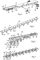
- the subframe 5 is shown in closer detail in Figs 2 and 3 .
- the subframe 5 is to be mounted to the chassis 3 closely behind the driver's cabin.
- a recess 6 is provided on the underside of the subframe 5 at the front end 7 thereof, i.e. at the end that is intended to face the driver's cabin.
- This recess 6 is provided in the subframe 5 in order to prevent the subframe from interfering mechanically with components (not shown) of the lorry 1 which extend beyond the rear end of the driver's cabin. Due to this recess 6, the subframe 5 has a weakened section 8 at its front end 7. This weakened section 8 has reduced strength as compared to the adjacent section 9 of the subframe 5.
- the loader crane 4 is a hydraulic crane of conventional type and comprises:
- the column 11 and the crane booms 13, 14, 15 are hydraulically actuated.
- the crane base 10 is secured to the subframe 5 by a non-yielding first bolted joint 16a and a non-yielding second bolted joint 16b.
- the first and second bolted joints 16a, 16b are arranged on opposite sides of the subframe 5 and configured to form a stiff connection between the crane base 10 and the subframe 5. Due to the stiff connection established between the crane base 10 and the subframe 5 by the bolted joints 16a, 16b, the weakened section 8 of the subframe 5 is reinforced by the crane base 10.
- Each one of the bolted joints 16a, 16b comprises several bolts 17 distributed in the longitudinal direction of the subframe 5, wherein each bolted joint 16a, 16b preferably comprises at least six bolts 17, most preferably at least eight bolts 17, arranged behind each other in a row in the longitudinal direction of the subframe 5.
- the suitable number of bolts 17 of the first and second bolted joints 16a, 16b depends on the size and the weight of the loader crane 4.
- the first bolted joint 16a comprises eight bolts 17 arranged in a row
- the second bolted joint 16b comprises ten bolts 17 arranged in a row.
- the first bolted joint 16a comprises an elongated first support member 18a which is provided with through holes 19 for the bolts 17 of the first bolted joint and which is rigidly fixed to the subframe 5, preferably by welding, so as to extend in the longitudinal direction of the subframe 5.
- the first support member 18a is fixed to a first vertical and longitudinal side wall 20a of the subframe 5 and projects laterally from this first side wall 20a.
- the through holes 19 of the first support member 18a are aligned with corresponding bolt holes 21a (see Fig 10 ) provided on the underside of the crane base 10.
- the second bolted joint 16b comprises an elongated second support member 18b (see Fig 7 ) which is provided with through holes 19 for the bolts 17 of the second bolted joint and which is rigidly fixed to the subframe 5, preferably by welding, so as to extend in the longitudinal direction of the subframe 5.
- the second support member 18b is fixed to a second vertical and longitudinal side wall 20b of the subframe 5 located opposite said first side wall 20a, the second support member 18b projecting laterally from this second side wall 20b.
- the through holes 19 of the second support member 18b are aligned with corresponding bolt holes 21b provided on the underside of the crane base 10.
- each support member 18a, 18b comprises a horizontal plate-shaped base part 22a, 22b, which is elongated and provided with the trough holes 19 for the bolts 17, and several vertical support elements 23 for supporting the base part 22a, 22b in relation to the associated side wall 20a, 20b of the subframe 5.
- Each one of said through holes 19 of the first and second support members 18a, 18b preferably has an oblong cross-sectional shape with a main extension in a direction perpendicular to the longitudinal axis of the associated support member 18a, 18b.
- dual washers 24 are with advantage provided between the first support member 18a and the heads 25 of the bolts 17 received in the through holes 19 of the first support member 18a and between the second support member 18b and the heads 25 of the bolts 17 received in the through holes 19 of the second support member 18b.
- Each one of these dual washers 24 has a circular first through hole 26a for receiving the bolt shaft 27 of one of said bolts 17 and a circular second through hole 26b for receiving the bolt shaft 27 of another one of said bolts 17.
- the first and second through holes 26a, 26b of a dual washer 24 are located in two separate parts 28a, 28b of the washer which are connected to each other by a connecting piece 29 so as to form a recess 30 between the two parts 28a, 28b and thereby enable these two parts 28a, 28b to be positioned on either side of one of the above-mentioned support elements 23.
- a lock washer 31 is with advantage arranged between the head 25 of each bolt 17 and the associated washer 24.
- dual washers 24 it is of course also possible to use single-type washers with only one through hole for the bolt shaft 27 of a bolt 17.
- each one of the above-mentioned bolt holes 21a, 21b on the crane base 10 is provided with an internal thread 33 (see Figs 9 and 12 ) configured for engagement with an external thread 34 provided on the bolt shaft 27 of an associated bolt 17.
- the first bolted joint 16a comprises an elongated first mounting member 35a (see Figs 9-12 ) in the form of a bar or a plate, which is rigidly fixed to the crane base 10 on the underside thereof, preferably by welding, and which is provided with the threaded bolt holes 21a for the bolts 17 of the first bolted joint.
- the second bolted joint 16b comprises an elongated second mounting member 35b in the form of a bar or a plate, which is rigidly fixed to the crane base 10 on the underside thereof, preferably by welding, and which is provided with the threaded bolt holes 21b for the bolts 17 of the second bolted joint.
- the mounting members 35a, 35b project downwards from a bottom plate 36 of the crane base 10, this bottom plate 36 being configured to rest against an upper surface 37 of the subframe 5 when the crane base 10 has been mounted to the subframe.
- the support members 18a, 18b are preferably fixed to the subframe 5 at such a height that there remains a small gap 38 between the upper surface of each support member 18a, 18b and the lower surface of the associated mounting member 35a, 35b when a suitable tightening torque has been applied to the bolts 17 of the bolted joints, as illustrated in Fig 12 .
- each one of said shear-yielding connecting elements 40 comprises a first holding member 41 (see Fig 8 ) fixed to the subframe 5, a second holding member 42 fixed to the chassis 3 and an elongated connecting member 43 extending between the first and second holding members 41, 42.
- the first holding member 41 may be fixed to one of the above-mentioned longitudinal side walls 20a, 20b of the subframe 5, as illustrated in Fig 8 .
- each holding member 41, 42 comprises a plate-shaped first part 41a, 42a and a second part 41b, 42b which is fixed to the first part and projects laterally therefrom.
- the first part 41a of the first holding member 41 is preferably fixed to the subframe 5 by welding and the first part 42a of the second holding member 42 is fixed to the chassis 3 by means of bolts 44 or by welding.
- the connecting member 43 has a circular cross-sectional shape.
- the connecting member 43 has the form of a bolt with a bolt head which rests against the second part 41b, 42b of one of the holding members 41, 42 and with a bolt shaft which extends through a through hole in the second part 41b of the first holding member 41 and through an opposite through hole in the second part 42b of the second holding member 42, wherein the connecting member 43 is fixed to the holding members 41, 42 by means of a nut 45 engaged with an external thread at the end of the bolt shaft.
- the subframe 5 the components of the first and second bolted joints 16a, 16b and the components of the shear-yielding connecting elements 40 are of metallic material, for instance steel.
- the first and second support members 18a, 18b included in the first and second bolted joints 16a, 16b and the first holding members 41 included in the shear-yielding connecting elements 40 are in a first step fixed to the subframe 5 by welding, as illustrated in Fig 4 .
- the cross bar 51 of a support leg arrangement 50 is also fixed to the subframe 5 by welding in this first step.
- This first step may be carried out at the assembly site before the loader crane 4 has been delivered at the assembly site. Furthermore, all the welding zones on the subframe 5 are easily accessible since no loader crane is positioned on the subframe when the welding work is carried out.
- the welded assembly may be painted in a second step.
- the subframe 5 is fixed to the chassis 3 by means of the shear-yielding connecting elements 40, as illustrated in Fig 8 , or by means of any other suitable type of connecting elements.
- the crane base 10 is fixed to the subframe 5 by means of the first and second bolted joints 16a, 16b.
- the crane base 10 may be fixed to the subframe 5 by means of the bolted joints 16a, 16b before the subframe 5 is fixed to the chassis 3.
Landscapes
- Engineering & Computer Science (AREA)
- Transportation (AREA)
- Mechanical Engineering (AREA)
- Chemical & Material Sciences (AREA)
- Combustion & Propulsion (AREA)
- Jib Cranes (AREA)
- Body Structure For Vehicles (AREA)
Claims (13)
- Camion comprenant :- un châssis (3) ;- un sous-châssis (5) qui est monté sur le châssis (3) et qui a une section affaiblie (8) à son extrémité avant (7) en raison d'un évidement (6) prévu sur le dessous du sous-châssis (5) à l'extrémité avant (7) de celui-ci qui est destinée à faire face à la cabine du conducteur du camion, cette section affaiblie (8) ayant une force réduite par rapport à une section adjacente (9) du sous-châssis (5) ; et- une grue de chargement (4), qui est pourvue d'une base de grue (10) montée sur le sous-châssis (5) à l'extrémité avant (7) de celui-ci, la base de grue (10) étant sécurisée au sous-châssis (5) par au moins un premier raccord boulonné non élastique (16a) et un deuxième raccord boulonné non élastique (16b) qui sont agencés sur des côtés opposés du sous-châssis (5) et configurés pour former un raccordement rigide entre la base de grue (10) et le sous-châssis (5) de sorte que la section affaiblie (8) du sous-châssis (5) soit renforcée par la base de grue (10), dans lequel chacun de ces raccords boulonnés (16a, 16b) comprend plusieurs boulons (17) répartis dans la direction longitudinale du sous-châssis (5).
- Camion selon la revendication 1, caractérisé en ce que le sous-châssis (5) est sécurisé au châssis (3) au moyen d'éléments de raccordement déformables en cisaillement (40) qui sont configurés pour former un raccordement souple entre le sous-châssis (5) et le châssis (3).
- Camion selon la revendication 2, caractérisé en ce que chacun desdits éléments de raccordement déformables en cisaillement (40) comprend un premier organe de maintien (41) fixé au sous-châssis (5), un deuxième organe de maintien (42) fixé au châssis (3) et un organe de raccordement allongé (43), ayant une première extrémité et une deuxième extrémité opposée et s'étendant entre les premier et deuxième organes de maintien (41, 42), dans lequel l'organe de raccordement (43) à sa première extrémité est fixé au premier organe de maintien (41) et à sa deuxième extrémité est fixé au deuxième organe de maintien (42).
- Camion selon la revendication 3, caractérisé en ce que ledit premier organe de maintien (41) est fixé au sous-châssis (5) par soudage.
- Camion selon l'une quelconque des revendications 1 à 4, caractérisé en ce que chacun des raccords boulonnés (16a, 16b) comprend au moins six boulons (17), de préférence au moins huit boulons (17), agencés l'un derrière l'autre en ligne dans la direction longitudinale du sous-châssis (5).
- Camion selon l'une quelconque des revendications 1 à 5, caractérisé en ce que :- ledit premier raccord boulonné (16a) comprend un premier organe de support allongé (18a) qui est pourvu de trous traversants (19) pour les boulons (17) du premier raccord boulonné et qui est fixé rigidement au sous-châssis (5) de manière à s'étendre dans la direction longitudinale de celui-ci, dans lequel lesdits trous traversants (19) du premier organe de support (18a) sont alignés avec des trous de boulon correspondants (21a) prévus sur la base de grue (10) ; et- ledit deuxième raccord boulonné (16b) comprend un deuxième organe de support allongé (18b) qui est pourvu de trous traversants (19) pour les boulons (17) du deuxième raccord boulonné et qui est fixé rigidement au sous-châssis (5) de manière à s'étendre dans la direction longitudinale de celui-ci, dans lequel lesdits trous traversants (19) du deuxième organe de support (18b) sont alignés avec des trous de boulon correspondants (21b) prévus sur la base de grue (10).
- Camion selon la revendication 6, caractérisé en ce que chacun desdits trous traversants (19) du premier organe de support (18a) a une forme de coupe transversale oblongue avec une extension principale dans une direction perpendiculaire à l'axe longitudinal du premier organe de support (18a).
- Camion selon la revendication 7, caractérisé en ce que des rondelles doubles (24) sont prévues entre le premier organe de support (18a) et les têtes (25) des boulons (17) reçus dans les trous traversants (19) du premier organe de support, dans lequel chacune de ces rondelles doubles (24) a un premier trou traversant circulaire (26a) pour recevoir la tige de boulon (27) de l'un desdits boulons (17), et un deuxième trou traversant circulaire (26b) pour recevoir la tige de boulon (27) d'un autre desdits boulons (17).
- Camion selon l'une quelconque des revendications 6 à 8, caractérisé en ce que chacun desdits trous traversants (19) du deuxième organe de support (18b) a une forme de coupe transversale oblongue avec une extension principale dans une direction perpendiculaire à l'axe longitudinal du deuxième organe de support (18b).
- Camion selon la revendication 9, caractérisé en ce que des rondelles doubles (24) sont prévues entre le deuxième organe de support (18b) et les têtes (25) des boulons (17) reçus dans les trous traversants (19) du deuxième organe de support, dans lequel chacune de ces rondelles doubles (24) a un premier trou traversant circulaire (26a) pour recevoir la tige de boulon (27) de l'un desdits boulons (17) et un deuxième trou traversant circulaire (26b) pour recevoir la tige de boulon (27) d'un autre desdits boulons (17).
- Camion selon l'une quelconque des revendications 6 à 10, caractérisé en ce que chacun desdits trous de boulon (21a, 21b) sur la base de grue (10) est pourvu d'un filetage interne (33) configuré pour se mettre en prise avec un filetage externe (34) sur la tige de boulon (27) d'un boulon associé (17).
- Camion selon la revendication 11, caractérisé en ce que :- ledit premier raccord boulonné (16a) comprend un premier organe de montage allongé (35a) sous la forme d'une barre ou d'une plaque, qui est fixé rigidement à la base de grue (10) sur le dessous de celle-ci et qui est pourvu de trous de boulon filetés (21a) pour les boulons (17) du premier raccord boulonné ; et- ledit deuxième raccord boulonné (16b) comprend un deuxième organe de montage allongé (35b) sous la forme d'une barre ou d'une plaque, qui est fixé rigidement à la base de grue (10) sur le dessous de celle-ci et qui est pourvu de trous de boulon filetés (21b) pour les boulons (17) du deuxième raccord boulonné.
- Camion selon l'une quelconque des revendications 6 à 12, caractérisé en ce que les premier et deuxième organes de support (18a, 18b) sont fixés au sous-châssis (5) par soudage.
Applications Claiming Priority (1)
| Application Number | Priority Date | Filing Date | Title |
|---|---|---|---|
| PCT/SE2014/051082 WO2016043636A1 (fr) | 2014-09-19 | 2014-09-19 | Camion doté d'une grue de chargement |
Publications (3)
| Publication Number | Publication Date |
|---|---|
| EP3194207A1 EP3194207A1 (fr) | 2017-07-26 |
| EP3194207A4 EP3194207A4 (fr) | 2018-05-09 |
| EP3194207B1 true EP3194207B1 (fr) | 2019-12-25 |
Family
ID=55533559
Family Applications (1)
| Application Number | Title | Priority Date | Filing Date |
|---|---|---|---|
| EP14901853.3A Active EP3194207B1 (fr) | 2014-09-19 | 2014-09-19 | Camion doté d'une grue de chargement |
Country Status (3)
| Country | Link |
|---|---|
| EP (1) | EP3194207B1 (fr) |
| DK (1) | DK3194207T3 (fr) |
| WO (1) | WO2016043636A1 (fr) |
Cited By (2)
| Publication number | Priority date | Publication date | Assignee | Title |
|---|---|---|---|---|
| EP4079573A1 (fr) * | 2021-04-22 | 2022-10-26 | WERKHUIZEN JACOBS, besloten vennootschap met beperkte aansprakelijkheid | Camion équipé d'une grue à chargeur automatique et grue à chargeur automatique applicable à celui-ci et son utilisation |
| FR3161159A1 (fr) * | 2024-04-16 | 2025-10-17 | May Concept Techs | Faux-châssis d’équipements de véhicule utilitaire |
Families Citing this family (2)
| Publication number | Priority date | Publication date | Assignee | Title |
|---|---|---|---|---|
| AT16249U1 (de) * | 2018-04-26 | 2019-05-15 | Fmg Fahrzeugbau Maschb Gmbh | Fahrzeug |
| FR3098486A1 (fr) * | 2019-07-10 | 2021-01-15 | Maycar | Interface de bridage équipement sur châssis de véhicule routier |
Family Cites Families (5)
| Publication number | Priority date | Publication date | Assignee | Title |
|---|---|---|---|---|
| SE340570B (fr) * | 1970-03-31 | 1971-11-22 | Hiab Foco Ab | |
| DE29800368U1 (de) * | 1998-01-12 | 1998-07-09 | Doll Fahrzeugbau Gmbh, 77728 Oppenau | Geschraubter Hilfsrahmen |
| SE525475C2 (sv) * | 2003-07-08 | 2005-03-01 | Volvo Lastvagnar Ab | System för anslutning av påbyggnader till ett lastfordon och anordning ingående i systemet |
| ATE482130T1 (de) * | 2008-01-07 | 2010-10-15 | Werkhuizen Jacobs Nv | Hilfsrahmen zur montage eines krans auf einem fahrgestell |
| DE102009047458B4 (de) * | 2009-12-03 | 2023-05-17 | Franz Xaver Meiller Fahrzeug- Und Maschinenfabrik - Gmbh & Co Kg | Befestigungsanordnung zur Anbringung eines Ladekrans an einem Lastkraftwagen |
-
2014
- 2014-09-19 WO PCT/SE2014/051082 patent/WO2016043636A1/fr not_active Ceased
- 2014-09-19 EP EP14901853.3A patent/EP3194207B1/fr active Active
- 2014-09-19 DK DK14901853.3T patent/DK3194207T3/da active
Non-Patent Citations (1)
| Title |
|---|
| None * |
Cited By (3)
| Publication number | Priority date | Publication date | Assignee | Title |
|---|---|---|---|---|
| EP4079573A1 (fr) * | 2021-04-22 | 2022-10-26 | WERKHUIZEN JACOBS, besloten vennootschap met beperkte aansprakelijkheid | Camion équipé d'une grue à chargeur automatique et grue à chargeur automatique applicable à celui-ci et son utilisation |
| BE1029334B1 (nl) * | 2021-04-22 | 2022-11-28 | Werkhuizen Jacobs | Vrachtwagen uitgerust met een autolaadkraan en autolaadkraan daarbij toepasbaar en gebruik ervan |
| FR3161159A1 (fr) * | 2024-04-16 | 2025-10-17 | May Concept Techs | Faux-châssis d’équipements de véhicule utilitaire |
Also Published As
| Publication number | Publication date |
|---|---|
| EP3194207A4 (fr) | 2018-05-09 |
| EP3194207A1 (fr) | 2017-07-26 |
| DK3194207T3 (da) | 2020-03-09 |
| WO2016043636A1 (fr) | 2016-03-24 |
Similar Documents
| Publication | Publication Date | Title |
|---|---|---|
| EP3194207B1 (fr) | Camion doté d'une grue de chargement | |
| JP4411303B2 (ja) | 建設機械におけるキャブ支持上部フレーム構造 | |
| RU2012141680A (ru) | Панельная палубная сборка для транспортера транспортного средства | |
| EP3774501B1 (fr) | Structure de carrosserie pour véhicule | |
| EP3069925B1 (fr) | Camion avec sous-châssis | |
| EP3617499B1 (fr) | Transport d'un composant d'éolienne | |
| US20220316202A1 (en) | Column-to-beam connection systems including a shear component | |
| CN105829195A (zh) | 以受剪区形式的车辆加固结构 | |
| US8047311B2 (en) | Method of retaining structural transmission members | |
| CA2877247C (fr) | Attache de remorquage avec traverse | |
| JP2021524552A (ja) | 車両拘束システム用の垂直部材 | |
| EP2915771B1 (fr) | Structure de protection de type bavette pour chariot élévateur à fourche | |
| CN102602461A (zh) | 工程机械驾驶室 | |
| JP7034282B2 (ja) | ミキサー車 | |
| AU2015101794A4 (en) | Chassis Assembly | |
| CN112829833B (zh) | 机动车 | |
| US20170107689A1 (en) | Support structure for frame of a machine | |
| GB2445449A (en) | A hardware mount for an automotive body structure | |
| JP5851315B2 (ja) | 足場金具およびその取付け方法 | |
| EP2930087B1 (fr) | Support amélioré pour un garde-boue | |
| CN222138595U (zh) | 用于车辆的护顶架及叉车 | |
| CN203905080U (zh) | 工程机械配重安装装置 | |
| CN106224062A (zh) | 汽车及其后处理装置 | |
| RU2522463C2 (ru) | Способ усиления центральной стойки кузова и места крепления двери атомобиля при бронировании | |
| KR100726516B1 (ko) | 자동차의 파워플랜트 장착구조 |
Legal Events
| Date | Code | Title | Description |
|---|---|---|---|
| STAA | Information on the status of an ep patent application or granted ep patent |
Free format text: STATUS: THE INTERNATIONAL PUBLICATION HAS BEEN MADE |
|
| PUAI | Public reference made under article 153(3) epc to a published international application that has entered the european phase |
Free format text: ORIGINAL CODE: 0009012 |
|
| STAA | Information on the status of an ep patent application or granted ep patent |
Free format text: STATUS: REQUEST FOR EXAMINATION WAS MADE |
|
| 17P | Request for examination filed |
Effective date: 20170217 |
|
| AK | Designated contracting states |
Kind code of ref document: A1 Designated state(s): AL AT BE BG CH CY CZ DE DK EE ES FI FR GB GR HR HU IE IS IT LI LT LU LV MC MK MT NL NO PL PT RO RS SE SI SK SM TR |
|
| AX | Request for extension of the european patent |
Extension state: BA ME |
|
| DAX | Request for extension of the european patent (deleted) | ||
| A4 | Supplementary search report drawn up and despatched |
Effective date: 20180411 |
|
| RIC1 | Information provided on ipc code assigned before grant |
Ipc: B66C 23/44 20060101ALI20180405BHEP Ipc: B62D 33/077 20060101ALI20180405BHEP Ipc: B62D 21/09 20060101ALI20180405BHEP Ipc: B62D 21/12 20060101ALI20180405BHEP Ipc: B60P 1/54 20060101AFI20180405BHEP |
|
| RIC1 | Information provided on ipc code assigned before grant |
Ipc: B66C 23/44 20060101ALI20190523BHEP Ipc: B62D 21/09 20060101ALI20190523BHEP Ipc: B60P 1/54 20060101AFI20190523BHEP Ipc: B62D 33/077 20060101ALI20190523BHEP Ipc: B62D 21/12 20060101ALI20190523BHEP |
|
| GRAP | Despatch of communication of intention to grant a patent |
Free format text: ORIGINAL CODE: EPIDOSNIGR1 |
|
| STAA | Information on the status of an ep patent application or granted ep patent |
Free format text: STATUS: GRANT OF PATENT IS INTENDED |
|
| INTG | Intention to grant announced |
Effective date: 20190712 |
|
| GRAS | Grant fee paid |
Free format text: ORIGINAL CODE: EPIDOSNIGR3 |
|
| GRAA | (expected) grant |
Free format text: ORIGINAL CODE: 0009210 |
|
| STAA | Information on the status of an ep patent application or granted ep patent |
Free format text: STATUS: THE PATENT HAS BEEN GRANTED |
|
| AK | Designated contracting states |
Kind code of ref document: B1 Designated state(s): AL AT BE BG CH CY CZ DE DK EE ES FI FR GB GR HR HU IE IS IT LI LT LU LV MC MK MT NL NO PL PT RO RS SE SI SK SM TR |
|
| RAP1 | Party data changed (applicant data changed or rights of an application transferred) |
Owner name: CARGOTEC PATENTER AB |
|
| REG | Reference to a national code |
Ref country code: GB Ref legal event code: FG4D |
|
| REG | Reference to a national code |
Ref country code: CH Ref legal event code: EP |
|
| REG | Reference to a national code |
Ref country code: AT Ref legal event code: REF Ref document number: 1216793 Country of ref document: AT Kind code of ref document: T Effective date: 20200115 |
|
| REG | Reference to a national code |
Ref country code: DE Ref legal event code: R096 Ref document number: 602014059138 Country of ref document: DE |
|
| REG | Reference to a national code |
Ref country code: IE Ref legal event code: FG4D |
|
| REG | Reference to a national code |
Ref country code: DK Ref legal event code: T3 Effective date: 20200305 |
|
| REG | Reference to a national code |
Ref country code: NL Ref legal event code: MP Effective date: 20191225 |
|
| PG25 | Lapsed in a contracting state [announced via postgrant information from national office to epo] |
Ref country code: LV Free format text: LAPSE BECAUSE OF FAILURE TO SUBMIT A TRANSLATION OF THE DESCRIPTION OR TO PAY THE FEE WITHIN THE PRESCRIBED TIME-LIMIT Effective date: 20191225 Ref country code: SE Free format text: LAPSE BECAUSE OF FAILURE TO SUBMIT A TRANSLATION OF THE DESCRIPTION OR TO PAY THE FEE WITHIN THE PRESCRIBED TIME-LIMIT Effective date: 20191225 Ref country code: NO Free format text: LAPSE BECAUSE OF FAILURE TO SUBMIT A TRANSLATION OF THE DESCRIPTION OR TO PAY THE FEE WITHIN THE PRESCRIBED TIME-LIMIT Effective date: 20200325 Ref country code: GR Free format text: LAPSE BECAUSE OF FAILURE TO SUBMIT A TRANSLATION OF THE DESCRIPTION OR TO PAY THE FEE WITHIN THE PRESCRIBED TIME-LIMIT Effective date: 20200326 Ref country code: LT Free format text: LAPSE BECAUSE OF FAILURE TO SUBMIT A TRANSLATION OF THE DESCRIPTION OR TO PAY THE FEE WITHIN THE PRESCRIBED TIME-LIMIT Effective date: 20191225 Ref country code: FI Free format text: LAPSE BECAUSE OF FAILURE TO SUBMIT A TRANSLATION OF THE DESCRIPTION OR TO PAY THE FEE WITHIN THE PRESCRIBED TIME-LIMIT Effective date: 20191225 Ref country code: BG Free format text: LAPSE BECAUSE OF FAILURE TO SUBMIT A TRANSLATION OF THE DESCRIPTION OR TO PAY THE FEE WITHIN THE PRESCRIBED TIME-LIMIT Effective date: 20200325 |
|
| REG | Reference to a national code |
Ref country code: LT Ref legal event code: MG4D |
|
| PG25 | Lapsed in a contracting state [announced via postgrant information from national office to epo] |
Ref country code: HR Free format text: LAPSE BECAUSE OF FAILURE TO SUBMIT A TRANSLATION OF THE DESCRIPTION OR TO PAY THE FEE WITHIN THE PRESCRIBED TIME-LIMIT Effective date: 20191225 Ref country code: RS Free format text: LAPSE BECAUSE OF FAILURE TO SUBMIT A TRANSLATION OF THE DESCRIPTION OR TO PAY THE FEE WITHIN THE PRESCRIBED TIME-LIMIT Effective date: 20191225 |
|
| PG25 | Lapsed in a contracting state [announced via postgrant information from national office to epo] |
Ref country code: AL Free format text: LAPSE BECAUSE OF FAILURE TO SUBMIT A TRANSLATION OF THE DESCRIPTION OR TO PAY THE FEE WITHIN THE PRESCRIBED TIME-LIMIT Effective date: 20191225 |
|
| PG25 | Lapsed in a contracting state [announced via postgrant information from national office to epo] |
Ref country code: NL Free format text: LAPSE BECAUSE OF FAILURE TO SUBMIT A TRANSLATION OF THE DESCRIPTION OR TO PAY THE FEE WITHIN THE PRESCRIBED TIME-LIMIT Effective date: 20191225 Ref country code: EE Free format text: LAPSE BECAUSE OF FAILURE TO SUBMIT A TRANSLATION OF THE DESCRIPTION OR TO PAY THE FEE WITHIN THE PRESCRIBED TIME-LIMIT Effective date: 20191225 Ref country code: RO Free format text: LAPSE BECAUSE OF FAILURE TO SUBMIT A TRANSLATION OF THE DESCRIPTION OR TO PAY THE FEE WITHIN THE PRESCRIBED TIME-LIMIT Effective date: 20191225 Ref country code: CZ Free format text: LAPSE BECAUSE OF FAILURE TO SUBMIT A TRANSLATION OF THE DESCRIPTION OR TO PAY THE FEE WITHIN THE PRESCRIBED TIME-LIMIT Effective date: 20191225 Ref country code: PT Free format text: LAPSE BECAUSE OF FAILURE TO SUBMIT A TRANSLATION OF THE DESCRIPTION OR TO PAY THE FEE WITHIN THE PRESCRIBED TIME-LIMIT Effective date: 20200520 |
|
| PG25 | Lapsed in a contracting state [announced via postgrant information from national office to epo] |
Ref country code: IS Free format text: LAPSE BECAUSE OF FAILURE TO SUBMIT A TRANSLATION OF THE DESCRIPTION OR TO PAY THE FEE WITHIN THE PRESCRIBED TIME-LIMIT Effective date: 20200425 Ref country code: SK Free format text: LAPSE BECAUSE OF FAILURE TO SUBMIT A TRANSLATION OF THE DESCRIPTION OR TO PAY THE FEE WITHIN THE PRESCRIBED TIME-LIMIT Effective date: 20191225 Ref country code: SM Free format text: LAPSE BECAUSE OF FAILURE TO SUBMIT A TRANSLATION OF THE DESCRIPTION OR TO PAY THE FEE WITHIN THE PRESCRIBED TIME-LIMIT Effective date: 20191225 |
|
| REG | Reference to a national code |
Ref country code: DE Ref legal event code: R097 Ref document number: 602014059138 Country of ref document: DE |
|
| PG25 | Lapsed in a contracting state [announced via postgrant information from national office to epo] |
Ref country code: ES Free format text: LAPSE BECAUSE OF FAILURE TO SUBMIT A TRANSLATION OF THE DESCRIPTION OR TO PAY THE FEE WITHIN THE PRESCRIBED TIME-LIMIT Effective date: 20191225 |
|
| PLBE | No opposition filed within time limit |
Free format text: ORIGINAL CODE: 0009261 |
|
| STAA | Information on the status of an ep patent application or granted ep patent |
Free format text: STATUS: NO OPPOSITION FILED WITHIN TIME LIMIT |
|
| PG25 | Lapsed in a contracting state [announced via postgrant information from national office to epo] |
Ref country code: SI Free format text: LAPSE BECAUSE OF FAILURE TO SUBMIT A TRANSLATION OF THE DESCRIPTION OR TO PAY THE FEE WITHIN THE PRESCRIBED TIME-LIMIT Effective date: 20191225 |
|
| 26N | No opposition filed |
Effective date: 20200928 |
|
| PG25 | Lapsed in a contracting state [announced via postgrant information from national office to epo] |
Ref country code: PL Free format text: LAPSE BECAUSE OF FAILURE TO SUBMIT A TRANSLATION OF THE DESCRIPTION OR TO PAY THE FEE WITHIN THE PRESCRIBED TIME-LIMIT Effective date: 20191225 |
|
| REG | Reference to a national code |
Ref country code: DE Ref legal event code: R082 Ref document number: 602014059138 Country of ref document: DE Representative=s name: MANITZ FINSTERWALD PATENT- UND RECHTSANWALTSPA, DE Ref country code: DE Ref legal event code: R081 Ref document number: 602014059138 Country of ref document: DE Owner name: HIAB AB, SE Free format text: FORMER OWNER: CARGOTEC PATENTER AB, LJUNGBY, SE |
|
| PG25 | Lapsed in a contracting state [announced via postgrant information from national office to epo] |
Ref country code: MC Free format text: LAPSE BECAUSE OF FAILURE TO SUBMIT A TRANSLATION OF THE DESCRIPTION OR TO PAY THE FEE WITHIN THE PRESCRIBED TIME-LIMIT Effective date: 20191225 |
|
| REG | Reference to a national code |
Ref country code: CH Ref legal event code: PL |
|
| REG | Reference to a national code |
Ref country code: GB Ref legal event code: 732E Free format text: REGISTERED BETWEEN 20210513 AND 20210519 |
|
| REG | Reference to a national code |
Ref country code: AT Ref legal event code: PC Ref document number: 1216793 Country of ref document: AT Kind code of ref document: T Owner name: HIAB AB, SE Effective date: 20210511 |
|
| REG | Reference to a national code |
Ref country code: BE Ref legal event code: MM Effective date: 20200930 |
|
| PG25 | Lapsed in a contracting state [announced via postgrant information from national office to epo] |
Ref country code: LU Free format text: LAPSE BECAUSE OF NON-PAYMENT OF DUE FEES Effective date: 20200919 |
|
| PG25 | Lapsed in a contracting state [announced via postgrant information from national office to epo] |
Ref country code: IE Free format text: LAPSE BECAUSE OF NON-PAYMENT OF DUE FEES Effective date: 20200919 Ref country code: LI Free format text: LAPSE BECAUSE OF NON-PAYMENT OF DUE FEES Effective date: 20200930 Ref country code: BE Free format text: LAPSE BECAUSE OF NON-PAYMENT OF DUE FEES Effective date: 20200930 Ref country code: CH Free format text: LAPSE BECAUSE OF NON-PAYMENT OF DUE FEES Effective date: 20200930 |
|
| REG | Reference to a national code |
Ref country code: AT Ref legal event code: UEP Ref document number: 1216793 Country of ref document: AT Kind code of ref document: T Effective date: 20191225 |
|
| PG25 | Lapsed in a contracting state [announced via postgrant information from national office to epo] |
Ref country code: TR Free format text: LAPSE BECAUSE OF FAILURE TO SUBMIT A TRANSLATION OF THE DESCRIPTION OR TO PAY THE FEE WITHIN THE PRESCRIBED TIME-LIMIT Effective date: 20191225 Ref country code: MT Free format text: LAPSE BECAUSE OF FAILURE TO SUBMIT A TRANSLATION OF THE DESCRIPTION OR TO PAY THE FEE WITHIN THE PRESCRIBED TIME-LIMIT Effective date: 20191225 Ref country code: CY Free format text: LAPSE BECAUSE OF FAILURE TO SUBMIT A TRANSLATION OF THE DESCRIPTION OR TO PAY THE FEE WITHIN THE PRESCRIBED TIME-LIMIT Effective date: 20191225 |
|
| PG25 | Lapsed in a contracting state [announced via postgrant information from national office to epo] |
Ref country code: MK Free format text: LAPSE BECAUSE OF FAILURE TO SUBMIT A TRANSLATION OF THE DESCRIPTION OR TO PAY THE FEE WITHIN THE PRESCRIBED TIME-LIMIT Effective date: 20191225 |
|
| PGFP | Annual fee paid to national office [announced via postgrant information from national office to epo] |
Ref country code: GB Payment date: 20220920 Year of fee payment: 9 |
|
| PGFP | Annual fee paid to national office [announced via postgrant information from national office to epo] |
Ref country code: FR Payment date: 20220926 Year of fee payment: 9 |
|
| PGFP | Annual fee paid to national office [announced via postgrant information from national office to epo] |
Ref country code: DK Payment date: 20230927 Year of fee payment: 10 Ref country code: DE Payment date: 20230928 Year of fee payment: 10 |
|
| GBPC | Gb: european patent ceased through non-payment of renewal fee |
Effective date: 20230919 |
|
| PG25 | Lapsed in a contracting state [announced via postgrant information from national office to epo] |
Ref country code: GB Free format text: LAPSE BECAUSE OF NON-PAYMENT OF DUE FEES Effective date: 20230919 |
|
| PG25 | Lapsed in a contracting state [announced via postgrant information from national office to epo] |
Ref country code: GB Free format text: LAPSE BECAUSE OF NON-PAYMENT OF DUE FEES Effective date: 20230919 Ref country code: FR Free format text: LAPSE BECAUSE OF NON-PAYMENT OF DUE FEES Effective date: 20230930 |
|
| REG | Reference to a national code |
Ref country code: DE Ref legal event code: R081 Ref document number: 602014059138 Country of ref document: DE Owner name: HIAB AB, SE Free format text: FORMER OWNER: HIAB AB, KISTA, SE |
|
| REG | Reference to a national code |
Ref country code: DE Ref legal event code: R119 Ref document number: 602014059138 Country of ref document: DE |
|
| REG | Reference to a national code |
Ref country code: DK Ref legal event code: EBP Effective date: 20240930 |
|
| PG25 | Lapsed in a contracting state [announced via postgrant information from national office to epo] |
Ref country code: DE Free format text: LAPSE BECAUSE OF NON-PAYMENT OF DUE FEES Effective date: 20250401 |
|
| PG25 | Lapsed in a contracting state [announced via postgrant information from national office to epo] |
Ref country code: DK Free format text: LAPSE BECAUSE OF NON-PAYMENT OF DUE FEES Effective date: 20240930 |
|
| PGFP | Annual fee paid to national office [announced via postgrant information from national office to epo] |
Ref country code: IT Payment date: 20250922 Year of fee payment: 12 |
|
| PGFP | Annual fee paid to national office [announced via postgrant information from national office to epo] |
Ref country code: AT Payment date: 20250917 Year of fee payment: 12 |