EP3194264B1 - Schwingungsdämpfendes, lasterzeugendes flugzeugbetätigungssystem - Google Patents
Schwingungsdämpfendes, lasterzeugendes flugzeugbetätigungssystem Download PDFInfo
- Publication number
- EP3194264B1 EP3194264B1 EP15830342.0A EP15830342A EP3194264B1 EP 3194264 B1 EP3194264 B1 EP 3194264B1 EP 15830342 A EP15830342 A EP 15830342A EP 3194264 B1 EP3194264 B1 EP 3194264B1
- Authority
- EP
- European Patent Office
- Prior art keywords
- point
- gearbox
- actuator
- aircraft
- vibration
- Prior art date
- Legal status (The legal status is an assumption and is not a legal conclusion. Google has not performed a legal analysis and makes no representation as to the accuracy of the status listed.)
- Active
Links
Images


Classifications
-
- B—PERFORMING OPERATIONS; TRANSPORTING
- B64—AIRCRAFT; AVIATION; COSMONAUTICS
- B64C—AEROPLANES; HELICOPTERS
- B64C27/00—Rotorcraft; Rotors peculiar thereto
- B64C27/001—Vibration damping devices
-
- B—PERFORMING OPERATIONS; TRANSPORTING
- B64—AIRCRAFT; AVIATION; COSMONAUTICS
- B64C—AEROPLANES; HELICOPTERS
- B64C27/00—Rotorcraft; Rotors peculiar thereto
- B64C27/001—Vibration damping devices
- B64C2027/002—Vibration damping devices mounted between the rotor drive and the fuselage
-
- B—PERFORMING OPERATIONS; TRANSPORTING
- B64—AIRCRAFT; AVIATION; COSMONAUTICS
- B64C—AEROPLANES; HELICOPTERS
- B64C27/00—Rotorcraft; Rotors peculiar thereto
- B64C27/001—Vibration damping devices
- B64C2027/004—Vibration damping devices using actuators, e.g. active systems
-
- B—PERFORMING OPERATIONS; TRANSPORTING
- B64—AIRCRAFT; AVIATION; COSMONAUTICS
- B64C—AEROPLANES; HELICOPTERS
- B64C27/00—Rotorcraft; Rotors peculiar thereto
- B64C27/04—Helicopters
- B64C27/08—Helicopters with two or more rotors
- B64C27/10—Helicopters with two or more rotors arranged coaxially
Definitions
- the subject matter disclosed herein relates to an anti-vibration load generating aircraft actuation system and, more particularly, to an aircraft actuation system including single-point actuators configured to generate an anti-vibration load applicable to a gearbox to counter rotor induced vibration.
- An aircraft such as a helicopter, typically includes an airframe with a top portion at which a main rotor apparatus is rotatably supported and a tail portion at which a tail rotor apparatus is rotatably supported.
- the aircraft may further include a drive portion that drives rotation of main and tail rotors for flight operations. This rotation generates vibratory loads that are transmitted to the airframe and can cause discomfort to pilots, crewmen and passengers as well as damage.
- US 2010/0090055 A1 shows a pylon having six pylon mounting links for mounting the pylon to an airframe.
- Each link is considered “near-rigid" and has a spherical-bearing rod-end on both ends such that the link can only transmit axial loads.
- At least one of the links has a mass carried within the link and selectively moveable by an actuating means along the axis of the link in an oscillatory manner for attenuating vibrations traveling axially through the link.
- the actuating means may be an electromechanical, hydraulic, pneumatic, or piezoelectric system. By mounting each link in a selected orientation relative to the other links, the actuating means may be operated in a manner that attenuates axial vibration that would otherwise be transmitted through the link and into the airframe.
- EP 0 501 658 A1 shows a strut assembly including an axially elastically extensible tube having attachment means at each end and an axially extensible actuator attached within the tube and between its ends so that reciprocal axial extensions of the actuator cause elastic longitudinal displacements of the strut assembly.
- a strut assembly is particularly useful for transmitting operational loads between parts of a structure and for inputting periodic loads into one of the parts as part of an active vibration control system.
- EP 2 527 250 A1 shows an aircraft having a main gearbox fastened to a load-bearing structure via at least three suspension bars.
- Each suspension bar is provided with a vibration absorber including a first moving mass and a second moving mass.
- Moving masses are mounted to slide axially along an associated suspension bar, wherein the first mass is connected to the suspension bar via first resilient means.
- the second moving mass is connected to the first mass via resilient means.
- a force generator is then arranged between the first mass and the second mass to provide vibration reducing forces.
- US 6,145,785 shows an anti-vibration suspension device including three diagonal bars each articulated on the structure and on the transmission box by means of a rigid lever supporting a damping weight and itself articulated at least by pivoting on this box, and, for each diagonal bar, a tension bar also articulated on the structure and on the transmission box, the corresponding lever being articulated on the box while being articulated by at least pivoting on the upper end part of the corresponding tension bar, which is flexible in tension.
- an aircraft comprising the features of claim 1.
- the actuation system includes six single-point actuators respectively associated with one or more support members.
- At least one or more single-point actuators produce a corresponding portion of the anti-vibration load in a single direction.
- At least one or more single-point actuators produce a corresponding portion of the anti-vibration load in multiple directions.
- At least one or more single-point actuators apply a corresponding portion of the anti-vibration load to the gearbox directly.
- At least one or more of the support members includes a tubular cross-section with a single-point actuator disposed therein.
- At least one or more of the support members includes a beam-shaped cross-section with a single-point actuator disposed adjacent to support member.
- At least one or more of the support members includes a joint having more than one degree of freedom.
- vibration from main rotor(s) of an aircraft is transmitted to the fuselage and engine(s) and passengers via the main transmission. Nullifying the main transmission motion will cause vibration throughout the aircraft to be dramatically reduced thus improving aircraft reliability and passenger comfort.
- single-point actuators that incorporate an oscillating proof mass are attached to the main transmission or, alternatively, to the support members of the main transmission. In either case, anti-vibration loads created by the single-point actuators can be applied to the main transmission.
- the aircraft 10 includes an airframe 11 formed to define a cabin in which a pilot and, in some cases, a crew and passengers are accommodated, and housing a flight computer 12 (see FIG. 3 ).
- the airframe 11 includes a top portion 13 at which a main rotor apparatus 14 is rotatably supported and a tail portion 15 at which a tail rotor apparatus 16 is rotatably supported.
- the aircraft 10 may be configured as a coaxial, counter-rotating helicopter with the main rotor apparatus 14 including coaxial, counter rotating rotors 140 and 141, a gearbox 142 and support members 143, as shown in FIG.
- the aircraft 10 further includes a drive portion 20 including an engine 21 and a drive shaft 22.
- the engine 21 is configured to generate rotational energy, which is transmitted to the gearbox 142 by the drive shaft 22.
- the gearbox 142 then transmits the rotational energy to the coaxial, counter rotating rotors 140 and 141 to thereby drive rotation of the coaxial, counter rotating rotors 140 and 141 relative to the airframe 11.
- the main rotor apparatus 14 and the drive portion 20 may both be disposed at or near the top portion 13 of the airframe 11 with at least the gearbox 142 being supportively disposed on the airframe 11 at or near the top portion 13 by the support members 143.
- the support members 143 serve to secure the main rotor apparatus 14 to the airframe 11 in opposition to the steady lifting loads generated by the rotation of and lift loads produced by the coaxial, counter rotating rotors 140 and 141.
- Each of the coaxial, counter rotating rotors 140 and 141 includes a set of blades 30 that extend outwardly from a blade retention hub 31.
- the blade retention hubs 31 are each coupled to the gearbox 142 via rotor shafts 32.
- the blades 30 generate steady (i.e., the steady lifting loads noted above) and vibratory loads that are transmitted through the blade retention hubs 31 to the rotor shafts 32 and into the gearbox 142.
- the steady and vibratory loads are transmitted via the support members 143 into the fuselage of the airframe 11.
- Other vibratory loads can be transmitted from the gearbox 142 through the drive shaft 22 and into the engine 21.
- these other vibratory loads can be transmitted to the fuselage of the airframe 11 through engine supports 140A.
- the vibratory portion of the loads generated by the main rotor apparatus 14 may thus lead to vibration in the airframe 11 and the engine 21 causing fatigue to the pilot and any crew or passengers as well as possible damage to equipment mounted in the fuselage of the airframe 11.
- the aircraft 10 further includes an actuation system 40.
- the actuation system 40 is operably coupled to a vibration control computer 120 and includes single-point actuators 41.
- the single-point actuators 41 are configured to generate an anti-vibration load that is applicable to the gearbox 142 to counter vibratory portion of the loads generated by rotation of the coaxial, counter rotating rotors 140 and 141 of the main rotor apparatus 14.
- the vibration control computer 120 identifies the presence and direction of the vibratory portion of the loads being applied to the gearbox 142 and controls operations of the single-point actuators 41 accordingly.
- the vibration control computer 120 of the flight computer 12 senses or otherwise measures the magnitude and phase of the vibratory accelerations in the fuselage 11 caused by loads applied to the gearbox 142 by the main rotor apparatus 14 due to the sum loads originating from the coaxial, counter-rotating rotors 140 and 141 (operation 50). These accelerations may be sensed or detected by a series of accelerometers 1200 coupled to the vibration control computer 120 and disposed in or about the fuselage 11. The vibration control computer 120 then calculates a magnitude and phase of the anti-vibration load required to counter the accelerations in the fuselage (operation 51) and controls operations of the single-point actuators 41 accordingly (operation 52). The vibration control computer 120 may further determine whether vibration in the airframe 11 and the engine 21 are sufficiently reduced and may adjust the control of the single-point actuators 41 if results of that determination indicate that excessive vibration remains.
- the support members 143 may be provided in a group of at least 6 support members 143 or as a mixture of support members 143 and other types of support elements, such as plates. In any case, the support members 143 may be disposed to restrain the gearbox 142 in six directions respectively associated with six degrees of freedom. Where the support members 143 are provided in a group of six, the single-point actuators 41 may also be provided in a group of six single-point actuators 41. However, it is to be understood that the number of the support members 143 and the number of the single-point actuators 41 need not be the same and each could be more or less than six.
- the vibratory loads applied to the gearbox 142 by the rotation of the coaxial, counter rotating rotors 140 and 141 of the main rotor apparatus 14 are countered by the single-point actuators 41 under the controls described above.
- the single-point actuators 41 are configured to produce anti-vibration loads that act at corresponding single points on the gearbox 142 and are not generated as a result of equal and opposite loads as would be created by a typical hydraulic ram type actuator.
- At least one or more of the single-point actuators 41 may be configured to produce a corresponding portion of the anti-vibration loads in a single direction.
- At least one or more of the single-point actuators 41 may be configured to produce a corresponding portion of the anti-vibration loads in a multiple directions.
- This corresponding portion of the anti-vibration loads may be referred to as a single-point load and can be created by oscillating an inertia or "proof mass" at a desired amplitude, phase and frequency and using the resulting inertial load(s) to counteract the gearbox motions caused by the vibratory loads applied to the gearbox 142 by the main rotors 30.
- the single-point actuators 41 include actuator elements 410, stinger elements 411 and mounting points 412.
- the actuator elements 410 are each disposed along a corresponding one of the support members 143 and are operably coupled to the vibration control computer 120.
- the actuator elements 410 thus generate the corresponding portion of the anti-vibration loads for the given single-point actuator 41 as an axial movement of a parasitic mass at the desired amplitude, phase and frequency in accordance with instructions received from the vibration control computer 120.
- the stinger elements 411 are each provided as an elongate component that extends axially from an end of the corresponding actuator element 410 to the corresponding mounting point 412, which is defined as a connection point between a support member 143 and the gearbox 142.
- the stinger element 411 thus transmits anti-vibration loads from the actuator element 410 to the mounting point 412 and allows the actuator 41 to be positioned remotely from the gearbox 142 to avoid mechanical interferences while still applying the load to the gearbox 142 instead of the support member 143.
- the corresponding portion of the anti-vibration load for the given single-point actuator 41 that is generated by the actuator element 410 is transmitted through the stinger element 411 to the stinger mounting point 412.
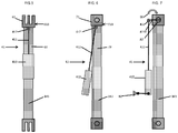
- the stinger mounting point 412 is coupled to the gearbox 142 directly such that the anti-vibration loads for the given single-point actuator 41 are applied proximate to an upper end of the support member 143 and to the gearbox 142 directly. Examples relating to the connections of a stinger mounting point 412, not covered by the appended claims, will be described in greater detail below with reference to FIGS. 5-7
- the support members 143 may include a tubular cross-section 60 and a joint element (or clevis) 61 by which the support member 143 is connected to the gearbox 142.
- the joint element 61 may have one or more degrees of freedom in the connection and may be provided, e.g., as a hinge-pin connection 610 (single degree of freedom) or as a ball-cuff connection (multiple degrees of freedom).
- a hinge-pin connection 610 single degree of freedom
- a ball-cuff connection multiple degrees of freedom
- the actuator element 410 may be disposed within or beside the tubular cross-section 60 with the stinger element 411 extending toward the joint element 61 at an end of the tubular cross-section 60 and with the stinger mounting point 412 positioned at the joint element 61.
- the stinger 411 may be substantially parallel with the tubular cross section 60.
- the stinger load is thus applied to the gearbox 142 to suppress gearbox motions.
- the effect on gearbox 142 motions is not sensitive to the orientation of the stinger 411.
- at least one or more of the support members 143 may include a beam-shaped (e.g., an I-beam-shaped) cross-section 70 and a joint element (or clevis) 71 by which the support member 143 is connected to the gearbox 142.
- the joint element 71 may have one or more degrees of freedom in the connection and may be provided, e.g., as a hinge-pin connection 710 (single degree of freedom) or as a ball-cuff connection (multiple degrees of freedom).
- the actuator element 410 may be disposed at an angle relative to the support member 143 and adjacent to the beam-shaped cross-section 70 with the stinger element 411 extending toward the joint element 71 at an end of the beam-shaped cross-section 70 and with the stinger mounting point 412 positioned at the joint element 71.
- the stinger 411 may be substantially non-parallel with the cross section 70 to react vibratory loads passing substantially non-parallel with the support member 143.
- the corresponding portions of the anti-vibration loads from the actuator elements 410 are oriented to pass through the connection points of the joint elements 61, 71 to the gearbox 142.
- the corresponding portion of the anti-vibration loads from an actuator element 410 can be oriented to create a moment 80.
- the actuator element 410 is mounted remotely from the support member 143 in a restraint element 81 that is configured to equilibrate moment 80.
- the stinger 411 has an extension 4110 between joint 82 and the stinger mounting point 412.
- the restraint element 81 can be mounted to, by way of example, the airframe 11 and maintains the orientation of the stinger 411 and actuator element 410 relative to the support member 143. In this manner, the stinger 411 is held apart from but substantially parallel to the support member 143, and the actuation of the actuator element 410 creates the moment 80.
- the restraint element 81 may be tuned such that the corresponding portion of the anti-vibration loads from the actuator element 410 is substantially reacted at the joint 82 with little, if any, reacted by the restraint 81. While shown as substantially parallel with the support member 143, it is understood that the restraint 81 could be moved relative to the stinger mounting point 412 such that the stinger 411 and actuator element 410 are substantially not parallel with the support member 143.
- additional anti-vibration actuators could be applied directly to the gearbox 142 and/or to attachments between the engine 20 and the airframe 11 to further reduce vibration.
Landscapes
- Engineering & Computer Science (AREA)
- Mechanical Engineering (AREA)
- Aviation & Aerospace Engineering (AREA)
- Vibration Prevention Devices (AREA)
Claims (8)
- Luftfahrzeug (10), umfassend:eine Luftfahrzeugzelle (11);einen Rotor (14), der relativ zu der Luftfahrzeugzelle (11) drehbar ist und der eine rotorinduzierte Schwingung erzeugt;einen Motor (21), um Drehenergie zu erzeugen;einen Antriebsabschnitt, um die Drehenergie von dem Motor (21) zu übermitteln;ein Getriebe (142), das angeordnet ist, um die Drehenergie von dem Antriebsabschnitt auf den Rotor (14) zu übertragen, um Rotordrehung anzutreiben;Stützelemente (143), die das Getriebe (142) mit der Luftfahrzeugzelle (11) verbinden; undein Betätigungssystem (40), das konfiguriert ist, um eine schwingungsdämpfende Last, die auf das Getriebe (142) anwendbar ist, über einen Aktuator zu erzeugen, der einen Einpunktaktuator (41) umfasst, wobei der Einpunktaktuator Folgendes umfasst:ein Aktuatorelement (410), das entlang einem der Stützelemente (143) angeordnet ist; undein Stingerelement (411), das sich von dem Aktuatorelement (410) zu einem Stingermontagepunkt (412) erstreckt, um einen Anteil der schwingungsdämpfenden Last von dem Aktuatorelement (410) auf den Stingermontagepunkt (412) zu übertragen, um der rotorinduzierten Schwingung an dem Getriebe (142) entgegenzuwirken; dadurch gekennzeichnet, dassder Stingermontagepunkt (412) ein Verbindungspunkt des Stützelements (143) und des Getriebes (142) ist und direkt an das Getriebe (142) gekoppelt ist, sodass schwingungsdämpfende Lasten für den Einpunktaktuator (41) in der Nähe eines oberen Endes des Stützelements (143) und direkt auf das Getriebe (142) aufgebracht werden.
- Luftfahrzeug (10) nach Anspruch 1, wobei das Betätigungssystem (40) sechs Einpunktaktuatoren (41) umfasst, die jeweils einem oder mehreren Stützelementen (143) zugeordnet sind.
- Luftfahrzeug (10) nach Anspruch 2, wobei zumindest ein oder mehrere Einpunktaktuatoren (41) einen entsprechenden Anteil der schwingungsdämpfenden Last in einer einzelnen Richtung produzieren.
- Luftfahrzeug (10) nach einem von Anspruch 2 oder 3, wobei zumindest ein oder mehrere Einpunktaktuatoren (41) einen entsprechenden Anteil der schwingungsdämpfenden Last in mehreren Richtungen produzieren.
- Luftfahrzeug (10) nach einem der Ansprüche 2-4, wobei zumindest ein oder mehrere Einpunktaktuatoren (41) einen entsprechenden Anteil der schwingungsdämpfenden Last direkt auf das Getriebe (142) aufbringen.
- Luftfahrzeug (10) nach einem der Ansprüche 2-5, wobei zumindest eines oder mehrere der Stützelemente (143) einen röhrenförmigen Querschnitt mit einem Einpunktaktuator (41) umfassen, der darin angeordnet ist.
- Luftfahrzeug (10) nach einem der Ansprüche 2-5, wobei zumindest eines oder mehrere der Stützelemente (143) einen balkenförmigen Querschnitt mit einem Einpunktaktuator (41) umfassen, der benachbart zu dem Stützelement (143) angeordnet ist.
- Luftfahrzeug (10) nach einem der Ansprüche 2-7, wobei zumindest eines oder mehrere der Stützelemente (143) ein Gelenk umfasst, das mehr als einen Freiheitsgrad aufweist.
Applications Claiming Priority (2)
| Application Number | Priority Date | Filing Date | Title |
|---|---|---|---|
| US201462034586P | 2014-08-07 | 2014-08-07 | |
| PCT/US2015/043793 WO2016022672A1 (en) | 2014-08-07 | 2015-08-05 | Anti-vibration load generating aircraft actuation system |
Publications (3)
| Publication Number | Publication Date |
|---|---|
| EP3194264A1 EP3194264A1 (de) | 2017-07-26 |
| EP3194264A4 EP3194264A4 (de) | 2018-03-21 |
| EP3194264B1 true EP3194264B1 (de) | 2022-06-22 |
Family
ID=55264491
Family Applications (1)
| Application Number | Title | Priority Date | Filing Date |
|---|---|---|---|
| EP15830342.0A Active EP3194264B1 (de) | 2014-08-07 | 2015-08-05 | Schwingungsdämpfendes, lasterzeugendes flugzeugbetätigungssystem |
Country Status (3)
| Country | Link |
|---|---|
| US (1) | US10745116B2 (de) |
| EP (1) | EP3194264B1 (de) |
| WO (1) | WO2016022672A1 (de) |
Families Citing this family (6)
| Publication number | Priority date | Publication date | Assignee | Title |
|---|---|---|---|---|
| EP3197771B1 (de) * | 2014-09-26 | 2019-06-26 | Sikorsky Aircraft Corporation | Schwingungsdämpfendes, momenterzeugendes flugzeugbetätigungssystem |
| US10160537B2 (en) * | 2017-03-13 | 2018-12-25 | The Boeing Company | Apparatus for using aircraft active vibration control system as pilot cueing aid |
| US20180265186A1 (en) | 2017-03-15 | 2018-09-20 | Bell Helicopter Textron Inc. | Vibration Isolation Systems for Advancing Blade Concept Rotorcraft |
| US11932380B2 (en) | 2017-03-15 | 2024-03-19 | Textron Innovations Inc. | Vibration isolation systems for compound helicopters |
| FR3063972A1 (fr) | 2017-03-20 | 2018-09-21 | Airbus Helicopters | Systemes antivibratoire equipant un giravion, giravion associe et methode de reglage d'un tel systeme antivibratoire. |
| KR102046106B1 (ko) * | 2018-10-12 | 2019-11-18 | 울산과학기술원 | 접이식 다중 회전익형 무인항공기 |
Family Cites Families (18)
| Publication number | Priority date | Publication date | Assignee | Title |
|---|---|---|---|---|
| FR2474996A1 (fr) * | 1980-02-05 | 1981-08-07 | Aerospatiale | Dispositif de suspension antiresonnante pour helicoptere |
| US5230407A (en) * | 1990-06-22 | 1993-07-27 | Applied Power Inc. | Linkage rod with shock absorbing |
| GB9104189D0 (en) * | 1991-02-28 | 1991-06-12 | Westland Helicopters | Active vibration control systems |
| GB9104190D0 (en) | 1991-02-28 | 1991-06-12 | Westland Helicopters | Strut assemblies |
| FR2680848B1 (fr) * | 1991-08-29 | 1995-03-17 | Aerospatiale Ste Nat Indle | Procede et dispositif pour filtrer les excitations vibratoires transmises entre deux pieces, notamment entre le rotor et le fuselage d'un helicoptere. |
| GB9124081D0 (en) | 1991-11-13 | 1992-09-23 | Westland Helicopters | Strut assemblies |
| US5310137A (en) | 1992-04-16 | 1994-05-10 | United Technologies Corporation | Helicopter active noise control system |
| FR2777860B1 (fr) * | 1998-04-23 | 2000-07-07 | Eurocopter France | Dispositif simplifie de suspension antivibratoire a batteurs hauts pour helicoptere |
| FR2787762B1 (fr) * | 1998-12-29 | 2001-03-09 | Eurocopter France | Dispositif de suspension antivibratoire avec ressort en torsion, pour helicoptere |
| US6644590B2 (en) * | 2000-09-15 | 2003-11-11 | General Dynamics Advanced Information Systems, Inc. | Active system and method for vibration and noise reduction |
| DE10154391A1 (de) | 2001-11-06 | 2003-05-22 | Eurocopter Deutschland | Vorrichtung und Verfahren zur Schwingungsisolation in einem Übertragungspfad |
| DE10358200B4 (de) | 2003-12-12 | 2010-06-24 | Eurocopter Deutschland Gmbh | Stabförmiges, hochbelastbares, aktives Verbindungselement sowie Drehflügelflugzeug mit einem solchen Verbindungselement |
| EP1724191B1 (de) * | 2005-05-16 | 2008-07-09 | Agusta S.p.A. | Hubschrauber mit verbesserter Schwingungskontrollvorrichtung |
| WO2008060681A2 (en) * | 2006-05-06 | 2008-05-22 | Lord Corporation | Helicopter reduced vibration isolator axial support strut |
| KR20090076903A (ko) * | 2006-10-12 | 2009-07-13 | 벨 헬리콥터 텍스트론 인크. | 진동 완화 강성 장착 파일런 |
| US20120292434A1 (en) | 2011-04-29 | 2012-11-22 | Sikorsky Aircraft Corporation | Six Degrees Of Freedom Vibration Suppression |
| FR2975668B1 (fr) * | 2011-05-27 | 2013-07-05 | Eurocopter France | Procede et aeronef muni d'un dispositif pour la reduction de vibrations |
| US9254914B2 (en) * | 2013-11-21 | 2016-02-09 | Bell Helicopter Textron Inc. | Helicopter transmission mount system |
-
2015
- 2015-08-05 EP EP15830342.0A patent/EP3194264B1/de active Active
- 2015-08-05 WO PCT/US2015/043793 patent/WO2016022672A1/en not_active Ceased
- 2015-08-05 US US15/501,240 patent/US10745116B2/en active Active
Also Published As
| Publication number | Publication date |
|---|---|
| EP3194264A4 (de) | 2018-03-21 |
| EP3194264A1 (de) | 2017-07-26 |
| WO2016022672A1 (en) | 2016-02-11 |
| US20170225774A1 (en) | 2017-08-10 |
| US10745116B2 (en) | 2020-08-18 |
Similar Documents
| Publication | Publication Date | Title |
|---|---|---|
| EP3194264B1 (de) | Schwingungsdämpfendes, lasterzeugendes flugzeugbetätigungssystem | |
| US7648338B1 (en) | Dual higher harmonic control (HHC) for a counter-rotating, coaxial rotor system | |
| US10065730B2 (en) | Active vibration control system with non-concentric revolving masses | |
| US8899928B2 (en) | Device for reducing the vibration generated by a rotorcraft lift rotor, and a rotor hub provided with such a device | |
| US20090116963A1 (en) | Active force generation system for minimizing vibration in a rotating system | |
| EP3375710B1 (de) | "advancing blade concept rotorcraft" mit einem schwingungsisolationssystem | |
| US10723450B2 (en) | Passive pitch angle adjustment apparatus | |
| EP2223854A1 (de) | Hubschrauberrotor | |
| EP3431392B1 (de) | Mit aktiver schwingungssteuerung erweiterte higher harmonic control | |
| US12319406B2 (en) | Vibration isolation systems for compound helicopters | |
| KR20150028729A (ko) | 기계 요소를 위한 방진 서스펜션 장치 및 항공기 | |
| CN108698686B (zh) | 用于能够悬停的飞行器的旋翼的减振装置和减振方法 | |
| US20110147512A1 (en) | Rotor carrier structure, a flying machine provided with such a carrier structure, and a method of avoiding unstable coupling between resonant vibration modes | |
| EP3199454B1 (de) | Flugzeugmotorlageranordnung | |
| EP3197771B1 (de) | Schwingungsdämpfendes, momenterzeugendes flugzeugbetätigungssystem | |
| KR101416518B1 (ko) | 항공기 동력 전달 기어박스의 타이 바에 관한 진동 방지 현가 수단, 진동 방지 현가 장치, 및 항공기 | |
| US9862485B2 (en) | Antivibration suspension system for a tie bar of an aircraft power transmission gearbox, an antivibration suspension system, and an aircraft | |
| EP2687440B1 (de) | Vorrichtung und Verfahren zur Verringerung, Vermeidung oder Beseitigung von seitlichen Vibrationen eines Helikopters | |
| EP3345829B1 (de) | Rotoranordnung mit blaettern mit hoher lock zahl | |
| EP3560831A1 (de) | Gelenkige rotorsysteme mit rotorblatt-zu-blatt dämpfung | |
| US11203418B2 (en) | Mount systems for pylon assemblies with coaxial rotors | |
| JP2772410B2 (ja) | ヘリコプタの能動防振装置 | |
| US10994834B2 (en) | Case mounted transmission AVC force generators | |
| JP2915577B2 (ja) | ヘリコプタ | |
| JPWO1994021517A1 (ja) | ヘリコプタ |
Legal Events
| Date | Code | Title | Description |
|---|---|---|---|
| STAA | Information on the status of an ep patent application or granted ep patent |
Free format text: STATUS: THE INTERNATIONAL PUBLICATION HAS BEEN MADE |
|
| PUAI | Public reference made under article 153(3) epc to a published international application that has entered the european phase |
Free format text: ORIGINAL CODE: 0009012 |
|
| STAA | Information on the status of an ep patent application or granted ep patent |
Free format text: STATUS: REQUEST FOR EXAMINATION WAS MADE |
|
| 17P | Request for examination filed |
Effective date: 20170302 |
|
| AK | Designated contracting states |
Kind code of ref document: A1 Designated state(s): AL AT BE BG CH CY CZ DE DK EE ES FI FR GB GR HR HU IE IS IT LI LT LU LV MC MK MT NL NO PL PT RO RS SE SI SK SM TR |
|
| AX | Request for extension of the european patent |
Extension state: BA ME |
|
| DAV | Request for validation of the european patent (deleted) | ||
| DAX | Request for extension of the european patent (deleted) | ||
| A4 | Supplementary search report drawn up and despatched |
Effective date: 20180216 |
|
| RIC1 | Information provided on ipc code assigned before grant |
Ipc: B64C 27/00 20060101AFI20180212BHEP |
|
| STAA | Information on the status of an ep patent application or granted ep patent |
Free format text: STATUS: EXAMINATION IS IN PROGRESS |
|
| 17Q | First examination report despatched |
Effective date: 20200407 |
|
| GRAP | Despatch of communication of intention to grant a patent |
Free format text: ORIGINAL CODE: EPIDOSNIGR1 |
|
| STAA | Information on the status of an ep patent application or granted ep patent |
Free format text: STATUS: GRANT OF PATENT IS INTENDED |
|
| INTG | Intention to grant announced |
Effective date: 20220217 |
|
| GRAS | Grant fee paid |
Free format text: ORIGINAL CODE: EPIDOSNIGR3 |
|
| GRAA | (expected) grant |
Free format text: ORIGINAL CODE: 0009210 |
|
| STAA | Information on the status of an ep patent application or granted ep patent |
Free format text: STATUS: THE PATENT HAS BEEN GRANTED |
|
| AK | Designated contracting states |
Kind code of ref document: B1 Designated state(s): AL AT BE BG CH CY CZ DE DK EE ES FI FR GB GR HR HU IE IS IT LI LT LU LV MC MK MT NL NO PL PT RO RS SE SI SK SM TR |
|
| REG | Reference to a national code |
Ref country code: GB Ref legal event code: FG4D |
|
| REG | Reference to a national code |
Ref country code: CH Ref legal event code: EP |
|
| REG | Reference to a national code |
Ref country code: DE Ref legal event code: R096 Ref document number: 602015079578 Country of ref document: DE |
|
| REG | Reference to a national code |
Ref country code: AT Ref legal event code: REF Ref document number: 1499629 Country of ref document: AT Kind code of ref document: T Effective date: 20220715 |
|
| REG | Reference to a national code |
Ref country code: IE Ref legal event code: FG4D |
|
| REG | Reference to a national code |
Ref country code: LT Ref legal event code: MG9D |
|
| REG | Reference to a national code |
Ref country code: NL Ref legal event code: MP Effective date: 20220622 |
|
| PG25 | Lapsed in a contracting state [announced via postgrant information from national office to epo] |
Ref country code: SE Free format text: LAPSE BECAUSE OF FAILURE TO SUBMIT A TRANSLATION OF THE DESCRIPTION OR TO PAY THE FEE WITHIN THE PRESCRIBED TIME-LIMIT Effective date: 20220622 Ref country code: NO Free format text: LAPSE BECAUSE OF FAILURE TO SUBMIT A TRANSLATION OF THE DESCRIPTION OR TO PAY THE FEE WITHIN THE PRESCRIBED TIME-LIMIT Effective date: 20220922 Ref country code: LT Free format text: LAPSE BECAUSE OF FAILURE TO SUBMIT A TRANSLATION OF THE DESCRIPTION OR TO PAY THE FEE WITHIN THE PRESCRIBED TIME-LIMIT Effective date: 20220622 Ref country code: HR Free format text: LAPSE BECAUSE OF FAILURE TO SUBMIT A TRANSLATION OF THE DESCRIPTION OR TO PAY THE FEE WITHIN THE PRESCRIBED TIME-LIMIT Effective date: 20220622 Ref country code: GR Free format text: LAPSE BECAUSE OF FAILURE TO SUBMIT A TRANSLATION OF THE DESCRIPTION OR TO PAY THE FEE WITHIN THE PRESCRIBED TIME-LIMIT Effective date: 20220923 Ref country code: FI Free format text: LAPSE BECAUSE OF FAILURE TO SUBMIT A TRANSLATION OF THE DESCRIPTION OR TO PAY THE FEE WITHIN THE PRESCRIBED TIME-LIMIT Effective date: 20220622 Ref country code: BG Free format text: LAPSE BECAUSE OF FAILURE TO SUBMIT A TRANSLATION OF THE DESCRIPTION OR TO PAY THE FEE WITHIN THE PRESCRIBED TIME-LIMIT Effective date: 20220922 |
|
| REG | Reference to a national code |
Ref country code: AT Ref legal event code: MK05 Ref document number: 1499629 Country of ref document: AT Kind code of ref document: T Effective date: 20220622 |
|
| PG25 | Lapsed in a contracting state [announced via postgrant information from national office to epo] |
Ref country code: RS Free format text: LAPSE BECAUSE OF FAILURE TO SUBMIT A TRANSLATION OF THE DESCRIPTION OR TO PAY THE FEE WITHIN THE PRESCRIBED TIME-LIMIT Effective date: 20220622 Ref country code: LV Free format text: LAPSE BECAUSE OF FAILURE TO SUBMIT A TRANSLATION OF THE DESCRIPTION OR TO PAY THE FEE WITHIN THE PRESCRIBED TIME-LIMIT Effective date: 20220622 |
|
| PG25 | Lapsed in a contracting state [announced via postgrant information from national office to epo] |
Ref country code: NL Free format text: LAPSE BECAUSE OF FAILURE TO SUBMIT A TRANSLATION OF THE DESCRIPTION OR TO PAY THE FEE WITHIN THE PRESCRIBED TIME-LIMIT Effective date: 20220622 |
|
| PG25 | Lapsed in a contracting state [announced via postgrant information from national office to epo] |
Ref country code: SM Free format text: LAPSE BECAUSE OF FAILURE TO SUBMIT A TRANSLATION OF THE DESCRIPTION OR TO PAY THE FEE WITHIN THE PRESCRIBED TIME-LIMIT Effective date: 20220622 Ref country code: SK Free format text: LAPSE BECAUSE OF FAILURE TO SUBMIT A TRANSLATION OF THE DESCRIPTION OR TO PAY THE FEE WITHIN THE PRESCRIBED TIME-LIMIT Effective date: 20220622 Ref country code: RO Free format text: LAPSE BECAUSE OF FAILURE TO SUBMIT A TRANSLATION OF THE DESCRIPTION OR TO PAY THE FEE WITHIN THE PRESCRIBED TIME-LIMIT Effective date: 20220622 Ref country code: PT Free format text: LAPSE BECAUSE OF FAILURE TO SUBMIT A TRANSLATION OF THE DESCRIPTION OR TO PAY THE FEE WITHIN THE PRESCRIBED TIME-LIMIT Effective date: 20221024 Ref country code: ES Free format text: LAPSE BECAUSE OF FAILURE TO SUBMIT A TRANSLATION OF THE DESCRIPTION OR TO PAY THE FEE WITHIN THE PRESCRIBED TIME-LIMIT Effective date: 20220622 Ref country code: EE Free format text: LAPSE BECAUSE OF FAILURE TO SUBMIT A TRANSLATION OF THE DESCRIPTION OR TO PAY THE FEE WITHIN THE PRESCRIBED TIME-LIMIT Effective date: 20220622 Ref country code: CZ Free format text: LAPSE BECAUSE OF FAILURE TO SUBMIT A TRANSLATION OF THE DESCRIPTION OR TO PAY THE FEE WITHIN THE PRESCRIBED TIME-LIMIT Effective date: 20220622 Ref country code: AT Free format text: LAPSE BECAUSE OF FAILURE TO SUBMIT A TRANSLATION OF THE DESCRIPTION OR TO PAY THE FEE WITHIN THE PRESCRIBED TIME-LIMIT Effective date: 20220622 |
|
| PG25 | Lapsed in a contracting state [announced via postgrant information from national office to epo] |
Ref country code: PL Free format text: LAPSE BECAUSE OF FAILURE TO SUBMIT A TRANSLATION OF THE DESCRIPTION OR TO PAY THE FEE WITHIN THE PRESCRIBED TIME-LIMIT Effective date: 20220622 Ref country code: IS Free format text: LAPSE BECAUSE OF FAILURE TO SUBMIT A TRANSLATION OF THE DESCRIPTION OR TO PAY THE FEE WITHIN THE PRESCRIBED TIME-LIMIT Effective date: 20221022 |
|
| REG | Reference to a national code |
Ref country code: DE Ref legal event code: R097 Ref document number: 602015079578 Country of ref document: DE |
|
| PG25 | Lapsed in a contracting state [announced via postgrant information from national office to epo] |
Ref country code: MC Free format text: LAPSE BECAUSE OF FAILURE TO SUBMIT A TRANSLATION OF THE DESCRIPTION OR TO PAY THE FEE WITHIN THE PRESCRIBED TIME-LIMIT Effective date: 20220622 Ref country code: AL Free format text: LAPSE BECAUSE OF FAILURE TO SUBMIT A TRANSLATION OF THE DESCRIPTION OR TO PAY THE FEE WITHIN THE PRESCRIBED TIME-LIMIT Effective date: 20220622 |
|
| REG | Reference to a national code |
Ref country code: CH Ref legal event code: PL |
|
| PG25 | Lapsed in a contracting state [announced via postgrant information from national office to epo] |
Ref country code: LU Free format text: LAPSE BECAUSE OF NON-PAYMENT OF DUE FEES Effective date: 20220805 Ref country code: LI Free format text: LAPSE BECAUSE OF NON-PAYMENT OF DUE FEES Effective date: 20220831 Ref country code: DK Free format text: LAPSE BECAUSE OF FAILURE TO SUBMIT A TRANSLATION OF THE DESCRIPTION OR TO PAY THE FEE WITHIN THE PRESCRIBED TIME-LIMIT Effective date: 20220622 Ref country code: CH Free format text: LAPSE BECAUSE OF NON-PAYMENT OF DUE FEES Effective date: 20220831 |
|
| PLBE | No opposition filed within time limit |
Free format text: ORIGINAL CODE: 0009261 |
|
| STAA | Information on the status of an ep patent application or granted ep patent |
Free format text: STATUS: NO OPPOSITION FILED WITHIN TIME LIMIT |
|
| REG | Reference to a national code |
Ref country code: BE Ref legal event code: MM Effective date: 20220831 |
|
| 26N | No opposition filed |
Effective date: 20230323 |
|
| P01 | Opt-out of the competence of the unified patent court (upc) registered |
Effective date: 20230520 |
|
| PG25 | Lapsed in a contracting state [announced via postgrant information from national office to epo] |
Ref country code: IE Free format text: LAPSE BECAUSE OF NON-PAYMENT OF DUE FEES Effective date: 20220805 |
|
| PG25 | Lapsed in a contracting state [announced via postgrant information from national office to epo] |
Ref country code: SI Free format text: LAPSE BECAUSE OF FAILURE TO SUBMIT A TRANSLATION OF THE DESCRIPTION OR TO PAY THE FEE WITHIN THE PRESCRIBED TIME-LIMIT Effective date: 20220622 |
|
| PG25 | Lapsed in a contracting state [announced via postgrant information from national office to epo] |
Ref country code: BE Free format text: LAPSE BECAUSE OF NON-PAYMENT OF DUE FEES Effective date: 20220831 |
|
| PG25 | Lapsed in a contracting state [announced via postgrant information from national office to epo] |
Ref country code: HU Free format text: LAPSE BECAUSE OF FAILURE TO SUBMIT A TRANSLATION OF THE DESCRIPTION OR TO PAY THE FEE WITHIN THE PRESCRIBED TIME-LIMIT; INVALID AB INITIO Effective date: 20150805 |
|
| PG25 | Lapsed in a contracting state [announced via postgrant information from national office to epo] |
Ref country code: CY Free format text: LAPSE BECAUSE OF FAILURE TO SUBMIT A TRANSLATION OF THE DESCRIPTION OR TO PAY THE FEE WITHIN THE PRESCRIBED TIME-LIMIT Effective date: 20220622 |
|
| PG25 | Lapsed in a contracting state [announced via postgrant information from national office to epo] |
Ref country code: MK Free format text: LAPSE BECAUSE OF FAILURE TO SUBMIT A TRANSLATION OF THE DESCRIPTION OR TO PAY THE FEE WITHIN THE PRESCRIBED TIME-LIMIT Effective date: 20220622 |
|
| PG25 | Lapsed in a contracting state [announced via postgrant information from national office to epo] |
Ref country code: TR Free format text: LAPSE BECAUSE OF FAILURE TO SUBMIT A TRANSLATION OF THE DESCRIPTION OR TO PAY THE FEE WITHIN THE PRESCRIBED TIME-LIMIT Effective date: 20220622 |
|
| PG25 | Lapsed in a contracting state [announced via postgrant information from national office to epo] |
Ref country code: MT Free format text: LAPSE BECAUSE OF FAILURE TO SUBMIT A TRANSLATION OF THE DESCRIPTION OR TO PAY THE FEE WITHIN THE PRESCRIBED TIME-LIMIT Effective date: 20220622 |
|
| PG25 | Lapsed in a contracting state [announced via postgrant information from national office to epo] |
Ref country code: BG Free format text: LAPSE BECAUSE OF FAILURE TO SUBMIT A TRANSLATION OF THE DESCRIPTION OR TO PAY THE FEE WITHIN THE PRESCRIBED TIME-LIMIT Effective date: 20220622 |
|
| PG25 | Lapsed in a contracting state [announced via postgrant information from national office to epo] |
Ref country code: BG Free format text: LAPSE BECAUSE OF FAILURE TO SUBMIT A TRANSLATION OF THE DESCRIPTION OR TO PAY THE FEE WITHIN THE PRESCRIBED TIME-LIMIT Effective date: 20220622 |
|
| PGFP | Annual fee paid to national office [announced via postgrant information from national office to epo] |
Ref country code: DE Payment date: 20250827 Year of fee payment: 11 |
|
| PGFP | Annual fee paid to national office [announced via postgrant information from national office to epo] |
Ref country code: IT Payment date: 20250820 Year of fee payment: 11 |
|
| PGFP | Annual fee paid to national office [announced via postgrant information from national office to epo] |
Ref country code: GB Payment date: 20250827 Year of fee payment: 11 |
|
| PGFP | Annual fee paid to national office [announced via postgrant information from national office to epo] |
Ref country code: FR Payment date: 20250825 Year of fee payment: 11 |