EP3194342B1 - Système pour le traitement d'effluents pollués - Google Patents
Système pour le traitement d'effluents pollués Download PDFInfo
- Publication number
- EP3194342B1 EP3194342B1 EP15842324.4A EP15842324A EP3194342B1 EP 3194342 B1 EP3194342 B1 EP 3194342B1 EP 15842324 A EP15842324 A EP 15842324A EP 3194342 B1 EP3194342 B1 EP 3194342B1
- Authority
- EP
- European Patent Office
- Prior art keywords
- outer chamber
- effluent
- particles
- membrane
- catalyst
- Prior art date
- Legal status (The legal status is an assumption and is not a legal conclusion. Google has not performed a legal analysis and makes no representation as to the accuracy of the status listed.)
- Active
Links
Images


Classifications
-
- B—PERFORMING OPERATIONS; TRANSPORTING
- B01—PHYSICAL OR CHEMICAL PROCESSES OR APPARATUS IN GENERAL
- B01D—SEPARATION
- B01D65/00—Accessories or auxiliary operations, in general, for separation processes or apparatus using semi-permeable membranes
- B01D65/02—Membrane cleaning or sterilisation ; Membrane regeneration
-
- B—PERFORMING OPERATIONS; TRANSPORTING
- B01—PHYSICAL OR CHEMICAL PROCESSES OR APPARATUS IN GENERAL
- B01D—SEPARATION
- B01D63/00—Apparatus in general for separation processes using semi-permeable membranes
- B01D63/08—Flat membrane modules
- B01D63/087—Single membrane modules
-
- B—PERFORMING OPERATIONS; TRANSPORTING
- B01—PHYSICAL OR CHEMICAL PROCESSES OR APPARATUS IN GENERAL
- B01J—CHEMICAL OR PHYSICAL PROCESSES, e.g. CATALYSIS OR COLLOID CHEMISTRY; THEIR RELEVANT APPARATUS
- B01J20/00—Solid sorbent compositions or filter aid compositions; Sorbents for chromatography; Processes for preparing, regenerating or reactivating thereof
- B01J20/02—Solid sorbent compositions or filter aid compositions; Sorbents for chromatography; Processes for preparing, regenerating or reactivating thereof comprising inorganic material
- B01J20/10—Solid sorbent compositions or filter aid compositions; Sorbents for chromatography; Processes for preparing, regenerating or reactivating thereof comprising inorganic material comprising silica or silicate
- B01J20/12—Naturally occurring clays or bleaching earth
-
- B—PERFORMING OPERATIONS; TRANSPORTING
- B01—PHYSICAL OR CHEMICAL PROCESSES OR APPARATUS IN GENERAL
- B01J—CHEMICAL OR PHYSICAL PROCESSES, e.g. CATALYSIS OR COLLOID CHEMISTRY; THEIR RELEVANT APPARATUS
- B01J20/00—Solid sorbent compositions or filter aid compositions; Sorbents for chromatography; Processes for preparing, regenerating or reactivating thereof
- B01J20/02—Solid sorbent compositions or filter aid compositions; Sorbents for chromatography; Processes for preparing, regenerating or reactivating thereof comprising inorganic material
- B01J20/20—Solid sorbent compositions or filter aid compositions; Sorbents for chromatography; Processes for preparing, regenerating or reactivating thereof comprising inorganic material comprising free carbon; comprising carbon obtained by carbonising processes
-
- B—PERFORMING OPERATIONS; TRANSPORTING
- B01—PHYSICAL OR CHEMICAL PROCESSES OR APPARATUS IN GENERAL
- B01J—CHEMICAL OR PHYSICAL PROCESSES, e.g. CATALYSIS OR COLLOID CHEMISTRY; THEIR RELEVANT APPARATUS
- B01J21/00—Catalysts comprising the elements, oxides, or hydroxides of magnesium, boron, aluminium, carbon, silicon, titanium, zirconium, or hafnium
- B01J21/06—Silicon, titanium, zirconium or hafnium; Oxides or hydroxides thereof
- B01J21/063—Titanium; Oxides or hydroxides thereof
-
- B—PERFORMING OPERATIONS; TRANSPORTING
- B01—PHYSICAL OR CHEMICAL PROCESSES OR APPARATUS IN GENERAL
- B01J—CHEMICAL OR PHYSICAL PROCESSES, e.g. CATALYSIS OR COLLOID CHEMISTRY; THEIR RELEVANT APPARATUS
- B01J35/00—Catalysts, in general, characterised by their form or physical properties
- B01J35/30—Catalysts, in general, characterised by their form or physical properties characterised by their physical properties
- B01J35/39—Photocatalytic properties
-
- C—CHEMISTRY; METALLURGY
- C02—TREATMENT OF WATER, WASTE WATER, SEWAGE, OR SLUDGE
- C02F—TREATMENT OF WATER, WASTE WATER, SEWAGE, OR SLUDGE
- C02F1/00—Treatment of water, waste water, or sewage
- C02F1/001—Processes for the treatment of water whereby the filtration technique is of importance
-
- C—CHEMISTRY; METALLURGY
- C02—TREATMENT OF WATER, WASTE WATER, SEWAGE, OR SLUDGE
- C02F—TREATMENT OF WATER, WASTE WATER, SEWAGE, OR SLUDGE
- C02F1/00—Treatment of water, waste water, or sewage
- C02F1/28—Treatment of water, waste water, or sewage by sorption
- C02F1/281—Treatment of water, waste water, or sewage by sorption using inorganic sorbents
-
- C—CHEMISTRY; METALLURGY
- C02—TREATMENT OF WATER, WASTE WATER, SEWAGE, OR SLUDGE
- C02F—TREATMENT OF WATER, WASTE WATER, SEWAGE, OR SLUDGE
- C02F1/00—Treatment of water, waste water, or sewage
- C02F1/28—Treatment of water, waste water, or sewage by sorption
- C02F1/283—Treatment of water, waste water, or sewage by sorption using coal, charred products, or inorganic mixtures containing them
-
- C—CHEMISTRY; METALLURGY
- C02—TREATMENT OF WATER, WASTE WATER, SEWAGE, OR SLUDGE
- C02F—TREATMENT OF WATER, WASTE WATER, SEWAGE, OR SLUDGE
- C02F1/00—Treatment of water, waste water, or sewage
- C02F1/28—Treatment of water, waste water, or sewage by sorption
- C02F1/285—Treatment of water, waste water, or sewage by sorption using synthetic organic sorbents
-
- C—CHEMISTRY; METALLURGY
- C02—TREATMENT OF WATER, WASTE WATER, SEWAGE, OR SLUDGE
- C02F—TREATMENT OF WATER, WASTE WATER, SEWAGE, OR SLUDGE
- C02F1/00—Treatment of water, waste water, or sewage
- C02F1/28—Treatment of water, waste water, or sewage by sorption
- C02F1/288—Treatment of water, waste water, or sewage by sorption using composite sorbents, e.g. coated, impregnated, multi-layered
-
- C—CHEMISTRY; METALLURGY
- C02—TREATMENT OF WATER, WASTE WATER, SEWAGE, OR SLUDGE
- C02F—TREATMENT OF WATER, WASTE WATER, SEWAGE, OR SLUDGE
- C02F1/00—Treatment of water, waste water, or sewage
- C02F1/30—Treatment of water, waste water, or sewage by irradiation
- C02F1/32—Treatment of water, waste water, or sewage by irradiation with ultraviolet light
- C02F1/325—Irradiation devices or lamp constructions
-
- C—CHEMISTRY; METALLURGY
- C02—TREATMENT OF WATER, WASTE WATER, SEWAGE, OR SLUDGE
- C02F—TREATMENT OF WATER, WASTE WATER, SEWAGE, OR SLUDGE
- C02F1/00—Treatment of water, waste water, or sewage
- C02F1/44—Treatment of water, waste water, or sewage by dialysis, osmosis or reverse osmosis
-
- C—CHEMISTRY; METALLURGY
- C02—TREATMENT OF WATER, WASTE WATER, SEWAGE, OR SLUDGE
- C02F—TREATMENT OF WATER, WASTE WATER, SEWAGE, OR SLUDGE
- C02F1/00—Treatment of water, waste water, or sewage
- C02F1/44—Treatment of water, waste water, or sewage by dialysis, osmosis or reverse osmosis
- C02F1/444—Treatment of water, waste water, or sewage by dialysis, osmosis or reverse osmosis by ultrafiltration or microfiltration
-
- C—CHEMISTRY; METALLURGY
- C02—TREATMENT OF WATER, WASTE WATER, SEWAGE, OR SLUDGE
- C02F—TREATMENT OF WATER, WASTE WATER, SEWAGE, OR SLUDGE
- C02F1/00—Treatment of water, waste water, or sewage
- C02F1/66—Treatment of water, waste water, or sewage by neutralisation; pH adjustment
-
- C—CHEMISTRY; METALLURGY
- C02—TREATMENT OF WATER, WASTE WATER, SEWAGE, OR SLUDGE
- C02F—TREATMENT OF WATER, WASTE WATER, SEWAGE, OR SLUDGE
- C02F1/00—Treatment of water, waste water, or sewage
- C02F1/70—Treatment of water, waste water, or sewage by reduction
-
- C—CHEMISTRY; METALLURGY
- C02—TREATMENT OF WATER, WASTE WATER, SEWAGE, OR SLUDGE
- C02F—TREATMENT OF WATER, WASTE WATER, SEWAGE, OR SLUDGE
- C02F1/00—Treatment of water, waste water, or sewage
- C02F1/72—Treatment of water, waste water, or sewage by oxidation
-
- C—CHEMISTRY; METALLURGY
- C02—TREATMENT OF WATER, WASTE WATER, SEWAGE, OR SLUDGE
- C02F—TREATMENT OF WATER, WASTE WATER, SEWAGE, OR SLUDGE
- C02F1/00—Treatment of water, waste water, or sewage
- C02F1/72—Treatment of water, waste water, or sewage by oxidation
- C02F1/722—Oxidation by peroxides
-
- C—CHEMISTRY; METALLURGY
- C02—TREATMENT OF WATER, WASTE WATER, SEWAGE, OR SLUDGE
- C02F—TREATMENT OF WATER, WASTE WATER, SEWAGE, OR SLUDGE
- C02F1/00—Treatment of water, waste water, or sewage
- C02F1/72—Treatment of water, waste water, or sewage by oxidation
- C02F1/725—Treatment of water, waste water, or sewage by oxidation by catalytic oxidation
-
- B—PERFORMING OPERATIONS; TRANSPORTING
- B01—PHYSICAL OR CHEMICAL PROCESSES OR APPARATUS IN GENERAL
- B01D—SEPARATION
- B01D2321/00—Details relating to membrane cleaning, regeneration, sterilization or to the prevention of fouling
- B01D2321/26—By suction
-
- B—PERFORMING OPERATIONS; TRANSPORTING
- B01—PHYSICAL OR CHEMICAL PROCESSES OR APPARATUS IN GENERAL
- B01D—SEPARATION
- B01D2321/00—Details relating to membrane cleaning, regeneration, sterilization or to the prevention of fouling
- B01D2321/30—Mechanical cleaning, e.g. with brushes or scrapers
-
- C—CHEMISTRY; METALLURGY
- C02—TREATMENT OF WATER, WASTE WATER, SEWAGE, OR SLUDGE
- C02F—TREATMENT OF WATER, WASTE WATER, SEWAGE, OR SLUDGE
- C02F2101/00—Nature of the contaminant
- C02F2101/30—Organic compounds
- C02F2101/306—Pesticides
-
- C—CHEMISTRY; METALLURGY
- C02—TREATMENT OF WATER, WASTE WATER, SEWAGE, OR SLUDGE
- C02F—TREATMENT OF WATER, WASTE WATER, SEWAGE, OR SLUDGE
- C02F2101/00—Nature of the contaminant
- C02F2101/30—Organic compounds
- C02F2101/308—Dyes; Colorants; Fluorescent agents
-
- C—CHEMISTRY; METALLURGY
- C02—TREATMENT OF WATER, WASTE WATER, SEWAGE, OR SLUDGE
- C02F—TREATMENT OF WATER, WASTE WATER, SEWAGE, OR SLUDGE
- C02F2101/00—Nature of the contaminant
- C02F2101/30—Organic compounds
- C02F2101/32—Hydrocarbons, e.g. oil
- C02F2101/327—Polyaromatic Hydrocarbons [PAH's]
-
- C—CHEMISTRY; METALLURGY
- C02—TREATMENT OF WATER, WASTE WATER, SEWAGE, OR SLUDGE
- C02F—TREATMENT OF WATER, WASTE WATER, SEWAGE, OR SLUDGE
- C02F2101/00—Nature of the contaminant
- C02F2101/30—Organic compounds
- C02F2101/34—Organic compounds containing oxygen
- C02F2101/345—Phenols
-
- C—CHEMISTRY; METALLURGY
- C02—TREATMENT OF WATER, WASTE WATER, SEWAGE, OR SLUDGE
- C02F—TREATMENT OF WATER, WASTE WATER, SEWAGE, OR SLUDGE
- C02F2103/00—Nature of the water, waste water, sewage or sludge to be treated
- C02F2103/34—Nature of the water, waste water, sewage or sludge to be treated from industrial activities not provided for in groups C02F2103/12 - C02F2103/32
- C02F2103/343—Nature of the water, waste water, sewage or sludge to be treated from industrial activities not provided for in groups C02F2103/12 - C02F2103/32 from the pharmaceutical industry, e.g. containing antibiotics
-
- C—CHEMISTRY; METALLURGY
- C02—TREATMENT OF WATER, WASTE WATER, SEWAGE, OR SLUDGE
- C02F—TREATMENT OF WATER, WASTE WATER, SEWAGE, OR SLUDGE
- C02F2201/00—Apparatus for treatment of water, waste water or sewage
- C02F2201/32—Details relating to UV-irradiation devices
- C02F2201/322—Lamp arrangement
- C02F2201/3223—Single elongated lamp located on the central axis of a turbular reactor
-
- C—CHEMISTRY; METALLURGY
- C02—TREATMENT OF WATER, WASTE WATER, SEWAGE, OR SLUDGE
- C02F—TREATMENT OF WATER, WASTE WATER, SEWAGE, OR SLUDGE
- C02F2201/00—Apparatus for treatment of water, waste water or sewage
- C02F2201/32—Details relating to UV-irradiation devices
- C02F2201/322—Lamp arrangement
- C02F2201/3226—Units using UV-light emitting lasers
-
- C—CHEMISTRY; METALLURGY
- C02—TREATMENT OF WATER, WASTE WATER, SEWAGE, OR SLUDGE
- C02F—TREATMENT OF WATER, WASTE WATER, SEWAGE, OR SLUDGE
- C02F2201/00—Apparatus for treatment of water, waste water or sewage
- C02F2201/32—Details relating to UV-irradiation devices
- C02F2201/322—Lamp arrangement
- C02F2201/3228—Units having reflectors, e.g. coatings, baffles, plates, mirrors
-
- C—CHEMISTRY; METALLURGY
- C02—TREATMENT OF WATER, WASTE WATER, SEWAGE, OR SLUDGE
- C02F—TREATMENT OF WATER, WASTE WATER, SEWAGE, OR SLUDGE
- C02F2209/00—Controlling or monitoring parameters in water treatment
- C02F2209/005—Processes using a programmable logic controller [PLC]
-
- C—CHEMISTRY; METALLURGY
- C02—TREATMENT OF WATER, WASTE WATER, SEWAGE, OR SLUDGE
- C02F—TREATMENT OF WATER, WASTE WATER, SEWAGE, OR SLUDGE
- C02F2209/00—Controlling or monitoring parameters in water treatment
- C02F2209/02—Temperature
-
- C—CHEMISTRY; METALLURGY
- C02—TREATMENT OF WATER, WASTE WATER, SEWAGE, OR SLUDGE
- C02F—TREATMENT OF WATER, WASTE WATER, SEWAGE, OR SLUDGE
- C02F2209/00—Controlling or monitoring parameters in water treatment
- C02F2209/04—Oxidation reduction potential [ORP]
-
- C—CHEMISTRY; METALLURGY
- C02—TREATMENT OF WATER, WASTE WATER, SEWAGE, OR SLUDGE
- C02F—TREATMENT OF WATER, WASTE WATER, SEWAGE, OR SLUDGE
- C02F2209/00—Controlling or monitoring parameters in water treatment
- C02F2209/05—Conductivity or salinity
-
- C—CHEMISTRY; METALLURGY
- C02—TREATMENT OF WATER, WASTE WATER, SEWAGE, OR SLUDGE
- C02F—TREATMENT OF WATER, WASTE WATER, SEWAGE, OR SLUDGE
- C02F2209/00—Controlling or monitoring parameters in water treatment
- C02F2209/06—Controlling or monitoring parameters in water treatment pH
-
- C—CHEMISTRY; METALLURGY
- C02—TREATMENT OF WATER, WASTE WATER, SEWAGE, OR SLUDGE
- C02F—TREATMENT OF WATER, WASTE WATER, SEWAGE, OR SLUDGE
- C02F2209/00—Controlling or monitoring parameters in water treatment
- C02F2209/22—O2
-
- C—CHEMISTRY; METALLURGY
- C02—TREATMENT OF WATER, WASTE WATER, SEWAGE, OR SLUDGE
- C02F—TREATMENT OF WATER, WASTE WATER, SEWAGE, OR SLUDGE
- C02F2209/00—Controlling or monitoring parameters in water treatment
- C02F2209/24—CO2
-
- C—CHEMISTRY; METALLURGY
- C02—TREATMENT OF WATER, WASTE WATER, SEWAGE, OR SLUDGE
- C02F—TREATMENT OF WATER, WASTE WATER, SEWAGE, OR SLUDGE
- C02F2301/00—General aspects of water treatment
- C02F2301/02—Fluid flow conditions
- C02F2301/022—Laminar
-
- C—CHEMISTRY; METALLURGY
- C02—TREATMENT OF WATER, WASTE WATER, SEWAGE, OR SLUDGE
- C02F—TREATMENT OF WATER, WASTE WATER, SEWAGE, OR SLUDGE
- C02F2301/00—General aspects of water treatment
- C02F2301/08—Multistage treatments, e.g. repetition of the same process step under different conditions
-
- C—CHEMISTRY; METALLURGY
- C02—TREATMENT OF WATER, WASTE WATER, SEWAGE, OR SLUDGE
- C02F—TREATMENT OF WATER, WASTE WATER, SEWAGE, OR SLUDGE
- C02F2303/00—Specific treatment goals
- C02F2303/16—Regeneration of sorbents, filters
-
- C—CHEMISTRY; METALLURGY
- C02—TREATMENT OF WATER, WASTE WATER, SEWAGE, OR SLUDGE
- C02F—TREATMENT OF WATER, WASTE WATER, SEWAGE, OR SLUDGE
- C02F2303/00—Specific treatment goals
- C02F2303/18—Removal of treatment agents after treatment
-
- C—CHEMISTRY; METALLURGY
- C02—TREATMENT OF WATER, WASTE WATER, SEWAGE, OR SLUDGE
- C02F—TREATMENT OF WATER, WASTE WATER, SEWAGE, OR SLUDGE
- C02F2303/00—Specific treatment goals
- C02F2303/22—Eliminating or preventing deposits, scale removal, scale prevention
-
- C—CHEMISTRY; METALLURGY
- C02—TREATMENT OF WATER, WASTE WATER, SEWAGE, OR SLUDGE
- C02F—TREATMENT OF WATER, WASTE WATER, SEWAGE, OR SLUDGE
- C02F2303/00—Specific treatment goals
- C02F2303/24—Separation of coarse particles, e.g. by using sieves or screens
-
- C—CHEMISTRY; METALLURGY
- C02—TREATMENT OF WATER, WASTE WATER, SEWAGE, OR SLUDGE
- C02F—TREATMENT OF WATER, WASTE WATER, SEWAGE, OR SLUDGE
- C02F2305/00—Use of specific compounds during water treatment
- C02F2305/10—Photocatalysts
Definitions
- the present invention relates in general to the treatment of polluted effluent, in particular, to a system comprising an outer chamber, a membrane and a membrane cleaning unit for the removal of priority pollutants in water.
- Pollutants in water are a known problem. Especially when dealing with hazardous chemicals, also known as "priority pollutants", which are harmful to human health and/or to the environment. Standard techniques used to remove such pollutants from water often result in the creation of a polluted sludge, which needs to be disposed of as hazardous waste.
- photocatalytic degradation process might allow full mineralization of the pollutant with zero discharge of hazardous wastes.
- current devices performing such photocatalytic degradation processes usually suffer from low efficiency due to technical problems that hinder efficient contact between: (i) the pollutant, (ii) the light and (iii) the catalyst.
- the system of the present invention aims to optimize such contact and allow photodegradation while the polluted effluent continuously flows through the system.
- AOPs Advanced oxidation processes
- H 2 O 2 , OH•, O 2 - •, O 3 , etc. highly reactive transitory species
- heterogeneous photocatalysis has demonstrated its efficiency in degrading a wide range of refractory organics into biodegradable compounds, and in some cases even yield complete mineralization to carbon dioxide and water.
- the most widely applied photocatalyst in water treatment is Degussa P-25 TiO 2 , which consists of 80% anatase and 20% rutile with a surface area of 50 m 2 /g.
- many other metal oxides, semiconductors or minerals can be used, such as ZnO, Fe 2 O 3 , CdS, GaP and ZnS, clay minerals, zeolites, pillared clays and even pillared clays based on TiO 2 pillars.
- the efficiency of photocatalysis is due to a series of chain oxidative/reductive reactions occurring at the photon activated surface.
- the photon energy (hu) for TiO 2 should be greater than or equal to the bandgap energy of TiO 2 (usually 3.2 eV for anatase or 3.0 eV for rutile), causing the lone electron to be photoexcited to the empty conduction band in femtoseconds.
- the photonic excitation leaves behind an empty unfilled valence band, and thus creating the electron-hole pair.
- the following series of chain oxidative/reductive reactions is postulated as including several stages (based on Chong et al., 2010): (1) photoexcitation, (2) charge-carrier trapping of an electron, (3) charge-carrier trapping of a "hole”, (4) electron-hole recombination including release of heat, (5) photoexcited electron scavenging forming superoxide, (6) oxidation of hydroxyls forming hydroxyl radicals (OH - •), which is considered a potent degrading agent, (7) photodegradation by OH - •, (8) direct photoholes attacks forming intermediates or final degradation products, (9) protonation of superoxides forming hydroperoxyl radicals (HO 2 •), (10) combinations of hydroperoxyl radicals with electrons forming HOO - , and (11) HOO - reaction with protons forming hydrogen peroxide (H 2 O 2 ).
- photodegradation processes form very active chemical species, which are able to rapidly and efficiently perform oxidation on other molecules, such as organic pollutants.
- the ability to induce the above described series of reductive/oxidative reactions to efficiently perform photocatalysis depends on the presence of electron scavengers that imped stage (4), and the recombination of electrons and holes.
- the presence of dissolved oxygen in the water is essential to allow stage (5) and the subsequent oxidation/reduction steps.
- the overall heterogeneous photocatalysis process should be considered. This overall process can be separated into five independent steps (based on Hermann, 1999): (1) transfer of the reactants in the fluid phase to the surface; (2) adsorption of at least one of the reactants to said surface; (3) reaction in the adsorbed phase; (4) desorption of the product(s); and (5) removal of the resulting products from the interface region. Since mass transfer steps (1) and (5) can be easily controlled, enhancing the contact between the compounds and the catalysts (i.e. steps 2-4) is essential to induce a faster process. This can be done by dispersing the catalyst on a vast volume of polluted effluent. However, absorption of the photons simultaneously with the absorption of the pollutant on the catalyst is crucial for the process, and therefore light must be supplied to the catalyst-containing effluent in order to increase the rate of the process.
- Photocatalytic reactors for water treatment are classified into two main configurations: (1) reactors with suspended photocatalyst particles; and (2) reactors with photocatalyst immobilized onto an inert carrier.
- the second configuration allows a relatively simpler continuous operation, whereas the first configuration requires an additional separation unit for the recovery of the photocatalyst particles. Since the limiting factor for both types of reactors is the contact between (i) the effluent; (ii) the catalyst; and (iii) the light, a slurry-type photocatalytic reactor of the first configuration might yield higher rates. However, as noted above, such a slurry-type photocatalytic reactor also requires an additional step of separation of the photocatalyst particles. Although this problem can be overcome by the use of settling tanks, the device/system also requires the use of coagulants and flocculants to precipitate the photocatalyst particles (Pozzo et al., 2000).
- PMRs photocatalytic membrane reactors
- PMRs may be based on immobilized catalysts, so that the photocatalysis occurs on the surface of the membranes or in its pores.
- intermittent backwash must be used in order to retard membrane fouling, wherein one of the main foulants on the membrane surface is the catalyst itself. Accordingly, sequential rinsing with water and sodium hypochlorite are required to partly recover the permeability of the membrane.
- MD membrane distillation
- the Photo-CatTM system (manufactured by Purifies Inc., Ontario, London, and covered by US patent Nos. 5,462,674 , 5,554,300 , 5,589,078 , 6,136,203 , and 6,215,126 ) is one example of a slurry-type photocatalysis reactor.
- the water stream passes through a pre-filter bag and a cartridge filter before being mixed with a nanoparticle TiO 2 slurry stream.
- the mixed stream then passes through a reactor with 32 UV lamps aligned in series, which can be individually controlled for the varying water quality.
- a cross-flow ceramic membrane TiO 2 recovery unit is hybridized downstream of the reactor to remove the catalyst from the flow stream, allowing the treated water to exit.
- the TiO 2 stream is recycled and remixed with a fresh TiO 2 slurry stream that enters the reactor stream (Chong et al., 2010).
- the TiO 2 recovery unit is back-pulsed with air for 0.5 seconds.
- a small amount of the flow, containing all the rejected TiO 2 is returned to the untreated water in the TiO 2 slurry.
- the Photo-CatTM system exhibited similar efficiencies for both photocatalytic reactor membrane mode and regular photolytic mode (Benotti et al., 2009).
- Further systems involving a slurry-type photocatalysis reactor are known from Sun D. D. et al. "Photocatalytic degradation of E. coliform in water” (Water Research, vol. 37, no. 14, 2003 ), WO 2012/059746 , JP 2003 265 936 or US 8 343 359 B1 .
- the main object of the present invention is to develop a device for efficient photocatalytic degradation of pollutants, by allowing vast contact between the catalyst, the pollutant, and photons (light).
- An object of the present invention is to provide a system and method for purifying a polluted effluent, such as polluted water, as defined in claim 1.
- polluted effluent is passed through a flow chamber 10 while being admixed with a purification-slurry.
- the polluted effluent treatment system of the invention comprises among other features :
- the above system further comprises an inner chamber located inside the outer chamber 10, wherein said inner chamber is transparent and is designed to hold a lamp 15 .
- Another object of the present invention is to provide a system and method for photocatalytic degradation of polluted effluent, such as polluted water, and for full mineralization of priority pollutants in said polluted effluent.
- polluted effluent is passed through an outer flow chamber 10 while being admixed with a catalyst(s)-slurry. Then, the flowing mixture is evenly and continuously exposed to UV light emitted from a lamp 15 , such as a UV lamp, located in an inner chamber.
- the UV light initiates the photocatalytic processes which results in the production of highly reactive transitory species that interact with the pollutants in the effluent to mineralize them.
- the polluted effluent treatment system and method according to the invention is intended for removing priority pollutants from polluted effluent, such as polluted water, by photocatalytic degradation and mineralization of pollutants in the effluent, such as priority pollutants, by allowing massive contact between the pollutant(s), the catalyst(s), and photons (i.e. light).
- One purpose of the present invention is to provide an efficient, cost effective, and low cost system and method for the continuous photodegradation of pollutants, such as organic and inorganic pollutants.
- the polluted effluent photocatalysis treatment system of the invention comprises:
- performance refers to the ability of the system of the invention to remove and/or reduce the amount of pollutants in a polluted effluent. This term is measured in terms of clearance speed and degree, final concentration of pollutants, amount of particles of catalyst(s) and/or organoclays used during the purification process, amount of particles of catalyst(s) and/or organoclays which can be re-used at the end of the purification process, etc.
- the present invention provides a continuous flow device for photocatalytic degradation and full mineralization of priority pollutants in a polluted effluent.
- Polluted effluent refers to water, wastewater or any other essentially transparent effluent.
- the polluted effluent as used herein has turbidities lower than 100 NTU. It should be noted that before the effluent enters the system of the invention it must be filtered in order reduce to a minimum the amount of suspended solids and by that improve the light transmission in the chamber, and avoid unnecessary clogging of the membrane 22 inside the system that may contaminate or block the different tubes of the system.
- Pollutants that can be removed by the system of the invention from polluted effluent include, but are not limited to, anionic or cationic dyes, various pharmaceuticals, phenols and polyphenols, and pesticides. Accordingly, in certain embodiments of the invention the effluent pollutants which can be removed by the system of the invention are selected from: anionic or cationic dyes, pharmaceuticals, phenols, polyphenols, pesticides, and any combination thereof. It should be noted that the system of the invention can treat any pollutant that its degradation is accelerated by a heterogeneous photocatalysis performed by combination of light with or without catalyst slurry.
- the catalyst(s) used in the system of the invention are selected based upon the pollutant to be treated.
- Examples of catalysts that can be utilized in the system of the invention for treating polluted effluent include, but are not limited to, TiO 2 , raw and Cu exchanged SWy-2 montmorillonite, SHCa-1 hectorite, and Li-synthetic hectorite.
- the catalyst in the catalyst(s)-slurry used in the system of the invention is selected from: TiO 2 , ZnO, Fe 2 O 3 , CdS, GaP and ZnS, clay minerals, zeolites, pillared clays, and any combination thereof.
- the contact between the pollutant, the catalyst and the light must be optimal.
- the system is designed to keep the polluted effluent and catalyst mixture as homogenous as possible as it passes through the outer chamber 10 .
- the concentration of the catalyst in the outer chamber 10 in the system of the invention remains essentially constant in the entire chamber.
- the catalyst's concentration in the effluent may be from about 0.01 to about 1 g/L; from about 0.05 to about 0.5 g/L; from about 0.1 to about 0.35 g/L, or from about 0.15 to about 0.5 g/L.
- the treated effluent still contains traces of the pollutant(s)
- the treated effluent exiting from the outlet at the top of the outer chamber 10 of the system of the invention is returned to the inlet at the bottom of the chamber for an additional treatment.
- This additional treatment can be conducted any number of times as necessary.
- the present invention provides a tandem system for treatment of polluted effluent by photocatalysis, said system comprising at least two systems according to the invention connected in tandem.
- each system of the invention in said tandem system is designed to treat a different pollutant.
- each system of the invention in said tandem system may comprise a different catalyst and/or lamp and/or auxiliary compounds.
- an embodiment of the present invention is a system for treatment of polluted effluent by photocatalysis, which fully mineralizes the pollutant(s) in the effluent.
- the membrane in the system of the invention is selected based upon the pore size required to prevent passage of the catalyst being used. Accordingly, in certain embodiments, the system of the invention uses a high flow rate membrane having a pore size of from about 0.2 to about 1.5 microns. In certain embodiments, the membrane is a mesh membrane. In certain embodiments, the material of the membrane is adapted to the experimental conditions, e.g. pH, temperature, pollutant, effluent, etc. for example, the membrane can be made of polyethersulfone (PES) or cellulose acetate.
- PES polyethersulfone
- the treatment of the polluted effluent with the system of the invention may be improved by adding to the treated polluted effluent auxiliary compound(s), based upon the pollutant and/or the catalyst being used.
- the auxiliary compound added into the system of the invention is hydrogen peroxide (H 2 O 2 ).
- the auxiliary compound added into the system of the invention is selected from acid or base for pH adjusting, and oxidants/reducing compounds.
- the polluted effluent treatment system of the present invention is schematically illustrated in Figs. 1A-B .
- the system comprises mainly of (i) an inner chamber holding a lamp 15 , (ii) an outer chamber 10 holding a mixture of the catalyst(s)-slurry and the polluted effluent, (iii) pumps 17 , 19 , and (iv) a membrane 22 with a membrane cleaning system 14 .
- Polluted effluent is pumped into the outer chamber 10 through an inlet 18 by a feeding pump 17 .
- the polluted effluent is mixed with a catalyst(s)-slurry (such as TiO 2 , clay, or any other suitable catalyst) which is pumped into the chamber through an inlet 20 by another pump 19 .
- a catalyst(s)-slurry such as TiO 2 , clay, or any other suitable catalyst
- the catalyst(s)-slurry and the polluted effluent are mixed outside the outer chamber 10 and then pumped into the chamber, where the mixture is continuously mixed to ensure homogeneity of the mixture and avoid sinking of catalyst particles.
- the polluted effluent and the catalyst-slurry mixture is gently mixed by stirring rods 16 attached to an engine 11 .
- the mixture is irradiated by light emitted from a lamp 15 , such as a UV lamp, placed within an inner chamber located throughout the center of the outer chamber 10 for even irradiation of the mixture all through the outer chamber 10 .
- the engine 11 can be placed either on the top ( Fig. 1a ), on the side ( Fig. 1b ), or at the bottom of the chamber 10 , depending on the type of engine and system design.
- the engine 11 may also be an external magnetic engine that magnetically stirs the metal or magnetic stirring rods placed within the outer chamber 10 .
- the material from which the inner chamber is made of has to be transparent to the wavelength of the lamp.
- the inner chamber in the system of the invention is made of transparent material, such as quartz glass, plastic, glass or crystal. Since different pollutants require different conditions for degradation and mineralization, such as different catalyst and light, it is an embodiment of the invention that the lamp inside the inner chamber may be chosen based upon the treated pollutant. Similarly, the material from which the inner chamber is made of may be selected according to the selected lamp and the needed wavelength and light intensity.
- the outer chamber may be made of the same material as the inner chamber or from another material.
- the outer chamber may be transparent or not.
- the outer chamber may comprise a reflector layer or made of a reflecting material in order to return the light back into the polluted effluent.
- the inner chamber may comprise a one-way reflective layer so that the light emitted from the lamp returns from the inner layer of the outer chamber to the outer layer of the inner chamber and vice versa.
- the main purpose of stirring the mixture is to prevent sinking of the catalyst particles and maintaining the mixture as homogenous as possible, without causing turbulence in the liquid, which might reduce the effectiveness of the system by shortening the retention time of pollutant molecules by moving them too fast from the bottom of the chamber to the top.
- the stirring rods 16 may be dismantled or removed from the system, e.g. when using nanometric size catalyst particles, since the flow of the effluent itself prevents the catalyst particles from sinking.
- the engine 11 of the stirring unit is also the engine of the membrane cleaning system 14 .
- the mixture of polluted-effluent and catalyst(s)-slurry flows upward in the outer chamber 10 while being exposed to UV light. Before the mixture exits the outer chamber 10 , it passes through a membrane 22 to which a membrane cleaning system 14 is attached. As detailed in Fig. 2 , the membrane 22 stops the catalyst particles and prevents them from exiting the system together with the clean effluent. Meanwhile, the suction means of the membrane cleaning system 14 continuously sweeps over the membrane 22 and removes the accumulated catalyst particles from the membrane 22 .
- the membrane cleaning system 14 further comprises a rotating brush or wiper connected to the suction means 24 for physically removing particles of catalysts and/or organoclays accumulated on the membrane 22 .
- said brush or wiper is hollow and constitutes the termini of the suction means 24 .
- the tube fluidly connected to the collection means 23 in the membrane cleaning system 14 allows to transfer the collected particles of catalyst(s) and/or organoclays to the bottom of the outer chamber 10 through the purification-slurry inlet or through a secondary inlet.
- the removed catalyst particles exit the outer chamber 10 through an outlet 12 in the membrane cleaning system 14 , flow through a tube connected to the catalyst slurry inlet 20 at the bottom of the outer chamber 10 , through which they re-enter the outer chamber 10 .
- Additional auxiliary inlets/outlets 21 may be added to the outer chamber 10 , at its bottom, center or top (an inlet 21 located at the middle of the outer chamber can be seen in Fig. 1A ), for allowing a more efficient dispersion of the catalyst, introducing additional oxygen, adding other auxiliary compounds (e.g., H 2 O 2 ), monitoring the performance of the system, etc.
- the sensors in the system of the invention may be constantly monitored, e.g. by sensors located within dedicated openings.
- the sensors in the system of the invention measure one or more of pH, temperature, and electrical conductivity of the effluent, catalyst(s) and/or organoclays concentration, pollutant concentration, light intensity, redox potential, oxygen concentration, and CO 2 concentration, and/or any other reaction-product concentration.
- the operation of the system of the invention may by controlled by a computerized control system.
- the computerized control system controls the speed of flow of the polluted effluent entering the system, the amount of purification-slurry entering the system, the stirring speed, the quantity of air blown into the outer chamber if needed, the addition of auxiliary compound(s) if needed, and the wavelength and intensity of the light emitted from the lamp 15 in the inner chamber.
- the lamp may be a tunable laser lamp.
- the inner chamber holding the lamp 15 is a cylinder of about 10-50 mm diameter, made from rigid transparent material, such as glass, quartz glass, crystal or plastic, as long as it ensures full transparency on the used light wavelength (such as different UV ranges) and does not chemically react with the effluent.
- the lamp 15 is a UV lamp having an effective wavelength of from about 240 to about 400 nm corresponding to photon energies of from about 5 to about 17 eV.
- the lamp 15 is a UV lamp having an effective length of about 370 nm, has an energy input of about 20W, and has a light output of about 6.4W at a wavelength of 254 nm (mercury lamp).
- the length of the inner chamber and the lamp 15 corresponds to the length of the outer chamber 10 and is designed to achieve maximum UV exposure of the polluted effluent throughout the entire length of the outer chamber 10.
- the lamp 15 is a tunable laser lamp.
- the outer chamber 10 is a cylinder of at least about 400 mm in length, adapted to the size of the lamp length, and about 40-100 mm in diameter. In certain embodiments, the diameter of the outer chamber is about 66 mm, and the chamber flow diameter is 21 mm, yielding a flowing area of approximately 3000 mm 2 (30 cm 2 ). In certain embodiments, the outer chamber 10 is made of any rigid material and may or may not be transparent.
- the main feeding pump 17 is electronically controlled and can deliver flows of from about 2 to about 20 cm 3 /min thus providing a flowing velocity of from about 0.7 to about 7 mm/min.
- the effective length of the lamp that yields irradiation times of 9 to 0.9 h, respectively, allowing large flexibility that might cover a wide range of pollutant concentrations. For some pollutants or pollutant-concentrations short irradiation times might be sufficient. For others, more "tough" to degrade or higher concentrated pollutants, larger irradiation times might be needed.
- the system of the invention allows the user at least one order of magnitude change in the irradiation time.
- the membrane cleaning system 14 aims to avoid clogging of the membrane 22 , as well as to keep the concentration of the catalyst particles in the effluent relatively constant.
- the membrane cleaning system 14 ( Fig. 2 ) comprises a rotating means 23 , such as a brush or a wiper, connected to a suction means 24 .
- the rotating means 23 may be rotated by the same engine 11 that moves the stirring rods 16 , or by another, separate, engine (not shown).
- the suction means 24 may be connected to the catalyst-slurry pump 19 which simultaneously pumps the catalyst-slurry into the outer chamber 10 , while creating a vacuum that sucks the catalyst particles that accumulate on the membrane 22 and wiped by said rotating means 23 .
- the suction means 24 may be connected to another pump (not shown) which creates a vacuum that sucks the catalyst particles that accumulate on the membrane 22 , and pumps the collected catalyst particles back into the outer chamber 10 via the catalyst-slurry inlet 20 or via another separate inlet (not shown).
- the cleaned and filtered outflow is pushed outside the outer chamber 10 by the flow pumped into the outer chamber 10 by the main feeding pump 17 , whereas the catalyst slurry collected from the membrane 22 by the membrane cleaning system 14 is pumped and introduced back into the bottom of the outer chamber 10 .
- the present invention provides an array of systems of the invention as described herein, for treatment of polluted effluent, said array of systems comprises at least two systems connected in tandem via a tube fluidly connected to (a) the collection means 23 in the membrane cleaning system 14 of a first system; and (b) at least one inlet 18,20 at the bottom of the outer chamber 10 of a second system.
- each system in such an array of system is designed to treat a different pollutant.
- each system comprises a different catalyst and/or organoclay and/or lamp and/or auxiliary compounds.
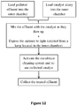
- the present invention further provides methods for treating polluted effluent according to claim 11. Accordingly, the invention provides a method for treatment of a polluted effluent in the system of the invention, said method comprises:
- Fig. 12 schematically summarizes the above described method.
- the invention provides a method for treatment of a polluted effluent in the array of systems of the invention, said method comprises:
- said auxiliary compounds are selected from oxygen, hydrogen peroxide, acid or base for pH adjustment, and oxidants/reducing compounds.
- the concentration of the catalyst(s) and/or organoclay(s) in the outer chamber 10 , of each system is essentially constant throughout the entire chamber.
- the main purpose of the preliminary experiment was to screen a series of pollutants, in order to determine in which cases it is possible to improve considerably photodegradation that might occur anyway, when irradiating pollutants with UVC light (254nm) combined with a catalyst. All preliminary experiments were performed with organic pollutants, divided to 5 families: (a) anionic dyes, (b) cationic dyes, (c) pharmaceuticals, (d) phenols and polyphenols, (e) pesticides.
- the preliminary experiments were performed as "batch” experiments, in order to observe the influence of different catalysts by irradiating them with UV light (254 nm) during two hours.
- Initial concentration of each pollutant was prepared in order to obtain a UV-Visible OD of 1.2-1.5, to allow efficient and accurate monitoring of the decrease in concentration of the pollutant.
- Catalysts were added (when added) at 0.2 g/L.
- the UV-VIS spectrum after 2h was measured, and OD at the wavelength of maximum absorption of the pure pollutant was recorded, and the relative reduction from the initial value was evaluated.
- Table 1 concentrates the results: Table 1 pollutant catalyst catalyzed photodegradation photodegradation without catalyst Anionic Dyes Acid Yellow TiO 2 74% 67% Fast Green SHCa-1 96% 70% TiO 2 97% Flourescein SHCa-1 76% 73% Ponceau Red SHCa-1 45% 24% Cationic Dyes Rhodamine B SHCa-1 93% 77% Crystal Violet TiO 2 80% 62% Acriflavine TiO 2 98% 95% Phenols Caffeine TiO 2 93% 19% Picric Acid TiO 2 98% 10% Three-chloro- phenol (TCP) SHCa-1 95% 50% Li-hectorite 94% SWy-2 93% TiO 2 96% Pharmaceuticals Acetaminophen TiO 2 99% 42% Chloramphenicol TiO 2 72% 48% Tetracycline Cu SWy-2 94% 70% Pesticides Methyl Viologen ("Paraquat” ®) TiO 2 93% 42% Ethoxyquin ("Decco
- v the reaction rate (the rate in which the concentration C of the pollutant changes with time)
- k the kinetics constant
- a the order of the process- that is empirically found, and is related to the mechanism in which the process occurs (White, 2003).
- the reaction rate is not a function of the reactant concentration.
- a 1 st order reaction means that the reaction proceeds at a rate that depends linearly on the concentration of the reactant (this means that the rate at which a reactant is consumed is proportional to its concentration at that time).
- Equations presented hereby are generally referred as "pseudo-order equations", since they consider only the concentration of one component (in this case, the pollutant). This assumption is logical when either the other components don't influence the process, or their concentration is so large that no measurable changes can be observed. In the present case, the products don't influence the photodegradation process.
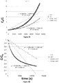
- Fig. 3 shows concentration of the dye fast green as a function of time, when UV light is applied without catalyst ("non") or with TiO 2 ("cat"). Linear regressions are shown also in the figure. The concentration of the dye was monitored in a flowing cuvette in a diode array UV-visible spectrophotometer. It can be seen that there is substantial photodegradation of the dye without catalyst, however the TiO 2 increases the rate of degradation.
- Figure 3A-C presents the fit to a 0 th , 1 st and 2 nd order kinetics, respectively.
- Figs 3A and 3C show that there is no good fit for the 0 th and 2 nd order process, with the linear line, which might mean that both catalyzed and non-catalyzed processes follow a pseudo 1 st order path.
- Fig. 3B shows that there is a very good fit for both catalyzed and uncatalyzed reactions (thus with and without the catalyst TiO 2 ) when fitted to a 1 st order reaction.
- TiO 2 markedly increases the reaction rate (evident by the slope of the lines) by almost 50% (2.14x10 -4 s -1 compared to 1.44x10 -4 s -1 ).
- the half-live time of the reactant can be evaluated accordingly to be about 4170 and 2960 sec. for the non-catalyzed and the catalyzed processes, respectively.
- fast green photodegradation is a 1 st order process, that is considerably accelerated by the catalyzed reaction in the system of the invention.
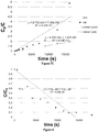
- Fig. 4A shows that non-catalyzed picric acid degrades with UV radiation following a 0 th order pathway.
- the addition of TiO 2 yields results that cannot be adapted to neither a 0 th nor a 1 st order reaction.
- Fig. 4C shows that the fit of the catalyzed photodegradation to a 2 nd order reaction is very good.
- the half-live time of picric acid is evaluated according to the suitable order for each reaction to be about 10700 and 3670 sec. for the non-catalyzed and catalyzed processes, respectively.
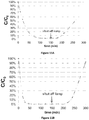
- Figs. 5A (0 th order), 5B (1 st order) and 5C (2 nd order) show degradation of acetaminophen (paracetamol) with or without the catalyst TiO 2 ("cat” or “non”, respectively), and with a catalyst but without the addition of air (“no air”).
- the reaction changes course. Dissolved oxygen measurements show that these course changes are due to the lack of oxygen needed for the catalysis reaction.
- the squares-lines represent a reaction with the catalyst while bubbling air into the liquid to replenish the oxygen and avoid anoxic conditions.
- acetaminophen degradation (without a catalyst) with UV radiation fits quit well to a 0 th order process ( Figs. 5A ), but a better fit can be seen for the 1 st order reaction ( Fig. 5B ) with a half-life time of about 28,000 sec.
- Figs. 5A and 5B addition of TiO 2 yields results that cannot be adapted to neither a 0 th nor a 1 st order reaction.
- Fig. 5C shows that the fit of the catalyzed photodegradation to a 2 nd order reaction is very good, with an acetaminophen half-life time of about 6,280 sec.
- Figs. 7A-C (0 th order, 1 st order and 2 nd order, respectively) show photodegradation of the antibiotic chloramphenicol with or without the catalyst TiO 2 ("cat" or "non", respectively)
- Cat or "non"
- Non-catalyzed results fit quite well to a 0 th order reaction with a half-life time of about 15800 sec. Good fit can be also be seen for the 1 st and even for the 2 nd order processes ( Figs. 7B and 7C ).
- 0 th order fit should be preferred for the non-catalyzed process.
- Fig. 8 shows LCMS measurements of the photodegradation of acetaminophen catalyzed by TiO 2 .
- the measurements clearly confirm the UV-visible measurements shown in Figs. 5A-C and 6 .
- Acetaminophen half-life time in this case (as evaluated by a 1 st order linearization) is 4,130 sec, slightly lower compared to the 6,300 sec. that was calculated in the UV-visible experiment. The difference might be ascribed to different experiment conditions, but nevertheless the values are very close and are of the same order of magnitude.
- Fig. 9 shows LCMS measurements of picric acid photodegradation in the presence of the catalyst TiO 2 adapted to a 2 nd order reaction: after 7 h (c.a. 25,000, results not shown in the figure), less than 2% of the added picric acid (0.4 mM) remained.
- Fig 10 shows TOC measurements of the photodegradation of chloramphenicol from an initial concentration of 25 ppm with or without the catalyst TiO 2 ("cat" or “non", respectively). It can be seen that while both catalyzed and non-catalyzed values decrease constantly, when catalyzed, the concentration of chloramphenicol after 450 min. goes below the LOD of the measuring instrument. Similar results were obtained for TOC measurements of picric acid photodegradation (not shown). As for acetaminophen, TOC measurements indicate only a 60% mineralization (not shown).
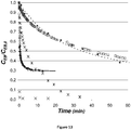
- Figs. 11A-C the behavior for all tested pollutants is as expected. At the tested pollutant concentration (2 ppm) and the flow rate (20 ml/min) applied in the experiments, full degradation of acetaminophen ( Fig. 11A ), picric acid ( Fig. 11B ) and chloramphenicol ( Fig. 11C ) is achieved after 90, 30 and 40 min., respectively.
- CEC Cation Exchange Capacity
- Crystal violet was obtained from Fluka Chemica (Fluka Chemie AG, Buchs, Switzerland).
- Erythrosine-B (EB) was purchased from Spectrum (Gardena, CA, USA).
- 2,4,5-trichlorophenol (TCP) was obtained from Aldrich (Germany).
- High-quality C4386 activated carbon was obtained from Sigma (Germany). All materials were used without further treatment or purification.
- An organoclay with CV up to 100% of the CEC (denoted as M100) was prepared by adding 1 g dry clay to 200 ml of distilled water, and stirring it for several minutes, until homogenous suspension was observed. CV powder was added slowly, and stirring continued for 2 h. The amount of CV adsorbed was calculated by sampling and filtering the suspension and measuring the remaining dye in the supernatant by UV-visible spectroscopy using an HP 8452A diode array spectrophotometer, at 588 nm. Almost no dye remained in solution, indicating complete adsorption (0.8 mol CV per kilogram crude clay).
- Fig. 13 shows changes of the ratio between measured EB concentration as a function of time (C EB ) and its initial concentration (C EB,0 ).
- C EB measured EB concentration
- C EB,0 initial concentration
- the calculated values for q e for both sorbents were relatively similar: 15.6 and 17.2 g kg -1 for M100 and AC, respectively.
- the rates of sorption (k) were calculated as from Fig. 14 , where 2.45 ⁇ 10 -2 kg g -1 min -1 is for AC, with complete adsorption achieved only after more than 20 min; whereas for M100, equilibrium and almost complete removal are observed in less than 0.5 min.
- k M100 ⁇ 8.2 kg g -1 min -1 , thus at least two orders of magnitude larger than the sorption rate to AC at the same conditions.
- organoclay particles based on montmorillonite saturated with CV presented sorption rates of EB and a phenolic pollutant at least two orders of magnitude faster than AC.
- sorption kinetics is one of the limiting factors in the removal of organic pollutants from water
- a fast sorbent such as the organoclay compound might have wide environmental uses.
- the clay mineral used was commercial Wyoming Nabentonite (SWy-2) obtained from the Source Clays Repository of The Clay Minerals Society (Columbia, MO).
- the CEC of the clay bentonite is reported as 0.8 mole/kg. Yunclillos sepiolite was used for the sequential batch experiments, and was provided by TOLSA S.A.
- Lyrad powdered and Lyrad HL-820 were purchased from Lyrad chemicals L.T.D. (Israel), Char Coal - C-4386 was purchased from Sigma (Germany) and Chemviron 9107 was obtained from Chemviron carbon (USA). All materials were used without further treatment or purification.
- TPP tetraphenylphosphonium cations
- Organoclays were prepared by the following procedure: 1 g of SWy-2 clay was added gradually to 200 ml of stirred distilled water, until a homogenous dispersion was achieved. Appropriate amounts of CV or TPP powder were added gradually while stirring and the complex was allowed to reach equilibrium. The organoclay dispersion was used without drying, since preliminary experiments showed that the use of dried organoclay yields slower adsorption kinetics. The amount of organic cation adsorbed was evaluated by measuring CV or TPP concentrations at the supernatant. In all cases more than 99.5% of the added cations were adsorbed.
- the adsorbents are denoted as CV-organoclay or TPP-organoclay for montmorillonite with CV adsorbed amount 100% of the CEC, or with TPP 70% of the CEC, respectively.
- CV-organoclay or TPP-organoclay for montmorillonite with CV adsorbed amount 100% of the CEC, or with TPP 70% of the CEC, respectively.
- Adsorption isotherms were measured in 10 ml glass tubes with plastic screw caps by adding a continuously stirred organoclay suspension (5 g/L), and the appropriate amount of pollutant.
- the exact amount of organoclay for each adsorption isotherm was adapted to the solubility of the pollutant in case, and kept constant for each pollutant. Distilled water was added to achieve a final volume of 10 ml. Preliminary studies showed that equilibrium was reached in less than a minute. Nevertheless, the tubes were agitated on an orbital shaker for 24 h to ensure equilibrium and then centrifuged at 2000 RPM for 30 min.
- the supernatant was measured for the relevant pollutant using a diode-array HP 8452A UV-Visible spectrophotometer.
- the TCP, 2CP, 4NP and phenol were measured in their phenolate form after the pH was raised with NaOH prior to measuring the spectra.
- the effluent was PA 0.1 mM solution, flowing at a volume rate of 1.07 ⁇ 0.03 ml min -1 .
- Concentration of PA was measured at the outflow as described above, and normalized to the initial concentration. Removal of remaining traces of CV was ensured by adding at the bottom of the treated column about 2 cm of sand mixed with crude clay.
- TPP Adsorption of TPP on montmorillonite. Table 2 below shows the amounts of TPP adsorbed, and the electrokinetic charge of the particles as measured by PCD. TPP adsorbs up to approximately 90% of the CEC, and the adsorption neutralizes completely the initial negative charge of the mineral. It should be emphasized that adsorption of CV to the same montmorillonite can reach almost 200% of the CEC (Rytwo et al., 1995) and the charge might reach values of about +0.130 mol c kg -1 . However, when the added amounts of CV were close to the CEC, the charge of the particles was close to neutral.
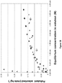
- Fig. 15 presents adsorption isotherms of pollutants on montmorillonite modified with CV adsorbed up to 100% of the CEC.
- the amount of sorbent was varied with each pollutant, according to its solubility.
- Naphthalene, PA and TCP present H-type isotherms, indicating high affinity between adsorbent and adsorbate. Complete adsorption of both pollutants is observed up to 0.15 and 0.35 mol kg -1 PA and TCP, respectively.
- Adsorption of 2CP and 4NP are of Langmuir type, and reach relatively similar amounts. Adsorption of phenol is relatively low, and shows an almost linear isotherm, which insinuates a partitioning mechanism.
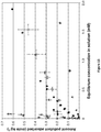
- Fig. 16 presents adsorption isotherm of TCP at an adsorbent content of 0.05%, (0.1% for Lyrad HL820) after 24 h. It should be noticed that the adsorbent content is very low, and this may mislead: for example, by increasing the adsorbent content to 0.5%, all presented adsorbents (except the low quality activated carbon) including CV-organoclay, remove at least 95% of the TCP up to its limit of solubility. On the other hand, Fig.
- Fig. 17 shows the ratio of PA concentration in the outflow of the columns to its initial concentration (0.1 mM), as a function of the number of column pore volumes of polluted effluent that has passed through each column.
- the organoclay-column shows complete removal up to 26 pore volumes, then decreasing performance. It should be emphasized that by lowering the initial pollutant concentration the volumes of completely clean water increases. Similar results were obtained for other pollutants, and with other CV organoclays. Increasing the degree of saturation of CV above 100% of the CEC yields somehow better filtering results, but might leave traces of CV at the solution. For that purpose, crude clay/sand mixture is added at the bottom of the column, and it removes traces of CV very efficiently.
- CV-organoclays shows impressive capacity and very fast adsorption, there are several withdraws which set the path for looking after other organic cations, which may yield similar efficient results.
- the main withdraw of CV-organoclays is that crystal violet is considered harmful and toxic.
- the target is to prepare a filter that might treat industrial effluents in order to allow its release to the environment, the use of CV at the filtering device might look as an oxymoron. It should be emphasized that such problem is mainly subjective since CV adsorption to montmorillonite up to 100% of the CEC is completely irreversible, and no release of CV is adsorbed at those amounts, even while competing with other dyes which have a large affinity to montmorillonite like methylene blue or acriflavin.
- the TPP-organoclay is less effective for most pollutants ( Fig. 18 ).
- 4NP and 2CP show an L-type isotherm, and even TCP which has a large affinity to CV-organoclay (H-type isotherm), presents an L-type isotherm, with incomplete removal.
- TPP organoclay removes very efficiently naphthalene, with a high affinity isotherm, and leads to complete removal up to 0.25 mol kg -1 . The remaining naphthalene concentrations in the TPP-organoclay suspensions are lower than those observed for the CV-organoclay suspensions.
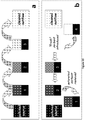
- Fig. 19 shows a scheme of such purification plant, based on suspensions of organoclay.
- Fig. 19a shows the basic purification cycle. The polluted effluent is introduced into the first batch vessel, stirred and left to react for a few minutes, and the solids flocculate. The supernatant is drained and introduced to the second vessel, while the first vessel is filled again with polluted solution. After the third vessel the first cycle is ended, as clean effluent with no pollutant is obtained.
- the process can go on while monitoring the pollutant concentration after the third vessel.
- concentration of the pollutant reaches a limiting value, ( Fig. 19b ) the highly polluted first vessel is removed, the second vessel is moved to position 1, the third to position 2, and a new vessel containing unpolluted adsorbent is added at position 3.
- each batch vessel contained a total volume of 10 ml with 5 g L -1 CV-clay. Due to the sensitivity to traces left of crystal violet 0.1 g L -1 crude sepiolite was added, which might adsorb very large amounts of crystal violet by interactions with charged and neutral sites.
- the polluted effluent contained very high concentration of TCP (1000 mM). Table 3 below shows the concentration of the effluent after the third vessel. After the 9 th cycle, when the pollutant concentration reached more than 3 ⁇ M, a new vessel was introduced, as described above ( Fig. 19b ). It should be emphasized that the concentration was even then almost three orders of magnitude lower than the initial polluted effluent.
- the "sequential batch” technique appears to have higher potential of adsorption, even though it needs a more complicated technical setup and constant monitoring.
- such purification device based on a fast adsorbing organoclay as active component will be able to yield large amounts of pollutant removed over a relatively smaller amount of adsorbent.
Landscapes
- Chemical & Material Sciences (AREA)
- Organic Chemistry (AREA)
- Engineering & Computer Science (AREA)
- Life Sciences & Earth Sciences (AREA)
- Environmental & Geological Engineering (AREA)
- Hydrology & Water Resources (AREA)
- Water Supply & Treatment (AREA)
- Chemical Kinetics & Catalysis (AREA)
- Inorganic Chemistry (AREA)
- Analytical Chemistry (AREA)
- Toxicology (AREA)
- Health & Medical Sciences (AREA)
- Materials Engineering (AREA)
- Dispersion Chemistry (AREA)
- Geochemistry & Mineralogy (AREA)
- Treatment Of Water By Oxidation Or Reduction (AREA)
- Catalysts (AREA)
- Physical Water Treatments (AREA)
Claims (13)
- Système de traitement d'effluents pollués, ledit système comprenant :a. une chambre externe (10) destinée à traiter les effluents pollués en mélange avec une boue de purification comprenant des particules d'un ou plusieurs catalyseur(s) et/ou des argiles organiques, ou un mélange de celles-ci, ladite chambre externe (10) comprenant :(i) une unité de mélange composée d'un moteur (11) et d'un moyen de mélange (16), afin de mélanger les effluents pollués et la boue de purification de façon à empêcher lesdites particules de couler sans provoquer de turbulence ;(ii) une membrane (22) située au niveau de la partie supérieure de la chambre externe (10), et à travers laquelle les effluents traités passent, tout en empêchant lesdites particules d'un ou plusieurs catalyseur(s) et/ou les argiles organiques de sortir de la chambre externe (10) avec les effluents traités ;(iii) au moins une admission (18, 20) située au niveau de la partie inférieure de la chambre externe (10), depuis laquelle les effluents pollués et/ou la boue de purification pénètrent dans la chambre externe (10) ;(iv) une ou des admission(s) optionnelle(s) (21) destinée(s) à ajouter des composés auxiliaires dans la chambre externe ;(v) un système de nettoyage de membrane (14) destiné à éliminer et à collecter lesdites particules d'un ou plusieurs catalyseur(s) et/ou les argiles organiques accumulées sur la membrane (22), et à réintroduire lesdites particules dans la partie inférieure de la chambre externe (10), ledit système de nettoyage de membrane (14) comprenant :(1) un moyen d'aspiration (24) destiné à éliminer les particules accumulées sur la membrane (22) en créant un vide qui aspire les particules de catalyseur et/ou les argiles organiques qui s'accumulent sur la membrane ;(2) un moteur destiné à faire tourner ledit moyen d'aspiration (24) à travers ladite membrane ; et(3) un moyen de collecte (23) destiné à collecter les particules éliminées, qui est relié de manière fluide (a) audit moyen d'aspiration (24) ; et (b) à un tube destiné à transférer les particules collectées de catalyseur(s) et/ou les argiles organiques vers la partie inférieure de la chambre externe (10) par le biais d'une admission de boue de purification ou d'une admission secondaire ;(vi) une ouverture destinée à contenir des capteurs, et des capteurs destinés à surveiller les performances du système ; et(vii) une évacuation (13) au niveau de la partie supérieure de la chambre externe (10), depuis laquelle les effluents traités sortent de la chambre externe (10) ;b. un filtre ; etc. un système de commande informatisé destiné à contrôler le débit des effluents et de la boue de purification, et à surveiller le niveau de polluant(s) dans les effluents traités.
- Système selon la revendication 1, comprenant en outre, à l'intérieur de ladite chambre externe (10), une chambre transparente interne conçue pour contenir une lampe (15), pour le traitement des effluents pollués par photocatalyse, ledit système comprenant :a. une chambre externe (10) destinée à traiter les effluents pollués en mélange avec une boue de purification qui comprend des particules d'un ou plusieurs catalyseur(s), ladite chambre externe (10) comprenant :(i) une unité de mélange composée d'un moteur (11) et d'un moyen de mélange (16), afin de mélanger les effluents pollués et la boue de purification afin d'empêcher lesdites particules de couler sans provoquer de turbulence ;(ii) une membrane (22) située au niveau de la partie supérieure de la chambre externe (10) et à travers laquelle les effluents traités passent, tout en empêchant lesdites particules de catalyseur de sortir de la chambre externe (10) avec les effluents traités ;(iii) au moins une admission (18, 20) située au niveau de la partie inférieure de la chambre, depuis laquelle les effluents pollués et/ou la boue de catalyseur pénètrent dans la chambre externe (10) ;(iv) au moins une admission (21) située au niveau de la partie inférieure de la chambre externe (10), et à laquelle des composés auxiliaires et/ou des pompes à oxygène (17, 19) peuvent être relié(es) ;(v) un système de nettoyage de membrane (14) destiné à éliminer et à collecter lesdites particules d'un ou plusieurs catalyseur(s) et/ou les argiles organiques accumulées sur la membrane (22), et à réintroduire lesdites particules dans la partie inférieure de la chambre externe (10), ledit système de nettoyage de membrane (14) comprenant :(1) un moyen d'aspiration (24) destiné à éliminer les particules accumulées sur la membrane (22) en créant un vide qui aspire les particules de catalyseur et/ou les argiles organiques qui s'accumulent sur la membrane ;(2) un moteur destiné à faire tourner ledit moyen d'aspiration (24) à travers ladite membrane ; et(3) un moyen de collecte (23) destiné à collecter les particules de catalyseur éliminées, qui est relié de manière fluide (a) audit moyen d'aspiration (24) ; et (b) à un tube destiné à transférer les particules collectées de catalyseur(s) et/ou les argiles organiques vers la partie inférieure de la chambre externe (10) par le biais d'une admission de boue de purification ou d'une admission secondaire ;(vi) une ouverture destinée à contenir des capteurs, et des capteurs destinés à surveiller les performances du système ; et(vii) une évacuation (13) au niveau de la partie supérieure de la chambre externe (10), depuis laquelle les effluents traités sortent de la chambre externe (10) ;b. une chambre interne transparente destinée à contenir une lampe (15), située à l'intérieur de la chambre externe (10) ;c. une lampe à UV (15) ;d. un filtre ; ete. un système de commande informatisé destiné à contrôler le débit des effluents et de la boue de catalyseur(s), et à surveiller le niveau de polluant(s) dans les effluents traités.
- Système selon la revendication 1 ou 2, dans lequel les effluents traités qui sortent par l'évacuation (13) au niveau de la partie supérieure de la chambre externe (10) sont renvoyés vers la au moins une admission (18, 20) au niveau de la partie inférieure de la chambre externe (10) en vue d'un traitement supplémentaire.
- Système selon la revendication 1 ou 2, dans lequel le moteur (11) de l'unité de mélange est également le moteur du système de nettoyage de membrane (14).
- Système selon la revendication 1 ou 2, dans lequel le système de nettoyage de membrane (14) comprend en outre une brosse ou un balai pivotant(e) relié(e) au moyen d'aspiration (24) afin d'éliminer physiquement les particules de catalyseurs et/ou les argiles organiques accumulées sur la membrane.
- Système selon la revendication 5, dans lequel ladite brosse ou ledit balai est creuse/creux et constitue la terminaison du moyen d'aspiration (24).
- Système selon la revendication 1 ou 2, dans lequel lesdits capteurs mesurent un ou plusieurs de : le pH, la température, et la conductivité électrique des effluents ; la concentration en catalyseur(s) et/ou argiles organiques ; la concentration en polluants ; l'intensité lumineuse ; le potentiel de redox ; la concentration en O2 et CO2.
- Système selon la revendication 1 ou 2, dans lequel ledit système de commande informatisé contrôle le débit des effluents pollués qui pénètrent dans le système, la quantité de boue de purification qui pénètre dans le système, la vitesse de mélange, la quantité d'air/d'oxygène soufflée dans la chambre externe (10) si nécessaire, l'ajout de composé(s) auxiliaire(s) si nécessaire, et la longueur d'onde et l'intensité de la lumière le cas échéant.
- Ensemble de systèmes selon l'une quelconque des revendications 1 à 8, pour le traitement d'effluents pollués, ledit ensemble de systèmes comprenant au moins deux systèmes reliés en tandem via un tube relié de manière fluide (a) au moyen de collecte (23) dans le système de nettoyage de membrane (14) d'un premier système ; et (b) au moins une admission (18, 20) au niveau de la partie inférieure de la chambre externe (10) d'un second système.
- Ensemble de systèmes selon la revendication 9, dans lequel chaque système comprend un catalyseur et/ou une argile organique différent(e) et/ou une lampe (15) et/ou des composés auxiliaires.
- Procédé de traitement d'effluents pollués dans le système selon l'une quelconque des revendications 1 à 8, comprenant :a) le filtrage des effluents afin d'éliminer les particules de grande taille ;b) le pompage des effluents pollués filtrés vers la partie inférieure de la chambre externe (10) ;c) le pompage de la boue de purification qui comprend des particules d'un(e) ou plusieurs catalyseur(s) et/ou argile(s) organique(s) vers la partie inférieure de la chambre externe (10) ;d) le mélange des effluents pollués et de la boue de purification dans la chambre externe (10) sans provoquer de turbulence ;e) le cas échéant, l'allumage de la lumière et l'exposition du mélange boue de purification/effluents à la lumière ;f) la surveillance de la concentration en polluant(s) dans les effluents dans la chambre externe (10) et dans les effluents traités qui sortent de la chambre externe (10) ;g) le pompage des composés auxiliaires et de l'oxygène vers la chambre externe (10) si nécessaire ;h) le nettoyage de la membrane (22) en éliminant de celle-ci les particules de catalyseurs et/ou d'argiles organiques, et leur transfert vers la partie inférieure de la chambre externe (10) via ledit tube relié de manière fluide audit système de nettoyage de membrane (14) ; eti) l'évacuation des effluents traités qui sortent de la chambre externe (10) vers un système adapté, comme le système d'égouts ou un système d'irrigation, ou le renvoi des effluents traités vers la partie inférieure de la chambre externe (10) en vue d'un traitement supplémentaire.
- Procédé de traitement d'effluents pollués dans l'ensemble de systèmes selon l'une quelconque des revendications 9 à 10, comprenant :a) le filtrage des effluents afin d'éliminer les particules de grande taille ;b) le pompage des effluents pollués filtrés vers la partie inférieure de la première chambre externe (10) ;c) le pompage de la boue de purification qui comprend des particules d'un(e) ou plusieurs catalyseur(s) et/ou argile(s) organique(s) vers la partie inférieure de la première chambre externe (10) ;d) le mélange des effluents pollués et de la boue de purification dans la chambre externe (10) sans provoquer de turbulence ;e) le cas échéant, l'allumage de la lumière et l'exposition du mélange boue de purification/effluents à la lumière ;f) la surveillance de la concentration en polluant(s) dans les effluents dans la chambre externe (10) et dans les effluents traités qui sortent de la chambre externe (10) ;g) le pompage des composés auxiliaires et de l'oxygène vers la chambre externe (10) si nécessaire ;h) le nettoyage de la membrane (22) en éliminant de celle-ci les particules de catalyseurs et/ou d'argiles organiques, et leur transfert vers la partie inférieure de la chambre externe (10) via ledit tube relié de manière fluide audit système de nettoyage de membrane (14) ;i) le transfert des effluents traités vers la chambre externe (10) du système suivant en vue d'un traitement supplémentaire ou d'un traitement différent avec un autre catalyseur et/ou une autre argile organique et/ou une source et une longueur d'onde de lumière différentes ;j) la répétition des étapes (i) si nécessaire et selon le nombre de systèmes de l'ensemble de systèmes ; etk) l'évacuation des effluents traités qui sortent de la chambre externe (10) du dernier système vers un système adapté, comme le système d'égouts ou un système d'irrigation.
- Procédé selon la revendication 11 ou 12, dans lequel la concentration en catalyseur(s) et/ou en argile(s) organique(s) dans la chambre externe (10) est essentiellement constante dans la chambre entière.
Applications Claiming Priority (2)
| Application Number | Priority Date | Filing Date | Title |
|---|---|---|---|
| GBGB1416495.8A GB201416495D0 (en) | 2014-09-18 | 2014-09-18 | A system for treatment of polluted effluents by photocatalysis |
| PCT/IL2015/050944 WO2016042558A1 (fr) | 2014-09-18 | 2015-09-17 | Système pour le traitement d'effluents pollués |
Publications (3)
| Publication Number | Publication Date |
|---|---|
| EP3194342A1 EP3194342A1 (fr) | 2017-07-26 |
| EP3194342A4 EP3194342A4 (fr) | 2018-04-11 |
| EP3194342B1 true EP3194342B1 (fr) | 2020-11-04 |
Family
ID=51869105
Family Applications (1)
| Application Number | Title | Priority Date | Filing Date |
|---|---|---|---|
| EP15842324.4A Active EP3194342B1 (fr) | 2014-09-18 | 2015-09-17 | Système pour le traitement d'effluents pollués |
Country Status (6)
| Country | Link |
|---|---|
| US (1) | US11034599B2 (fr) |
| EP (1) | EP3194342B1 (fr) |
| ES (1) | ES2844698T3 (fr) |
| GB (1) | GB201416495D0 (fr) |
| IL (2) | IL251146B (fr) |
| WO (1) | WO2016042558A1 (fr) |
Families Citing this family (8)
| Publication number | Priority date | Publication date | Assignee | Title |
|---|---|---|---|---|
| CN109534477B (zh) * | 2018-11-30 | 2021-11-19 | 华南师范大学 | 一种林可霉素的降解方法 |
| CN109279677A (zh) * | 2018-12-01 | 2019-01-29 | 浙江海洋大学 | 一种脱除水中新诺明光催化装置及方法 |
| CN110394183A (zh) * | 2019-07-29 | 2019-11-01 | 常州大学 | 一种ATP/Zn0.5Cd0.5S复合可见光催化剂的制备方法 |
| CN110759418A (zh) * | 2019-11-05 | 2020-02-07 | 佛山市金净创环保技术有限公司 | 一种光催化降解搅拌器 |
| CN111333213B (zh) * | 2020-02-27 | 2021-05-14 | 华南理工大学 | 一种硅酸钙板生产过程中蒸压釜蒸汽冷凝水的除臭方法 |
| CN111257541B (zh) * | 2020-03-12 | 2022-07-01 | 湖南科技大学 | 一种连续测定土体状态等温吸附曲线的方法 |
| CN113753986B (zh) * | 2021-10-01 | 2023-03-14 | 太原工业学院 | 基于水环境污染物便捷取放的光催化降解装置 |
| CN116199354B (zh) * | 2021-11-29 | 2025-01-07 | 中国科学院宁波材料技术与工程研究所 | 一种含2,5-呋喃二甲酸废水的处理方法 |
Family Cites Families (15)
| Publication number | Priority date | Publication date | Assignee | Title |
|---|---|---|---|---|
| US3256995A (en) * | 1963-07-05 | 1966-06-21 | Zurn Ind Inc | Automatic strainer |
| US5462674A (en) * | 1994-03-03 | 1995-10-31 | Purific Environmental Technologies, Inc. | Method and system for photocatalytic decontamination |
| US6117337A (en) * | 1997-01-31 | 2000-09-12 | Lynntech, Inc. | Enhanced photocatalytic oxidation of organics using a porous titanium dioxide membrane |
| JP3858734B2 (ja) | 2002-03-13 | 2006-12-20 | 石川島播磨重工業株式会社 | 水処理装置 |
| FR2861718B1 (fr) * | 2003-10-30 | 2006-03-03 | Otv Sa | Installation et procede d'epuration d'un effluent aqueux par oxydation et par filtration membranaire. |
| US7547418B2 (en) * | 2004-01-23 | 2009-06-16 | Gm Global Technology Operations, Inc. | Fluidized-bed reactor system |
| US7097046B2 (en) | 2004-03-03 | 2006-08-29 | Gerry Calabrese | Automatically cleaning filter assembly for a liquid-carrying loop |
| US7326330B2 (en) * | 2004-06-10 | 2008-02-05 | Miox Corporation | Method and apparatus for scale and biofilm control |
| GB0501688D0 (en) | 2005-01-27 | 2005-03-02 | Univ Cranfield | Method and apparatus |
| US7837952B2 (en) * | 2007-03-09 | 2010-11-23 | Butters Brian E | System and method for removal of hydrogen peroxide from a contaminated media |
| GB201018555D0 (en) | 2010-11-03 | 2010-12-15 | Albagaia Ltd | Fluid treatment apparatus |
| FR2990935B1 (fr) | 2012-05-25 | 2014-09-19 | Processium | Procede et dispositif de traitement d'epuration d'effluents liquides, en particulier aqueux par photocatalyse |
| US20150090660A1 (en) * | 2013-09-30 | 2015-04-02 | University of Alaska Anchorage | Light-Assisted Membrane Treatment and Cleaning |
| US9751785B2 (en) * | 2013-10-08 | 2017-09-05 | Arizona Board Of Regents For And On Behalf Of Arizona State University | Photocatalytic reduction of oxo-anions |
| CN103557559B (zh) | 2013-11-05 | 2016-01-27 | 北京理工大学 | 一种高效空气净化器 |
-
2014
- 2014-09-18 GB GBGB1416495.8A patent/GB201416495D0/en not_active Ceased
-
2015
- 2015-09-17 ES ES15842324T patent/ES2844698T3/es active Active
- 2015-09-17 EP EP15842324.4A patent/EP3194342B1/fr active Active
- 2015-09-17 WO PCT/IL2015/050944 patent/WO2016042558A1/fr not_active Ceased
- 2015-09-17 US US15/512,516 patent/US11034599B2/en not_active Expired - Fee Related
-
2017
- 2017-03-14 IL IL251146A patent/IL251146B/en unknown
-
2021
- 2021-06-16 IL IL284089A patent/IL284089B/en unknown
Non-Patent Citations (1)
| Title |
|---|
| None * |
Also Published As
| Publication number | Publication date |
|---|---|
| US11034599B2 (en) | 2021-06-15 |
| EP3194342A1 (fr) | 2017-07-26 |
| ES2844698T3 (es) | 2021-07-22 |
| EP3194342A4 (fr) | 2018-04-11 |
| IL284089A (en) | 2021-07-29 |
| US20170297933A1 (en) | 2017-10-19 |
| WO2016042558A1 (fr) | 2016-03-24 |
| IL251146B (en) | 2021-07-29 |
| IL284089B (en) | 2021-10-31 |
| IL251146A0 (en) | 2017-04-30 |
| GB201416495D0 (en) | 2014-11-05 |
Similar Documents
| Publication | Publication Date | Title |
|---|---|---|
| EP3194342B1 (fr) | Système pour le traitement d'effluents pollués | |
| Giwa et al. | Solar photocatalytic degradation of reactive yellow 81 and reactive violet 1 in aqueous solution containing semiconductor oxides | |
| Dey et al. | Solar assisted photocatalytic degradation of reactive azo dyes in presence of anatase titanium dioxide | |
| Laoufi et al. | The degradation of phenol in water solution by TiO2 photocatalysis in a helical reactor | |
| Kim et al. | Adsorption and photocatalysis kinetics of herbicide onto titanium oxide and powdered activated carbon | |
| Damodar et al. | Performance of an integrated membrane photocatalytic reactor for the removal of Reactive Black 5 | |
| Gomez et al. | In situ generated TiO2 over zeolitic supports as reusable photocatalysts for the degradation of dichlorvos | |
| Salari | Facile synthesis of new Z-scheme Bi2WO6/Bi2MoO6 p–n junction photocatalysts with high photocatalytic activity: Structure, kinetics and mechanism approach | |
| Salavati et al. | Preparation and characterization of polyphosphotungstate/ZrO2 nanocomposite and their sonocatalytic and photocatalytic activity under UV light illumination | |
| Malakootian et al. | Preparation and characterization of TiO2 incorporated 13X molecular sieves for photocatalytic removal of acetaminophen from aqueous solutions | |
| Basha et al. | Studies on the adsorption and kinetics of photodegradation of pharmaceutical compound, indomethacin using novel photocatalytic adsorbents (IPCAs) | |
| EP2035095A2 (fr) | Procédé pour l'adsorption de contaminants fluides et la régénération de l'adsorbant | |
| Shamsi Kasmaei et al. | Kinetic and thermodynamic studies on the reactivity of hydroxyl radicals in wastewater treatment by advanced oxidation processes | |
| Shah et al. | Pharmaceutical residues: new emerging contaminants and their mitigation by nano-photocatalysis | |
| Laoufi et al. | Removal of a persistent pharmaceutical micropollutant by UV/TiO2 process using an immobilized titanium dioxide catalyst: parametric study | |
| Lin et al. | Enhanced visible light photocatalysis by TiO2–BN enabled electrospinning of nanofibers for pharmaceutical degradation and wastewater treatment | |
| Dhibi et al. | Photocatalytic degradation of paracetamol mediating luminous textile: Intensification of the chemical oxidation | |
| Favier et al. | Advanced oxidation process for the removal of chlorinated phenols in aqueous suspensions | |
| Akgun | Photocatalytic degradation of textile dye CI Basic Yellow 28 wastewater by Degussa P25 based TiO 2 | |
| US20210292206A1 (en) | System for treatment of polluted effluents | |
| Khelifi et al. | Treatment of textile dyeing wastewater using advanced photo-oxidation processes for decolorization and COD reduction | |
| Zazouli et al. | Evaluation of the efficiency of the TiO2/UV nano-photocatalytic process in the removal of humic and fulvic acids from aqueous solutions | |
| Khalik et al. | Evaluation on the molecular structure of azo dye in photocatalytic mineralization under solar light irradiation | |
| Sescu et al. | Studies regarding photocatalytic degradation of two different organic compounds | |
| Khosravi et al. | Investigation of TiO2 and ZnO nanoparticles coated on raw pumice for efficient removal of Ethidium bromide from aqueous solutions. |
Legal Events
| Date | Code | Title | Description |
|---|---|---|---|
| STAA | Information on the status of an ep patent application or granted ep patent |
Free format text: STATUS: THE INTERNATIONAL PUBLICATION HAS BEEN MADE |
|
| PUAI | Public reference made under article 153(3) epc to a published international application that has entered the european phase |
Free format text: ORIGINAL CODE: 0009012 |
|
| STAA | Information on the status of an ep patent application or granted ep patent |
Free format text: STATUS: REQUEST FOR EXAMINATION WAS MADE |
|
| 17P | Request for examination filed |
Effective date: 20170414 |
|
| AK | Designated contracting states |
Kind code of ref document: A1 Designated state(s): AL AT BE BG CH CY CZ DE DK EE ES FI FR GB GR HR HU IE IS IT LI LT LU LV MC MK MT NL NO PL PT RO RS SE SI SK SM TR |
|
| AX | Request for extension of the european patent |
Extension state: BA ME |
|
| DAV | Request for validation of the european patent (deleted) | ||
| DAX | Request for extension of the european patent (deleted) | ||
| A4 | Supplementary search report drawn up and despatched |
Effective date: 20180314 |
|
| RIC1 | Information provided on ipc code assigned before grant |
Ipc: C02F 101/30 20060101ALN20180308BHEP Ipc: C02F 103/34 20060101ALN20180308BHEP Ipc: C02F 1/72 20060101ALI20180308BHEP Ipc: C02F 9/12 20060101AFI20180308BHEP Ipc: C02F 1/44 20060101ALI20180308BHEP Ipc: B01D 63/08 20060101ALN20180308BHEP Ipc: B01J 21/06 20060101ALN20180308BHEP Ipc: B01D 65/02 20060101ALI20180308BHEP Ipc: C02F 101/34 20060101ALN20180308BHEP Ipc: C02F 1/66 20060101ALN20180308BHEP Ipc: B01J 8/10 20060101ALI20180308BHEP Ipc: C02F 1/32 20060101ALI20180308BHEP Ipc: C02F 1/28 20060101ALI20180308BHEP Ipc: B01J 20/12 20060101ALN20180308BHEP Ipc: B01J 20/10 20060101ALN20180308BHEP Ipc: C02F 1/70 20060101ALN20180308BHEP Ipc: B01J 20/20 20060101ALN20180308BHEP Ipc: B01J 35/02 20060101ALI20180308BHEP |
|
| GRAP | Despatch of communication of intention to grant a patent |
Free format text: ORIGINAL CODE: EPIDOSNIGR1 |
|
| STAA | Information on the status of an ep patent application or granted ep patent |
Free format text: STATUS: GRANT OF PATENT IS INTENDED |
|
| RIC1 | Information provided on ipc code assigned before grant |
Ipc: C02F 9/12 20060101AFI20200402BHEP Ipc: C02F 1/44 20060101ALI20200402BHEP Ipc: B01J 8/10 20060101ALI20200402BHEP Ipc: C02F 1/66 20060101ALN20200402BHEP Ipc: B01J 35/02 20060101ALI20200402BHEP Ipc: C02F 101/30 20060101ALN20200402BHEP Ipc: B01J 21/06 20060101ALN20200402BHEP Ipc: C02F 101/34 20060101ALN20200402BHEP Ipc: C02F 1/28 20060101ALI20200402BHEP Ipc: B01J 20/12 20060101ALN20200402BHEP Ipc: C02F 103/34 20060101ALN20200402BHEP Ipc: C02F 1/70 20060101ALN20200402BHEP Ipc: B01J 20/10 20060101ALN20200402BHEP Ipc: B01D 65/02 20060101ALI20200402BHEP Ipc: B01J 20/20 20060101ALN20200402BHEP Ipc: B01D 63/08 20060101ALN20200402BHEP Ipc: C02F 1/72 20060101ALI20200402BHEP Ipc: C02F 1/32 20060101ALI20200402BHEP |
|
| INTG | Intention to grant announced |
Effective date: 20200421 |
|
| GRAS | Grant fee paid |
Free format text: ORIGINAL CODE: EPIDOSNIGR3 |
|
| GRAA | (expected) grant |
Free format text: ORIGINAL CODE: 0009210 |
|
| STAA | Information on the status of an ep patent application or granted ep patent |
Free format text: STATUS: THE PATENT HAS BEEN GRANTED |
|
| AK | Designated contracting states |
Kind code of ref document: B1 Designated state(s): AL AT BE BG CH CY CZ DE DK EE ES FI FR GB GR HR HU IE IS IT LI LT LU LV MC MK MT NL NO PL PT RO RS SE SI SK SM TR |
|
| REG | Reference to a national code |
Ref country code: GB Ref legal event code: FG4D |
|
| REG | Reference to a national code |
Ref country code: CH Ref legal event code: EP |
|
| REG | Reference to a national code |
Ref country code: AT Ref legal event code: REF Ref document number: 1330612 Country of ref document: AT Kind code of ref document: T Effective date: 20201115 |
|
| REG | Reference to a national code |
Ref country code: DE Ref legal event code: R096 Ref document number: 602015061642 Country of ref document: DE |
|
| REG | Reference to a national code |
Ref country code: IE Ref legal event code: FG4D |
|
| REG | Reference to a national code |
Ref country code: CH Ref legal event code: NV Representative=s name: DENNEMEYER AG, CH |
|
| REG | Reference to a national code |
Ref country code: NL Ref legal event code: MP Effective date: 20201104 |
|
| REG | Reference to a national code |
Ref country code: AT Ref legal event code: MK05 Ref document number: 1330612 Country of ref document: AT Kind code of ref document: T Effective date: 20201104 |
|
| PG25 | Lapsed in a contracting state [announced via postgrant information from national office to epo] |
Ref country code: GR Free format text: LAPSE BECAUSE OF FAILURE TO SUBMIT A TRANSLATION OF THE DESCRIPTION OR TO PAY THE FEE WITHIN THE PRESCRIBED TIME-LIMIT Effective date: 20210205 Ref country code: RS Free format text: LAPSE BECAUSE OF FAILURE TO SUBMIT A TRANSLATION OF THE DESCRIPTION OR TO PAY THE FEE WITHIN THE PRESCRIBED TIME-LIMIT Effective date: 20201104 Ref country code: PT Free format text: LAPSE BECAUSE OF FAILURE TO SUBMIT A TRANSLATION OF THE DESCRIPTION OR TO PAY THE FEE WITHIN THE PRESCRIBED TIME-LIMIT Effective date: 20210304 Ref country code: FI Free format text: LAPSE BECAUSE OF FAILURE TO SUBMIT A TRANSLATION OF THE DESCRIPTION OR TO PAY THE FEE WITHIN THE PRESCRIBED TIME-LIMIT Effective date: 20201104 Ref country code: NO Free format text: LAPSE BECAUSE OF FAILURE TO SUBMIT A TRANSLATION OF THE DESCRIPTION OR TO PAY THE FEE WITHIN THE PRESCRIBED TIME-LIMIT Effective date: 20210204 |
|
| PG25 | Lapsed in a contracting state [announced via postgrant information from national office to epo] |
Ref country code: SE Free format text: LAPSE BECAUSE OF FAILURE TO SUBMIT A TRANSLATION OF THE DESCRIPTION OR TO PAY THE FEE WITHIN THE PRESCRIBED TIME-LIMIT Effective date: 20201104 Ref country code: IS Free format text: LAPSE BECAUSE OF FAILURE TO SUBMIT A TRANSLATION OF THE DESCRIPTION OR TO PAY THE FEE WITHIN THE PRESCRIBED TIME-LIMIT Effective date: 20210304 Ref country code: LV Free format text: LAPSE BECAUSE OF FAILURE TO SUBMIT A TRANSLATION OF THE DESCRIPTION OR TO PAY THE FEE WITHIN THE PRESCRIBED TIME-LIMIT Effective date: 20201104 Ref country code: PL Free format text: LAPSE BECAUSE OF FAILURE TO SUBMIT A TRANSLATION OF THE DESCRIPTION OR TO PAY THE FEE WITHIN THE PRESCRIBED TIME-LIMIT Effective date: 20201104 Ref country code: BG Free format text: LAPSE BECAUSE OF FAILURE TO SUBMIT A TRANSLATION OF THE DESCRIPTION OR TO PAY THE FEE WITHIN THE PRESCRIBED TIME-LIMIT Effective date: 20210204 Ref country code: AT Free format text: LAPSE BECAUSE OF FAILURE TO SUBMIT A TRANSLATION OF THE DESCRIPTION OR TO PAY THE FEE WITHIN THE PRESCRIBED TIME-LIMIT Effective date: 20201104 |
|
| REG | Reference to a national code |
Ref country code: LT Ref legal event code: MG9D |
|
| PG25 | Lapsed in a contracting state [announced via postgrant information from national office to epo] |
Ref country code: HR Free format text: LAPSE BECAUSE OF FAILURE TO SUBMIT A TRANSLATION OF THE DESCRIPTION OR TO PAY THE FEE WITHIN THE PRESCRIBED TIME-LIMIT Effective date: 20201104 |
|
| REG | Reference to a national code |
Ref country code: ES Ref legal event code: FG2A Ref document number: 2844698 Country of ref document: ES Kind code of ref document: T3 Effective date: 20210722 |
|
| PG25 | Lapsed in a contracting state [announced via postgrant information from national office to epo] |
Ref country code: RO Free format text: LAPSE BECAUSE OF FAILURE TO SUBMIT A TRANSLATION OF THE DESCRIPTION OR TO PAY THE FEE WITHIN THE PRESCRIBED TIME-LIMIT Effective date: 20201104 Ref country code: SK Free format text: LAPSE BECAUSE OF FAILURE TO SUBMIT A TRANSLATION OF THE DESCRIPTION OR TO PAY THE FEE WITHIN THE PRESCRIBED TIME-LIMIT Effective date: 20201104 Ref country code: LT Free format text: LAPSE BECAUSE OF FAILURE TO SUBMIT A TRANSLATION OF THE DESCRIPTION OR TO PAY THE FEE WITHIN THE PRESCRIBED TIME-LIMIT Effective date: 20201104 Ref country code: SM Free format text: LAPSE BECAUSE OF FAILURE TO SUBMIT A TRANSLATION OF THE DESCRIPTION OR TO PAY THE FEE WITHIN THE PRESCRIBED TIME-LIMIT Effective date: 20201104 Ref country code: CZ Free format text: LAPSE BECAUSE OF FAILURE TO SUBMIT A TRANSLATION OF THE DESCRIPTION OR TO PAY THE FEE WITHIN THE PRESCRIBED TIME-LIMIT Effective date: 20201104 Ref country code: EE Free format text: LAPSE BECAUSE OF FAILURE TO SUBMIT A TRANSLATION OF THE DESCRIPTION OR TO PAY THE FEE WITHIN THE PRESCRIBED TIME-LIMIT Effective date: 20201104 |
|
| REG | Reference to a national code |
Ref country code: DE Ref legal event code: R097 Ref document number: 602015061642 Country of ref document: DE |
|
| PG25 | Lapsed in a contracting state [announced via postgrant information from national office to epo] |
Ref country code: DK Free format text: LAPSE BECAUSE OF FAILURE TO SUBMIT A TRANSLATION OF THE DESCRIPTION OR TO PAY THE FEE WITHIN THE PRESCRIBED TIME-LIMIT Effective date: 20201104 |
|
| PLBE | No opposition filed within time limit |
Free format text: ORIGINAL CODE: 0009261 |
|
| STAA | Information on the status of an ep patent application or granted ep patent |
Free format text: STATUS: NO OPPOSITION FILED WITHIN TIME LIMIT |
|
| 26N | No opposition filed |
Effective date: 20210805 |
|
| PG25 | Lapsed in a contracting state [announced via postgrant information from national office to epo] |
Ref country code: NL Free format text: LAPSE BECAUSE OF FAILURE TO SUBMIT A TRANSLATION OF THE DESCRIPTION OR TO PAY THE FEE WITHIN THE PRESCRIBED TIME-LIMIT Effective date: 20201104 Ref country code: IT Free format text: LAPSE BECAUSE OF FAILURE TO SUBMIT A TRANSLATION OF THE DESCRIPTION OR TO PAY THE FEE WITHIN THE PRESCRIBED TIME-LIMIT Effective date: 20201104 Ref country code: AL Free format text: LAPSE BECAUSE OF FAILURE TO SUBMIT A TRANSLATION OF THE DESCRIPTION OR TO PAY THE FEE WITHIN THE PRESCRIBED TIME-LIMIT Effective date: 20201104 |
|
| PG25 | Lapsed in a contracting state [announced via postgrant information from national office to epo] |
Ref country code: SI Free format text: LAPSE BECAUSE OF FAILURE TO SUBMIT A TRANSLATION OF THE DESCRIPTION OR TO PAY THE FEE WITHIN THE PRESCRIBED TIME-LIMIT Effective date: 20201104 |
|
| REG | Reference to a national code |
Ref country code: BE Ref legal event code: MM Effective date: 20210930 |
|
| PG25 | Lapsed in a contracting state [announced via postgrant information from national office to epo] |
Ref country code: IS Free format text: LAPSE BECAUSE OF FAILURE TO SUBMIT A TRANSLATION OF THE DESCRIPTION OR TO PAY THE FEE WITHIN THE PRESCRIBED TIME-LIMIT Effective date: 20210304 Ref country code: MC Free format text: LAPSE BECAUSE OF FAILURE TO SUBMIT A TRANSLATION OF THE DESCRIPTION OR TO PAY THE FEE WITHIN THE PRESCRIBED TIME-LIMIT Effective date: 20201104 |
|
| PG25 | Lapsed in a contracting state [announced via postgrant information from national office to epo] |
Ref country code: LU Free format text: LAPSE BECAUSE OF NON-PAYMENT OF DUE FEES Effective date: 20210917 Ref country code: IE Free format text: LAPSE BECAUSE OF NON-PAYMENT OF DUE FEES Effective date: 20210917 Ref country code: BE Free format text: LAPSE BECAUSE OF NON-PAYMENT OF DUE FEES Effective date: 20210930 |
|
| REG | Reference to a national code |
Ref country code: DE Ref legal event code: R079 Ref document number: 602015061642 Country of ref document: DE Free format text: PREVIOUS MAIN CLASS: C02F0009120000 Ipc: C02F0009000000 |
|
| PG25 | Lapsed in a contracting state [announced via postgrant information from national office to epo] |
Ref country code: HU Free format text: LAPSE BECAUSE OF FAILURE TO SUBMIT A TRANSLATION OF THE DESCRIPTION OR TO PAY THE FEE WITHIN THE PRESCRIBED TIME-LIMIT; INVALID AB INITIO Effective date: 20150917 |
|
| P01 | Opt-out of the competence of the unified patent court (upc) registered |
Effective date: 20230516 |
|
| PG25 | Lapsed in a contracting state [announced via postgrant information from national office to epo] |
Ref country code: CY Free format text: LAPSE BECAUSE OF FAILURE TO SUBMIT A TRANSLATION OF THE DESCRIPTION OR TO PAY THE FEE WITHIN THE PRESCRIBED TIME-LIMIT Effective date: 20201104 |
|
| PGFP | Annual fee paid to national office [announced via postgrant information from national office to epo] |
Ref country code: GB Payment date: 20230920 Year of fee payment: 9 |
|
| PGFP | Annual fee paid to national office [announced via postgrant information from national office to epo] |
Ref country code: FR Payment date: 20230928 Year of fee payment: 9 Ref country code: DE Payment date: 20230920 Year of fee payment: 9 |
|
| PGFP | Annual fee paid to national office [announced via postgrant information from national office to epo] |
Ref country code: ES Payment date: 20231124 Year of fee payment: 9 |
|
| PGFP | Annual fee paid to national office [announced via postgrant information from national office to epo] |
Ref country code: CH Payment date: 20231001 Year of fee payment: 9 |
|
| PG25 | Lapsed in a contracting state [announced via postgrant information from national office to epo] |
Ref country code: MK Free format text: LAPSE BECAUSE OF FAILURE TO SUBMIT A TRANSLATION OF THE DESCRIPTION OR TO PAY THE FEE WITHIN THE PRESCRIBED TIME-LIMIT Effective date: 20201104 |
|
| PG25 | Lapsed in a contracting state [announced via postgrant information from national office to epo] |
Ref country code: TR Free format text: LAPSE BECAUSE OF FAILURE TO SUBMIT A TRANSLATION OF THE DESCRIPTION OR TO PAY THE FEE WITHIN THE PRESCRIBED TIME-LIMIT Effective date: 20201104 |
|
| PG25 | Lapsed in a contracting state [announced via postgrant information from national office to epo] |
Ref country code: MT Free format text: LAPSE BECAUSE OF FAILURE TO SUBMIT A TRANSLATION OF THE DESCRIPTION OR TO PAY THE FEE WITHIN THE PRESCRIBED TIME-LIMIT Effective date: 20201104 |
|
| REG | Reference to a national code |
Ref country code: DE Ref legal event code: R119 Ref document number: 602015061642 Country of ref document: DE |
|
| REG | Reference to a national code |
Ref country code: CH Ref legal event code: PL |
|
| GBPC | Gb: european patent ceased through non-payment of renewal fee |
Effective date: 20240917 |
|
| PG25 | Lapsed in a contracting state [announced via postgrant information from national office to epo] |
Ref country code: DE Free format text: LAPSE BECAUSE OF NON-PAYMENT OF DUE FEES Effective date: 20250401 |
|
| PG25 | Lapsed in a contracting state [announced via postgrant information from national office to epo] |
Ref country code: GB Free format text: LAPSE BECAUSE OF NON-PAYMENT OF DUE FEES Effective date: 20240917 |
|
| PG25 | Lapsed in a contracting state [announced via postgrant information from national office to epo] |
Ref country code: FR Free format text: LAPSE BECAUSE OF NON-PAYMENT OF DUE FEES Effective date: 20240930 |
|
| PG25 | Lapsed in a contracting state [announced via postgrant information from national office to epo] |
Ref country code: CH Free format text: LAPSE BECAUSE OF NON-PAYMENT OF DUE FEES Effective date: 20240930 |
|
| REG | Reference to a national code |
Ref country code: ES Ref legal event code: FD2A Effective date: 20251031 |
|
| PG25 | Lapsed in a contracting state [announced via postgrant information from national office to epo] |
Ref country code: ES Free format text: LAPSE BECAUSE OF NON-PAYMENT OF DUE FEES Effective date: 20240918 |