EP3194703B1 - Profil de filet résistant à la fatigue ayant une combinaison d'arrondi et de courbe - Google Patents
Profil de filet résistant à la fatigue ayant une combinaison d'arrondi et de courbe Download PDFInfo
- Publication number
- EP3194703B1 EP3194703B1 EP15827231.0A EP15827231A EP3194703B1 EP 3194703 B1 EP3194703 B1 EP 3194703B1 EP 15827231 A EP15827231 A EP 15827231A EP 3194703 B1 EP3194703 B1 EP 3194703B1
- Authority
- EP
- European Patent Office
- Prior art keywords
- radius
- flank
- distal radius
- thread
- medial
- Prior art date
- Legal status (The legal status is an assumption and is not a legal conclusion. Google has not performed a legal analysis and makes no representation as to the accuracy of the status listed.)
- Active
Links
Images

Classifications
-
- E—FIXED CONSTRUCTIONS
- E21—EARTH OR ROCK DRILLING; MINING
- E21B—EARTH OR ROCK DRILLING; OBTAINING OIL, GAS, WATER, SOLUBLE OR MELTABLE MATERIALS OR A SLURRY OF MINERALS FROM WELLS
- E21B17/00—Drilling rods or pipes; Flexible drill strings; Kellies; Drill collars; Sucker rods; Cables; Casings; Tubings
- E21B17/02—Couplings; joints
- E21B17/04—Couplings; joints between rod or the like and bit or between rod and rod or the like
- E21B17/042—Threaded
-
- F—MECHANICAL ENGINEERING; LIGHTING; HEATING; WEAPONS; BLASTING
- F16—ENGINEERING ELEMENTS AND UNITS; GENERAL MEASURES FOR PRODUCING AND MAINTAINING EFFECTIVE FUNCTIONING OF MACHINES OR INSTALLATIONS; THERMAL INSULATION IN GENERAL
- F16L—PIPES; JOINTS OR FITTINGS FOR PIPES; SUPPORTS FOR PIPES, CABLES OR PROTECTIVE TUBING; MEANS FOR THERMAL INSULATION IN GENERAL
- F16L15/00—Screw-threaded joints; Forms of screw-threads for such joints
-
- F—MECHANICAL ENGINEERING; LIGHTING; HEATING; WEAPONS; BLASTING
- F16—ENGINEERING ELEMENTS AND UNITS; GENERAL MEASURES FOR PRODUCING AND MAINTAINING EFFECTIVE FUNCTIONING OF MACHINES OR INSTALLATIONS; THERMAL INSULATION IN GENERAL
- F16L—PIPES; JOINTS OR FITTINGS FOR PIPES; SUPPORTS FOR PIPES, CABLES OR PROTECTIVE TUBING; MEANS FOR THERMAL INSULATION IN GENERAL
- F16L15/00—Screw-threaded joints; Forms of screw-threads for such joints
- F16L15/001—Screw-threaded joints; Forms of screw-threads for such joints with conical threads
-
- F—MECHANICAL ENGINEERING; LIGHTING; HEATING; WEAPONS; BLASTING
- F16—ENGINEERING ELEMENTS AND UNITS; GENERAL MEASURES FOR PRODUCING AND MAINTAINING EFFECTIVE FUNCTIONING OF MACHINES OR INSTALLATIONS; THERMAL INSULATION IN GENERAL
- F16L—PIPES; JOINTS OR FITTINGS FOR PIPES; SUPPORTS FOR PIPES, CABLES OR PROTECTIVE TUBING; MEANS FOR THERMAL INSULATION IN GENERAL
- F16L15/00—Screw-threaded joints; Forms of screw-threads for such joints
- F16L15/06—Screw-threaded joints; Forms of screw-threads for such joints characterised by the shape of the screw-thread
Definitions
- This disclosure relates generally to oilfield downhole tools and more particularly to methods and devices for transferring rotary power to a consumer.
- Threaded connections are a prevalent method to join two or more members such as pipe sections.
- a string of pipe sections joined by threaded connections may be rotated in a well bore.
- a drill string may be rotated to urge a bottomhole assembly into a subterranean formation.
- the bottomhole assembly also may include components that are mated or joined with threaded connections.
- drilling activity may cause the string and BHA to bend.
- the bending of threaded connection induces compression on one side of the threaded connection and a tension on the other side of the threaded connection. Because the threaded connection is rotating, the tension and compression is cyclical. It is, of course, also known that cyclical bending stresses imposed by even moderate loadings may lead to failure of the threaded connection (e.g., high cycle fatigue).
- US 2002/0113436 A1 describes an arrangement wherein a threading of a threaded tubular element comprises at least one tangential multiple radius junction zone at the thread root on the load flank side.
- This zone comprises a principal arc with a radius where the support circle cuts the flank at a selected point.
- the tangent at the selected point to this circle makes a strictly positive angle with the flank.
- the secondary arcs effect a tangential junction of the principal arc on one side to the flank and on the other side to the thread root.
- a double shouldered high torque resistance threaded connection for drill stem components is known.
- the tool joint has threads having a 75 degree included angle between the thread flanks and with generally elliptical root surfaces to minimize material stress and fatigue during operation under high torque and high tensile loads.
- the double inter-engaging shoulders of the threaded tool joint are described as in face to face engagement permitting torque forces and tensile loads to propagate through the tool joint.
- US 4 799 844 A describes a screw structure for male and female threads having at least one thread extending helically along a cylindrical support member in spaced thread turns.
- a root portion extends between adjacent thread turns and has a curvature defined by a portion of an ellipse for providing improved stress reduction during periods of severe loading.
- US 5 060 740 A describes a thread coupling that has two interconnected screw threads.
- Each of the screw threads has a root portion shaped as a portion of an ellipse. With respect to one of the threads having such a shape, the major axis of the ellipse is longer than that of the other thread.
- US 4 861 210 A describes a threaded element forming a screw, which comprises a thread whose bottom comprises two arcs of a circle with equal radii which are connected tangentially with the sides of thread and one central arc of a circle with a larger radius, and which is connected tangentially with the two arcs of a circle.
- EP 2 710 217 A1 describes a device in a drill string component for percussive rock drilling that includes a thread for threading together with another drill string component that includes complementary thread.
- the thread includes a thread groove formed by two thread flanks and an intermediate thread bottom. In operation one of the flanks forms a pressure flank.
- the thread groove has an essentially equally shaped sectional form along its axial extension.
- the thread bottom exhibits at least three surface portions with part-circular shape, as seen in an axial section. The surface portions with part-circular shape have increasing radi-uses, as seen from each thread flank to an intermediate surface portion of the thread bottom.
- the present invention addresses these and other drawbacks of conventional threaded connections.
- the present disclosure provides a threaded connector that includes a pin end having external threads and a box end having internal threads that are complementary to the external threads.
- the connector also includes a thread profile that defines at least a portion of either or both of the internal threads and the external threads.
- the thread profile includes a thread root connecting a first flank to a second flank and the thread root is at least partially defined by a plurality of tangentially interconnected radii.
- the plurality of radii includes at least a medial radius, a first distal radius on one side of the medial radius, and a second distal radius on the other side of the medial radius. The medial radius is larger than the first and the second distal radius.
- the first distal radius has a different length than the second distal radius.
- the first distal radius is tangentially connected to the first flank at a first tangential connection and the second distal radius is tangentially connected to the second flank at a second tangential connection.
- a tangent line associated with at least one of the first tangential connection and the second tangential connection is aligned with one of the first and the second flanks.
- the present disclosure uses a thread profile that includes a thread root connecting a first flank to a second flank.
- the thread root is at least partially defined by a plurality of radii, each radius having a different length and each defining a circular arc.
- the present disclosure provides a method for forming a threaded connection.
- the method includes forming a pin end to have external threads, and forming a box end to have internal threads that are complementary to the external threads.
- a thread profile is provided, which defines at least a portion of one or both of the internal threads and the external threads and which includes a thread root connecting a first flank to a second flank.
- the thread root is at least partially defined by a plurality of tangentially interconnected radii.
- the plurality of radii includes at least a medial radius, a first distal radius on one side of the medial radius, and a second distal radius on the other side of the medial radius.
- the medial radius is larger than the first and the second distal radius.
- the first distal radius has a different length than the second distal radius.
- the first distal radius is tangentially connected to the first flank at a first tangential connection and the second distal radius is tangentially connected to the second flank at a second tangential connection.
- a tangent line associated with at least one of the first tangential connection and the second tangential connection is aligned with one of the first and the second flanks.
- the present invention relates to an apparatus and methods for increasing the fatigue resistance of pin and box connections or couplings subjected to cyclic bending stresses, particularly in oilfield applications.
- Aspects of the present disclosure provide an optimized thread profile rounding that may reduce the local stress at the root of a thread and thus may increase the fatigue strength of a thread connection.
- the optimized shape of the rounding at the thread root may be a combination of at least two radii having different sizes.
- the present invention is susceptible to embodiments of different forms. There are shown in the drawings, and herein will be described in detail, specific embodiments of the present invention with the understanding that the present disclosure is to be considered an exemplification of the principles of the invention, and is not intended to limit the invention to that illustrated and described herein.
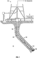
- FIG. 1 there is shown an embodiment of a drilling system 10 utilizing a bottomhole assembly (BHA) 60 configured for drilling wellbores. While a land system is shown, the teachings of the present disclosure may also be utilized in offshore or subsea applications.
- BHA bottomhole assembly
- FIG.1 a laminated earth formation 11 is intersected by a wellbore 12.
- the BHA 60 is conveyed via a drill string 22 into the wellbore 12.
- the drill string 22 may be jointed drill pipe or coiled tubing, which may include embedded conductors for power and / or data for providing signal and / or power communication between the surface and downhole equipment.
- the BHA 60 may include a drill bit 62 for forming the wellbore 12.
- the BHA 60 may include one or more rotary power sources such as a drilling motor 120.
- a pressurized drilling fluid is pumped down to the BHA 60 from the surface via the drill string 22.
- This flowing drilling fluid may be utilized to energize the drilling motor 120 , which generates rotary power that rotates the drill bit 62.
- the flowing drilling mud can also energize turbines or other similar devices that extract energy from the flowing drilling fluid.
- the extracted energy may be utilized to generate electricity and / or pressure hydraulic fluids. It should be understood that generating rotary power (i.e ., generating useful torque) and electrical power generation and pressuring of fluids are merely illustrative of a variety of functions that may be performed by a consumer of rotary power.
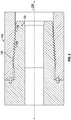
- the threaded connection may include a pin end 150 and a box end 152.
- the pin end 150 has external threads 154 and the box end 152 has internal threads 156.
- the Fig. 2 connection may be used to connect the jointed pipe of the drill string 22 ( Fig. 1 ), the subs and other components of the BHA 60 ( Fig. 1 ), etc.
- the Fig. 2 connection may also be used in any other well tools including, but are not limited to, under-reamers, reamers, pipe cutting tools, etc.
- a root 158 of a thread profile of the external thread 154 refers to the thread form or configuration of a thread in an axial plane and which is generally considered to include a crest, a root, and flanks.
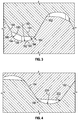
- the stress concentration at the root 158 is influenced by a length of a radius defining one or more circular arcs of a surface 160 between a load flank 162 and a trailing flank 164 of a thread, , e.g ., thread 154.
- the radius of a circle is the length of the line from the center to any point on its edge. Typically, the stress decreases with increased radius length.
- a radius of a root is the same as referring to a circular arc defined by that radius; i.e., such references are to be considered interchangeable.
- a root of a thread profile is said to have a specified radius, it is meant that at least a portion of a surface defining that root follows a circular arc defined by the specified radius. The length of an arc depends on both radius and a spanning angle.
- Embodiment of the present disclosure use a combination of radii (hereafter, Combined Curve Rounding - CCR) with increased radius lengths to thereby increase the corresponding radius curvature at selected locations along the surface 160 joining the load flank 162 and the trailing flank 164.
- the surface 160 joining the load flank 162 and the trailing flank 164 is defined by arcs 180 , 182 , 184 , each having a radius 190 , 192 , 194.
- CCR involves placing a relatively small "sharp" radius at the less critical positions of the thread root (e.g ., immediately adjacent to the flanks) and increasing the radius at the more critical position - typically in the medial portion, or middle, of the root 158.
- the radius 190 may be 0.70 mm
- the radius 192 may be 1.8 mm
- the radius 194 may be 0.60 mm.
- the critical maximum radius at the thread root 158 may be increased by more than 50% (from 1.15mm to 1.8mm).
- the depth of the thread profile is slightly reduced and thus consumes less radial space for pin and box threads.
- a thread profile using CCR at the thread root 158 may include 2 different radii (e.g., R1 and R2). Radius R1 200 may be at least 1.5 times larger than Radius R2 202. Referring to Fig. 5A , in another embodiment, a thread profile may use three radii (R1, R2 and R3). In such embodiments, Radius R1 206 may be two to four times larger than Radius R2 208 and two to four times larger than R3 210. The smaller radii (R2 208 and R3 210 ) may be on opposing sides of the largest radius (R1 206 ) .
- All of the radii are preferably connected tangentially among themselves.
- the straight load flank 162 may be tangentially connected to a smaller radius (R2).
- the smaller radius R3 may either be tangentially connected directly to the trailing flank 164.
- the arcs of each radius R1, R2, R3 connect at end points.
- tangentially connected it is meant that a tangent line of each radius at an end point is substantially aligned; e.g ., less than 10 degrees angular misalignment.
- the arc associated with radius R2 208 may cover about 25° to 45° and the arc associated with the radius R1 206 may cover about 35° to 65°.
- a run-out at an angle ⁇ R3 220 may be smaller than an angle ⁇ SF 222 of the trailing flank 164.
- the load flank 162 may include a tangential connection as described previously.
- the ⁇ R3 220 , ⁇ SF 222 may be with reference to a plane 224 that is orthogonal to a longitudinal axis 226 ( Fig. 2 ) of the connection.
- the threads may be cold worked to increase of fatigue resistance, copper plated to increase of galling resistance, and/or shot peened to increase resistance against stress/corrosion/cracking.
- the threads may also include stress relief groove(s) to increase of fatigue resistance.
Landscapes
- Engineering & Computer Science (AREA)
- Geology (AREA)
- Life Sciences & Earth Sciences (AREA)
- Mining & Mineral Resources (AREA)
- Mechanical Engineering (AREA)
- Physics & Mathematics (AREA)
- Environmental & Geological Engineering (AREA)
- Fluid Mechanics (AREA)
- General Life Sciences & Earth Sciences (AREA)
- Geochemistry & Mineralogy (AREA)
- General Engineering & Computer Science (AREA)
- Earth Drilling (AREA)
- Surgical Instruments (AREA)
- Non-Disconnectible Joints And Screw-Threaded Joints (AREA)
Claims (8)
- Raccord fileté, comprenant :une extrémité mâle (150) possédant des filetages externes (154) ;une extrémité femelle (152) possédant des filetages internes (156) qui sont complémentaires aux filetages externes (154) ; etun profil de filetage qui définit au moins une partie de l'un parmi les filetages internes (156) et les filetages externes (154), le profil de filetage comprenant une base de filetage (158) reliant un premier flanc (162) à un deuxième flanc (164), la base de filetage (158) étant au moins partiellement définie par une pluralité de rayons interreliés tangentiellement, la pluralité de rayons incluant au moins :- un rayon médian (192, 206),- un premier rayon distal (190, 208) sur un côté du rayon médian (192, 206) et- un deuxième rayon distal (194, 210) sur l'autre côté du rayon médian (192, 206), le rayon médian (192, 206) étant plus grand que le premier et que le deuxième rayon distal (194, 210), le premier rayon distal (190, 206) possédant une longueur différente de celle du deuxième rayon distal (194, 210) ;le premier rayon distal (190, 208) étant relié tangentiellement au premier flanc (162) au niveau d'un premier raccord tangentiel et le deuxième rayon distal (194, 210) étant relié tangentiellement au deuxième flanc (164) au niveau d'un deuxième raccord tangentiel et une ligne tangente associée à au moins l'un parmi le premier raccord tangentiel et le deuxième raccord tangentiel étant alignée sur l'un parmi les premier et deuxième flancs (164).
- Raccord selon la revendication 1, le rayon médian (206) étant entre deux et quatre fois plus grand que l'un parmi le premier rayon distal (208) et le deuxième rayon distal (210).
- Raccord selon la revendication 1, chacun parmi la pluralité des rayons définissant un arc circulaire.
- Raccord selon la revendication 1, chaque rayon possédant un arc associé, les arcs se reliant les uns aux autres au niveau d'extrémités et les lignes tangentes de deux rayons étant sensiblement alignées au niveau de chaque extrémité.
- Raccord fileté selon la revendication 1, l'extrémité mâle (150) et l'extrémité femelle (152) étant disposées le long de l'un parmi : (a) un train de forage et (b) un ensemble de fond de trou.
- Raccord selon la revendication 1, le deuxième rayon distal (194, 210) étant relié au deuxième flanc (164) sous un angle plus petit qu'un angle définissant une surface externe du deuxième flanc (164).
- Procédé de formation d'un raccord fileté, comprenant :la formation d'une extrémité mâle (150) pour qu'elle possède des filetages externes (154) ;la formation d'une extrémité femelle (152) pour qu'elle possède des filetages internes (156) qui sont complémentaires aux filetages externes (154), un profil de filetage étant réalisé, qui définit au moins une partie de l'un parmi les filetages internes (156) et les filetages externes (154) et qui inclut une base de filetage (158) reliant un premier flanc (162) à un deuxième flanc (164) et la base de filetage (158) étant au moins partiellement définie par une pluralité de rayons interreliés tangentiellement, la pluralité de rayons incluant au moins :- un rayon médian (192, 206),- un premier rayon distal (190, 208) sur un côté du rayon médian (192, 206) ; et- un deuxième rayon distal (194, 210) sur l'autre côté du rayon médian (192, 206), le rayon médian (192, 206) étant plus grand que le premier et que le deuxième rayon distal (194, 210), le premier rayon distal (190, 206) possédant une longueur différente de celle du deuxième rayon distal (194, 210),le premier rayon distal (190, 208) étant relié tangentiellement au premier flanc (162) au niveau d'un premier raccord tangentiel et le deuxième rayon distal (194, 210) étant relié tangentiellement au deuxième flanc (164) au niveau d'un deuxième raccord tangentiel et une ligne tangente associée à au moins l'un parmi le premier raccord tangentiel et le deuxième raccord tangentiel étant alignée sur l'un parmi les premier et deuxième flancs (164).
- Procédé selon la revendication 7, le rayon médian (206) étant entre deux et quatre fois plus grand que l'un parmi le premier rayon distal (208) et le deuxième rayon distal (210).
Applications Claiming Priority (2)
| Application Number | Priority Date | Filing Date | Title |
|---|---|---|---|
| US14/448,385 US9874058B2 (en) | 2014-07-31 | 2014-07-31 | Fatigue resistant thread profile with combined curve rounding |
| PCT/US2015/042629 WO2016018997A1 (fr) | 2014-07-31 | 2015-07-29 | Profil de filet résistant à la fatigue ayant une combinaison d'arrondi et de courbe |
Publications (3)
| Publication Number | Publication Date |
|---|---|
| EP3194703A1 EP3194703A1 (fr) | 2017-07-26 |
| EP3194703A4 EP3194703A4 (fr) | 2018-03-21 |
| EP3194703B1 true EP3194703B1 (fr) | 2019-11-06 |
Family
ID=55179508
Family Applications (1)
| Application Number | Title | Priority Date | Filing Date |
|---|---|---|---|
| EP15827231.0A Active EP3194703B1 (fr) | 2014-07-31 | 2015-07-29 | Profil de filet résistant à la fatigue ayant une combinaison d'arrondi et de courbe |
Country Status (7)
| Country | Link |
|---|---|
| US (1) | US9874058B2 (fr) |
| EP (1) | EP3194703B1 (fr) |
| CN (1) | CN106574489B (fr) |
| BR (1) | BR112017001393B1 (fr) |
| RU (1) | RU2700744C2 (fr) |
| SA (1) | SA517380788B1 (fr) |
| WO (1) | WO2016018997A1 (fr) |
Families Citing this family (8)
| Publication number | Priority date | Publication date | Assignee | Title |
|---|---|---|---|---|
| US10184597B2 (en) * | 2016-10-13 | 2019-01-22 | Forum Us, Inc | Stress reducing thread form |
| US10669787B2 (en) * | 2016-12-09 | 2020-06-02 | Schlumberger Technology Corporation | Pump rod connection |
| UA124780C2 (uk) * | 2017-03-31 | 2021-11-17 | Ніппон Стіл Корпорейшн | Нарізне з'єднання для сталевої труби |
| EP3536893B1 (fr) * | 2018-03-09 | 2020-09-30 | Sandvik Mining and Construction Tools AB | Raccord pour forage à percussion |
| UA128488C2 (uk) * | 2019-03-27 | 2024-07-24 | Ніппон Стіл Корпорейшн | Нарізне з'єднання для сталевої труби |
| WO2020247923A1 (fr) | 2019-06-06 | 2020-12-10 | Fermata Technologies, Llc | Ajustement de forme de filetage arqué |
| WO2021131177A1 (fr) * | 2019-12-26 | 2021-07-01 | Jfeスチール株式会社 | Raccord fileté pour tubes |
| US11426803B2 (en) | 2020-09-08 | 2022-08-30 | Iscar, Ltd. | Replaceable cutting head having external thread with concavely curved root and rotary cutting tool |
Family Cites Families (26)
| Publication number | Priority date | Publication date | Assignee | Title |
|---|---|---|---|---|
| US4004832A (en) | 1975-09-19 | 1977-01-25 | United States Steel Corporation | Thread form for pipe joints |
| US4549754A (en) | 1983-06-20 | 1985-10-29 | Reed Tubular Products Company | Tool joint |
| FR2624931B1 (fr) | 1987-12-18 | 1990-06-01 | Simmonds Sa | Element filete perfectionne formant par exemple une vis, et assemblage de pieces realise a l'aide de cet element |
| US4799844A (en) | 1988-01-11 | 1989-01-24 | Trw Inc | Elliptical thread design |
| US5060740A (en) * | 1990-05-29 | 1991-10-29 | Sandvik Rock Tools, Inc. | Screw thread coupling |
| US5735658A (en) | 1993-12-13 | 1998-04-07 | Haerle; Anton | Thread forming tool |
| US5931511A (en) | 1997-05-02 | 1999-08-03 | Grant Prideco, Inc. | Threaded connection for enhanced fatigue resistance |
| US6030004A (en) * | 1997-12-08 | 2000-02-29 | Shaw Industries | High torque threaded tool joint for drill pipe and other drill stem components |
| ATE266796T1 (de) * | 1998-10-01 | 2004-05-15 | Boart Hwf Gmbh Co Kg | Bohrgestänge zum drehschlagbohren, insbesondere zum überlagerungsbohren |
| US6467818B1 (en) | 1999-10-01 | 2002-10-22 | Grant Prideco, L.P. | Drill collar box |
| FR2807138B1 (fr) | 2000-03-31 | 2002-05-17 | Vallourec Mannesmann Oil & Gas | Element filete tubulaire pour joint filete tubulaire resistant a la fatigue et joint filete tubulaire resultant |
| US20050161259A1 (en) | 2004-01-26 | 2005-07-28 | Anmol Kaul | Unsymmetrical profile threads for use in a positive displacement motor housing |
| US7455329B2 (en) | 2004-01-29 | 2008-11-25 | Grant Prideco, L.P. | Fast make-up fatigue resistant rotary shouldered connection |
| US7549682B2 (en) * | 2005-09-19 | 2009-06-23 | Vetco Gray Inc. | Threaded pipe connector |
| US7690697B2 (en) | 2007-05-09 | 2010-04-06 | Gandy Technologies Corp. | Thread form for tubular connections |
| SE0701371L (sv) * | 2007-06-05 | 2008-03-11 | Sandvik Intellectual Property | Bergborrutrustning samt hon- och handelar därtill |
| WO2009023168A2 (fr) | 2007-08-13 | 2009-02-19 | Research Engineering & Manufacturing, Inc. | Pièce de fixation formant filet |
| EP2028402B1 (fr) | 2007-08-24 | 2010-09-01 | Tenaris Connections Aktiengesellschaft | Procédé pour améliorer la résistance à la fatigue d'un joint fileté |
| EP2028403B1 (fr) | 2007-08-24 | 2011-04-13 | Tenaris Connections Aktiengesellschaft | Joint fileté doté de charges radiales élevées et de surfaces traitées différentiellement |
| US7731466B2 (en) | 2007-11-02 | 2010-06-08 | Gm Global Technology Operations, Inc. | Thread profile modification for controlled stiffness |
| US20110012347A1 (en) | 2009-07-14 | 2011-01-20 | HDD Rotary Sales LLC | Threaded Tool Joint Connection |
| FR2953272B1 (fr) | 2009-11-30 | 2011-12-16 | Vallourec Mannesmann Oil & Gas | Joint filete |
| EP2541078A1 (fr) | 2010-02-26 | 2013-01-02 | Art Screw Co., Ltd. | Élément de fixation et structure de fixation |
| FR2969738B1 (fr) | 2010-12-28 | 2016-03-25 | Vallourec Mannesmann Oil & Gas | Joint filete pour le forage et l'exploitation des puits d'hydrocarbures |
| SE535814C2 (sv) * | 2011-05-20 | 2013-01-02 | Atlas Copco Secoroc Ab | Gänganordning, gängförband samt borrsträngskomponent för slående bergborrning |
| US8668232B2 (en) | 2011-12-09 | 2014-03-11 | Tenaris Connections Limited | Threaded connection with improved root thread profile |
-
2014
- 2014-07-31 US US14/448,385 patent/US9874058B2/en active Active
-
2015
- 2015-07-29 BR BR112017001393-2A patent/BR112017001393B1/pt active IP Right Grant
- 2015-07-29 RU RU2017104423A patent/RU2700744C2/ru active
- 2015-07-29 WO PCT/US2015/042629 patent/WO2016018997A1/fr not_active Ceased
- 2015-07-29 CN CN201580040163.5A patent/CN106574489B/zh active Active
- 2015-07-29 EP EP15827231.0A patent/EP3194703B1/fr active Active
-
2017
- 2017-01-24 SA SA517380788A patent/SA517380788B1/ar unknown
Non-Patent Citations (1)
| Title |
|---|
| None * |
Also Published As
| Publication number | Publication date |
|---|---|
| EP3194703A4 (fr) | 2018-03-21 |
| RU2017104423A (ru) | 2018-08-28 |
| BR112017001393B1 (pt) | 2022-03-03 |
| RU2700744C2 (ru) | 2019-09-19 |
| US20160032663A1 (en) | 2016-02-04 |
| US9874058B2 (en) | 2018-01-23 |
| CN106574489A (zh) | 2017-04-19 |
| WO2016018997A1 (fr) | 2016-02-04 |
| BR112017001393A2 (pt) | 2017-11-21 |
| RU2017104423A3 (fr) | 2019-01-28 |
| EP3194703A1 (fr) | 2017-07-26 |
| CN106574489B (zh) | 2019-03-26 |
| SA517380788B1 (ar) | 2021-12-26 |
Similar Documents
| Publication | Publication Date | Title |
|---|---|---|
| US9874058B2 (en) | Fatigue resistant thread profile with combined curve rounding | |
| US10436357B2 (en) | Connecting oil country tubular goods | |
| CN104812990B (zh) | 具有螺旋延伸的扭矩肩部的管状连接件 | |
| NL1041835B1 (en) | Running tool lock mechanism. | |
| CN103282708B (zh) | 用于油气井钻井和采油的螺纹接头 | |
| CN113216869B (zh) | 带螺纹且联接的管材连接 | |
| EA027230B1 (ru) | Соединение с конусными шлицами для бурильной трубы, обсадной трубы и насосно-компрессорной трубы | |
| EP3247864B1 (fr) | Profil de filet équilibré, éléments tubulaires employant celui-ci et procédés s'y rapportant | |
| US20100018699A1 (en) | Low Stress Threadform with a Non-conic Section Curve | |
| EP3784868A1 (fr) | Raccord fileté cunéiforme pour biens tubulaires | |
| CA2469875C (fr) | Raccord filete modulaire presentant une haute resistance a la fatigue | |
| WO2019170436A1 (fr) | Accouplement destiné à raccorder des éléments tubulaires de fond de trou | |
| WO2017215183A1 (fr) | Raccord de tige de forage à torsion élevée | |
| US11396962B2 (en) | Arcuate thread form fit | |
| US20150093189A1 (en) | Multi-start thread connection for downhole tools | |
| US11204115B2 (en) | Threaded connections for tubular members | |
| US10731423B2 (en) | Multi-start thread connection for downhole tools | |
| EP3545162B1 (fr) | Raccord à filets multiples pour outils de fond de trou | |
| WO2011023557A1 (fr) | Couplages souples pour éléments tubulaires | |
| US20070151739A1 (en) | Connector for use in a wellbore | |
| WO2013033684A1 (fr) | Joint de tige de tige de forage |
Legal Events
| Date | Code | Title | Description |
|---|---|---|---|
| STAA | Information on the status of an ep patent application or granted ep patent |
Free format text: STATUS: THE INTERNATIONAL PUBLICATION HAS BEEN MADE |
|
| PUAI | Public reference made under article 153(3) epc to a published international application that has entered the european phase |
Free format text: ORIGINAL CODE: 0009012 |
|
| STAA | Information on the status of an ep patent application or granted ep patent |
Free format text: STATUS: REQUEST FOR EXAMINATION WAS MADE |
|
| 17P | Request for examination filed |
Effective date: 20170224 |
|
| AK | Designated contracting states |
Kind code of ref document: A1 Designated state(s): AL AT BE BG CH CY CZ DE DK EE ES FI FR GB GR HR HU IE IS IT LI LT LU LV MC MK MT NL NO PL PT RO RS SE SI SK SM TR |
|
| AX | Request for extension of the european patent |
Extension state: BA ME |
|
| DAV | Request for validation of the european patent (deleted) | ||
| DAX | Request for extension of the european patent (deleted) | ||
| A4 | Supplementary search report drawn up and despatched |
Effective date: 20180221 |
|
| RIC1 | Information provided on ipc code assigned before grant |
Ipc: F16L 15/06 20060101ALI20180215BHEP Ipc: E21B 17/042 20060101AFI20180215BHEP Ipc: E21B 19/16 20060101ALI20180215BHEP |
|
| STAA | Information on the status of an ep patent application or granted ep patent |
Free format text: STATUS: EXAMINATION IS IN PROGRESS |
|
| 17Q | First examination report despatched |
Effective date: 20181217 |
|
| GRAP | Despatch of communication of intention to grant a patent |
Free format text: ORIGINAL CODE: EPIDOSNIGR1 |
|
| STAA | Information on the status of an ep patent application or granted ep patent |
Free format text: STATUS: GRANT OF PATENT IS INTENDED |
|
| INTG | Intention to grant announced |
Effective date: 20190514 |
|
| RAP1 | Party data changed (applicant data changed or rights of an application transferred) |
Owner name: BAKER HUGHES, A GE COMPANY, LLC |
|
| GRAS | Grant fee paid |
Free format text: ORIGINAL CODE: EPIDOSNIGR3 |
|
| GRAA | (expected) grant |
Free format text: ORIGINAL CODE: 0009210 |
|
| STAA | Information on the status of an ep patent application or granted ep patent |
Free format text: STATUS: THE PATENT HAS BEEN GRANTED |
|
| AK | Designated contracting states |
Kind code of ref document: B1 Designated state(s): AL AT BE BG CH CY CZ DE DK EE ES FI FR GB GR HR HU IE IS IT LI LT LU LV MC MK MT NL NO PL PT RO RS SE SI SK SM TR |
|
| REG | Reference to a national code |
Ref country code: GB Ref legal event code: FG4D |
|
| REG | Reference to a national code |
Ref country code: CH Ref legal event code: EP Ref country code: AT Ref legal event code: REF Ref document number: 1198948 Country of ref document: AT Kind code of ref document: T Effective date: 20191115 |
|
| REG | Reference to a national code |
Ref country code: DE Ref legal event code: R096 Ref document number: 602015041316 Country of ref document: DE |
|
| REG | Reference to a national code |
Ref country code: IE Ref legal event code: FG4D |
|
| REG | Reference to a national code |
Ref country code: NO Ref legal event code: T2 Effective date: 20191106 |
|
| REG | Reference to a national code |
Ref country code: NL Ref legal event code: MP Effective date: 20191106 |
|
| REG | Reference to a national code |
Ref country code: LT Ref legal event code: MG4D |
|
| PG25 | Lapsed in a contracting state [announced via postgrant information from national office to epo] |
Ref country code: BG Free format text: LAPSE BECAUSE OF FAILURE TO SUBMIT A TRANSLATION OF THE DESCRIPTION OR TO PAY THE FEE WITHIN THE PRESCRIBED TIME-LIMIT Effective date: 20200206 Ref country code: LT Free format text: LAPSE BECAUSE OF FAILURE TO SUBMIT A TRANSLATION OF THE DESCRIPTION OR TO PAY THE FEE WITHIN THE PRESCRIBED TIME-LIMIT Effective date: 20191106 Ref country code: PL Free format text: LAPSE BECAUSE OF FAILURE TO SUBMIT A TRANSLATION OF THE DESCRIPTION OR TO PAY THE FEE WITHIN THE PRESCRIBED TIME-LIMIT Effective date: 20191106 Ref country code: GR Free format text: LAPSE BECAUSE OF FAILURE TO SUBMIT A TRANSLATION OF THE DESCRIPTION OR TO PAY THE FEE WITHIN THE PRESCRIBED TIME-LIMIT Effective date: 20200207 Ref country code: SE Free format text: LAPSE BECAUSE OF FAILURE TO SUBMIT A TRANSLATION OF THE DESCRIPTION OR TO PAY THE FEE WITHIN THE PRESCRIBED TIME-LIMIT Effective date: 20191106 Ref country code: LV Free format text: LAPSE BECAUSE OF FAILURE TO SUBMIT A TRANSLATION OF THE DESCRIPTION OR TO PAY THE FEE WITHIN THE PRESCRIBED TIME-LIMIT Effective date: 20191106 Ref country code: FI Free format text: LAPSE BECAUSE OF FAILURE TO SUBMIT A TRANSLATION OF THE DESCRIPTION OR TO PAY THE FEE WITHIN THE PRESCRIBED TIME-LIMIT Effective date: 20191106 Ref country code: PT Free format text: LAPSE BECAUSE OF FAILURE TO SUBMIT A TRANSLATION OF THE DESCRIPTION OR TO PAY THE FEE WITHIN THE PRESCRIBED TIME-LIMIT Effective date: 20200306 Ref country code: NL Free format text: LAPSE BECAUSE OF FAILURE TO SUBMIT A TRANSLATION OF THE DESCRIPTION OR TO PAY THE FEE WITHIN THE PRESCRIBED TIME-LIMIT Effective date: 20191106 |
|
| PG25 | Lapsed in a contracting state [announced via postgrant information from national office to epo] |
Ref country code: IS Free format text: LAPSE BECAUSE OF FAILURE TO SUBMIT A TRANSLATION OF THE DESCRIPTION OR TO PAY THE FEE WITHIN THE PRESCRIBED TIME-LIMIT Effective date: 20200306 Ref country code: HR Free format text: LAPSE BECAUSE OF FAILURE TO SUBMIT A TRANSLATION OF THE DESCRIPTION OR TO PAY THE FEE WITHIN THE PRESCRIBED TIME-LIMIT Effective date: 20191106 Ref country code: RS Free format text: LAPSE BECAUSE OF FAILURE TO SUBMIT A TRANSLATION OF THE DESCRIPTION OR TO PAY THE FEE WITHIN THE PRESCRIBED TIME-LIMIT Effective date: 20191106 |
|
| PG25 | Lapsed in a contracting state [announced via postgrant information from national office to epo] |
Ref country code: AL Free format text: LAPSE BECAUSE OF FAILURE TO SUBMIT A TRANSLATION OF THE DESCRIPTION OR TO PAY THE FEE WITHIN THE PRESCRIBED TIME-LIMIT Effective date: 20191106 |
|
| PG25 | Lapsed in a contracting state [announced via postgrant information from national office to epo] |
Ref country code: ES Free format text: LAPSE BECAUSE OF FAILURE TO SUBMIT A TRANSLATION OF THE DESCRIPTION OR TO PAY THE FEE WITHIN THE PRESCRIBED TIME-LIMIT Effective date: 20191106 Ref country code: CZ Free format text: LAPSE BECAUSE OF FAILURE TO SUBMIT A TRANSLATION OF THE DESCRIPTION OR TO PAY THE FEE WITHIN THE PRESCRIBED TIME-LIMIT Effective date: 20191106 Ref country code: DK Free format text: LAPSE BECAUSE OF FAILURE TO SUBMIT A TRANSLATION OF THE DESCRIPTION OR TO PAY THE FEE WITHIN THE PRESCRIBED TIME-LIMIT Effective date: 20191106 Ref country code: RO Free format text: LAPSE BECAUSE OF FAILURE TO SUBMIT A TRANSLATION OF THE DESCRIPTION OR TO PAY THE FEE WITHIN THE PRESCRIBED TIME-LIMIT Effective date: 20191106 Ref country code: EE Free format text: LAPSE BECAUSE OF FAILURE TO SUBMIT A TRANSLATION OF THE DESCRIPTION OR TO PAY THE FEE WITHIN THE PRESCRIBED TIME-LIMIT Effective date: 20191106 |
|
| REG | Reference to a national code |
Ref country code: DE Ref legal event code: R097 Ref document number: 602015041316 Country of ref document: DE |
|
| REG | Reference to a national code |
Ref country code: AT Ref legal event code: MK05 Ref document number: 1198948 Country of ref document: AT Kind code of ref document: T Effective date: 20191106 |
|
| PG25 | Lapsed in a contracting state [announced via postgrant information from national office to epo] |
Ref country code: SM Free format text: LAPSE BECAUSE OF FAILURE TO SUBMIT A TRANSLATION OF THE DESCRIPTION OR TO PAY THE FEE WITHIN THE PRESCRIBED TIME-LIMIT Effective date: 20191106 Ref country code: SK Free format text: LAPSE BECAUSE OF FAILURE TO SUBMIT A TRANSLATION OF THE DESCRIPTION OR TO PAY THE FEE WITHIN THE PRESCRIBED TIME-LIMIT Effective date: 20191106 |
|
| PLBE | No opposition filed within time limit |
Free format text: ORIGINAL CODE: 0009261 |
|
| STAA | Information on the status of an ep patent application or granted ep patent |
Free format text: STATUS: NO OPPOSITION FILED WITHIN TIME LIMIT |
|
| 26N | No opposition filed |
Effective date: 20200807 |
|
| PG25 | Lapsed in a contracting state [announced via postgrant information from national office to epo] |
Ref country code: AT Free format text: LAPSE BECAUSE OF FAILURE TO SUBMIT A TRANSLATION OF THE DESCRIPTION OR TO PAY THE FEE WITHIN THE PRESCRIBED TIME-LIMIT Effective date: 20191106 Ref country code: SI Free format text: LAPSE BECAUSE OF FAILURE TO SUBMIT A TRANSLATION OF THE DESCRIPTION OR TO PAY THE FEE WITHIN THE PRESCRIBED TIME-LIMIT Effective date: 20191106 |
|
| PG25 | Lapsed in a contracting state [announced via postgrant information from national office to epo] |
Ref country code: IT Free format text: LAPSE BECAUSE OF FAILURE TO SUBMIT A TRANSLATION OF THE DESCRIPTION OR TO PAY THE FEE WITHIN THE PRESCRIBED TIME-LIMIT Effective date: 20191106 |
|
| REG | Reference to a national code |
Ref country code: DE Ref legal event code: R119 Ref document number: 602015041316 Country of ref document: DE |
|
| PG25 | Lapsed in a contracting state [announced via postgrant information from national office to epo] |
Ref country code: MC Free format text: LAPSE BECAUSE OF FAILURE TO SUBMIT A TRANSLATION OF THE DESCRIPTION OR TO PAY THE FEE WITHIN THE PRESCRIBED TIME-LIMIT Effective date: 20191106 |
|
| REG | Reference to a national code |
Ref country code: CH Ref legal event code: PL |
|
| REG | Reference to a national code |
Ref country code: BE Ref legal event code: MM Effective date: 20200731 |
|
| PG25 | Lapsed in a contracting state [announced via postgrant information from national office to epo] |
Ref country code: CH Free format text: LAPSE BECAUSE OF NON-PAYMENT OF DUE FEES Effective date: 20200731 Ref country code: LU Free format text: LAPSE BECAUSE OF NON-PAYMENT OF DUE FEES Effective date: 20200729 Ref country code: LI Free format text: LAPSE BECAUSE OF NON-PAYMENT OF DUE FEES Effective date: 20200731 Ref country code: FR Free format text: LAPSE BECAUSE OF NON-PAYMENT OF DUE FEES Effective date: 20200731 |
|
| PG25 | Lapsed in a contracting state [announced via postgrant information from national office to epo] |
Ref country code: BE Free format text: LAPSE BECAUSE OF NON-PAYMENT OF DUE FEES Effective date: 20200731 Ref country code: DE Free format text: LAPSE BECAUSE OF NON-PAYMENT OF DUE FEES Effective date: 20210202 |
|
| PG25 | Lapsed in a contracting state [announced via postgrant information from national office to epo] |
Ref country code: IE Free format text: LAPSE BECAUSE OF NON-PAYMENT OF DUE FEES Effective date: 20200729 |
|
| PG25 | Lapsed in a contracting state [announced via postgrant information from national office to epo] |
Ref country code: TR Free format text: LAPSE BECAUSE OF FAILURE TO SUBMIT A TRANSLATION OF THE DESCRIPTION OR TO PAY THE FEE WITHIN THE PRESCRIBED TIME-LIMIT Effective date: 20191106 Ref country code: MT Free format text: LAPSE BECAUSE OF FAILURE TO SUBMIT A TRANSLATION OF THE DESCRIPTION OR TO PAY THE FEE WITHIN THE PRESCRIBED TIME-LIMIT Effective date: 20191106 Ref country code: CY Free format text: LAPSE BECAUSE OF FAILURE TO SUBMIT A TRANSLATION OF THE DESCRIPTION OR TO PAY THE FEE WITHIN THE PRESCRIBED TIME-LIMIT Effective date: 20191106 |
|
| PG25 | Lapsed in a contracting state [announced via postgrant information from national office to epo] |
Ref country code: MK Free format text: LAPSE BECAUSE OF FAILURE TO SUBMIT A TRANSLATION OF THE DESCRIPTION OR TO PAY THE FEE WITHIN THE PRESCRIBED TIME-LIMIT Effective date: 20191106 |
|
| P01 | Opt-out of the competence of the unified patent court (upc) registered |
Effective date: 20230526 |
|
| PGFP | Annual fee paid to national office [announced via postgrant information from national office to epo] |
Ref country code: GB Payment date: 20250619 Year of fee payment: 11 |
|
| PGFP | Annual fee paid to national office [announced via postgrant information from national office to epo] |
Ref country code: NO Payment date: 20250623 Year of fee payment: 11 |