EP3194854B1 - Haushaltsofen - Google Patents
Haushaltsofen Download PDFInfo
- Publication number
- EP3194854B1 EP3194854B1 EP15760277.2A EP15760277A EP3194854B1 EP 3194854 B1 EP3194854 B1 EP 3194854B1 EP 15760277 A EP15760277 A EP 15760277A EP 3194854 B1 EP3194854 B1 EP 3194854B1
- Authority
- EP
- European Patent Office
- Prior art keywords
- oven
- radial fan
- resistance wire
- fan
- radial
- Prior art date
- Legal status (The legal status is an assumption and is not a legal conclusion. Google has not performed a legal analysis and makes no representation as to the accuracy of the status listed.)
- Active
Links
Images



Classifications
-
- F—MECHANICAL ENGINEERING; LIGHTING; HEATING; WEAPONS; BLASTING
- F24—HEATING; RANGES; VENTILATING
- F24C—DOMESTIC STOVES OR RANGES ; DETAILS OF DOMESTIC STOVES OR RANGES, OF GENERAL APPLICATION
- F24C15/00—Details
- F24C15/32—Arrangements of ducts for hot gases, e.g. in or around baking ovens
- F24C15/322—Arrangements of ducts for hot gases, e.g. in or around baking ovens with forced circulation
- F24C15/325—Arrangements of ducts for hot gases, e.g. in or around baking ovens with forced circulation electrically-heated
-
- F—MECHANICAL ENGINEERING; LIGHTING; HEATING; WEAPONS; BLASTING
- F24—HEATING; RANGES; VENTILATING
- F24C—DOMESTIC STOVES OR RANGES ; DETAILS OF DOMESTIC STOVES OR RANGES, OF GENERAL APPLICATION
- F24C15/00—Details
- F24C15/006—Arrangements for circulation of cooling air
-
- F—MECHANICAL ENGINEERING; LIGHTING; HEATING; WEAPONS; BLASTING
- F24—HEATING; RANGES; VENTILATING
- F24C—DOMESTIC STOVES OR RANGES ; DETAILS OF DOMESTIC STOVES OR RANGES, OF GENERAL APPLICATION
- F24C15/00—Details
- F24C15/32—Arrangements of ducts for hot gases, e.g. in or around baking ovens
- F24C15/322—Arrangements of ducts for hot gases, e.g. in or around baking ovens with forced circulation
- F24C15/327—Arrangements of ducts for hot gases, e.g. in or around baking ovens with forced circulation with air moisturising
Definitions
- the present invention relates to a domestic oven for cooking food.
- Ventilated domestic ovens are already known, i.e. ovens which provide the possibility of a so-called ventilated cooking system which allows to uniform the temperature inside the oven.
- the ventilation is performed by an axial fan which conveys air onto an electric resistor positioned near the fan itself.
- the air is heated, runs along the walls of the compartment and, once reached the door of the oven, is aspirated by the fan center to be pushed onto the electric resistor again.
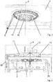
- the fan-resistor system is positioned on the wall opposite to the cavity door, as diagrammatically shown in Fig. 1 .
- this configuration may generate an asymmetric air flow which leads to an imbalanced heat distribution at the walls of the oven compartment.
- the fan, the electric resistor and the resistor support are disadvantageously assembled in the cavity of the oven at different times and according to different methods.
- Document EP1550828 discloses a domestic oven provided with a steam generating unit.
- Another object of the invention is to make a domestic oven which also allows to improve the steam distribution inside the compartment if a steam diffusion device is provided inside the oven.
- the present invention thus aims to reach the object discussed above by making a domestic oven according to claim 1.
- the radial fan is positioned only on the roof of the cavity or inner compartment of the oven in the oven of the invention.
- a further advantage is that one or more spiral coiled resistance wires are provided near the roof, coaxially outside the radial fan.
- the use of these simple resistance wires instead of the classic tubular serpentine resistor allows to have a smaller mass and to improve system efficiency.
- Forced ventilation occurs because the air flows let out from the radial fan are directed onto the resistance wires, are heated and run along the roof and then downwards along the side walls of the compartment to reach the position of the tray or vessel containing the food. From the center of the tray, a resulting flow of air will go upwards again towards the center of the radial fan and the cycle will be repeated.
- the radial fan positioned on the roof, can be coupled to the fan which cools the electronics and the door of the oven, a single motor being provided for both fans.
- the oven has an inner compartment for cooking food, closed by a door, the oven comprising:
- the support structure comprises a flat surface and a protective lid, which jointly define a closed housing, inside which the at least one resistance wire and the fan are provided.
- the protective lid is provided with a least one series of first slots arranged peripherally, or laterally, along a respective circumference, at the at least one resistance wire for the radial ejection of air flows crossing said at least one resistance wire.
- the lid may also be provided with at least one series of second slots arranged centrally along a respective circumference, at the radial fan, for the passage of aspirated air from the inner compartment.
- one or more series of first slots can be provided arranged, for example, on circumferences at different axial heights along the rotation axis of the fan.
- the cover can have one or more series of second slots, arranged, for example, along respective concentric circumferences of different radius.
- the fan, the electric resistor and the support/protective lid of the resistor are mutually preassembled and form an integrated system, i.e. defining a single assembled component, which can be subsequently fitted in the oven cavity more simply and cost-effectively than in the prior art. Furthermore, there are advantages in terms of robustness and compactness by providing a preassembled component.
- FIGS. 2 to 4 show a first embodiment of a ventilated domestic oven, provided with an inner compartment for cooking food.
- a ventilated domestic oven provided with an inner compartment for cooking food.
- Such an oven comprises:
- the radial fan 1 is configured to take air in from the inner compartment along the direction of axis X and to expel, radially with respect to axis X, air flows directed towards said at least one resistance wire 3.
- Each resistance wire 3 which can be single or more than one, consists of either a single winding or two or more windings appropriately connected to one another.
- a support structure 4 which defines a closed housing, in which the radial fan 1 and the at least one resistance wire 3 are housed.
- the support structure 4 comprises a base 16, or a flat surface, and a protective lid 17.
- the base 16 is fixed to the upper wall 2, for example by means of screws.
- the protective lid 17 can be defined, for example, by a spherical zone, i.e. by a part of a spherical surface comprised between two parallel planes which cut the sphere or by a spherical cap surface.
- Such a protective lid 17 is provided with at least one series of first slots 14 arranged along a circumference.
- each series is arranged along a respective circumference.
- Such circumferences are preferably concentric and have a different radius from one another.
- a further air inlet slot 18 can be positioned at a central portion of the bottom of the lid, coaxial to the center of such circumferences.
- the number of the series of first and/or second slots can be varied.
- the support structure 4, radial fan 1 and at least one resistance wire 3 are preassembled so as to form a single component to be installed in the oven.
- a pipe 8 connected to a reservoir 10 outside the support structure 4 is provided inside the oven compartment, preferably but not necessarily on the support structure 4.
- a pipe is provided with a plurality of holes 9 facing towards the upper wall 2 for releasing steam.
- the pipe 8 is fed with water coming from the reservoir 10, by using a pump 21, producing steam which exits from the holes 9.
- the pipe 8 substantially circular in shape, is arranged between the at least one resistance wire 3 and the radial fan 1, coaxially to said radial fan 1.
- the pipe 8 is arranged adjacently between the single resistance wire 3 or one of the resistance wires 3 and a tubular electric resistor 7, of substantially circular shape and coaxial to the radial fan 1.
- the resistor 7 transmits heat to the pipe 8 by conduction, the pipe 8 and the resistor 7 being mechanically and thermally connected.
- the support structure 4 comprises a cavity facing towards the upper wall 2 of the compartment, having a circular bottom 5 for housing the radial fan 1 and a flared edge 6 onto which the single resistance wire 3 or the two or more resistance wires 3 are fixed by means of appropriate ceramic supports.
- the pipe 8, arranged between a resistance wire 3 and the radial fan 1, can be provided in a connection zone between the circular bottom 5 and the flared edge 6.
- the radial fan 1 is positioned so as to expel air flows, which at least partially brush the pipe 8 and the one or more resistance wires 3, and preferably also the tubular electric resistor 7, so as to heat and optimally distribute the air of the inner compartment of the oven and optimize the dispersion of steam released from the holes 9.
- the outlet sections of the bladed impeller of the radial fan 1 are arranged at a height or position corresponding at least partially to the height or position of the pipe 8, of the one or more resistance wires 3 and of the tubular electric resistor 7.
- a support structure may be provided as described for the first embodiment, comprising the base and the lid and the series of first and second slots.
- a further either radial or axial fan 12 is provided, configured to aspirate cool air from the outside of the oven and to expel air flows for cooling the electronics of the oven and of the door 22 of said oven.
- the further fan 12 is a radial fan arranged along the axis X itself and a single motor 13 is provided to actuate both the radial fan 1, which operates on the hot air of the oven and the radial cooling fan 12.
- an inner compartment for cooking food closed by a door is provided instead, the oven comprising:
- the radial fan 1 is configured to take air in from the inner compartment along the direction of axis Y and to expel, radially with respect to axis Y, air flows directed towards said at least one resistance wire.
- the resistance wire 3 which can be one or more than one, consists of either a single winding or two or more windings appropriately connected together.
- a support structure 4 of the radial fan 1' and of the at least one resistance wire 3 is provided.
- a pipe 8 connected to a reservoir 10 outside the support structure 4 is provided within the compartment of the oven, preferably but not necessarily on the support structure 4.
- Such a pipe is provided with a plurality of holes 9 (not shown in Figure 8 ) at least partially facing towards the upper wall 2 of the compartment to release steam.
- the pipe 8 is fed with water coming from the reservoir 10, by using a pump 21, producing steam which exits from the holes 9.
- the pipe 8 substantially circular in shape, is arranged between the at least one resistance wire 3 and the radial fan 1', coaxially to said radial fan 1'.
- the pipe 8 is arranged adjacently between the single resistance wire 3 or one of the resistance wires 3 and a tubular electric resistor 7, of substantially circular shape and coaxial to the radial fan 1'.
- the resistor 7 transmits heat to the pipe 8 by conduction, the pipe 8 and the resistor 7 being mechanically and thermally connected.
- the support structure 4 comprises a cavity facing towards the rear wall 20 of the compartment, having a circular bottom 5 for housing the radial fan 1' and a flared edge 6 onto which the single resistance wire 3 or the two or more resistance wires 3 are fixed by means of appropriate ceramic supports.
- the pipe 8, arranged between the one or more resistance wires 3 and the radial fan 1', can be provided in a connection zone between the circular bottom 5 and the flared edge 6.
- the radial fan 1' is positioned so as to expel air flows, which at least partially brush the pipe 8 and the one or more resistance wires 3, and preferably also the tubular electric resistor 7, so as to heat and distribute in optimal manner the air of the inner compartment of the oven and optimize the dispersion of steam released from the holes 9.
- the outlet sections of the bladed impeller of the radial fan 1' are arranged at least partially facing the pipe 8, the one or more resistance wires 3 and the tubular electric resistor 7.
- a further either radial or axial fan 12 is provided in such a cooling cavity 11, which fan is configured to aspirate cool air from the outside of the oven and to expel air flows for cooling the electronics of the oven and of the door 22 of said oven.
- a support structure can be provided as described for the first embodiment, comprising the base and the lid and the series of first and second slots.
Landscapes
- Engineering & Computer Science (AREA)
- Chemical & Material Sciences (AREA)
- Combustion & Propulsion (AREA)
- Mechanical Engineering (AREA)
- General Engineering & Computer Science (AREA)
- Electric Stoves And Ranges (AREA)
Claims (9)
- Haushaltsofen, der mit einem Innenraum zum Kochen von Speisen versehen ist, wobei der Ofen umfasst:- ein Radialgebläse (1), das eine Achse (X) definiert und um diese umläuft und ausschließlich an einer oberen Wand (2) des Innenraums angeordnet ist,- zumindest einen spiralförmig gewickelten Widerstandsdraht (3), der entlang eines entsprechenden Umfangs koaxial außerhalb des Radialgebläses (1) angeordnet ist,- wobei das Radialgebläse (1) ausgebildet ist, um Luft von dem Innenraum entlang der Richtung der Achse (X) einzusaugen und in Richtung zu dem zumindest einen Widerstandsdrahtes (3) hin gelenkte Luftströmungen radial mit Bezug auf die Achse (X) zu emittieren,wobei eine Tragstruktur (4) vorgesehen ist, um das Radialgebläse (1) und den zumindest einen Widerstandsdraht (3) zu tragen,
wobei die Tragstruktur ein Gehäuse (4) ist, in welchem das Radialgebläse (1) und der zumindest eine Widerstandsdraht (3) montiert sind, wobei das Gehäuse (4) an der oberen Wand (2) des Innenraums befestigt ist, dadurch gekennzeichnet, dass ein Rohr (8) in dem Gehäuse vorgesehen ist, wobei das Rohr (8) mit einem Reservoir (10) außerhalb der Tragstruktur (4) verbunden und mit einer Mehrzahl von Löchern (9) versehen ist, die der oberen Wand (2) zugewandt sind, um Dampf freizugeben,
wobei das Rohr (8) zwischen dem zumindest einen Widerstandsdraht (3) und dem Radialgebläse (1) koaxial zu dem Radialgebläse (1) angeordnet ist. - Ofen nach Anspruch 1, wobei das geschlossene Gehäuse (4) eine ebene Fläche (16), die an der oberen Wand (2) befestigt ist, und einen Schutzdeckel (17) umfasst, der einstückig an der ebenen Fläche (16) befestigt und mit zumindest einer Reihe von ersten Schlitzen (14) versehen ist, die in Umfangsrichtung entlang eines jeweiligen Umfangs an dem zumindest einen Widerstandsdraht (3) für das radiale Ausstoßen der Luftströmungen, die den zumindest einen Widerstandsdraht (3) queren, angeordnet sind.
- Ofen nach Anspruch 2, wobei der Schutzdeckel (17) mit zumindest einer Reihe von zweiten Schlitzen (15) versehen ist, die zentral entlang eines entsprechenden Umfangs an dem Radialgebläse (1) für den Durchtritt von aus dem Innenraum angesaugter Luft angeordnet sind.
- Ofen nach Anspruch 1, wobei der zumindest eine Widerstandsdraht (3) aus entweder einer einzelnen Windung oder zwei oder mehr jeweils miteinander verbundenen Windungen besteht.
- Ofen nach Anspruch 1, wobei das Rohr (8) benachbart zwischen dem zumindest einen Widerstandsdraht (3) und einem röhrenförmigen elektrischen Widerstand (7) koaxial zu dem Radialgebläse (1) angeordnet ist.
- Ofen nach Anspruch 1 oder 5, wobei das Radialgebläse (1) derart platziert ist, dass es Luftströmungen emittiert, welche zumindest teilweise das Rohr (8), den zumindest einen Widerstandsdraht (3) und vorzugsweise auch den röhrenförmigen elektrischen Widerstand (7) überstreichen.
- Ofen nach einem der vorhergehenden Ansprüche, wobei ein Kühlhohlraum (11) vorgesehen ist, der über der oberen Wand (2) des Innenraums des Ofens platziert ist und mit einem weiteren Radial- oder Axialgebläse (12) versehen ist, das ausgebildet ist, um Luft von außerhalb des Ofens einzusaugen und Luftströmungen zu emittieren und somit die Elektronik des Ofens und die Tür des Ofens zu kühlen.
- Ofen nach Anspruch 7, wobei das weitere Gebläse (12) radial ist und entlang der Achse (X) angeordnet ist, und ein einziger Motor (13) vorgesehen ist, um sowohl das Radialgebläse (1) als auch das weitere Radialgebläse (12) zu betätigen.
- Ofen nach einem der vorhergehenden Ansprüche, wobei zwei spiralförmig gewickelte Widerstandsdrähte (3) vorgesehen sind, die entlang entsprechender koaxialer Umfänge außerhalb des Radialgebläses (1) angeordnet sind.
Applications Claiming Priority (2)
| Application Number | Priority Date | Filing Date | Title |
|---|---|---|---|
| ITRM20140430 | 2014-07-31 | ||
| PCT/IB2015/055816 WO2016016860A1 (en) | 2014-07-31 | 2015-07-31 | Domestic oven |
Publications (2)
| Publication Number | Publication Date |
|---|---|
| EP3194854A1 EP3194854A1 (de) | 2017-07-26 |
| EP3194854B1 true EP3194854B1 (de) | 2018-10-24 |
Family
ID=51799241
Family Applications (1)
| Application Number | Title | Priority Date | Filing Date |
|---|---|---|---|
| EP15760277.2A Active EP3194854B1 (de) | 2014-07-31 | 2015-07-31 | Haushaltsofen |
Country Status (2)
| Country | Link |
|---|---|
| EP (1) | EP3194854B1 (de) |
| WO (1) | WO2016016860A1 (de) |
Families Citing this family (3)
| Publication number | Priority date | Publication date | Assignee | Title |
|---|---|---|---|---|
| EP3680561A1 (de) * | 2019-01-14 | 2020-07-15 | Koninklijke Philips N.V. | Wasserführungsvorrichtung und dampferzeuger umfassend eine solche vorrichtung |
| WO2021246975A1 (en) * | 2020-06-02 | 2021-12-09 | Femas Metal San. Ve Tic. A.S. | Oven with steam assembly |
| DE102020132482A1 (de) * | 2020-12-07 | 2022-06-09 | Welbilt Deutschland GmbH | Gargerät, insbesondere gewerbliches Gargerät |
Family Cites Families (13)
| Publication number | Priority date | Publication date | Assignee | Title |
|---|---|---|---|---|
| US3379189A (en) * | 1966-08-08 | 1968-04-23 | Gen Electric | Forced convection oven |
| US3529582A (en) * | 1968-12-09 | 1970-09-22 | Gen Electric | Self-cleaning forced convection oven |
| US3828760A (en) * | 1973-05-23 | 1974-08-13 | Lca Corp | Oven |
| FR2614976B1 (fr) * | 1987-05-06 | 1990-03-09 | Seb Sa | Four electrique pour la cuisson des aliments comprenant un generateur de vapeur |
| DE3941322A1 (de) * | 1989-12-14 | 1991-06-20 | Bosch Siemens Hausgeraete | Dampfgarvorrichtung an einer backofenmuffel |
| US5485780A (en) * | 1993-02-26 | 1996-01-23 | Food Automation Service Techniques, Inc. | Rotisserie oven |
| DE19812465C5 (de) * | 1998-03-23 | 2011-06-01 | Miwe Michael Wenz Gmbh | Backofen mit Dampferzeuger |
| US20040089648A1 (en) * | 2002-07-29 | 2004-05-13 | Griffey Dean J. | Open coil heater element convection system for convection ovens and the like |
| KR101041071B1 (ko) * | 2003-12-30 | 2011-06-13 | 삼성전자주식회사 | 가열조리장치 |
| KR20060006472A (ko) * | 2004-07-16 | 2006-01-19 | 삼성전자주식회사 | 가열조리장치 |
| KR101323325B1 (ko) * | 2006-11-15 | 2013-10-29 | 엘지전자 주식회사 | 조리기기 |
| DE102012200704A1 (de) * | 2012-01-19 | 2013-07-25 | E.G.O. Elektro-Gerätebau GmbH | Garvorrichtung und Verfahren zum Betrieb einer Garvorrichtung |
| EP2636955B1 (de) * | 2012-03-08 | 2016-11-16 | Electrolux Home Products Corporation N.V. | Kochherd für Wärmeübertragung durch Konvektion |
-
2015
- 2015-07-31 EP EP15760277.2A patent/EP3194854B1/de active Active
- 2015-07-31 WO PCT/IB2015/055816 patent/WO2016016860A1/en not_active Ceased
Non-Patent Citations (1)
| Title |
|---|
| None * |
Also Published As
| Publication number | Publication date |
|---|---|
| EP3194854A1 (de) | 2017-07-26 |
| WO2016016860A1 (en) | 2016-02-04 |
Similar Documents
| Publication | Publication Date | Title |
|---|---|---|
| US10371391B2 (en) | Cooking oven provided for heat transfer by convection | |
| CN101500462B (zh) | 制备食品的设备和用于该设备的空气导向件 | |
| US11353220B2 (en) | Direct-heating fan oven | |
| CN107595153B (zh) | 一种可提高加热效率的加热锅 | |
| CN102165266A (zh) | 用来制备食品的设备和用于该设备的空气引导构件 | |
| US20130284161A1 (en) | Oven appliance with features for selecting convection air flow direction | |
| UA107094C2 (xx) | Відцентровий стельовий вентилятор | |
| JP2013537297A (ja) | 食品を作成するための装置 | |
| EP3194854B1 (de) | Haushaltsofen | |
| JP5666040B1 (ja) | 加熱調理器 | |
| CN113143052B (zh) | 烹饪设备 | |
| CN214484286U (zh) | 烹饪器具 | |
| CN106264187A (zh) | 烹饪电器 | |
| CN221990640U (zh) | 风机挡板、风机组件和烹饪设备 | |
| CN218635844U (zh) | 一种空气炸锅 | |
| KR102355783B1 (ko) | 전기조리기 | |
| CN211722845U (zh) | 一种热风道结构、锅盖及其空气炸锅 | |
| JP6593961B2 (ja) | 加熱調理器 | |
| WO2015092642A1 (en) | Direct-heating fan oven | |
| US11060737B2 (en) | Alternate convection system in home cooking appliances | |
| CN218044812U (zh) | 一种蒸汽空气炸锅 | |
| CN218105643U (zh) | 烹饪设备 | |
| EP4523581A1 (de) | Luftfriteuse mit luftstromführung | |
| WO2015092643A1 (en) | Direct-heating fan oven | |
| CN110833334B (zh) | 一种加热均匀的烤箱 |
Legal Events
| Date | Code | Title | Description |
|---|---|---|---|
| STAA | Information on the status of an ep patent application or granted ep patent |
Free format text: STATUS: THE INTERNATIONAL PUBLICATION HAS BEEN MADE |
|
| PUAI | Public reference made under article 153(3) epc to a published international application that has entered the european phase |
Free format text: ORIGINAL CODE: 0009012 |
|
| STAA | Information on the status of an ep patent application or granted ep patent |
Free format text: STATUS: REQUEST FOR EXAMINATION WAS MADE |
|
| 17P | Request for examination filed |
Effective date: 20170224 |
|
| AK | Designated contracting states |
Kind code of ref document: A1 Designated state(s): AL AT BE BG CH CY CZ DE DK EE ES FI FR GB GR HR HU IE IS IT LI LT LU LV MC MK MT NL NO PL PT RO RS SE SI SK SM TR |
|
| AX | Request for extension of the european patent |
Extension state: BA ME |
|
| DAV | Request for validation of the european patent (deleted) | ||
| DAX | Request for extension of the european patent (deleted) | ||
| GRAP | Despatch of communication of intention to grant a patent |
Free format text: ORIGINAL CODE: EPIDOSNIGR1 |
|
| STAA | Information on the status of an ep patent application or granted ep patent |
Free format text: STATUS: GRANT OF PATENT IS INTENDED |
|
| INTG | Intention to grant announced |
Effective date: 20180504 |
|
| GRAS | Grant fee paid |
Free format text: ORIGINAL CODE: EPIDOSNIGR3 |
|
| GRAA | (expected) grant |
Free format text: ORIGINAL CODE: 0009210 |
|
| STAA | Information on the status of an ep patent application or granted ep patent |
Free format text: STATUS: THE PATENT HAS BEEN GRANTED |
|
| AK | Designated contracting states |
Kind code of ref document: B1 Designated state(s): AL AT BE BG CH CY CZ DE DK EE ES FI FR GB GR HR HU IE IS IT LI LT LU LV MC MK MT NL NO PL PT RO RS SE SI SK SM TR |
|
| REG | Reference to a national code |
Ref country code: CH Ref legal event code: EP |
|
| REG | Reference to a national code |
Ref country code: IE Ref legal event code: FG4D |
|
| REG | Reference to a national code |
Ref country code: AT Ref legal event code: REF Ref document number: 1057137 Country of ref document: AT Kind code of ref document: T Effective date: 20181115 |
|
| REG | Reference to a national code |
Ref country code: DE Ref legal event code: R096 Ref document number: 602015018748 Country of ref document: DE |
|
| REG | Reference to a national code |
Ref country code: NL Ref legal event code: MP Effective date: 20181024 |
|
| REG | Reference to a national code |
Ref country code: LT Ref legal event code: MG4D |
|
| REG | Reference to a national code |
Ref country code: AT Ref legal event code: MK05 Ref document number: 1057137 Country of ref document: AT Kind code of ref document: T Effective date: 20181024 |
|
| PG25 | Lapsed in a contracting state [announced via postgrant information from national office to epo] |
Ref country code: NL Free format text: LAPSE BECAUSE OF FAILURE TO SUBMIT A TRANSLATION OF THE DESCRIPTION OR TO PAY THE FEE WITHIN THE PRESCRIBED TIME-LIMIT Effective date: 20181024 |
|
| PG25 | Lapsed in a contracting state [announced via postgrant information from national office to epo] |
Ref country code: ES Free format text: LAPSE BECAUSE OF FAILURE TO SUBMIT A TRANSLATION OF THE DESCRIPTION OR TO PAY THE FEE WITHIN THE PRESCRIBED TIME-LIMIT Effective date: 20181024 Ref country code: HR Free format text: LAPSE BECAUSE OF FAILURE TO SUBMIT A TRANSLATION OF THE DESCRIPTION OR TO PAY THE FEE WITHIN THE PRESCRIBED TIME-LIMIT Effective date: 20181024 Ref country code: PL Free format text: LAPSE BECAUSE OF FAILURE TO SUBMIT A TRANSLATION OF THE DESCRIPTION OR TO PAY THE FEE WITHIN THE PRESCRIBED TIME-LIMIT Effective date: 20181024 Ref country code: LV Free format text: LAPSE BECAUSE OF FAILURE TO SUBMIT A TRANSLATION OF THE DESCRIPTION OR TO PAY THE FEE WITHIN THE PRESCRIBED TIME-LIMIT Effective date: 20181024 Ref country code: IS Free format text: LAPSE BECAUSE OF FAILURE TO SUBMIT A TRANSLATION OF THE DESCRIPTION OR TO PAY THE FEE WITHIN THE PRESCRIBED TIME-LIMIT Effective date: 20190224 Ref country code: FI Free format text: LAPSE BECAUSE OF FAILURE TO SUBMIT A TRANSLATION OF THE DESCRIPTION OR TO PAY THE FEE WITHIN THE PRESCRIBED TIME-LIMIT Effective date: 20181024 Ref country code: BG Free format text: LAPSE BECAUSE OF FAILURE TO SUBMIT A TRANSLATION OF THE DESCRIPTION OR TO PAY THE FEE WITHIN THE PRESCRIBED TIME-LIMIT Effective date: 20190124 Ref country code: LT Free format text: LAPSE BECAUSE OF FAILURE TO SUBMIT A TRANSLATION OF THE DESCRIPTION OR TO PAY THE FEE WITHIN THE PRESCRIBED TIME-LIMIT Effective date: 20181024 Ref country code: AT Free format text: LAPSE BECAUSE OF FAILURE TO SUBMIT A TRANSLATION OF THE DESCRIPTION OR TO PAY THE FEE WITHIN THE PRESCRIBED TIME-LIMIT Effective date: 20181024 Ref country code: NO Free format text: LAPSE BECAUSE OF FAILURE TO SUBMIT A TRANSLATION OF THE DESCRIPTION OR TO PAY THE FEE WITHIN THE PRESCRIBED TIME-LIMIT Effective date: 20190124 |
|
| PG25 | Lapsed in a contracting state [announced via postgrant information from national office to epo] |
Ref country code: RS Free format text: LAPSE BECAUSE OF FAILURE TO SUBMIT A TRANSLATION OF THE DESCRIPTION OR TO PAY THE FEE WITHIN THE PRESCRIBED TIME-LIMIT Effective date: 20181024 Ref country code: GR Free format text: LAPSE BECAUSE OF FAILURE TO SUBMIT A TRANSLATION OF THE DESCRIPTION OR TO PAY THE FEE WITHIN THE PRESCRIBED TIME-LIMIT Effective date: 20190125 Ref country code: PT Free format text: LAPSE BECAUSE OF FAILURE TO SUBMIT A TRANSLATION OF THE DESCRIPTION OR TO PAY THE FEE WITHIN THE PRESCRIBED TIME-LIMIT Effective date: 20190224 Ref country code: AL Free format text: LAPSE BECAUSE OF FAILURE TO SUBMIT A TRANSLATION OF THE DESCRIPTION OR TO PAY THE FEE WITHIN THE PRESCRIBED TIME-LIMIT Effective date: 20181024 Ref country code: SE Free format text: LAPSE BECAUSE OF FAILURE TO SUBMIT A TRANSLATION OF THE DESCRIPTION OR TO PAY THE FEE WITHIN THE PRESCRIBED TIME-LIMIT Effective date: 20181024 |
|
| REG | Reference to a national code |
Ref country code: DE Ref legal event code: R097 Ref document number: 602015018748 Country of ref document: DE |
|
| PG25 | Lapsed in a contracting state [announced via postgrant information from national office to epo] |
Ref country code: DK Free format text: LAPSE BECAUSE OF FAILURE TO SUBMIT A TRANSLATION OF THE DESCRIPTION OR TO PAY THE FEE WITHIN THE PRESCRIBED TIME-LIMIT Effective date: 20181024 Ref country code: CZ Free format text: LAPSE BECAUSE OF FAILURE TO SUBMIT A TRANSLATION OF THE DESCRIPTION OR TO PAY THE FEE WITHIN THE PRESCRIBED TIME-LIMIT Effective date: 20181024 Ref country code: IT Free format text: LAPSE BECAUSE OF FAILURE TO SUBMIT A TRANSLATION OF THE DESCRIPTION OR TO PAY THE FEE WITHIN THE PRESCRIBED TIME-LIMIT Effective date: 20181024 |
|
| PG25 | Lapsed in a contracting state [announced via postgrant information from national office to epo] |
Ref country code: RO Free format text: LAPSE BECAUSE OF FAILURE TO SUBMIT A TRANSLATION OF THE DESCRIPTION OR TO PAY THE FEE WITHIN THE PRESCRIBED TIME-LIMIT Effective date: 20181024 Ref country code: SK Free format text: LAPSE BECAUSE OF FAILURE TO SUBMIT A TRANSLATION OF THE DESCRIPTION OR TO PAY THE FEE WITHIN THE PRESCRIBED TIME-LIMIT Effective date: 20181024 Ref country code: SM Free format text: LAPSE BECAUSE OF FAILURE TO SUBMIT A TRANSLATION OF THE DESCRIPTION OR TO PAY THE FEE WITHIN THE PRESCRIBED TIME-LIMIT Effective date: 20181024 Ref country code: EE Free format text: LAPSE BECAUSE OF FAILURE TO SUBMIT A TRANSLATION OF THE DESCRIPTION OR TO PAY THE FEE WITHIN THE PRESCRIBED TIME-LIMIT Effective date: 20181024 |
|
| PLBE | No opposition filed within time limit |
Free format text: ORIGINAL CODE: 0009261 |
|
| STAA | Information on the status of an ep patent application or granted ep patent |
Free format text: STATUS: NO OPPOSITION FILED WITHIN TIME LIMIT |
|
| 26N | No opposition filed |
Effective date: 20190725 |
|
| PG25 | Lapsed in a contracting state [announced via postgrant information from national office to epo] |
Ref country code: SI Free format text: LAPSE BECAUSE OF FAILURE TO SUBMIT A TRANSLATION OF THE DESCRIPTION OR TO PAY THE FEE WITHIN THE PRESCRIBED TIME-LIMIT Effective date: 20181024 |
|
| PG25 | Lapsed in a contracting state [announced via postgrant information from national office to epo] |
Ref country code: MC Free format text: LAPSE BECAUSE OF FAILURE TO SUBMIT A TRANSLATION OF THE DESCRIPTION OR TO PAY THE FEE WITHIN THE PRESCRIBED TIME-LIMIT Effective date: 20181024 |
|
| REG | Reference to a national code |
Ref country code: CH Ref legal event code: PL |
|
| GBPC | Gb: european patent ceased through non-payment of renewal fee |
Effective date: 20190731 |
|
| PG25 | Lapsed in a contracting state [announced via postgrant information from national office to epo] |
Ref country code: TR Free format text: LAPSE BECAUSE OF FAILURE TO SUBMIT A TRANSLATION OF THE DESCRIPTION OR TO PAY THE FEE WITHIN THE PRESCRIBED TIME-LIMIT Effective date: 20181024 |
|
| REG | Reference to a national code |
Ref country code: BE Ref legal event code: MM Effective date: 20190731 |
|
| PG25 | Lapsed in a contracting state [announced via postgrant information from national office to epo] |
Ref country code: GB Free format text: LAPSE BECAUSE OF NON-PAYMENT OF DUE FEES Effective date: 20190731 |
|
| PG25 | Lapsed in a contracting state [announced via postgrant information from national office to epo] |
Ref country code: CH Free format text: LAPSE BECAUSE OF NON-PAYMENT OF DUE FEES Effective date: 20190731 Ref country code: LU Free format text: LAPSE BECAUSE OF NON-PAYMENT OF DUE FEES Effective date: 20190731 Ref country code: BE Free format text: LAPSE BECAUSE OF NON-PAYMENT OF DUE FEES Effective date: 20190731 Ref country code: LI Free format text: LAPSE BECAUSE OF NON-PAYMENT OF DUE FEES Effective date: 20190731 |
|
| PG25 | Lapsed in a contracting state [announced via postgrant information from national office to epo] |
Ref country code: FR Free format text: LAPSE BECAUSE OF NON-PAYMENT OF DUE FEES Effective date: 20190731 |
|
| PG25 | Lapsed in a contracting state [announced via postgrant information from national office to epo] |
Ref country code: IE Free format text: LAPSE BECAUSE OF NON-PAYMENT OF DUE FEES Effective date: 20190731 |
|
| PG25 | Lapsed in a contracting state [announced via postgrant information from national office to epo] |
Ref country code: CY Free format text: LAPSE BECAUSE OF FAILURE TO SUBMIT A TRANSLATION OF THE DESCRIPTION OR TO PAY THE FEE WITHIN THE PRESCRIBED TIME-LIMIT Effective date: 20181024 |
|
| PG25 | Lapsed in a contracting state [announced via postgrant information from national office to epo] |
Ref country code: MT Free format text: LAPSE BECAUSE OF FAILURE TO SUBMIT A TRANSLATION OF THE DESCRIPTION OR TO PAY THE FEE WITHIN THE PRESCRIBED TIME-LIMIT Effective date: 20181024 Ref country code: HU Free format text: LAPSE BECAUSE OF FAILURE TO SUBMIT A TRANSLATION OF THE DESCRIPTION OR TO PAY THE FEE WITHIN THE PRESCRIBED TIME-LIMIT; INVALID AB INITIO Effective date: 20150731 |
|
| PG25 | Lapsed in a contracting state [announced via postgrant information from national office to epo] |
Ref country code: MK Free format text: LAPSE BECAUSE OF FAILURE TO SUBMIT A TRANSLATION OF THE DESCRIPTION OR TO PAY THE FEE WITHIN THE PRESCRIBED TIME-LIMIT Effective date: 20181024 |
|
| P01 | Opt-out of the competence of the unified patent court (upc) registered |
Effective date: 20230525 |
|
| PGFP | Annual fee paid to national office [announced via postgrant information from national office to epo] |
Ref country code: DE Payment date: 20250722 Year of fee payment: 11 |