EP3194997B1 - Empfangsspule für magnetresonanzbildgebung mit reduzierter strahlungsdämpfung - Google Patents
Empfangsspule für magnetresonanzbildgebung mit reduzierter strahlungsdämpfung Download PDFInfo
- Publication number
- EP3194997B1 EP3194997B1 EP15750366.5A EP15750366A EP3194997B1 EP 3194997 B1 EP3194997 B1 EP 3194997B1 EP 15750366 A EP15750366 A EP 15750366A EP 3194997 B1 EP3194997 B1 EP 3194997B1
- Authority
- EP
- European Patent Office
- Prior art keywords
- magnetic resonance
- zone
- antenna
- coil
- medical instrument
- Prior art date
- Legal status (The legal status is an assumption and is not a legal conclusion. Google has not performed a legal analysis and makes no representation as to the accuracy of the status listed.)
- Active
Links
Images





Classifications
-
- A—HUMAN NECESSITIES
- A61—MEDICAL OR VETERINARY SCIENCE; HYGIENE
- A61N—ELECTROTHERAPY; MAGNETOTHERAPY; RADIATION THERAPY; ULTRASOUND THERAPY
- A61N5/00—Radiation therapy
- A61N5/10—X-ray therapy; Gamma-ray therapy; Particle-irradiation therapy
- A61N5/1048—Monitoring, verifying, controlling systems and methods
- A61N5/1049—Monitoring, verifying, controlling systems and methods for verifying the position of the patient with respect to the radiation beam
-
- G—PHYSICS
- G01—MEASURING; TESTING
- G01R—MEASURING ELECTRIC VARIABLES; MEASURING MAGNETIC VARIABLES
- G01R33/00—Arrangements or instruments for measuring magnetic variables
- G01R33/20—Arrangements or instruments for measuring magnetic variables involving magnetic resonance
- G01R33/28—Details of apparatus provided for in groups G01R33/44 - G01R33/64
- G01R33/32—Excitation or detection systems, e.g. using radio frequency signals
- G01R33/34—Constructional details, e.g. resonators, specially adapted to MR
-
- G—PHYSICS
- G01—MEASURING; TESTING
- G01R—MEASURING ELECTRIC VARIABLES; MEASURING MAGNETIC VARIABLES
- G01R33/00—Arrangements or instruments for measuring magnetic variables
- G01R33/20—Arrangements or instruments for measuring magnetic variables involving magnetic resonance
- G01R33/28—Details of apparatus provided for in groups G01R33/44 - G01R33/64
- G01R33/32—Excitation or detection systems, e.g. using radio frequency signals
- G01R33/34—Constructional details, e.g. resonators, specially adapted to MR
- G01R33/341—Constructional details, e.g. resonators, specially adapted to MR comprising surface coils
-
- G—PHYSICS
- G01—MEASURING; TESTING
- G01R—MEASURING ELECTRIC VARIABLES; MEASURING MAGNETIC VARIABLES
- G01R33/00—Arrangements or instruments for measuring magnetic variables
- G01R33/20—Arrangements or instruments for measuring magnetic variables involving magnetic resonance
- G01R33/44—Arrangements or instruments for measuring magnetic variables involving magnetic resonance using nuclear magnetic resonance [NMR]
- G01R33/48—NMR imaging systems
- G01R33/4808—Multimodal MR, e.g. MR combined with positron emission tomography [PET], MR combined with ultrasound or MR combined with computed tomography [CT]
- G01R33/4812—MR combined with X-ray or computed tomography [CT]
-
- A—HUMAN NECESSITIES
- A61—MEDICAL OR VETERINARY SCIENCE; HYGIENE
- A61B—DIAGNOSIS; SURGERY; IDENTIFICATION
- A61B2562/00—Details of sensors; Constructional details of sensor housings or probes; Accessories for sensors
- A61B2562/16—Details of sensor housings or probes; Details of structural supports for sensors
- A61B2562/17—Comprising radiolucent components
-
- A—HUMAN NECESSITIES
- A61—MEDICAL OR VETERINARY SCIENCE; HYGIENE
- A61N—ELECTROTHERAPY; MAGNETOTHERAPY; RADIATION THERAPY; ULTRASOUND THERAPY
- A61N5/00—Radiation therapy
- A61N5/10—X-ray therapy; Gamma-ray therapy; Particle-irradiation therapy
- A61N5/1048—Monitoring, verifying, controlling systems and methods
- A61N5/1049—Monitoring, verifying, controlling systems and methods for verifying the position of the patient with respect to the radiation beam
- A61N2005/1055—Monitoring, verifying, controlling systems and methods for verifying the position of the patient with respect to the radiation beam using magnetic resonance imaging [MRI]
-
- G—PHYSICS
- G01—MEASURING; TESTING
- G01R—MEASURING ELECTRIC VARIABLES; MEASURING MAGNETIC VARIABLES
- G01R33/00—Arrangements or instruments for measuring magnetic variables
- G01R33/20—Arrangements or instruments for measuring magnetic variables involving magnetic resonance
- G01R33/28—Details of apparatus provided for in groups G01R33/44 - G01R33/64
- G01R33/32—Excitation or detection systems, e.g. using radio frequency signals
- G01R33/34—Constructional details, e.g. resonators, specially adapted to MR
- G01R33/34007—Manufacture of RF coils, e.g. using printed circuit board technology; additional hardware for providing mechanical support to the RF coil assembly or to part thereof, e.g. a support for moving the coil assembly relative to the remainder of the MR system
-
- G—PHYSICS
- G01—MEASURING; TESTING
- G01R—MEASURING ELECTRIC VARIABLES; MEASURING MAGNETIC VARIABLES
- G01R33/00—Arrangements or instruments for measuring magnetic variables
- G01R33/20—Arrangements or instruments for measuring magnetic variables involving magnetic resonance
- G01R33/28—Details of apparatus provided for in groups G01R33/44 - G01R33/64
- G01R33/32—Excitation or detection systems, e.g. using radio frequency signals
- G01R33/34—Constructional details, e.g. resonators, specially adapted to MR
- G01R33/341—Constructional details, e.g. resonators, specially adapted to MR comprising surface coils
- G01R33/3415—Constructional details, e.g. resonators, specially adapted to MR comprising surface coils comprising arrays of sub-coils, i.e. phased-array coils with flexible receiver channels
Definitions
- a computer readable signal medium may include a propagated data signal with computer executable code embodied therein, for example, in baseband or as part of a carrier wave. Such a propagated signal may take any of a variety of forms, including, but not limited to, electro-magnetic, optical, or any suitable combination thereof.
- a computer readable signal medium may be any computer readable medium that is not a computer readable storage medium and that can communicate, propagate, or transport a program for use by or in connection with an instruction execution system, apparatus, or device.
- Computer executable code may comprise machine executable instructions or a program which causes a processor to perform an aspect of the present invention.
- Computer executable code for carrying out operations for aspects of the present invention may be written in any combination of one or more programming languages, including an object oriented programming language such as Java, Smalltalk, C++ or the like and conventional procedural programming languages, such as the "C" programming language or similar programming languages and compiled into machine executable instructions.
- object oriented programming language such as Java, Smalltalk, C++ or the like
- conventional procedural programming languages such as the "C" programming language or similar programming languages and compiled into machine executable instructions.
- the computer executable code may be in the form of a higher level language or in a pre-compiled form and be used in conjunction with an interpreter which generates the machine executable instructions on the fly.
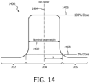
- the coil former is divided into an irradiation zone and at least one reduced radiation zone.
- the pre-amplifier for each of the one or multiple antenna elements is located within the at least one reduced radiation zone.
- the one or multiple antenna elements are located at least partially within the irradiation zone.
- the coil former has a perimeter that forms edges.
- the magnetic resonance antenna is a surface coil. So although the surface coil may not be flat it predominantly has a surface which is bounded by edges. The edges extend about the perimeter of the surface coil.
- the irradiation zone extends continuously from a first edge of the perimeter to a second edge of the perimeter. The first edge and the second edge are opposing or opposite edges.
- the porous material is any one of the following: A foam, expanded polypropylene, Polyutethane foam, Polyimide foam, Polyether ether ketone (PEEK) foam, a corrugated structure, corrugated cardboard, a honeycomb structure, and/or has an attenuation of less than 2% for X-ray radiation between 1.8 mega electron volts and 8 MeV. In another embodiment the porous material has an attenuation of less than 1% for X-ray radiation between 1.8 MeV and 8 MeV.
- the rigid coil former is formed from a solid plastic between 0.2 and 0.8 millimeters thick.
- the biocompatible layer is any one of the following: Ethylene-vinyl acetate, PVC foam, polyurethane (PU) foam, PEEK foam, and Polyvinyl chloride (PVC) foam.
- the medical instrument comprises a LINAC with a X-ray source configured for directing X-ray radiation at a target zone.
- the LINAC is adapted for rotating the X-ray source about a rotational axis.
- the medical instrument further comprises a magnetic resonance imaging system configured for acquiring magnetic resonance data with the magnetic resonance antenna from an imaging zone.
- the target zone is within the imaging zone.
- the X-ray source is adapted for rotating at least partially about the magnet.
- the irradiation zone within a receive coil can have one or more of the following elements:
- the core of the structure is made of rigid, low density foam or material e.g. EPP (Expanded polypropylene).
- EPP Exanded polypropylene
- the material can be either machined or molded to its form. This part forms the basis for the structure in terms of rigidity.
- the density of the material is low, ⁇ 100 kg/m3.
- the outer surface of the structure is made of low density soft foam or material e.g. EVA (Ethylene-vinyl acetate).
- EVA Ethylene-vinyl acetate
- This foam or material is providing the biocompatible surface for the structure. Due to its closed cell structure, it also prevents liquids to ingress the structure.
- the material density is ⁇ 50 kg/ m3.
- Figs. 8, 9 and 10 show several different examples.
- the examples shown in Figs. 8, 9 and 10 show straight cross-sections.
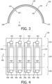
- these straight cross-sections are only exemplary and the coils or antennas may be curved as is illustrated in Figs. 3 , 5, 6 and 7 .
- a split cylindrical magnet is similar to a standard cylindrical magnet, except that the cryostat has been split into two sections to allow access to the iso-plane of the magnet, such magnets may for instance be used to provide a space for X-ray radiation to reach a subject 1536.
- An open magnet has two magnet sections, one above the other with a space in-between that is large enough to receive a subject: the arrangement of the two sections is similar to that of a Helmholtz coil. Open magnets are popular, because the subject is less confined. Inside the cryostat of the cylindrical magnet there is a collection of superconducting coils.
- the magnet 1512 shown in this example is a modifed cylindrical superconducting magnet.
- the magnet 1512 has a cryostat 1514 with superconducting coils within it 1516.
- the magnet is designed such that a X-ray radiation beam 1542 does not intersect the superconducting coils 1516.
- the materials and thicknesses along the beam path 1542 maybe chosen to reduce the attenuation of the X-ray radiation.
- a split or open magnet design may be used instead to eliminate the absorption of radiation by the magnet 1512.
- a subject support 1534 for supporting a subject 1536.
- the subject support 1534 may be positioned by a mechanical positioning system 1537.
- Within the subject 1536 there is a target zone 1538.
- the axis of gantry rotation 1540 is coaxial in this particular example with the cylindrical axis of the magnet 1512.
- the subject support 1534 has been positioned such that the target zone 1538 lies on the axis 1540 of gantry rotation.
- the X-ray source 1508 is shown as generating a radiation beam 1542 which passes through the collimator 1510 and through the target zone 1538. As the radiation source 1508 is rotated about the axis 1540 the target zone 1538 will always be targeted by the radiation beam 1542.
- the computer storage 1552 is shown as containing a treatment plan 1560.
- the computer storage 1552 is further shown as containing a pulse sequence 1562.
- a pulse sequence as used herein is a set of commands used to control various components of the magnetic resonance imaging system 1504 to acquire magnetic resonance data 1564.
- the computer storage 1552 is shown as containing magnetic resonance data 1564 that was acquired using the magnetic resonance imaging system 1504.
Landscapes
- Physics & Mathematics (AREA)
- Health & Medical Sciences (AREA)
- Engineering & Computer Science (AREA)
- Condensed Matter Physics & Semiconductors (AREA)
- General Physics & Mathematics (AREA)
- Nuclear Medicine, Radiotherapy & Molecular Imaging (AREA)
- Biomedical Technology (AREA)
- Pathology (AREA)
- Radiology & Medical Imaging (AREA)
- General Health & Medical Sciences (AREA)
- Theoretical Computer Science (AREA)
- Life Sciences & Earth Sciences (AREA)
- Public Health (AREA)
- Veterinary Medicine (AREA)
- Animal Behavior & Ethology (AREA)
- High Energy & Nuclear Physics (AREA)
- Pulmonology (AREA)
- Magnetic Resonance Imaging Apparatus (AREA)
- Biophysics (AREA)
- Heart & Thoracic Surgery (AREA)
- Medical Informatics (AREA)
- Molecular Biology (AREA)
- Surgery (AREA)
- Radiation-Therapy Devices (AREA)
Claims (12)
- Medizinisches Instrument (1500), das Folgendes umfasst:- einen LINAC (1502) mit einer Röntgenstrahlquelle (1508), die dazu konfiguriert ist, Röntgenstrahlung (1542) auf eine Zielzone (1538) zu richten, wobei der LINAC zur Rotation der Röntgenstrahlquelle um eine Rotationsachse (1540) angepasst ist; und- ein Magnetresonanztomographiesystem (1502), das dazu konfiguriert ist,wobei der Vorverstärker für das Antennenelement innerhalb der mindestens eine reduzierte Strahlungszone liegt, wobei das Antennenelement mindestens teilweise innerhalb der Bestrahlungszone liegt, wobei der Spulenkörper einen Umfang aufweist, wobei sich die Bestrahlungszone durchgehend von einer ersten Kante (208) des Umfangs zu einer zweiten Kante (210) des Umfangs erstreckt, und wobei die erste Kante und die zweite Kante entgegengesetzte Kanten sind.Magnetresonanzdaten (1564) mit einer Magnetresonanzantenne (100) aus einer Bildgebungszone (1532) zu erheben, wobei die Zielzone innerhalb der Bildgebungszone liegt, wobei das Magnetresonanztomographiesystem einen Magnet (1512) umfasst, der dazu konfiguriert ist, ein Magnetfeld innerhalb der Bildgebungszone zu erzeugen, wobei die Röntgenstrahlenquelle dazu angepasst ist, mindestens teilweise, um den Magnet zu rotieren;wobei das Magnetresonanztomographiesystem die Magnetresonanzantenne (100) umfasst, wobei die Magnetresonanzantenne eine Oberflächenspule ist, wobei die Magnetresonanzantenne eine Empfangsspule ist, wobei die Magnetresonanzantenne Folgendes umfasst:- ein Antennenelement (104, 404)- einen Vorverstärker (402) für das Antennenelement; und- einen Spulenkörper (106), der zum Tragen des Antennenelements konfiguriert ist, wobei der Spulenkörper aus einem porösen Material gebildet ist, wobei der Spulenkörper starr ist, wobei der Spulenkörper in eine Bestrahlungszone (204) und mindestens eine Zone (202, 206) mit reduzierter Strahlung geteilt ist, wobei die Bestrahlungszone dazu konfiguriert ist zu ermöglichen, dass Röntgenstrahlung die Magnetresonanzantenne durchdringt, während eine Röntgenstrahlungsdosisabgabe zu der Zielzone minimal gestört wird,
- Medizinisches Instrument nach Anspruch 1, wobei das poröse Material eines der folgenden ist: ein Schaum, expandiertes Polypropylen, Polyurethanschaum, Polyimidschaum, PEEK-Schaum, eine wellige Struktur, Wellpappe und eine Wabenstruktur und/oder eine Dämpfung von weniger als 2 Prozent für Röntgenstrahlung zwischen 1,8 MeV und 8 MeV aufweist.
- Medizinisches Instrument nach Anspruch 1 oder 2, wobei der Querschnitt des Spulenkörpers von der ersten Kante zu der zweiten Kante vorherrschend konvex ist, wenn er aus einer Richtung (302) von dem Spulenkörper zu dem Antennenelement betrachtet wird.
- Medizinisches Instrument nach Anspruch 3, wobei der Querschnitt einer der folgenden ist: ein Halbkreis (300), der gerade Segmente und gerundete Segmente (600), im Allgemeinen flach mit gerundeten Abschnitten nahe der ersten Kante und der zweiten Kante (500) und eine Reihe verbundener gerader Segmente (700) umfasst.
- Medizinisches Instrument nach einem der vorstehenden Ansprüche, wobei der Spulenkörper eine oder mehrere Montagevorrichtungen (1529) zum Anbringen der Magnetresonanzantenne an einem Subjektträger (1534) umfasst.
- Medizinisches Instrument nach einem der vorstehenden Ansprüche, wobei das Antennenelement auf einer biegsamen Leiterplatte gebildet ist, wobei die biegsame Leiterplatte an dem Spulenkörper angebracht ist.
- Medizinisches Instrument nach einem der vorstehenden Ansprüche, das mehrere Antennenelemente umfasst, wobei die mindestens eine reduzierte Strahlungszone zwei oder mehr reduzierte Strahlungszonen sind, wobei die zwei oder mehr reduzierten Strahlungszonen PIN-Dioden (402, 406) zum Steuern des Verstimmens der mehreren Antennenelemente umfassen, wobei die Bestrahlungszone Leiter zum Tragen elektrischer Signale zwischen den zwei oder mehreren reduzierten Strahlungszonen zum Steuern des Umschaltens der PIN-Dioden umfasst.
- Medizinisches Instrument nach einem der vorstehenden Ansprüche, wobei die Magnetresonanzantenne eine erste Oberfläche (108) und eine zweite Oberfläche (102) aufweist, wobei der Spulenkörper zwischen der ersten Oberfläche und dem Antennenelement liegt, wobei das Antennenelement zwischen der zweiten Oberfläche und dem Spulenkörper liegt, wobei die Magnetresonanzantenne ferner Folgendes umfasst:- eine biokompatible (108) Schicht, die die erste Oberfläche bildet, und- eine Außenschicht (102), die die zweite Oberfläche bildet.
- Medizinisches Instrument nach Anspruch 8, wobei die biokompatible Schicht eine der folgenden ist: Ethylenvinylacetat, Polyurethan, Polyamidschaum, PEEK-Schaum und PVC-Schaum, und/oder die Außenschicht eine der folgenden ist: Ethylenvinylacetat, PVC-Schaum und Polyurethan, PEEK-Schaum und PVC-Schaum.
- Medizinisches Instrument nach Anspruch 8 oder 9, wobei die biokompatible Schicht an den Spulenkörper laminiert ist, und/oder wobei die biokompatible Schicht an das Antennenelement laminiert ist.
- Medizinisches Instrument nach einem der vorstehenden Ansprüche, wobei die Dicke des porösen Materials gleichmäßig ist.
- Medizinisches Instrument nach einem der vorstehenden Ansprüche, wobei das medizinische Instrument ferner Folgendes umfasst:- einen Prozessor (1548), der dazu konfiguriert ist, das medizinische Instrument zu steuern:- einen Speicher (1554), die maschinenausführbaren Anweisungen (1580, 1582, 1584, 1586, 1588, 1590) zur Ausführung durch den Prozessor speichert, wobei die Ausführung der maschinenausführbaren Anweisungen den Prozessor dazu veranlasst:- einen Behandlungsplan (1560) zum Bestrahlen der Zielzone zu empfangen (1600);- die Magnetresonanzdaten (1564) unter Verwendung des Magnetresonanztomographiesystems zu erheben (1602);- ein Magnetresonanzbild (1566) aus den Magnetresonanzdaten zu rekonstruieren (1604);- eine Lage (1570) der Zielzone in dem Magnetresonanzbild aufzuzeichnen (1606);- Steuersignale (1572) gemäß der Lage der Zielzone und dem Behandlungsplan zu erzeugen (1608); und- den LINAC zu steuern (1610), um die Zielzone unter Verwendung der Steuersignale zu bestrahlen.
Applications Claiming Priority (2)
| Application Number | Priority Date | Filing Date | Title |
|---|---|---|---|
| EP14183088 | 2014-09-01 | ||
| PCT/EP2015/068258 WO2016034364A1 (en) | 2014-09-01 | 2015-08-07 | Magnetic resonance imaging receive coil with reduced radiation attenuation |
Publications (2)
| Publication Number | Publication Date |
|---|---|
| EP3194997A1 EP3194997A1 (de) | 2017-07-26 |
| EP3194997B1 true EP3194997B1 (de) | 2023-10-11 |
Family
ID=51429150
Family Applications (1)
| Application Number | Title | Priority Date | Filing Date |
|---|---|---|---|
| EP15750366.5A Active EP3194997B1 (de) | 2014-09-01 | 2015-08-07 | Empfangsspule für magnetresonanzbildgebung mit reduzierter strahlungsdämpfung |
Country Status (5)
| Country | Link |
|---|---|
| US (1) | US10718831B2 (de) |
| EP (1) | EP3194997B1 (de) |
| JP (1) | JP6605021B2 (de) |
| CN (1) | CN106922173B (de) |
| WO (1) | WO2016034364A1 (de) |
Families Citing this family (13)
| Publication number | Priority date | Publication date | Assignee | Title |
|---|---|---|---|---|
| DE102015201462B3 (de) * | 2015-01-28 | 2016-05-12 | Siemens Aktiengesellschaft | Hochfrequenz-Spuleneinheit für eine Magnetresonanz-Bildgebung |
| DE102016212421A1 (de) * | 2016-07-07 | 2018-01-11 | Siemens Healthcare Gmbh | Leitungsanordnung zum Einsatz in einer MR-Lokalspule |
| US10391335B2 (en) * | 2017-03-02 | 2019-08-27 | Ingham Institute for Applied Medical Research | Radio-frequency coil for simultaneous imaging and dosimetry on an MRI-linac |
| DE102017206368A1 (de) * | 2017-04-13 | 2018-10-18 | Siemens Aktiengesellschaft | Spulengrundkörper zur Herstellung eines Wirbelstromsensors, einen Wirbelstromsensor sowie eine Vorrichtung, um einen Spulendraht auf den Spulengrundkörper zur Herstellung eines solchen Wirbelstromsensors zu wickeln |
| JP7150415B2 (ja) * | 2017-04-27 | 2022-10-11 | コーニンクレッカ フィリップス エヌ ヴェ | 磁気共鳴イメージング誘導放射線治療用の医療機器 |
| EP3412243A1 (de) * | 2017-06-08 | 2018-12-12 | Servicio Andaluz De Salud | Starre pvc-schaumstoffbahnen zur verwendung in der radiotherapie und/oder diagnosebildgebung |
| EP3428671A1 (de) | 2017-07-11 | 2019-01-16 | Koninklijke Philips N.V. | Hf-versorgungsschaltung für magnetresonanzbildgebung |
| CN109420259A (zh) | 2017-08-24 | 2019-03-05 | 上海联影医疗科技有限公司 | 治疗系统和使用治疗系统的方法 |
| US11883685B2 (en) | 2017-08-24 | 2024-01-30 | Shanghai United Imaging Healthcare Co., Ltd. | Therapeutic system and method |
| US11454685B2 (en) * | 2017-11-27 | 2022-09-27 | Koninklijke Philips N.V. | Mesh networks in wireless MRI RF coil |
| EP3553546A1 (de) * | 2018-04-09 | 2019-10-16 | Koninklijke Philips N.V. | Automatische positionierung von antennenanschlüssen für die kernspintomografie |
| CN109001656B (zh) * | 2018-04-28 | 2019-07-19 | 中国科学院深圳先进技术研究院 | 一种柔性射频接收线圈阵列 |
| CN113253174B (zh) * | 2021-05-13 | 2023-06-16 | 上海联影医疗科技股份有限公司 | 接收天线组件及磁共振装置 |
Family Cites Families (14)
| Publication number | Priority date | Publication date | Assignee | Title |
|---|---|---|---|---|
| EP0990175A4 (de) * | 1995-12-29 | 2000-06-14 | Doty Scient Inc | Transversale folienlitzenspulen niedriger induktanz |
| US7526330B1 (en) * | 2004-07-06 | 2009-04-28 | Pulseteq Limited | Magnetic resonance scanning apparatus |
| US7394254B2 (en) * | 2005-04-27 | 2008-07-01 | The Board Of Trustees Of The Leland Stanford Junior University | Magnetic resonance imaging having radiation compatible radiofrequency coils |
| JP5179820B2 (ja) * | 2006-10-27 | 2013-04-10 | 株式会社東芝 | 高周波コイル装置 |
| US8195272B2 (en) * | 2007-09-24 | 2012-06-05 | MRI Interventions, Inc. | MRI-compatible patches and methods for using the same |
| DE102009023806B4 (de) * | 2008-07-09 | 2011-04-28 | Siemens Aktiengesellschaft | Kombinierte PET-MR-Einrichtung, Bauteil und Lokalspule |
| DE102008046974B4 (de) * | 2008-09-12 | 2013-12-19 | Siemens Aktiengesellschaft | Lokalspuleneinrichtung für Magnetresonanz-Tomographie-Vorrichtung |
| AU2010273298B2 (en) * | 2009-07-15 | 2014-10-23 | Viewray Technologies, Inc. | Method and apparatus for shielding a linear accelerator and a magnetic resonance imaging device from each other |
| DE102009043446B4 (de) * | 2009-09-29 | 2013-08-01 | Siemens Aktiengesellschaft | Magnetresonanzanlage mit einem in seiner Geometrie veränderbaren Lokalspulenarray |
| US8604789B2 (en) * | 2010-04-30 | 2013-12-10 | Imris Inc. | RF coil assembly for use in magnetic resonance imaging |
| EP2638409B1 (de) * | 2010-11-09 | 2020-01-08 | Koninklijke Philips N.V. | Magnetresonanzbildgebung und stralentherapiegerät mit mindestens zwei sende- und empfangskanälen |
| US9081067B2 (en) * | 2011-05-09 | 2015-07-14 | Imris Inc. | Phased array MR RF coil which is not visible in X-ray image |
| US8797030B2 (en) * | 2011-07-28 | 2014-08-05 | General Electric Company | Magnetic resonance radio-frequency coil and method of manufacturing |
| RU2631910C2 (ru) * | 2012-09-18 | 2017-09-28 | Конинклейке Филипс Н.В. | Линейный ускоритель, направляемый магнитным резонансом |
-
2015
- 2015-08-07 US US15/505,259 patent/US10718831B2/en active Active
- 2015-08-07 WO PCT/EP2015/068258 patent/WO2016034364A1/en not_active Ceased
- 2015-08-07 JP JP2017511187A patent/JP6605021B2/ja active Active
- 2015-08-07 CN CN201580058853.3A patent/CN106922173B/zh active Active
- 2015-08-07 EP EP15750366.5A patent/EP3194997B1/de active Active
Also Published As
| Publication number | Publication date |
|---|---|
| US10718831B2 (en) | 2020-07-21 |
| JP6605021B2 (ja) | 2019-11-13 |
| EP3194997A1 (de) | 2017-07-26 |
| CN106922173A (zh) | 2017-07-04 |
| WO2016034364A1 (en) | 2016-03-10 |
| US20170252578A1 (en) | 2017-09-07 |
| JP2017529147A (ja) | 2017-10-05 |
| CN106922173B (zh) | 2021-03-23 |
Similar Documents
| Publication | Publication Date | Title |
|---|---|---|
| EP3194997B1 (de) | Empfangsspule für magnetresonanzbildgebung mit reduzierter strahlungsdämpfung | |
| US10307616B2 (en) | Medical apparatus with a radiation therapy device and a radiation detection system | |
| US10022104B2 (en) | Markers, phantoms and associated methods for calibrating imaging systems | |
| US9504851B2 (en) | Magnetic resonance imaging of bone tissue | |
| EP2638409B1 (de) | Magnetresonanzbildgebung und stralentherapiegerät mit mindestens zwei sende- und empfangskanälen | |
| US9608395B2 (en) | Slip ring assembly | |
| EP3066488B1 (de) | Medizinische vorrichtung für röntgentherapie und ultraschallerwärmung | |
| JP7150415B2 (ja) | 磁気共鳴イメージング誘導放射線治療用の医療機器 | |
| Kron et al. | Magnetic resonance imaging for adaptive cobalt tomotherapy: A proposal | |
| JP6965261B2 (ja) | Mri装置及びmrガイド放射線治療システムに対するmr可視マーカ | |
| Baldock | Medical Imaging–X-rays |
Legal Events
| Date | Code | Title | Description |
|---|---|---|---|
| STAA | Information on the status of an ep patent application or granted ep patent |
Free format text: STATUS: THE INTERNATIONAL PUBLICATION HAS BEEN MADE |
|
| PUAI | Public reference made under article 153(3) epc to a published international application that has entered the european phase |
Free format text: ORIGINAL CODE: 0009012 |
|
| STAA | Information on the status of an ep patent application or granted ep patent |
Free format text: STATUS: REQUEST FOR EXAMINATION WAS MADE |
|
| 17P | Request for examination filed |
Effective date: 20170403 |
|
| AK | Designated contracting states |
Kind code of ref document: A1 Designated state(s): AL AT BE BG CH CY CZ DE DK EE ES FI FR GB GR HR HU IE IS IT LI LT LU LV MC MK MT NL NO PL PT RO RS SE SI SK SM TR |
|
| AX | Request for extension of the european patent |
Extension state: BA ME |
|
| DAV | Request for validation of the european patent (deleted) | ||
| DAX | Request for extension of the european patent (deleted) | ||
| RAP1 | Party data changed (applicant data changed or rights of an application transferred) |
Owner name: KONINKLIJKE PHILIPS N.V. |
|
| STAA | Information on the status of an ep patent application or granted ep patent |
Free format text: STATUS: EXAMINATION IS IN PROGRESS |
|
| 17Q | First examination report despatched |
Effective date: 20210409 |
|
| GRAP | Despatch of communication of intention to grant a patent |
Free format text: ORIGINAL CODE: EPIDOSNIGR1 |
|
| STAA | Information on the status of an ep patent application or granted ep patent |
Free format text: STATUS: GRANT OF PATENT IS INTENDED |
|
| INTG | Intention to grant announced |
Effective date: 20230420 |
|
| GRAS | Grant fee paid |
Free format text: ORIGINAL CODE: EPIDOSNIGR3 |
|
| GRAA | (expected) grant |
Free format text: ORIGINAL CODE: 0009210 |
|
| STAA | Information on the status of an ep patent application or granted ep patent |
Free format text: STATUS: THE PATENT HAS BEEN GRANTED |
|
| AK | Designated contracting states |
Kind code of ref document: B1 Designated state(s): AL AT BE BG CH CY CZ DE DK EE ES FI FR GB GR HR HU IE IS IT LI LT LU LV MC MK MT NL NO PL PT RO RS SE SI SK SM TR |
|
| REG | Reference to a national code |
Ref country code: GB Ref legal event code: FG4D |
|
| REG | Reference to a national code |
Ref country code: CH Ref legal event code: EP |
|
| REG | Reference to a national code |
Ref country code: DE Ref legal event code: R096 Ref document number: 602015086058 Country of ref document: DE |
|
| REG | Reference to a national code |
Ref country code: IE Ref legal event code: FG4D |
|
| REG | Reference to a national code |
Ref country code: DE Ref legal event code: R084 Ref document number: 602015086058 Country of ref document: DE |
|
| REG | Reference to a national code |
Ref country code: LT Ref legal event code: MG9D |
|
| REG | Reference to a national code |
Ref country code: NL Ref legal event code: MP Effective date: 20231011 |
|
| REG | Reference to a national code |
Ref country code: AT Ref legal event code: MK05 Ref document number: 1620727 Country of ref document: AT Kind code of ref document: T Effective date: 20231011 |
|
| PG25 | Lapsed in a contracting state [announced via postgrant information from national office to epo] |
Ref country code: NL Free format text: LAPSE BECAUSE OF FAILURE TO SUBMIT A TRANSLATION OF THE DESCRIPTION OR TO PAY THE FEE WITHIN THE PRESCRIBED TIME-LIMIT Effective date: 20231011 |
|
| PG25 | Lapsed in a contracting state [announced via postgrant information from national office to epo] |
Ref country code: GR Free format text: LAPSE BECAUSE OF FAILURE TO SUBMIT A TRANSLATION OF THE DESCRIPTION OR TO PAY THE FEE WITHIN THE PRESCRIBED TIME-LIMIT Effective date: 20240112 |
|
| PG25 | Lapsed in a contracting state [announced via postgrant information from national office to epo] |
Ref country code: IS Free format text: LAPSE BECAUSE OF FAILURE TO SUBMIT A TRANSLATION OF THE DESCRIPTION OR TO PAY THE FEE WITHIN THE PRESCRIBED TIME-LIMIT Effective date: 20240211 |
|
| REG | Reference to a national code |
Ref country code: GB Ref legal event code: 746 Effective date: 20240314 |
|
| PG25 | Lapsed in a contracting state [announced via postgrant information from national office to epo] |
Ref country code: LT Free format text: LAPSE BECAUSE OF FAILURE TO SUBMIT A TRANSLATION OF THE DESCRIPTION OR TO PAY THE FEE WITHIN THE PRESCRIBED TIME-LIMIT Effective date: 20231011 |
|
| PG25 | Lapsed in a contracting state [announced via postgrant information from national office to epo] |
Ref country code: AT Free format text: LAPSE BECAUSE OF FAILURE TO SUBMIT A TRANSLATION OF THE DESCRIPTION OR TO PAY THE FEE WITHIN THE PRESCRIBED TIME-LIMIT Effective date: 20231011 |
|
| PG25 | Lapsed in a contracting state [announced via postgrant information from national office to epo] |
Ref country code: ES Free format text: LAPSE BECAUSE OF FAILURE TO SUBMIT A TRANSLATION OF THE DESCRIPTION OR TO PAY THE FEE WITHIN THE PRESCRIBED TIME-LIMIT Effective date: 20231011 |
|
| PG25 | Lapsed in a contracting state [announced via postgrant information from national office to epo] |
Ref country code: LT Free format text: LAPSE BECAUSE OF FAILURE TO SUBMIT A TRANSLATION OF THE DESCRIPTION OR TO PAY THE FEE WITHIN THE PRESCRIBED TIME-LIMIT Effective date: 20231011 Ref country code: IS Free format text: LAPSE BECAUSE OF FAILURE TO SUBMIT A TRANSLATION OF THE DESCRIPTION OR TO PAY THE FEE WITHIN THE PRESCRIBED TIME-LIMIT Effective date: 20240211 Ref country code: GR Free format text: LAPSE BECAUSE OF FAILURE TO SUBMIT A TRANSLATION OF THE DESCRIPTION OR TO PAY THE FEE WITHIN THE PRESCRIBED TIME-LIMIT Effective date: 20240112 Ref country code: ES Free format text: LAPSE BECAUSE OF FAILURE TO SUBMIT A TRANSLATION OF THE DESCRIPTION OR TO PAY THE FEE WITHIN THE PRESCRIBED TIME-LIMIT Effective date: 20231011 Ref country code: BG Free format text: LAPSE BECAUSE OF FAILURE TO SUBMIT A TRANSLATION OF THE DESCRIPTION OR TO PAY THE FEE WITHIN THE PRESCRIBED TIME-LIMIT Effective date: 20240111 Ref country code: AT Free format text: LAPSE BECAUSE OF FAILURE TO SUBMIT A TRANSLATION OF THE DESCRIPTION OR TO PAY THE FEE WITHIN THE PRESCRIBED TIME-LIMIT Effective date: 20231011 Ref country code: PT Free format text: LAPSE BECAUSE OF FAILURE TO SUBMIT A TRANSLATION OF THE DESCRIPTION OR TO PAY THE FEE WITHIN THE PRESCRIBED TIME-LIMIT Effective date: 20240212 |
|
| PG25 | Lapsed in a contracting state [announced via postgrant information from national office to epo] |
Ref country code: SE Free format text: LAPSE BECAUSE OF FAILURE TO SUBMIT A TRANSLATION OF THE DESCRIPTION OR TO PAY THE FEE WITHIN THE PRESCRIBED TIME-LIMIT Effective date: 20231011 Ref country code: RS Free format text: LAPSE BECAUSE OF FAILURE TO SUBMIT A TRANSLATION OF THE DESCRIPTION OR TO PAY THE FEE WITHIN THE PRESCRIBED TIME-LIMIT Effective date: 20231011 Ref country code: PL Free format text: LAPSE BECAUSE OF FAILURE TO SUBMIT A TRANSLATION OF THE DESCRIPTION OR TO PAY THE FEE WITHIN THE PRESCRIBED TIME-LIMIT Effective date: 20231011 Ref country code: NO Free format text: LAPSE BECAUSE OF FAILURE TO SUBMIT A TRANSLATION OF THE DESCRIPTION OR TO PAY THE FEE WITHIN THE PRESCRIBED TIME-LIMIT Effective date: 20240111 Ref country code: LV Free format text: LAPSE BECAUSE OF FAILURE TO SUBMIT A TRANSLATION OF THE DESCRIPTION OR TO PAY THE FEE WITHIN THE PRESCRIBED TIME-LIMIT Effective date: 20231011 Ref country code: HR Free format text: LAPSE BECAUSE OF FAILURE TO SUBMIT A TRANSLATION OF THE DESCRIPTION OR TO PAY THE FEE WITHIN THE PRESCRIBED TIME-LIMIT Effective date: 20231011 |
|
| PG25 | Lapsed in a contracting state [announced via postgrant information from national office to epo] |
Ref country code: DK Free format text: LAPSE BECAUSE OF FAILURE TO SUBMIT A TRANSLATION OF THE DESCRIPTION OR TO PAY THE FEE WITHIN THE PRESCRIBED TIME-LIMIT Effective date: 20231011 |
|
| REG | Reference to a national code |
Ref country code: DE Ref legal event code: R097 Ref document number: 602015086058 Country of ref document: DE |
|
| PG25 | Lapsed in a contracting state [announced via postgrant information from national office to epo] |
Ref country code: CZ Free format text: LAPSE BECAUSE OF FAILURE TO SUBMIT A TRANSLATION OF THE DESCRIPTION OR TO PAY THE FEE WITHIN THE PRESCRIBED TIME-LIMIT Effective date: 20231011 |
|
| PG25 | Lapsed in a contracting state [announced via postgrant information from national office to epo] |
Ref country code: SK Free format text: LAPSE BECAUSE OF FAILURE TO SUBMIT A TRANSLATION OF THE DESCRIPTION OR TO PAY THE FEE WITHIN THE PRESCRIBED TIME-LIMIT Effective date: 20231011 |
|
| PG25 | Lapsed in a contracting state [announced via postgrant information from national office to epo] |
Ref country code: SM Free format text: LAPSE BECAUSE OF FAILURE TO SUBMIT A TRANSLATION OF THE DESCRIPTION OR TO PAY THE FEE WITHIN THE PRESCRIBED TIME-LIMIT Effective date: 20231011 Ref country code: SK Free format text: LAPSE BECAUSE OF FAILURE TO SUBMIT A TRANSLATION OF THE DESCRIPTION OR TO PAY THE FEE WITHIN THE PRESCRIBED TIME-LIMIT Effective date: 20231011 Ref country code: RO Free format text: LAPSE BECAUSE OF FAILURE TO SUBMIT A TRANSLATION OF THE DESCRIPTION OR TO PAY THE FEE WITHIN THE PRESCRIBED TIME-LIMIT Effective date: 20231011 Ref country code: IT Free format text: LAPSE BECAUSE OF FAILURE TO SUBMIT A TRANSLATION OF THE DESCRIPTION OR TO PAY THE FEE WITHIN THE PRESCRIBED TIME-LIMIT Effective date: 20231011 Ref country code: EE Free format text: LAPSE BECAUSE OF FAILURE TO SUBMIT A TRANSLATION OF THE DESCRIPTION OR TO PAY THE FEE WITHIN THE PRESCRIBED TIME-LIMIT Effective date: 20231011 Ref country code: DK Free format text: LAPSE BECAUSE OF FAILURE TO SUBMIT A TRANSLATION OF THE DESCRIPTION OR TO PAY THE FEE WITHIN THE PRESCRIBED TIME-LIMIT Effective date: 20231011 Ref country code: CZ Free format text: LAPSE BECAUSE OF FAILURE TO SUBMIT A TRANSLATION OF THE DESCRIPTION OR TO PAY THE FEE WITHIN THE PRESCRIBED TIME-LIMIT Effective date: 20231011 |
|
| PLBE | No opposition filed within time limit |
Free format text: ORIGINAL CODE: 0009261 |
|
| STAA | Information on the status of an ep patent application or granted ep patent |
Free format text: STATUS: NO OPPOSITION FILED WITHIN TIME LIMIT |
|
| 26N | No opposition filed |
Effective date: 20240712 |
|
| PG25 | Lapsed in a contracting state [announced via postgrant information from national office to epo] |
Ref country code: SI Free format text: LAPSE BECAUSE OF FAILURE TO SUBMIT A TRANSLATION OF THE DESCRIPTION OR TO PAY THE FEE WITHIN THE PRESCRIBED TIME-LIMIT Effective date: 20231011 |
|
| PG25 | Lapsed in a contracting state [announced via postgrant information from national office to epo] |
Ref country code: SI Free format text: LAPSE BECAUSE OF FAILURE TO SUBMIT A TRANSLATION OF THE DESCRIPTION OR TO PAY THE FEE WITHIN THE PRESCRIBED TIME-LIMIT Effective date: 20231011 |
|
| REG | Reference to a national code |
Ref country code: CH Ref legal event code: PL |
|
| PG25 | Lapsed in a contracting state [announced via postgrant information from national office to epo] |
Ref country code: LU Free format text: LAPSE BECAUSE OF NON-PAYMENT OF DUE FEES Effective date: 20240807 |
|
| PG25 | Lapsed in a contracting state [announced via postgrant information from national office to epo] |
Ref country code: CH Free format text: LAPSE BECAUSE OF NON-PAYMENT OF DUE FEES Effective date: 20240831 Ref country code: MC Free format text: LAPSE BECAUSE OF FAILURE TO SUBMIT A TRANSLATION OF THE DESCRIPTION OR TO PAY THE FEE WITHIN THE PRESCRIBED TIME-LIMIT Effective date: 20231011 |
|
| REG | Reference to a national code |
Ref country code: BE Ref legal event code: MM Effective date: 20240831 |
|
| PG25 | Lapsed in a contracting state [announced via postgrant information from national office to epo] |
Ref country code: BE Free format text: LAPSE BECAUSE OF NON-PAYMENT OF DUE FEES Effective date: 20240831 |
|
| PG25 | Lapsed in a contracting state [announced via postgrant information from national office to epo] |
Ref country code: IE Free format text: LAPSE BECAUSE OF NON-PAYMENT OF DUE FEES Effective date: 20240807 |
|
| PG25 | Lapsed in a contracting state [announced via postgrant information from national office to epo] |
Ref country code: FI Free format text: LAPSE BECAUSE OF FAILURE TO SUBMIT A TRANSLATION OF THE DESCRIPTION OR TO PAY THE FEE WITHIN THE PRESCRIBED TIME-LIMIT Effective date: 20231011 |
|
| PGFP | Annual fee paid to national office [announced via postgrant information from national office to epo] |
Ref country code: DE Payment date: 20250827 Year of fee payment: 11 |
|
| PGFP | Annual fee paid to national office [announced via postgrant information from national office to epo] |
Ref country code: GB Payment date: 20250826 Year of fee payment: 11 |
|
| PGFP | Annual fee paid to national office [announced via postgrant information from national office to epo] |
Ref country code: FR Payment date: 20250825 Year of fee payment: 11 |
|
| PG25 | Lapsed in a contracting state [announced via postgrant information from national office to epo] |
Ref country code: CY Free format text: LAPSE BECAUSE OF FAILURE TO SUBMIT A TRANSLATION OF THE DESCRIPTION OR TO PAY THE FEE WITHIN THE PRESCRIBED TIME-LIMIT; INVALID AB INITIO Effective date: 20150807 |
|
| PG25 | Lapsed in a contracting state [announced via postgrant information from national office to epo] |
Ref country code: HU Free format text: LAPSE BECAUSE OF FAILURE TO SUBMIT A TRANSLATION OF THE DESCRIPTION OR TO PAY THE FEE WITHIN THE PRESCRIBED TIME-LIMIT; INVALID AB INITIO Effective date: 20150807 |