EP3196122A1 - Emballage basse pression pour avion - Google Patents
Emballage basse pression pour avion Download PDFInfo
- Publication number
- EP3196122A1 EP3196122A1 EP17151193.4A EP17151193A EP3196122A1 EP 3196122 A1 EP3196122 A1 EP 3196122A1 EP 17151193 A EP17151193 A EP 17151193A EP 3196122 A1 EP3196122 A1 EP 3196122A1
- Authority
- EP
- European Patent Office
- Prior art keywords
- fluid
- aperture
- tubular member
- duct
- downstream
- Prior art date
- Legal status (The legal status is an assumption and is not a legal conclusion. Google has not performed a legal analysis and makes no representation as to the accuracy of the status listed.)
- Granted
Links
Images

Classifications
-
- F—MECHANICAL ENGINEERING; LIGHTING; HEATING; WEAPONS; BLASTING
- F25—REFRIGERATION OR COOLING; COMBINED HEATING AND REFRIGERATION SYSTEMS; HEAT PUMP SYSTEMS; MANUFACTURE OR STORAGE OF ICE; LIQUEFACTION SOLIDIFICATION OF GASES
- F25B—REFRIGERATION MACHINES, PLANTS OR SYSTEMS; COMBINED HEATING AND REFRIGERATION SYSTEMS; HEAT PUMP SYSTEMS
- F25B41/00—Fluid-circulation arrangements
- F25B41/20—Disposition of valves, e.g. of on-off valves or flow control valves
-
- B—PERFORMING OPERATIONS; TRANSPORTING
- B01—PHYSICAL OR CHEMICAL PROCESSES OR APPARATUS IN GENERAL
- B01D—SEPARATION
- B01D45/00—Separating dispersed particles from gases or vapours by gravity, inertia, or centrifugal forces
- B01D45/12—Separating dispersed particles from gases or vapours by gravity, inertia, or centrifugal forces by centrifugal forces
- B01D45/16—Separating dispersed particles from gases or vapours by gravity, inertia, or centrifugal forces by centrifugal forces generated by the winding course of the gas stream, the centrifugal forces being generated solely or partly by mechanical means, e.g. fixed swirl vanes
-
- B—PERFORMING OPERATIONS; TRANSPORTING
- B01—PHYSICAL OR CHEMICAL PROCESSES OR APPARATUS IN GENERAL
- B01D—SEPARATION
- B01D53/00—Separation of gases or vapours; Recovering vapours of volatile solvents from gases; Chemical or biological purification of waste gases, e.g. engine exhaust gases, smoke, fumes, flue gases, aerosols
- B01D53/26—Drying gases or vapours
- B01D53/265—Drying gases or vapours by refrigeration (condensation)
-
- B—PERFORMING OPERATIONS; TRANSPORTING
- B04—CENTRIFUGAL APPARATUS OR MACHINES FOR CARRYING-OUT PHYSICAL OR CHEMICAL PROCESSES
- B04C—APPARATUS USING FREE VORTEX FLOW, e.g. CYCLONES
- B04C3/00—Apparatus in which the axial direction of the vortex flow following a screw-thread type line remains unchanged ; Devices in which one of the two discharge ducts returns centrally through the vortex chamber, a reverse-flow vortex being prevented by bulkheads in the central discharge duct
- B04C3/06—Construction of inlets or outlets to the vortex chamber
-
- B—PERFORMING OPERATIONS; TRANSPORTING
- B64—AIRCRAFT; AVIATION; COSMONAUTICS
- B64D—EQUIPMENT FOR FITTING IN OR TO AIRCRAFT; FLIGHT SUITS; PARACHUTES; ARRANGEMENT OR MOUNTING OF POWER PLANTS OR PROPULSION TRANSMISSIONS IN AIRCRAFT
- B64D13/00—Arrangements or adaptations of air-treatment apparatus for aircraft crew or passengers, or freight space
- B64D13/02—Arrangements or adaptations of air-treatment apparatus for aircraft crew or passengers, or freight space the air being pressurised
-
- B—PERFORMING OPERATIONS; TRANSPORTING
- B64—AIRCRAFT; AVIATION; COSMONAUTICS
- B64D—EQUIPMENT FOR FITTING IN OR TO AIRCRAFT; FLIGHT SUITS; PARACHUTES; ARRANGEMENT OR MOUNTING OF POWER PLANTS OR PROPULSION TRANSMISSIONS IN AIRCRAFT
- B64D13/00—Arrangements or adaptations of air-treatment apparatus for aircraft crew or passengers, or freight space
- B64D13/06—Arrangements or adaptations of air-treatment apparatus for aircraft crew or passengers, or freight space the air being conditioned
- B64D13/08—Arrangements or adaptations of air-treatment apparatus for aircraft crew or passengers, or freight space the air being conditioned the air being heated or cooled
-
- F—MECHANICAL ENGINEERING; LIGHTING; HEATING; WEAPONS; BLASTING
- F25—REFRIGERATION OR COOLING; COMBINED HEATING AND REFRIGERATION SYSTEMS; HEAT PUMP SYSTEMS; MANUFACTURE OR STORAGE OF ICE; LIQUEFACTION SOLIDIFICATION OF GASES
- F25B—REFRIGERATION MACHINES, PLANTS OR SYSTEMS; COMBINED HEATING AND REFRIGERATION SYSTEMS; HEAT PUMP SYSTEMS
- F25B49/00—Arrangement or mounting of control or safety devices
- F25B49/02—Arrangement or mounting of control or safety devices for compression type machines, plants or systems
-
- F—MECHANICAL ENGINEERING; LIGHTING; HEATING; WEAPONS; BLASTING
- F25—REFRIGERATION OR COOLING; COMBINED HEATING AND REFRIGERATION SYSTEMS; HEAT PUMP SYSTEMS; MANUFACTURE OR STORAGE OF ICE; LIQUEFACTION SOLIDIFICATION OF GASES
- F25B—REFRIGERATION MACHINES, PLANTS OR SYSTEMS; COMBINED HEATING AND REFRIGERATION SYSTEMS; HEAT PUMP SYSTEMS
- F25B9/00—Compression machines, plants or systems, in which the refrigerant is air or other gas of low boiling point
- F25B9/002—Compression machines, plants or systems, in which the refrigerant is air or other gas of low boiling point characterised by the refrigerant
- F25B9/004—Compression machines, plants or systems, in which the refrigerant is air or other gas of low boiling point characterised by the refrigerant the refrigerant being air
-
- F—MECHANICAL ENGINEERING; LIGHTING; HEATING; WEAPONS; BLASTING
- F25—REFRIGERATION OR COOLING; COMBINED HEATING AND REFRIGERATION SYSTEMS; HEAT PUMP SYSTEMS; MANUFACTURE OR STORAGE OF ICE; LIQUEFACTION SOLIDIFICATION OF GASES
- F25B—REFRIGERATION MACHINES, PLANTS OR SYSTEMS; COMBINED HEATING AND REFRIGERATION SYSTEMS; HEAT PUMP SYSTEMS
- F25B9/00—Compression machines, plants or systems, in which the refrigerant is air or other gas of low boiling point
- F25B9/06—Compression machines, plants or systems, in which the refrigerant is air or other gas of low boiling point using expanders
-
- B—PERFORMING OPERATIONS; TRANSPORTING
- B04—CENTRIFUGAL APPARATUS OR MACHINES FOR CARRYING-OUT PHYSICAL OR CHEMICAL PROCESSES
- B04C—APPARATUS USING FREE VORTEX FLOW, e.g. CYCLONES
- B04C3/00—Apparatus in which the axial direction of the vortex flow following a screw-thread type line remains unchanged ; Devices in which one of the two discharge ducts returns centrally through the vortex chamber, a reverse-flow vortex being prevented by bulkheads in the central discharge duct
- B04C2003/006—Construction of elements by which the vortex flow is generated or degenerated
-
- B—PERFORMING OPERATIONS; TRANSPORTING
- B64—AIRCRAFT; AVIATION; COSMONAUTICS
- B64D—EQUIPMENT FOR FITTING IN OR TO AIRCRAFT; FLIGHT SUITS; PARACHUTES; ARRANGEMENT OR MOUNTING OF POWER PLANTS OR PROPULSION TRANSMISSIONS IN AIRCRAFT
- B64D13/00—Arrangements or adaptations of air-treatment apparatus for aircraft crew or passengers, or freight space
- B64D13/06—Arrangements or adaptations of air-treatment apparatus for aircraft crew or passengers, or freight space the air being conditioned
- B64D2013/0603—Environmental Control Systems
- B64D2013/0618—Environmental Control Systems with arrangements for reducing or managing bleed air, using another air source, e.g. ram air
-
- B—PERFORMING OPERATIONS; TRANSPORTING
- B64—AIRCRAFT; AVIATION; COSMONAUTICS
- B64D—EQUIPMENT FOR FITTING IN OR TO AIRCRAFT; FLIGHT SUITS; PARACHUTES; ARRANGEMENT OR MOUNTING OF POWER PLANTS OR PROPULSION TRANSMISSIONS IN AIRCRAFT
- B64D13/00—Arrangements or adaptations of air-treatment apparatus for aircraft crew or passengers, or freight space
- B64D13/06—Arrangements or adaptations of air-treatment apparatus for aircraft crew or passengers, or freight space the air being conditioned
- B64D2013/0603—Environmental Control Systems
- B64D2013/0648—Environmental Control Systems with energy recovery means, e.g. using turbines
-
- B—PERFORMING OPERATIONS; TRANSPORTING
- B64—AIRCRAFT; AVIATION; COSMONAUTICS
- B64D—EQUIPMENT FOR FITTING IN OR TO AIRCRAFT; FLIGHT SUITS; PARACHUTES; ARRANGEMENT OR MOUNTING OF POWER PLANTS OR PROPULSION TRANSMISSIONS IN AIRCRAFT
- B64D13/00—Arrangements or adaptations of air-treatment apparatus for aircraft crew or passengers, or freight space
- B64D13/06—Arrangements or adaptations of air-treatment apparatus for aircraft crew or passengers, or freight space the air being conditioned
- B64D2013/0603—Environmental Control Systems
- B64D2013/0688—Environmental Control Systems with means for recirculating cabin air
-
- F—MECHANICAL ENGINEERING; LIGHTING; HEATING; WEAPONS; BLASTING
- F25—REFRIGERATION OR COOLING; COMBINED HEATING AND REFRIGERATION SYSTEMS; HEAT PUMP SYSTEMS; MANUFACTURE OR STORAGE OF ICE; LIQUEFACTION SOLIDIFICATION OF GASES
- F25B—REFRIGERATION MACHINES, PLANTS OR SYSTEMS; COMBINED HEATING AND REFRIGERATION SYSTEMS; HEAT PUMP SYSTEMS
- F25B2600/00—Control issues
- F25B2600/25—Control of valves
- F25B2600/2507—Flow-diverting valves
-
- Y—GENERAL TAGGING OF NEW TECHNOLOGICAL DEVELOPMENTS; GENERAL TAGGING OF CROSS-SECTIONAL TECHNOLOGIES SPANNING OVER SEVERAL SECTIONS OF THE IPC; TECHNICAL SUBJECTS COVERED BY FORMER USPC CROSS-REFERENCE ART COLLECTIONS [XRACs] AND DIGESTS
- Y02—TECHNOLOGIES OR APPLICATIONS FOR MITIGATION OR ADAPTATION AGAINST CLIMATE CHANGE
- Y02T—CLIMATE CHANGE MITIGATION TECHNOLOGIES RELATED TO TRANSPORTATION
- Y02T50/00—Aeronautics or air transport
- Y02T50/50—On board measures aiming to increase energy efficiency
Definitions
- the subject matter disclosed herein relates to aircraft environmental control systems (ECS) and, more particularly, to an economical (ECO) low pressure ECS.
- the environmental control system (ECS) of an aircraft provides air supply, thermal control and cabin pressurization for the crew and passengers.
- Avionics cooling, smoke detection and fire suppression are also commonly considered part of an aircraft's environmental control system.
- a duct includes a tubular member and a tributary tubular member fluidly coupled to the tubular member.
- the tributary tubular member includes a first torus sector defining a first aperture through which the tubular member extends and a second torus sector defining a second aperture to which the tubular member extends.
- the second torus sector is disposed within the first torus sector to define a sectioned toroidal annulus about the first and second apertures and between an exterior surface of the second torus sector and an interior surface of the first torus sector.
- the tubular member narrows at a border between the inlet and central portions.
- the first aperture has a continuous taper and the second aperture has a non-continuous taper.
- the sectioned toroidal annulus has an increasing thickness.
- the duct further includes an annular fluid collector receptive of fluid from the sectioned toroidal annulus.
- a fluid extractor assembly includes a main duct having an upstream section, a downstream section oriented transversely with respect to the upstream section and an elbow interposed between the upstream and downstream sections.
- the main duct includes first and second torus sectors at the elbow to respectively define first and second apertures with the second torus sector disposed within the first torus sector to form a central flow path and a condensate collection gap about the central flow path.
- the fluid extractor assembly further includes an upstream duct disposed in parallel with the downstream section and to extend through the first aperture and to the second aperture for fluid communication with the downstream section.
- the upstream and downstream sections are perpendicular.
- the downstream section includes a downstream elbow.
- the first aperture is continuously tapered and the second aperture is non-continuously tapered.
- the condensate collection gap has a cross-sectional area that increases in a downstream direction.
- the fluid extractor assembly further includes fluid extractor swirl vanes in the upstream section to drive fluid of a fluid flow proceeding into the central flow path into the condensate collection gap and a fluid extractor receptive of the fluid driven into the condensate collection gap.
- the fluid extractor is operably disposed about the downstream section.
- the fluid extractor includes an annular body defining a condensate settling chamber.
- a low pressure pack includes ram and bleed air circuits, a condenser, an air cycle machine (ACM), a fluid extractor assembly configured to extract a first fluid from a second fluid and to direct the second fluid from the condenser to the ACM, a duct fluidly coupled with the fluid extractor assembly to direct a third fluid along a substantially straight line into and through the fluid extractor assembly to the ACM and a controllable valve system.
- ACM air cycle machine
- the controllable valve system is configured to block the third fluid within the duct and direct the second fluid from the ram air circuit to the ACM through the condenser and through the fluid extractor assembly for first fluid extraction or to block the second fluid upstream from the condenser and direct the third fluid through the fluid extractor assembly to the ACM.
- the first fluid includes water
- the second fluid includes ram air
- the third fluid includes cabin air
- the ram air circuit includes a two-pass heat exchanger.
- the ACM includes a turbine and a compressor.
- the fluid extractor assembly includes a first torus sector defining a first aperture, a second torus sector a second aperture, the second torus sector being disposed within the first torus sector to form a central flow path and a condensate collection gap about the central flow path, fluid extractor swirl vanes to drive the first fluid into the condensate collection gap and a fluid extractor receptive of the first fluid from the condensate collection gap.
- the duct is fluidly coupled with the fluid extractor assembly downstream from the fluid extractor swirl vanes.
- controllable valve system includes a heat exchanger diverter valve operably disposed upstream from the condenser and a turbine control valve operably disposed within the duct.
- a power turbine control valve (TCV) and a water extractor (WE) are combined and consolidated into a single element for an aircraft.
- TCV power turbine control valve
- WE water extractor
- an additional connection to the cabin is provided to the power turbine with limited or no bends in the connection.
- the connection is also downstream from water collection swirl vanes such that water extractor efficiency is maintained.
- the power turbine can thus act as a power turbine in flight and as a cooling turbine in ground operations.
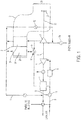
- a low pressure pack 1 is provided for use with an aircraft.
- the low pressure pack 1 includes a ram air circuit 2, which itself includes a two-pass heat exchanger 3, a condenser 4, an air cycle machine (ACM) 5, which includes a turbine 6 and a compressor 7, a fluid extractor assembly 8, which is configured to extract a first fluid (e.g., water) from a second fluid (e.g., engine bleed air) and to direct the second fluid from the condenser 4 to the turbine 6 of the ACM 5, a duct 9 and a controllable valve system 10.
- the duct 9 is fluidly coupled with the fluid extractor assembly 8 to direct a third fluid (e.g., cabin air) from the cabin along a substantially straight line into and through the fluid extractor assembly 8 to the turbine 6 of the ACM 5.
- a third fluid e.g., cabin air
- the controllable valve system 10 includes a heat exchanger diverter valve 11, which is operably disposed upstream from the condenser 4 and a turbine control valve 12, which is operably disposed within the duct 9.
- the controllable valve system 10 may thus be configured to assume a first state in which the heat exchanger diverter valve 11 is open and the turbine control valve 12 is closed whereby the closed turbine control valve 12 blocks the third fluid within the duct 9 and the heat exchanger diverter valve 11 is opened to permit the second fluid to be directed from the ram air circuit 2 to the turbine 6 of the ACM 5 through the condenser 4 and through the fluid extractor assembly 8 for first fluid extraction within the fluid extractor assembly 8 (see FIG. 3 ).
- controllable valve system 10 may be configured to assume a second state in which the heat exchanger diverter valve 11 is closed and blocks the second fluid upstream from the condenser 4 and the turbine control valve 12 is open to permit the third fluid to be directed through the fluid extractor assembly 8 to the turbine 6 of the ACM 5 (see FIG. 4 ).
- the ram air circuit 2 may include an inlet section 20 and an outlet section 21 downstream from the inlet section 20 and is configured to form a pathway for airflow proceeding from the inlet section 20 to the outlet section 21.
- a fan 22 may be disposed within the outlet section 21 to aerodynamically interact with ram circuit 2 airflow.
- Shaft 23 is coupled to the turbine 6, compressor 7 and fan 22 of the ACM 5 such that the turning of turbine 6 will rotate compressor 7 to compress air received from flow control valve 24 and induce flow in ram circuit 2.
- the two pass heat exchanger 3 of the ram air circuit 2 may include a first stage heat exchanger 30 at the inlet section 20 and a second stage heat exchanger 31 adjacent to the first stage heat exchanger 30.
- Fluid flow from the flow control valve 24 is directed either toward and through the second stage heat exchanger 31 or to the heat exchanger diverter valve 11. Fluid flowing through the second stage heat exchanger 31 can then flow either toward quench valve 32 and the compressor 7 or toward and through the first stage heat exchanger 30 and then the heat exchanger diverter valve 11.
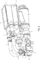
- the fluid extractor assembly 8 includes a tributary tubular member (hereinafter referred to as a main duct 80) and a tubular member (hereinafter referred to as an upstream duct 801).
- the main duct 80 has an upstream section 81 that is fluidly coupled to an outlet of the condenser 4, a first downstream section 82 that is oriented transversely (e.g., perpendicularly) with respect to the upstream section 81, a second downstream section 83 that is oriented transversely (e.g., perpendicularly) with respect to the first downstream section 82 and is fluidly coupled with the turbine 6 of the ACM 5, a downstream section elbow 84 that is fluidly interposed between the first and second downstream sections 82 and 83.
- the main duct 80 further includes a main duct elbow 85 that is fluidly interposed between the upstream section 81 and the first downstream section 82.
- the main duct elbow 85 is formed such that the main duct 80 also includes a first torus sector 850 and a second torus sector 851 at the main duct elbow 85 and at least an upstream portion of the first downstream section 82.
- the first torus sector 850 is formed to define a first aperture 852 and the second torus sector 851 is formed to define a second aperture 853.
- the first torus sector 850 may be provided as an exterior shell of the main duct elbow 85 and the second torus sector 851 is disposed within the first torus sector 850 beginning at the main duct elbow 85 and continuing through the first downstream section 82.
- the second torus sector 851 thus forms a central flow path 854 within an interior surface thereof and a condensate collection gap 855 of increasing cross-sectional flow area in a downstream direction about the central flow path 854 and between an exterior surface of the second torus sector 851 and an interior surface of the first torus sector 850.
- the upstream duct 801 is disposed substantially in parallel with the first downstream section 82 and extends through the first and second apertures 852 and 853 to thereby provide for fluid communication with the downstream section 82.
- the third fluid moves through the upstream duct 801, the first aperture 852 and the second aperture 853 and from there into and through the first downstream section 82, the third fluid flows along a substantially straight line and is exposed to limited or no pipe bends and corresponding changes of flow direction.
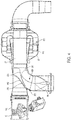
- the first aperture 852 may have a continuous taper 856 that has a steadily increasing positive radius of curvature, an inflexion point and then a steadily increasing negative radius of curvature along each side of the upstream duct 801.
- the second aperture 853, on the other hand, may have a non-continuous taper 857 that may be characterized with a primary angular edge that splits into secondary angular edges on each side of the second torus sector 851.
- the fluid extractor assembly 8 may include fluid extractor swirl vanes 86 and a fluid extractor 87.
- the fluid extractor swirl vanes 86 are disposable in the upstream section 81 and are configured to rotatably drive the first fluid, which is contained within or carried by the second fluid proceeding into the central flow path 854, into the condensate collection gap 855.
- the upstream duct 801 is fluidly communicative with the main duct 80 downstream from the fluid extractor swirl vanes 86.
- the fluid extractor 87 is receptive of the first fluid from the condensate collection gap 855 and includes an annular body 870, which is formed to define a condensate settling chamber 871, and which is operably disposed about the first downstream section 82.
Landscapes
- Engineering & Computer Science (AREA)
- Physics & Mathematics (AREA)
- Thermal Sciences (AREA)
- General Engineering & Computer Science (AREA)
- Mechanical Engineering (AREA)
- Aviation & Aerospace Engineering (AREA)
- Health & Medical Sciences (AREA)
- Pulmonology (AREA)
- General Health & Medical Sciences (AREA)
- Chemical & Material Sciences (AREA)
- Chemical Kinetics & Catalysis (AREA)
- Oil, Petroleum & Natural Gas (AREA)
- General Chemical & Material Sciences (AREA)
- Analytical Chemistry (AREA)
- Control Of Turbines (AREA)
- Structures Of Non-Positive Displacement Pumps (AREA)
- Quick-Acting Or Multi-Walled Pipe Joints (AREA)
- Pipe Accessories (AREA)
- Extraction Or Liquid Replacement (AREA)
Applications Claiming Priority (1)
| Application Number | Priority Date | Filing Date | Title |
|---|---|---|---|
| US14/995,710 US10730630B2 (en) | 2016-01-14 | 2016-01-14 | Low pressure pack |
Publications (2)
| Publication Number | Publication Date |
|---|---|
| EP3196122A1 true EP3196122A1 (fr) | 2017-07-26 |
| EP3196122B1 EP3196122B1 (fr) | 2019-09-04 |
Family
ID=57796212
Family Applications (1)
| Application Number | Title | Priority Date | Filing Date |
|---|---|---|---|
| EP17151193.4A Active EP3196122B1 (fr) | 2016-01-14 | 2017-01-12 | Emballage basse pression pour avion |
Country Status (5)
| Country | Link |
|---|---|
| US (3) | US10730630B2 (fr) |
| EP (1) | EP3196122B1 (fr) |
| CN (1) | CN107031848B (fr) |
| BR (1) | BR102017000773B1 (fr) |
| CA (1) | CA2954449C (fr) |
Families Citing this family (6)
| Publication number | Priority date | Publication date | Assignee | Title |
|---|---|---|---|---|
| US10730630B2 (en) * | 2016-01-14 | 2020-08-04 | Hamilton Sundstrand Corporation | Low pressure pack |
| US11161616B2 (en) * | 2017-04-27 | 2021-11-02 | Textron Innovations, Inc. | High efficiency pneumatic flow control system for aircraft |
| US11117669B2 (en) | 2018-07-30 | 2021-09-14 | Gulfstream Aerospace Corporation | Vane assembly for distribution of a stratified fluid in an aircraft |
| US11154804B2 (en) | 2018-12-07 | 2021-10-26 | Hamilton Sundstrand Corporation | Water extractors and methods of making water extractors |
| EP3944888B1 (fr) * | 2020-07-29 | 2026-04-08 | Hamilton Sundstrand Corporation | Collecteur d'eau annulaire à haute pression comprenant des ailettes de tourbillonnement axiales pour un système de commande environnemental à cycle d'air |
| US12065251B2 (en) * | 2021-06-29 | 2024-08-20 | Hamilton Sundstrand Corporation | Centrifugal water collector with conical water scupper |
Citations (3)
| Publication number | Priority date | Publication date | Assignee | Title |
|---|---|---|---|---|
| US5624140A (en) * | 1993-11-15 | 1997-04-29 | Enfield Industrial Corporation | Double containment pipe fitting |
| US20060021356A1 (en) * | 2004-07-28 | 2006-02-02 | Bertram Milde | Water separator for air-conditioning systems |
| US20060275717A1 (en) * | 2005-03-18 | 2006-12-07 | Honeywell International, Inc. | Apparatus and method for extracting condensate |
Family Cites Families (42)
| Publication number | Priority date | Publication date | Assignee | Title |
|---|---|---|---|---|
| US2929224A (en) * | 1955-12-23 | 1960-03-22 | Garrett Corp | Gas turbine compressor driven air conditioning system |
| US3270775A (en) * | 1963-04-09 | 1966-09-06 | Gen Electric | Diverter valve assembly |
| US3311161A (en) | 1963-09-09 | 1967-03-28 | Boeing Co | Cabin air conditioning systems for aircraft |
| US4262495A (en) | 1979-09-20 | 1981-04-21 | The Boeing Company | Cabin-air recirculation system powered by cabin-to-ambient pressure differential |
| US4430867A (en) * | 1981-08-24 | 1984-02-14 | United Technologies Corporation | Air cycle refrigeration system |
| FR2617570B1 (fr) | 1987-06-30 | 1989-12-01 | Framatome Sa | Dispositif anti-stratification thermique pour tuyau d'alimentation de generateur de vapeur |
| US4963174A (en) * | 1989-12-12 | 1990-10-16 | Payne George K | Hybrid vapor cycle/air cycle environmental control system |
| US5461882A (en) * | 1994-07-22 | 1995-10-31 | United Technologies Corporation | Regenerative condensing cycle |
| US5704218A (en) * | 1996-04-08 | 1998-01-06 | United Technologies Corporation | Integrated environmental control system |
| WO1999002401A1 (fr) * | 1997-07-11 | 1999-01-21 | Alliedsignal Inc. | Systeme de conditionnement d'air a circuit d'air avec condensation assistee par systeme a circuit de vapeur |
| US5887445A (en) * | 1997-11-11 | 1999-03-30 | Alliedsignal Inc. | Two spool environmental control system |
| JP4170492B2 (ja) * | 1999-01-18 | 2008-10-22 | 株式会社島津製作所 | 航空機の環境制御装置 |
| JP4023018B2 (ja) * | 1999-01-19 | 2007-12-19 | 株式会社島津製作所 | 航空機の環境制御装置 |
| US6199387B1 (en) * | 1999-07-30 | 2001-03-13 | Liebherr-Aerospace Lindenberg Gmbh | Air-conditioning system for airplane cabin |
| US6250097B1 (en) * | 1999-10-12 | 2001-06-26 | Alliedsignal Inc. | Dual expansion energy recovery (DEER) air cycle system with mid pressure water separation |
| US6257003B1 (en) * | 2000-08-04 | 2001-07-10 | Hamilton Sundstrand Corporation | Environmental control system utilizing two air cycle machines |
| US6457318B1 (en) * | 2000-11-07 | 2002-10-01 | Honeywell International Inc. | Recirculating regenerative air cycle |
| US6526775B1 (en) * | 2001-09-14 | 2003-03-04 | The Boeing Company | Electric air conditioning system for an aircraft |
| EP1492704B1 (fr) * | 2002-04-08 | 2006-12-06 | Honeywell Normalair-Garrett (Holdings) Limited | Systeme de climatisation |
| AU2003267040B2 (en) * | 2002-09-02 | 2006-12-21 | Shell Internationale Research Maatschappij B.V. | Cyclonic fluid separator |
| US7000425B2 (en) * | 2003-03-12 | 2006-02-21 | Hamilton Sundstrand | Manifold for pack and a half condensing cycle pack with combined heat exchangers |
| GB0314757D0 (en) | 2003-06-25 | 2003-07-30 | Honeywell Normalair Garrett | Air conditioning system |
| US20070113579A1 (en) * | 2004-08-25 | 2007-05-24 | Claeys Henry M | Low energy electric air cycle with portal shroud cabin air compressor |
| US7470300B2 (en) * | 2005-12-07 | 2008-12-30 | Honeywell International Inc. | Duct wall water extractor |
| US7607318B2 (en) * | 2006-05-25 | 2009-10-27 | Honeywell International Inc. | Integrated environmental control and auxiliary power system for an aircraft |
| US20080110193A1 (en) * | 2006-11-10 | 2008-05-15 | Honeywell International Inc. | Environmental control system with adsorption based water removal |
| DE102008024503A1 (de) * | 2008-05-21 | 2009-12-03 | Airbus Deutschland Gmbh | Inertisierungssystem für ein Flugzeug |
| US9669936B1 (en) * | 2012-10-24 | 2017-06-06 | The Boeing Company | Aircraft air conditioning systems and methods |
| BR112016019211A2 (pt) * | 2014-02-21 | 2017-10-17 | Taleris Global Llp | método de diagnóstico de uma falha em uma unidade de ar-condicionado de uma aeronave |
| EP2947012B1 (fr) * | 2014-05-19 | 2017-07-05 | Airbus Operations GmbH | Système de conditionnement d'air pour aéronef et procédé de son opération |
| US20160047561A1 (en) * | 2014-08-12 | 2016-02-18 | Hamilton Sundstrand Corporation | Multi-port compressor manifold with integral bypass valve |
| US10895523B2 (en) * | 2015-04-30 | 2021-01-19 | The University Of Connecticut | Method of optimal sensor selection and fusion for heat exchanger fouling diagnosis in aerospace systems |
| US10160547B2 (en) * | 2015-05-26 | 2018-12-25 | Hamilton Sundstrand Corporation | Aircraft environmental control system |
| CN107690407A (zh) * | 2015-06-08 | 2018-02-13 | 哈米尔顿森德斯特兰德公司 | 无初级换热器和排气(机舱放气)辅助 |
| US10224556B2 (en) * | 2015-12-15 | 2019-03-05 | Hamilton Sundstrand Corporation | Integrated fuel cell aircraft pressurization and cooling system |
| US10730630B2 (en) * | 2016-01-14 | 2020-08-04 | Hamilton Sundstrand Corporation | Low pressure pack |
| US20170268837A1 (en) * | 2016-03-16 | 2017-09-21 | Hamilton Sundstrand Corporation | Pack-and-a-half architecture for environmental control systems |
| US11459110B2 (en) * | 2016-04-22 | 2022-10-04 | Hamilton Sunstrand Corporation | Environmental control system utilizing two pass secondary heat exchanger and cabin pressure assist |
| US10850853B2 (en) * | 2016-04-22 | 2020-12-01 | Hamilton Sunstrand Corporation | Environmental control system utilizing bleed pressure assist |
| US10822095B2 (en) * | 2017-01-27 | 2020-11-03 | Hamilton Sundstrand Corporation | Advanced environmental control system in an integrated pack arrangement with one bleed/outflow heat exchanger |
| US10745137B2 (en) * | 2017-01-27 | 2020-08-18 | Hamilton Sunstrand Corporation | Advanced environmental control system in an integrated split pack arrangement with one bleed/outflow heat exchanger |
| US10493820B2 (en) * | 2017-09-08 | 2019-12-03 | Honeywell International Inc. | Coating of the ECS primary heat exchanger (PHX) with low temperature catalyst for ozone and/or volatile organic compounds (VOC) and/or carbon monoxide conversion |
-
2016
- 2016-01-14 US US14/995,710 patent/US10730630B2/en active Active
-
2017
- 2017-01-10 CA CA2954449A patent/CA2954449C/fr active Active
- 2017-01-12 EP EP17151193.4A patent/EP3196122B1/fr active Active
- 2017-01-13 CN CN201710024214.6A patent/CN107031848B/zh active Active
- 2017-01-13 BR BR102017000773-1A patent/BR102017000773B1/pt active IP Right Grant
-
2020
- 2020-05-21 US US16/880,123 patent/US11578902B2/en active Active
- 2020-05-21 US US16/880,127 patent/US11614261B2/en active Active
Patent Citations (3)
| Publication number | Priority date | Publication date | Assignee | Title |
|---|---|---|---|---|
| US5624140A (en) * | 1993-11-15 | 1997-04-29 | Enfield Industrial Corporation | Double containment pipe fitting |
| US20060021356A1 (en) * | 2004-07-28 | 2006-02-02 | Bertram Milde | Water separator for air-conditioning systems |
| US20060275717A1 (en) * | 2005-03-18 | 2006-12-07 | Honeywell International, Inc. | Apparatus and method for extracting condensate |
Also Published As
| Publication number | Publication date |
|---|---|
| US11578902B2 (en) | 2023-02-14 |
| CA2954449C (fr) | 2026-02-10 |
| US10730630B2 (en) | 2020-08-04 |
| EP3196122B1 (fr) | 2019-09-04 |
| CA2954449A1 (fr) | 2017-07-14 |
| CN107031848A (zh) | 2017-08-11 |
| US11614261B2 (en) | 2023-03-28 |
| US20200283155A1 (en) | 2020-09-10 |
| BR102017000773B1 (pt) | 2023-03-07 |
| CN107031848B (zh) | 2022-02-22 |
| BR102017000773A2 (pt) | 2017-08-22 |
| US20170203845A1 (en) | 2017-07-20 |
| US20200283154A1 (en) | 2020-09-10 |
Similar Documents
| Publication | Publication Date | Title |
|---|---|---|
| US11578902B2 (en) | Low pressure pack | |
| EP2845804B1 (fr) | Système de commande environnementale (ECS) comprenant un dispositif de compression | |
| US10384785B2 (en) | Two mode system that provides bleed and outside air or just outside air | |
| EP3249198B1 (fr) | Mélange d'air dynamique et d'air de purge dans un système de turbine à entrée double | |
| EP3249196B1 (fr) | Flux d'énergie d'un système de commande environnemental avancé | |
| EP3248877B1 (fr) | Mélange d'air de purge et d'air dynamique à une entrée de turbine | |
| US10486817B2 (en) | Environmental control system with an outflow heat exchanger | |
| EP3248880B1 (fr) | Mélange d'air dynamique et d'air de purge dans un système de turbine à entrée double | |
| EP3662984B1 (fr) | Extracteurs d'eau et procédés de fabrication d'extracteurs d'eau | |
| EP3385169B1 (fr) | Troisième pack d'air conditionné hybride | |
| CN109665106B (zh) | 由放出空气和机舱空气驱动的补充组件 | |
| US20170030265A1 (en) | Bleed air valve a turbine engine with anti-ice valve assembly and method of operating | |
| EP3395687B1 (fr) | Système d'air conditionné avec bloc de cycle simple intégré | |
| US10001062B2 (en) | Aircraft turbine engine comprising an air intake housing with a variable aerodynamic profile | |
| US20150098805A1 (en) | Insulating seal plate for an air cycle machine | |
| EP3296208B1 (fr) | Aeronef comprenant un systeme de recuperation d'air de cabine | |
| EP3842344B1 (fr) | Aéronef | |
| EP3023330B1 (fr) | Ensemble échangeur de chaleur pour systèmes de contrôle de l'environnement (ecs) d'aéronef | |
| EP3192740B1 (fr) | Dispositif à orifice de trou de vidange | |
| EP3225554B1 (fr) | Système de climatisation d'aéronef comprenant un dispositif thermoélectrique |
Legal Events
| Date | Code | Title | Description |
|---|---|---|---|
| PUAI | Public reference made under article 153(3) epc to a published international application that has entered the european phase |
Free format text: ORIGINAL CODE: 0009012 |
|
| STAA | Information on the status of an ep patent application or granted ep patent |
Free format text: STATUS: THE APPLICATION HAS BEEN PUBLISHED |
|
| AK | Designated contracting states |
Kind code of ref document: A1 Designated state(s): AL AT BE BG CH CY CZ DE DK EE ES FI FR GB GR HR HU IE IS IT LI LT LU LV MC MK MT NL NO PL PT RO RS SE SI SK SM TR |
|
| AX | Request for extension of the european patent |
Extension state: BA ME |
|
| STAA | Information on the status of an ep patent application or granted ep patent |
Free format text: STATUS: REQUEST FOR EXAMINATION WAS MADE |
|
| 17P | Request for examination filed |
Effective date: 20180126 |
|
| RBV | Designated contracting states (corrected) |
Designated state(s): AL AT BE BG CH CY CZ DE DK EE ES FI FR GB GR HR HU IE IS IT LI LT LU LV MC MK MT NL NO PL PT RO RS SE SI SK SM TR |
|
| GRAP | Despatch of communication of intention to grant a patent |
Free format text: ORIGINAL CODE: EPIDOSNIGR1 |
|
| STAA | Information on the status of an ep patent application or granted ep patent |
Free format text: STATUS: GRANT OF PATENT IS INTENDED |
|
| INTG | Intention to grant announced |
Effective date: 20190322 |
|
| RAP1 | Party data changed (applicant data changed or rights of an application transferred) |
Owner name: HAMILTON SUNDSTRAND CORPORATION |
|
| GRAS | Grant fee paid |
Free format text: ORIGINAL CODE: EPIDOSNIGR3 |
|
| GRAA | (expected) grant |
Free format text: ORIGINAL CODE: 0009210 |
|
| STAA | Information on the status of an ep patent application or granted ep patent |
Free format text: STATUS: THE PATENT HAS BEEN GRANTED |
|
| AK | Designated contracting states |
Kind code of ref document: B1 Designated state(s): AL AT BE BG CH CY CZ DE DK EE ES FI FR GB GR HR HU IE IS IT LI LT LU LV MC MK MT NL NO PL PT RO RS SE SI SK SM TR |
|
| REG | Reference to a national code |
Ref country code: GB Ref legal event code: FG4D |
|
| REG | Reference to a national code |
Ref country code: CH Ref legal event code: EP |
|
| REG | Reference to a national code |
Ref country code: AT Ref legal event code: REF Ref document number: 1174993 Country of ref document: AT Kind code of ref document: T Effective date: 20190915 |
|
| REG | Reference to a national code |
Ref country code: DE Ref legal event code: R096 Ref document number: 602017006611 Country of ref document: DE |
|
| REG | Reference to a national code |
Ref country code: IE Ref legal event code: FG4D |
|
| REG | Reference to a national code |
Ref country code: NL Ref legal event code: MP Effective date: 20190904 |
|
| REG | Reference to a national code |
Ref country code: LT Ref legal event code: MG4D |
|
| PG25 | Lapsed in a contracting state [announced via postgrant information from national office to epo] |
Ref country code: NO Free format text: LAPSE BECAUSE OF FAILURE TO SUBMIT A TRANSLATION OF THE DESCRIPTION OR TO PAY THE FEE WITHIN THE PRESCRIBED TIME-LIMIT Effective date: 20191204 Ref country code: BG Free format text: LAPSE BECAUSE OF FAILURE TO SUBMIT A TRANSLATION OF THE DESCRIPTION OR TO PAY THE FEE WITHIN THE PRESCRIBED TIME-LIMIT Effective date: 20191204 Ref country code: SE Free format text: LAPSE BECAUSE OF FAILURE TO SUBMIT A TRANSLATION OF THE DESCRIPTION OR TO PAY THE FEE WITHIN THE PRESCRIBED TIME-LIMIT Effective date: 20190904 Ref country code: FI Free format text: LAPSE BECAUSE OF FAILURE TO SUBMIT A TRANSLATION OF THE DESCRIPTION OR TO PAY THE FEE WITHIN THE PRESCRIBED TIME-LIMIT Effective date: 20190904 Ref country code: LT Free format text: LAPSE BECAUSE OF FAILURE TO SUBMIT A TRANSLATION OF THE DESCRIPTION OR TO PAY THE FEE WITHIN THE PRESCRIBED TIME-LIMIT Effective date: 20190904 Ref country code: HR Free format text: LAPSE BECAUSE OF FAILURE TO SUBMIT A TRANSLATION OF THE DESCRIPTION OR TO PAY THE FEE WITHIN THE PRESCRIBED TIME-LIMIT Effective date: 20190904 |
|
| PG25 | Lapsed in a contracting state [announced via postgrant information from national office to epo] |
Ref country code: ES Free format text: LAPSE BECAUSE OF FAILURE TO SUBMIT A TRANSLATION OF THE DESCRIPTION OR TO PAY THE FEE WITHIN THE PRESCRIBED TIME-LIMIT Effective date: 20190904 Ref country code: GR Free format text: LAPSE BECAUSE OF FAILURE TO SUBMIT A TRANSLATION OF THE DESCRIPTION OR TO PAY THE FEE WITHIN THE PRESCRIBED TIME-LIMIT Effective date: 20191205 Ref country code: LV Free format text: LAPSE BECAUSE OF FAILURE TO SUBMIT A TRANSLATION OF THE DESCRIPTION OR TO PAY THE FEE WITHIN THE PRESCRIBED TIME-LIMIT Effective date: 20190904 Ref country code: RS Free format text: LAPSE BECAUSE OF FAILURE TO SUBMIT A TRANSLATION OF THE DESCRIPTION OR TO PAY THE FEE WITHIN THE PRESCRIBED TIME-LIMIT Effective date: 20190904 Ref country code: AL Free format text: LAPSE BECAUSE OF FAILURE TO SUBMIT A TRANSLATION OF THE DESCRIPTION OR TO PAY THE FEE WITHIN THE PRESCRIBED TIME-LIMIT Effective date: 20190904 |
|
| REG | Reference to a national code |
Ref country code: AT Ref legal event code: MK05 Ref document number: 1174993 Country of ref document: AT Kind code of ref document: T Effective date: 20190904 |
|
| PG25 | Lapsed in a contracting state [announced via postgrant information from national office to epo] |
Ref country code: PT Free format text: LAPSE BECAUSE OF FAILURE TO SUBMIT A TRANSLATION OF THE DESCRIPTION OR TO PAY THE FEE WITHIN THE PRESCRIBED TIME-LIMIT Effective date: 20200106 Ref country code: EE Free format text: LAPSE BECAUSE OF FAILURE TO SUBMIT A TRANSLATION OF THE DESCRIPTION OR TO PAY THE FEE WITHIN THE PRESCRIBED TIME-LIMIT Effective date: 20190904 Ref country code: PL Free format text: LAPSE BECAUSE OF FAILURE TO SUBMIT A TRANSLATION OF THE DESCRIPTION OR TO PAY THE FEE WITHIN THE PRESCRIBED TIME-LIMIT Effective date: 20190904 Ref country code: AT Free format text: LAPSE BECAUSE OF FAILURE TO SUBMIT A TRANSLATION OF THE DESCRIPTION OR TO PAY THE FEE WITHIN THE PRESCRIBED TIME-LIMIT Effective date: 20190904 Ref country code: RO Free format text: LAPSE BECAUSE OF FAILURE TO SUBMIT A TRANSLATION OF THE DESCRIPTION OR TO PAY THE FEE WITHIN THE PRESCRIBED TIME-LIMIT Effective date: 20190904 Ref country code: IT Free format text: LAPSE BECAUSE OF FAILURE TO SUBMIT A TRANSLATION OF THE DESCRIPTION OR TO PAY THE FEE WITHIN THE PRESCRIBED TIME-LIMIT Effective date: 20190904 Ref country code: NL Free format text: LAPSE BECAUSE OF FAILURE TO SUBMIT A TRANSLATION OF THE DESCRIPTION OR TO PAY THE FEE WITHIN THE PRESCRIBED TIME-LIMIT Effective date: 20190904 |
|
| PG25 | Lapsed in a contracting state [announced via postgrant information from national office to epo] |
Ref country code: IS Free format text: LAPSE BECAUSE OF FAILURE TO SUBMIT A TRANSLATION OF THE DESCRIPTION OR TO PAY THE FEE WITHIN THE PRESCRIBED TIME-LIMIT Effective date: 20200224 Ref country code: CZ Free format text: LAPSE BECAUSE OF FAILURE TO SUBMIT A TRANSLATION OF THE DESCRIPTION OR TO PAY THE FEE WITHIN THE PRESCRIBED TIME-LIMIT Effective date: 20190904 Ref country code: SK Free format text: LAPSE BECAUSE OF FAILURE TO SUBMIT A TRANSLATION OF THE DESCRIPTION OR TO PAY THE FEE WITHIN THE PRESCRIBED TIME-LIMIT Effective date: 20190904 Ref country code: SM Free format text: LAPSE BECAUSE OF FAILURE TO SUBMIT A TRANSLATION OF THE DESCRIPTION OR TO PAY THE FEE WITHIN THE PRESCRIBED TIME-LIMIT Effective date: 20190904 |
|
| REG | Reference to a national code |
Ref country code: DE Ref legal event code: R097 Ref document number: 602017006611 Country of ref document: DE |
|
| PLBE | No opposition filed within time limit |
Free format text: ORIGINAL CODE: 0009261 |
|
| STAA | Information on the status of an ep patent application or granted ep patent |
Free format text: STATUS: NO OPPOSITION FILED WITHIN TIME LIMIT |
|
| PG2D | Information on lapse in contracting state deleted |
Ref country code: IS |
|
| PG25 | Lapsed in a contracting state [announced via postgrant information from national office to epo] |
Ref country code: DK Free format text: LAPSE BECAUSE OF FAILURE TO SUBMIT A TRANSLATION OF THE DESCRIPTION OR TO PAY THE FEE WITHIN THE PRESCRIBED TIME-LIMIT Effective date: 20190904 Ref country code: IS Free format text: LAPSE BECAUSE OF FAILURE TO SUBMIT A TRANSLATION OF THE DESCRIPTION OR TO PAY THE FEE WITHIN THE PRESCRIBED TIME-LIMIT Effective date: 20200105 |
|
| 26N | No opposition filed |
Effective date: 20200605 |
|
| PG25 | Lapsed in a contracting state [announced via postgrant information from national office to epo] |
Ref country code: MC Free format text: LAPSE BECAUSE OF FAILURE TO SUBMIT A TRANSLATION OF THE DESCRIPTION OR TO PAY THE FEE WITHIN THE PRESCRIBED TIME-LIMIT Effective date: 20190904 Ref country code: SI Free format text: LAPSE BECAUSE OF FAILURE TO SUBMIT A TRANSLATION OF THE DESCRIPTION OR TO PAY THE FEE WITHIN THE PRESCRIBED TIME-LIMIT Effective date: 20190904 |
|
| REG | Reference to a national code |
Ref country code: CH Ref legal event code: PL |
|
| REG | Reference to a national code |
Ref country code: BE Ref legal event code: MM Effective date: 20200131 |
|
| PG25 | Lapsed in a contracting state [announced via postgrant information from national office to epo] |
Ref country code: LU Free format text: LAPSE BECAUSE OF NON-PAYMENT OF DUE FEES Effective date: 20200112 |
|
| PG25 | Lapsed in a contracting state [announced via postgrant information from national office to epo] |
Ref country code: LI Free format text: LAPSE BECAUSE OF NON-PAYMENT OF DUE FEES Effective date: 20200131 Ref country code: CH Free format text: LAPSE BECAUSE OF NON-PAYMENT OF DUE FEES Effective date: 20200131 Ref country code: BE Free format text: LAPSE BECAUSE OF NON-PAYMENT OF DUE FEES Effective date: 20200131 |
|
| PG25 | Lapsed in a contracting state [announced via postgrant information from national office to epo] |
Ref country code: IE Free format text: LAPSE BECAUSE OF NON-PAYMENT OF DUE FEES Effective date: 20200112 |
|
| PG25 | Lapsed in a contracting state [announced via postgrant information from national office to epo] |
Ref country code: TR Free format text: LAPSE BECAUSE OF FAILURE TO SUBMIT A TRANSLATION OF THE DESCRIPTION OR TO PAY THE FEE WITHIN THE PRESCRIBED TIME-LIMIT Effective date: 20190904 Ref country code: MT Free format text: LAPSE BECAUSE OF FAILURE TO SUBMIT A TRANSLATION OF THE DESCRIPTION OR TO PAY THE FEE WITHIN THE PRESCRIBED TIME-LIMIT Effective date: 20190904 Ref country code: CY Free format text: LAPSE BECAUSE OF FAILURE TO SUBMIT A TRANSLATION OF THE DESCRIPTION OR TO PAY THE FEE WITHIN THE PRESCRIBED TIME-LIMIT Effective date: 20190904 |
|
| PG25 | Lapsed in a contracting state [announced via postgrant information from national office to epo] |
Ref country code: MK Free format text: LAPSE BECAUSE OF FAILURE TO SUBMIT A TRANSLATION OF THE DESCRIPTION OR TO PAY THE FEE WITHIN THE PRESCRIBED TIME-LIMIT Effective date: 20190904 |
|
| P01 | Opt-out of the competence of the unified patent court (upc) registered |
Effective date: 20230522 |
|
| PGFP | Annual fee paid to national office [announced via postgrant information from national office to epo] |
Ref country code: GB Payment date: 20251219 Year of fee payment: 10 |
|
| PGFP | Annual fee paid to national office [announced via postgrant information from national office to epo] |
Ref country code: FR Payment date: 20251217 Year of fee payment: 10 |
|
| PGFP | Annual fee paid to national office [announced via postgrant information from national office to epo] |
Ref country code: DE Payment date: 20251217 Year of fee payment: 10 |