EP3196372A1 - Wärmedämmsystem und -verfahren, bei dem verbundpaneele zur definition einer dämmschicht für piv-elemente verwendet werden - Google Patents
Wärmedämmsystem und -verfahren, bei dem verbundpaneele zur definition einer dämmschicht für piv-elemente verwendet werden Download PDFInfo
- Publication number
- EP3196372A1 EP3196372A1 EP17152065.3A EP17152065A EP3196372A1 EP 3196372 A1 EP3196372 A1 EP 3196372A1 EP 17152065 A EP17152065 A EP 17152065A EP 3196372 A1 EP3196372 A1 EP 3196372A1
- Authority
- EP
- European Patent Office
- Prior art keywords
- cover plate
- insulating
- thermal insulation
- edge
- plate
- Prior art date
- Legal status (The legal status is an assumption and is not a legal conclusion. Google has not performed a legal analysis and makes no representation as to the accuracy of the status listed.)
- Granted
Links
Images


Classifications
-
- E—FIXED CONSTRUCTIONS
- E04—BUILDING
- E04F—FINISHING WORK ON BUILDINGS, e.g. STAIRS, FLOORS
- E04F13/00—Coverings or linings, e.g. for walls or ceilings
- E04F13/07—Coverings or linings, e.g. for walls or ceilings composed of covering or lining elements; Sub-structures therefor; Fastening means therefor
- E04F13/08—Coverings or linings, e.g. for walls or ceilings composed of covering or lining elements; Sub-structures therefor; Fastening means therefor composed of a plurality of similar covering or lining elements
- E04F13/0875—Coverings or linings, e.g. for walls or ceilings composed of covering or lining elements; Sub-structures therefor; Fastening means therefor composed of a plurality of similar covering or lining elements having a basic insulating layer and at least one covering layer
- E04F13/0878—Coverings or linings, e.g. for walls or ceilings composed of covering or lining elements; Sub-structures therefor; Fastening means therefor composed of a plurality of similar covering or lining elements having a basic insulating layer and at least one covering layer the basic insulating layer comprising mutual alignment or interlocking means
-
- E—FIXED CONSTRUCTIONS
- E04—BUILDING
- E04B—GENERAL BUILDING CONSTRUCTIONS; WALLS, e.g. PARTITIONS; ROOFS; FLOORS; CEILINGS; INSULATION OR OTHER PROTECTION OF BUILDINGS
- E04B1/00—Constructions in general; Structures which are not restricted either to walls, e.g. partitions, or floors or ceilings or roofs
- E04B1/62—Insulation or other protection; Elements or use of specified material therefor
- E04B1/74—Heat, sound or noise insulation, absorption, or reflection; Other building methods affording favourable thermal or acoustical conditions, e.g. accumulating of heat within walls
- E04B1/76—Heat, sound or noise insulation, absorption, or reflection; Other building methods affording favourable thermal or acoustical conditions, e.g. accumulating of heat within walls specifically with respect to heat only
- E04B1/78—Heat insulating elements
- E04B1/80—Heat insulating elements slab-shaped
- E04B1/803—Heat insulating elements slab-shaped with vacuum spaces included in the slab
-
- E—FIXED CONSTRUCTIONS
- E04—BUILDING
- E04F—FINISHING WORK ON BUILDINGS, e.g. STAIRS, FLOORS
- E04F13/00—Coverings or linings, e.g. for walls or ceilings
- E04F13/07—Coverings or linings, e.g. for walls or ceilings composed of covering or lining elements; Sub-structures therefor; Fastening means therefor
- E04F13/08—Coverings or linings, e.g. for walls or ceilings composed of covering or lining elements; Sub-structures therefor; Fastening means therefor composed of a plurality of similar covering or lining elements
- E04F13/0889—Coverings or linings, e.g. for walls or ceilings composed of covering or lining elements; Sub-structures therefor; Fastening means therefor composed of a plurality of similar covering or lining elements characterised by the joints between neighbouring elements, e.g. with joint fillings or with tongue and groove connections
- E04F13/0894—Coverings or linings, e.g. for walls or ceilings composed of covering or lining elements; Sub-structures therefor; Fastening means therefor composed of a plurality of similar covering or lining elements characterised by the joints between neighbouring elements, e.g. with joint fillings or with tongue and groove connections with tongue and groove connections
-
- E—FIXED CONSTRUCTIONS
- E04—BUILDING
- E04F—FINISHING WORK ON BUILDINGS, e.g. STAIRS, FLOORS
- E04F13/00—Coverings or linings, e.g. for walls or ceilings
- E04F13/07—Coverings or linings, e.g. for walls or ceilings composed of covering or lining elements; Sub-structures therefor; Fastening means therefor
- E04F13/08—Coverings or linings, e.g. for walls or ceilings composed of covering or lining elements; Sub-structures therefor; Fastening means therefor composed of a plurality of similar covering or lining elements
- E04F13/14—Coverings or linings, e.g. for walls or ceilings composed of covering or lining elements; Sub-structures therefor; Fastening means therefor composed of a plurality of similar covering or lining elements stone or stone-like materials, e.g. ceramics concrete; of glass or with an outer layer of stone or stone-like materials or glass
-
- E—FIXED CONSTRUCTIONS
- E04—BUILDING
- E04F—FINISHING WORK ON BUILDINGS, e.g. STAIRS, FLOORS
- E04F13/00—Coverings or linings, e.g. for walls or ceilings
- E04F13/07—Coverings or linings, e.g. for walls or ceilings composed of covering or lining elements; Sub-structures therefor; Fastening means therefor
- E04F13/08—Coverings or linings, e.g. for walls or ceilings composed of covering or lining elements; Sub-structures therefor; Fastening means therefor composed of a plurality of similar covering or lining elements
- E04F13/18—Coverings or linings, e.g. for walls or ceilings composed of covering or lining elements; Sub-structures therefor; Fastening means therefor composed of a plurality of similar covering or lining elements of organic plastics with or without reinforcements or filling materials or with an outer layer of organic plastics with or without reinforcements or filling materials; plastic tiles
-
- Y—GENERAL TAGGING OF NEW TECHNOLOGICAL DEVELOPMENTS; GENERAL TAGGING OF CROSS-SECTIONAL TECHNOLOGIES SPANNING OVER SEVERAL SECTIONS OF THE IPC; TECHNICAL SUBJECTS COVERED BY FORMER USPC CROSS-REFERENCE ART COLLECTIONS [XRACs] AND DIGESTS
- Y02—TECHNOLOGIES OR APPLICATIONS FOR MITIGATION OR ADAPTATION AGAINST CLIMATE CHANGE
- Y02A—TECHNOLOGIES FOR ADAPTATION TO CLIMATE CHANGE
- Y02A30/00—Adapting or protecting infrastructure or their operation
- Y02A30/24—Structural elements or technologies for improving thermal insulation
- Y02A30/242—Slab shaped vacuum insulation
-
- Y—GENERAL TAGGING OF NEW TECHNOLOGICAL DEVELOPMENTS; GENERAL TAGGING OF CROSS-SECTIONAL TECHNOLOGIES SPANNING OVER SEVERAL SECTIONS OF THE IPC; TECHNICAL SUBJECTS COVERED BY FORMER USPC CROSS-REFERENCE ART COLLECTIONS [XRACs] AND DIGESTS
- Y02—TECHNOLOGIES OR APPLICATIONS FOR MITIGATION OR ADAPTATION AGAINST CLIMATE CHANGE
- Y02B—CLIMATE CHANGE MITIGATION TECHNOLOGIES RELATED TO BUILDINGS, e.g. HOUSING, HOUSE APPLIANCES OR RELATED END-USER APPLICATIONS
- Y02B80/00—Architectural or constructional elements improving the thermal performance of buildings
- Y02B80/10—Insulation, e.g. vacuum or aerogel insulation
Definitions
- the present invention relates, in the field of building, the thermal insulation installations used for the wall lining.
- the invention relates more particularly to the dubbing systems which incorporate an insulating layer formed of insulating elements of the PIV type (Vacuum Insulation Panel), and at least one typically rigid facing or similar rigid covering elements which define a flat surface .
- the invention also relates to a method of doubling a wall.
- the PIV elements comprise, in a manner known per se, an insulating porous core material (for example with an open-cell microcellular or nanocellular structure) kept under vacuum by a barrier envelope guaranteeing gas-tightness.
- the barrier envelope is flexible and generally incorporates a heat-sealable film.
- These panels form typically rigid plates, of substantially constant thickness, and have large sizes, for example 600 mm in width and 1200 mm in length (other widths, for example of 100, 300 mm, 400, 500 up to at 1200 mm being of course available, the length generally ranging between 500 and 2000 mm).
- the size of these panels would therefore be suitable for covering building walls for thermal insulation purposes.
- the thermal performance of these elementary panels leads to thicknesses that can be reduced to minimize the size of the thermal insulation system, the thickness of a panel being less than 60 mm, and preferably less than or equal to at 35 mm.
- the PIV panels have a thermal conductivity of less than 7 mW m -1 K -1 , and more preferably less than 5 mW m -1 K -1 .
- the relatively large size of the panels and their very low thermal conductivity are very important thermal insulation performance advantages which can, however, be considerably reduced if the spacing between two adjacent panels is too great (problematic thermal bridges) and / or air can circulate at the junctions (associated problem of airtightness of thermal insulation of building walls).
- a disadvantage of the mounting method described in CA 2255988 is that it is not suitable for the use of PIV type panels.
- This document is only intended to isolate with a filling material such as foam, which does not have insulation performance comparable to a PIV type panel.
- the positioning of the retaining rib can waste time and requires the addition of a flexible overlay (eg textile or non-woven) on the side of the interior of the room.
- a flexible overlay eg textile or non-woven
- Such a layer does not form or allow to withstand a rigid finish, unlike plaster boards, faience or similar coating. It is therefore necessary in practice to achieve a finish later.
- the present invention is intended to overcome all or part of the aforementioned drawbacks.
- interlocking composite panels limits thermal bridges while facilitating individual disassembly operations that can then be considered. It is understood that the composite panels can be recovered if necessary after such disassembly.
- composite panels that include a standard vacuum super-insulation intermediate layer (with a brittle barrier envelope) can be used to insulate existing buildings without the need for an air gap. fasteners (screws, cleats, framework) that interfere with the insulating layer.
- the specific cover plate can act as a finishing plate and covers for example an insulating material (completing the insulation layer based on PIV elements) very powerful, conductivity less than or equal to 50 mW m -1 K -1 (and preferably less than 30 mW m -1 K -1 ).
- the PIV elements are contiguous without an interlayer between their slices in the insulating layer.
- each composite panel the fixing and covering plates are held firmly against one side of a PIV-type insulating element, for example by a glue without solvent.
- the interlocking means comprise at least two interlocking reliefs.
- One of these two reliefs may be located on the side of a first outer edge of the composite panel defined by a projecting positioning of an insulating member with respect to a free edge of the cover plate and at a free edge of the fixing plate, and the other located on the side of a second outer edge of the composite panel opposite to the first outer edge.
- One or two overhangs can be formed on the different sides of the composite panel, which facilitates the maintenance of these panels during their installation.
- the invention also relates to a mounting method for producing the thermal insulation system according to the invention from interlocking composite panels and defining four edges.
- the method advantageously allows forming a layer based PIV panels that can be continuous at least in a row is that is simple to assemble on site.
- the insulated wall is well airtight and can be directly finished by the outer surface formed by the cover plates.
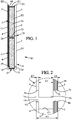
- the composite panel 1 of thermal insulation comprises at least one super insulating element 3 of the PIV type (of typically standard format) having a parallelepipedal format with the same thickness E3 (this thickness E3 being typically the smallest of the dimensions of the superinsulating elements 3).
- Element 3 thus has a plate shape and has two main faces F1 and F2 and four slices 31, 32, 33, 34 (see FIG. figure 3 ), with here two opposite slices 31, 32 which are preferably parallel to form the lower and upper ends of the element 3.
- the porous material 3a present inside the barrier envelope 2 is resistant to compression (it is typically rigid, unlike the flexible film forming the barrier envelope 2).
- the porous material 3a is enclosed under vacuum by the gas-tight barrier envelope 2.
- the barrier envelope 2 retracts on this porous material 3a when it is subjected externally to atmospheric pressure.
- the porous material 3a preferably defines at least 90% of the total thickness E3 of the element PIV type 3, knowing that the barrier envelope 2 consists of a very thin (generally multilayer) waterproof film whose thickness is much less than 1 mm, and typically less than 0.2 mm.
- the element 3, devoid of mechanical protection, has for example a thickness E3 typically less than or equal to 35 or 40 mm.
- the composite panels 1 in the assembled state comprise a layer at the rear and a layer at the front of the insulating layer 6 (with preservation of a vacuum) defined by the superinsulating elements 3.
- rigid fixing plates 4 form the layer at the rear.
- the insulating layer 6 has a thickness equal to the thickness E3 of an element 3.
- Cover plates 5, parallel to the fixing plates 4, define the outer layer at the front, extending completely outside the insulating layer 6.
- the fixing plates 4 typically form a flat face 4c on which the rear main face F1 of an element 3 is glued or fixed without drilling the face F1.
- the cover plate 5 may be in a rigid block of a piece, for example glued against the front face F2 of the element 3 PIV type.
- the plate includes an articulation formed by a fold line. This can be used to inspect the F2 face of the PIV element after the installation and subsequently to control the integrity of the barrier envelope 2.
- the insertion edge of the removable plate member 5c can optionally be beveled and / or protruded from a shoulder to slide partially under the fastening edge of the fixed member 5d. Projections and / or at least one elongated rib, cooperating in complementary recesses, may allow to maintain the plate member 5c attached to the face F2.
- the snap corresponds to a removable attachment mode.
- Foam, other compressible material, or a thin protective strip may be used as appropriate at the rear of the insertion edge or on the entire rear face of the plate member 5c to prevent aggressive contact against the face F2 defined by the barrier envelope 2.
- the plate element or elements 5c may, if appropriate, be laid in an end-of-installation step, after having formed the insulating layer 6.
- Each composite panel 1 may have a composition in three layers.
- each fixing plate 4 is placed between the wall P and the insulating layer 6 formed by the insulating elements 3. It can be seen that the cover plates 5 may have a finish, which avoids fixing an additional layer or any facing additional.
- the super insulating elements 3 are directly sandwiched between the fixing plate 4 and the cover plate 5 (which can form a finishing plate), forming an integrated nesting system.
- the fixing plates 4 and the cover plates 5 are held together against a respective outer face of a super-insulating member 3 by a glue without solvent.
- At least one of the four slices of the element 3, here the upper slice 32, is entirely recessed with respect to the adjacent edges B1, B2 defined respectively by the upper end (free edge B2) of the fixing plate 4 and the upper end (free edge B1) of the cover plate 5.
- a groove G1 which can receive the projecting end 3b of a complementary composite panel 1.
- the protruding end 3b is defined here by a super-insulating element 3 projecting from this side with respect to a free edge 4a of the cover plate 4 and at a free edge 5a of the fixing plate 5.
- edge free here means that this type of edge is not covered in the unassembled state of the composite panel 1. In the assembled state, the free edges B1 and 5a meet and the same is true for the free edges B2 and 4a.
- At least two interlocking projections are formed for the composite panels 1, one located on the side of a first outer edge 1a of the composite panel 1 and the other located on the side of a second outer edge 1b opposite the first outer edge 1a.
- At least one U-section or possibly L-shaped profile 11 is provided, rigidly attached to a building substrate for supporting the bottom of a first horizontal row R0.
- the lower edges of the composite panels 1 of this row R0 can be entirely housed in a cavity defined by this profile 11.
- the width of the profile 11 is adapted to receive the three layers of the panel 1 and the profile 11 can be visible in FIG. bottom of the common outer face 50 typically defined by the cover plates 5.
- the profile 11 can form a cavity C11 whose width is smaller than the thickness E1 of the composite panels 1, in order to selectively receive projecting ends 3b defined by the insulating elements 3 (here on the lower edge of the panels 1).
- the composite panel 1 which forms a row end, it is possible to remove the interlocking relief and the composite panel 1 can define a single substantially flat face (for example a bottom face) intended to bear against a substrate of the building, for example a floor.
- fastening plates 4 and cover plates 5 which have the same external dimensions within a given composite panel 1 , and which have at least one dimension (other than the thickness) in common within the same row R1 or R2.
- a layer of foam 60, of compressible material, or a thin protective strip, of thickness less than or equal to 3 or 4 mm, may optionally cover the wafer 32 in order to protect it.
- this type of protection can be fixed directly on the plates 4 and / or 5, in the groove G1 as illustrated in FIG. figure 1 .
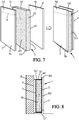
- a layer of foam 60 or the like covers the projections of the plate or plates 4 and / or 20 in a module 22 or 22 '. In the case of figure 8 only the specific cover plate 20 may be locally covered with the foam film 60.
- the fixing plate 4 may advantageously be thinner than the cover plate 5.
- the ratio between the thickness E4 (rear side) and the thickness E5 of the cover plate may be for example between 1.1 and 2.
- the thickness E5 of the cover plate 5 may be between 3 and 20 mm, preferably between 5 and 15 mm while being higher than the thickness E4 of the fixing plate 4.
- Rows can be formed and the nested position between adjacent panels 1 can be formed by using a concave section edge for one of the free edges 5a and B1.
- the cover plate 5 thus has an edge 5a, adjacent to the end 3b, of concave section to form a groove R.
- a groove R may be formed adjacent to one of the two reliefs of 3b interlocking, G1 and is engaged by a complementary edge of convex section belonging to an adjacent cover plate 5, on the other side of the two interlocking reliefs G1, 3b.
- the thickness of the insulating layer 6 is defined by the thickness E 3 of a superinsulating element 3 is illustrated here.
- the total thickness E1 of the composite panel 1 is preferably much less than 100 mm in order to minimize the bulk, for example less than 60 mm, and preferably less than or equal to 50 mm.
- a thickness E1 of less than or equal to 40 mm is more particularly advantageous, and this low level of thickness can be easily achieved for dubbing applications of a building wall P which is flat.
- the signs Composites 1 can fit directly with one another without resorting to intermediate elements.
- the framework can only consist of supports, here profiles 11, 12 and a male element 13, insertion edge or cleat which are placed at the periphery of the lining (thus in the margin with respect to the common outer face 50) .
- the support profiles 11 are each formed of a single block of plastic material, for example polyamide, PVC, polyurethane resin or based on composite materials, glass fibers, optionally with metal particles (for example polyamide PA 66 loaded with 25% glass fibers).
- the lower support profiles 11 and the other profiles 12 or male elements 13 can be made with the same type of material.
- each of these elements of the framework here has a thermal conductivity of less than or equal to 0.6 W m -1 K -1 and preferably less than 0.2 or 0.25 W m - 1 K -1 .
- a thermal conductivity less than or equal to 0.18 W m -1 K -1 is preferred for the material of these elements.
- this type of module 22 allows the passage of fluids and energies used in the building and supplements if necessary the layout of the wall P to isolate. It may be noted that the opening or openings 23, 24 formed through the module 22 are not used for anchoring the thermal insulation system 10.
- a peripheral framework which comprises sections 11, 12 (here in a U-section or in L) and / or elongated elements such as cleats, is used to border all or part of the lower row R0, the upper row and at least one row R2 at the lateral end of the system 10.
- the module 22 is engaged in a lower section 11 of the framework, in the cavity C11 defined by this lower profile 11 which may have a U-shaped or L-shaped section.
- a U-shaped section may be preferred to ensure the flatness of the wall lining P, in particular if there are asperities on this wall P.
- the lower profile 11 is in contact with the wall P to limit the overall thickness defined between the wall P and the face 50 external system 10. It is understood that this type of frame can avoid drilling the wall P at the rear of the elements 3 type PIV.
- the module 22 comprises for example a recess or a cutting for making the passage or integration of an electrical connection, telephone, optical or fluidic, for operating a functional member 18 which is integrated at least partly in the specific cover plate 20 or optionally in a cover plate 5 adjacent (in the case of a lightweight functional member 18, for example of the LED lighting type, supported by the adjacent plate 5 but connected to a link which passes through the module 22).
- the link that passes through the module 22 is a cable, a line, or a pipe. This connection thus passes through an insulation layer in an area that is not under vacuum.
- the specific cover plate 20 covers a particular PIV type element and provided with an orifice provided at its design (that is to say an orifice that existed before the vacuum).
- a module 22 or a panel 1 is placed in the cavity C11 of the profile 11 and inside a vertical profile 12.
- the module 22 or the cover plate 5 of the panel 1 may be the case may be pierced or cut in place to allow to install the functional member 18, here a set of electrical outlets.
- the module 22 may have grooves similar and of the same dimensions as the grooves G1 and G2 present in a composite panel 1 of the row R1, illustrated in FIG. figure 7 .
- the interlocking on this module 22 is also easy, the wafer 31 at the projecting end 3b being able to come into direct contact with the insulating material of the module 22 while being engaged in the groove G3.
- module 22 it is not necessary to use three layers.
- the fixing plate 4, present in the adjacent composite panels 1, can be omitted and the interlocking means are optionally formed by forming, during the design of the plate 28 of insulating material, a relief on the periphery of the plate made of insulating material.
- the module 22 is thus bilayer.
- the insulating material of the module 22 defines a SIPA (Super Atmospheric Pressure Insulator) element, in the form of a rigid plate including silica aerogels, which also makes it possible to obtain a very low thermal conductivity in this part. of the system (and close to the order of magnitude obtained with a PIV element).
- SIPA Super Atmospheric Pressure Insulator
- the SIPA element which here is in contiguous contact with superinsulating elements 3 by one or more slices, has for example a thermal conductivity of the order of 14 mW m -1 K -1 .
- modules 22, 22 ' are thus integrated into the thermal insulation system 10 which is thin, while providing functions that are not usually provided in an insulating layer based on super insulators.
- a module 22, 22 ' whose insulating part is not under vacuum, it is understood that this insulating part can be enveloped under vacuum by a barrier envelope 2 which extends around a recess or a through orifice, or delimits (at its periphery) a slot whose dimensions correspond to the bulk of the functional member 18.
- FIG. 1 there is shown a wall lining with such a thermal insulation system 10 which includes a single layer of elements 3, with an easy adaptation to the configuration of the wall P, despite the presence of a door 51 and a window 52.
- the wall P to be coated may be of any kind, for example formed bricks or blocks grouted.
- the superinsulating elements 3 retain a vacuum in a nested configuration within parallel horizontal rows R0, R2.
- Each recess or through hole is integrated in a module 22 or 22 'which has both a cover plate 20 similar to those of the composite panels 1 (except its cut) and a plate 28 of thermally insulating material enveloping the recess or the It will be understood that the recess or cutout for the functional member 18, here in the form of a pluggable equipment, can be obtained at the same time as the installation of the devices.
- composite panels 1 which advantageously saves time for technicians (we can simultaneously renovate the electrical installation in this way) and avoids having to make holes through elements 3 type PIV.
- thermal insulation system 10 minimizes the assembly time through the use of reliefs for nesting while offering composite panels 1 robust and optimized thickness (no air gap) ).
- fasteners that fit between the PIV type insulating panels (with a loss of thermal performance due to thermal bridges).
- the outer face 50 is homogeneous, preferably opaque, one or more of the outer cover plates 5 which are at least partially transparent or translucent may alternatively be used.
- a topcoat may be abutted against the common outer face 50 including opaque elements at least partially detachable.
- the cover plates 5 are transparent, this makes it possible to visually inspect a functional state of the insulating elements 3 in a configuration at least partially detached from the opaque elements.
- an abnormal appearance of the surface of the barrier envelope 2 representative of the loss of the vacuum inside the insulating panel, it is possible to envisage dismantling part of the thermal insulation system 10.
- a vertical section 12 or other frame element which includes a movable or removable portion to facilitate this disassembly.
- the U-section section 12 illustrated on FIG. figure 3 can be replaced by a combination of an L-shaped profile and a removable fastening device.
- This fixing device consists for example of a receiving profile forming a housing (delimited between two branches) for an insertion part (tongue, raised form or insertion lug) formed by the section section L.
Landscapes
- Engineering & Computer Science (AREA)
- Architecture (AREA)
- Civil Engineering (AREA)
- Structural Engineering (AREA)
- Physics & Mathematics (AREA)
- Chemical & Material Sciences (AREA)
- Ceramic Engineering (AREA)
- Acoustics & Sound (AREA)
- Electromagnetism (AREA)
- Building Environments (AREA)
Applications Claiming Priority (1)
| Application Number | Priority Date | Filing Date | Title |
|---|---|---|---|
| FR1650462A FR3047024B1 (fr) | 2016-01-21 | 2016-01-21 | Systeme et procede d'isolation thermique, utilisant des panneaux composites pour definir une couche isolante d'elements piv |
Publications (2)
| Publication Number | Publication Date |
|---|---|
| EP3196372A1 true EP3196372A1 (de) | 2017-07-26 |
| EP3196372B1 EP3196372B1 (de) | 2018-11-14 |
Family
ID=55752508
Family Applications (1)
| Application Number | Title | Priority Date | Filing Date |
|---|---|---|---|
| EP17152065.3A Active EP3196372B1 (de) | 2016-01-21 | 2017-01-18 | Wärmedämmsystem und -verfahren, bei dem verbundpaneele zur definition einer dämmschicht für vip-elemente verwendet werden |
Country Status (2)
| Country | Link |
|---|---|
| EP (1) | EP3196372B1 (de) |
| FR (1) | FR3047024B1 (de) |
Cited By (3)
| Publication number | Priority date | Publication date | Assignee | Title |
|---|---|---|---|---|
| CN108316589A (zh) * | 2018-01-16 | 2018-07-24 | 浙江臻鼎建筑装饰设计有限公司 | 建筑物外墙装饰保温装置 |
| RU211482U1 (ru) * | 2022-02-01 | 2022-06-07 | Виктор Викторович Кутаков | Облицовочная панель с возможностью светодиодной подсветки |
| CN114892909A (zh) * | 2022-04-13 | 2022-08-12 | 北京首钢建设集团有限公司 | 防火保温装饰一体板 |
Families Citing this family (1)
| Publication number | Priority date | Publication date | Assignee | Title |
|---|---|---|---|---|
| KR102423741B1 (ko) * | 2020-09-14 | 2022-07-22 | 현대무벡스 주식회사 | 냉동 창고의 단열 벽체 구조물 |
Citations (6)
| Publication number | Priority date | Publication date | Assignee | Title |
|---|---|---|---|---|
| CA2255988A1 (en) | 1998-03-03 | 1999-09-03 | Herbert Heinemann | An element for cladding building walls |
| DE10226188A1 (de) | 2002-06-12 | 2003-12-24 | Va Q Tec Ag | Verbunddämmplatte mit Vakuumdämmung |
| DE10310353A1 (de) * | 2003-03-10 | 2004-09-30 | Bauelemente Gmbh F.J. Linzmeier | Innenwandverkleidung |
| DE202004010695U1 (de) * | 2004-07-07 | 2005-08-18 | Porextherm-Dämmstoffe Gmbh | Vakuum-Isolations-Paneel |
| DE202006012469U1 (de) * | 2006-08-12 | 2007-09-20 | Porextherm-Dämmstoffe Gmbh | Vakuumisolationspaneel mit Durchführung im Dämmstoffstützkörper |
| WO2014095277A1 (de) * | 2012-12-21 | 2014-06-26 | Evonik Industries Ag | Vakuumisolierende fassadenplatte mit verbesserter handhabbarkeit |
-
2016
- 2016-01-21 FR FR1650462A patent/FR3047024B1/fr not_active Expired - Fee Related
-
2017
- 2017-01-18 EP EP17152065.3A patent/EP3196372B1/de active Active
Patent Citations (6)
| Publication number | Priority date | Publication date | Assignee | Title |
|---|---|---|---|---|
| CA2255988A1 (en) | 1998-03-03 | 1999-09-03 | Herbert Heinemann | An element for cladding building walls |
| DE10226188A1 (de) | 2002-06-12 | 2003-12-24 | Va Q Tec Ag | Verbunddämmplatte mit Vakuumdämmung |
| DE10310353A1 (de) * | 2003-03-10 | 2004-09-30 | Bauelemente Gmbh F.J. Linzmeier | Innenwandverkleidung |
| DE202004010695U1 (de) * | 2004-07-07 | 2005-08-18 | Porextherm-Dämmstoffe Gmbh | Vakuum-Isolations-Paneel |
| DE202006012469U1 (de) * | 2006-08-12 | 2007-09-20 | Porextherm-Dämmstoffe Gmbh | Vakuumisolationspaneel mit Durchführung im Dämmstoffstützkörper |
| WO2014095277A1 (de) * | 2012-12-21 | 2014-06-26 | Evonik Industries Ag | Vakuumisolierende fassadenplatte mit verbesserter handhabbarkeit |
Cited By (4)
| Publication number | Priority date | Publication date | Assignee | Title |
|---|---|---|---|---|
| CN108316589A (zh) * | 2018-01-16 | 2018-07-24 | 浙江臻鼎建筑装饰设计有限公司 | 建筑物外墙装饰保温装置 |
| RU211482U1 (ru) * | 2022-02-01 | 2022-06-07 | Виктор Викторович Кутаков | Облицовочная панель с возможностью светодиодной подсветки |
| CN114892909A (zh) * | 2022-04-13 | 2022-08-12 | 北京首钢建设集团有限公司 | 防火保温装饰一体板 |
| CN114892909B (zh) * | 2022-04-13 | 2023-09-15 | 北京首钢建设集团有限公司 | 防火保温装饰一体板 |
Also Published As
| Publication number | Publication date |
|---|---|
| FR3047024B1 (fr) | 2018-02-16 |
| EP3196372B1 (de) | 2018-11-14 |
| FR3047024A1 (fr) | 2017-07-28 |
Similar Documents
| Publication | Publication Date | Title |
|---|---|---|
| EP0085009B1 (de) | Aussenisolationselement und Verkleidung aus solchen Elementen | |
| EP2791441B1 (de) | Wärmedämmsystem und entsprechendes montageverfahren | |
| EP2791440B1 (de) | Wärmedämmungssystem mit zwischenlagern zum halten von vip-platten und entsprechendes montageverfahren | |
| EP3129562A1 (de) | Wärmedämmungsanordnung mit piv-platten und verfahren zur montage einer derartigen anordnung | |
| EP3196372B1 (de) | Wärmedämmsystem und -verfahren, bei dem verbundpaneele zur definition einer dämmschicht für vip-elemente verwendet werden | |
| FR2934616A1 (fr) | Structure de toiture constituee de chevrons paralleles munis de feuillures laterales pour la reception de panneaux de remplissage. | |
| EP3196371B1 (de) | Modul, das ein vakuum-dämmpaneel umfasst, und verfahren zur wärmedämmung, die eine inspektion des paneels zulässt | |
| EP2718625A1 (de) | Leuchtglastrennwand | |
| EP2959074B1 (de) | Bausatz zum anbringen eines wandbelags, geeignet zum halten von vips und entsprechender stützprofilabschnitt | |
| EP1741872B1 (de) | Rolladensystem | |
| EP2959073B1 (de) | Befestigungsset zum halten von vip sowie zugehörige verfahrung und vorrichtung zum verkleiden einer wand | |
| FR2996237A1 (fr) | Panneau de toiture | |
| FR2944304A1 (fr) | Profile et systeme de fixation et d'etancheite pour la realisation d'une toiture solaire, et toiture solaire obtenue | |
| EP2860320B1 (de) | Wärmeisolierter Boden mit Vakuumisolationspaneelen (VIP), Bodenmodul und Montage-Kit | |
| WO2012168660A1 (fr) | Cloison eclairante en verre | |
| EP3783166A1 (de) | Abstandsvorrichtung, die ein kit zur befestigung eines auskleidungssystems an einer auszukleidenden struktur umfasst | |
| FR2878875A1 (fr) | Module pour l'habillage de plafonds et de murs | |
| FR3047025A1 (fr) | Systeme et procede d'isolation thermique, utilisant des panneaux piv pour definir une couche isolante | |
| EP2458646A2 (de) | Realisierungssystem einer Wand zur Trockenaufstellung eines Gebäudes mit Hilfe von Sonnenkollektoren | |
| FR3073873A1 (fr) | Panneaux composites de toiture permettant l’ecoulement de l’eau | |
| EP0507713A1 (de) | Trennwand mit Dauerfeuerbeständigkeit | |
| FR2977265A1 (fr) | Panneau composite pour l'isolation thermique de facade de batiments | |
| BE1024966A1 (fr) | Systeme d'isolation thermique de contre-cloison pour une isolation par l'interieur d'un batiment | |
| EP3372770A1 (de) | Befestigung eines schiebefensters in einem gebäude | |
| FR2977599A1 (fr) | Procede et dispositif pour la jonction, cote a cote, de panneaux sandwich |
Legal Events
| Date | Code | Title | Description |
|---|---|---|---|
| PUAI | Public reference made under article 153(3) epc to a published international application that has entered the european phase |
Free format text: ORIGINAL CODE: 0009012 |
|
| STAA | Information on the status of an ep patent application or granted ep patent |
Free format text: STATUS: THE APPLICATION HAS BEEN PUBLISHED |
|
| AK | Designated contracting states |
Kind code of ref document: A1 Designated state(s): AL AT BE BG CH CY CZ DE DK EE ES FI FR GB GR HR HU IE IS IT LI LT LU LV MC MK MT NL NO PL PT RO RS SE SI SK SM TR |
|
| AX | Request for extension of the european patent |
Extension state: BA ME |
|
| STAA | Information on the status of an ep patent application or granted ep patent |
Free format text: STATUS: REQUEST FOR EXAMINATION WAS MADE |
|
| 17P | Request for examination filed |
Effective date: 20171030 |
|
| RBV | Designated contracting states (corrected) |
Designated state(s): AL AT BE BG CH CY CZ DE DK EE ES FI FR GB GR HR HU IE IS IT LI LT LU LV MC MK MT NL NO PL PT RO RS SE SI SK SM TR |
|
| STAA | Information on the status of an ep patent application or granted ep patent |
Free format text: STATUS: EXAMINATION IS IN PROGRESS |
|
| 17Q | First examination report despatched |
Effective date: 20180129 |
|
| GRAP | Despatch of communication of intention to grant a patent |
Free format text: ORIGINAL CODE: EPIDOSNIGR1 |
|
| STAA | Information on the status of an ep patent application or granted ep patent |
Free format text: STATUS: GRANT OF PATENT IS INTENDED |
|
| INTG | Intention to grant announced |
Effective date: 20180626 |
|
| RIN1 | Information on inventor provided before grant (corrected) |
Inventor name: COLMET DAAGE, MATHILDE Inventor name: LABBE, SEBASTIEN Inventor name: DUFORESTEL, THIERRY Inventor name: BERNARD, JEAN-DAVID Inventor name: PETIOT, PHILIPPE |
|
| GRAS | Grant fee paid |
Free format text: ORIGINAL CODE: EPIDOSNIGR3 |
|
| GRAA | (expected) grant |
Free format text: ORIGINAL CODE: 0009210 |
|
| STAA | Information on the status of an ep patent application or granted ep patent |
Free format text: STATUS: THE PATENT HAS BEEN GRANTED |
|
| AK | Designated contracting states |
Kind code of ref document: B1 Designated state(s): AL AT BE BG CH CY CZ DE DK EE ES FI FR GB GR HR HU IE IS IT LI LT LU LV MC MK MT NL NO PL PT RO RS SE SI SK SM TR |
|
| REG | Reference to a national code |
Ref country code: CH Ref legal event code: EP Ref country code: AT Ref legal event code: REF Ref document number: 1064983 Country of ref document: AT Kind code of ref document: T Effective date: 20181115 |
|
| REG | Reference to a national code |
Ref country code: DE Ref legal event code: R096 Ref document number: 602017000857 Country of ref document: DE |
|
| REG | Reference to a national code |
Ref country code: IE Ref legal event code: FG4D Free format text: LANGUAGE OF EP DOCUMENT: FRENCH |
|
| REG | Reference to a national code |
Ref country code: NL Ref legal event code: MP Effective date: 20181114 |
|
| REG | Reference to a national code |
Ref country code: LT Ref legal event code: MG4D |
|
| REG | Reference to a national code |
Ref country code: AT Ref legal event code: MK05 Ref document number: 1064983 Country of ref document: AT Kind code of ref document: T Effective date: 20181114 |
|
| PG25 | Lapsed in a contracting state [announced via postgrant information from national office to epo] |
Ref country code: LT Free format text: LAPSE BECAUSE OF FAILURE TO SUBMIT A TRANSLATION OF THE DESCRIPTION OR TO PAY THE FEE WITHIN THE PRESCRIBED TIME-LIMIT Effective date: 20181114 Ref country code: HR Free format text: LAPSE BECAUSE OF FAILURE TO SUBMIT A TRANSLATION OF THE DESCRIPTION OR TO PAY THE FEE WITHIN THE PRESCRIBED TIME-LIMIT Effective date: 20181114 Ref country code: LV Free format text: LAPSE BECAUSE OF FAILURE TO SUBMIT A TRANSLATION OF THE DESCRIPTION OR TO PAY THE FEE WITHIN THE PRESCRIBED TIME-LIMIT Effective date: 20181114 Ref country code: IS Free format text: LAPSE BECAUSE OF FAILURE TO SUBMIT A TRANSLATION OF THE DESCRIPTION OR TO PAY THE FEE WITHIN THE PRESCRIBED TIME-LIMIT Effective date: 20190314 Ref country code: NO Free format text: LAPSE BECAUSE OF FAILURE TO SUBMIT A TRANSLATION OF THE DESCRIPTION OR TO PAY THE FEE WITHIN THE PRESCRIBED TIME-LIMIT Effective date: 20190214 Ref country code: ES Free format text: LAPSE BECAUSE OF FAILURE TO SUBMIT A TRANSLATION OF THE DESCRIPTION OR TO PAY THE FEE WITHIN THE PRESCRIBED TIME-LIMIT Effective date: 20181114 Ref country code: BG Free format text: LAPSE BECAUSE OF FAILURE TO SUBMIT A TRANSLATION OF THE DESCRIPTION OR TO PAY THE FEE WITHIN THE PRESCRIBED TIME-LIMIT Effective date: 20190214 Ref country code: FI Free format text: LAPSE BECAUSE OF FAILURE TO SUBMIT A TRANSLATION OF THE DESCRIPTION OR TO PAY THE FEE WITHIN THE PRESCRIBED TIME-LIMIT Effective date: 20181114 Ref country code: AT Free format text: LAPSE BECAUSE OF FAILURE TO SUBMIT A TRANSLATION OF THE DESCRIPTION OR TO PAY THE FEE WITHIN THE PRESCRIBED TIME-LIMIT Effective date: 20181114 |
|
| PG25 | Lapsed in a contracting state [announced via postgrant information from national office to epo] |
Ref country code: GR Free format text: LAPSE BECAUSE OF FAILURE TO SUBMIT A TRANSLATION OF THE DESCRIPTION OR TO PAY THE FEE WITHIN THE PRESCRIBED TIME-LIMIT Effective date: 20190215 Ref country code: RS Free format text: LAPSE BECAUSE OF FAILURE TO SUBMIT A TRANSLATION OF THE DESCRIPTION OR TO PAY THE FEE WITHIN THE PRESCRIBED TIME-LIMIT Effective date: 20181114 Ref country code: AL Free format text: LAPSE BECAUSE OF FAILURE TO SUBMIT A TRANSLATION OF THE DESCRIPTION OR TO PAY THE FEE WITHIN THE PRESCRIBED TIME-LIMIT Effective date: 20181114 Ref country code: NL Free format text: LAPSE BECAUSE OF FAILURE TO SUBMIT A TRANSLATION OF THE DESCRIPTION OR TO PAY THE FEE WITHIN THE PRESCRIBED TIME-LIMIT Effective date: 20181114 Ref country code: PT Free format text: LAPSE BECAUSE OF FAILURE TO SUBMIT A TRANSLATION OF THE DESCRIPTION OR TO PAY THE FEE WITHIN THE PRESCRIBED TIME-LIMIT Effective date: 20190314 Ref country code: SE Free format text: LAPSE BECAUSE OF FAILURE TO SUBMIT A TRANSLATION OF THE DESCRIPTION OR TO PAY THE FEE WITHIN THE PRESCRIBED TIME-LIMIT Effective date: 20181114 |
|
| PG25 | Lapsed in a contracting state [announced via postgrant information from national office to epo] |
Ref country code: DK Free format text: LAPSE BECAUSE OF FAILURE TO SUBMIT A TRANSLATION OF THE DESCRIPTION OR TO PAY THE FEE WITHIN THE PRESCRIBED TIME-LIMIT Effective date: 20181114 Ref country code: CZ Free format text: LAPSE BECAUSE OF FAILURE TO SUBMIT A TRANSLATION OF THE DESCRIPTION OR TO PAY THE FEE WITHIN THE PRESCRIBED TIME-LIMIT Effective date: 20181114 Ref country code: PL Free format text: LAPSE BECAUSE OF FAILURE TO SUBMIT A TRANSLATION OF THE DESCRIPTION OR TO PAY THE FEE WITHIN THE PRESCRIBED TIME-LIMIT Effective date: 20181114 |
|
| REG | Reference to a national code |
Ref country code: DE Ref legal event code: R097 Ref document number: 602017000857 Country of ref document: DE |
|
| PG25 | Lapsed in a contracting state [announced via postgrant information from national office to epo] |
Ref country code: MC Free format text: LAPSE BECAUSE OF FAILURE TO SUBMIT A TRANSLATION OF THE DESCRIPTION OR TO PAY THE FEE WITHIN THE PRESCRIBED TIME-LIMIT Effective date: 20181114 Ref country code: SK Free format text: LAPSE BECAUSE OF FAILURE TO SUBMIT A TRANSLATION OF THE DESCRIPTION OR TO PAY THE FEE WITHIN THE PRESCRIBED TIME-LIMIT Effective date: 20181114 Ref country code: RO Free format text: LAPSE BECAUSE OF FAILURE TO SUBMIT A TRANSLATION OF THE DESCRIPTION OR TO PAY THE FEE WITHIN THE PRESCRIBED TIME-LIMIT Effective date: 20181114 Ref country code: EE Free format text: LAPSE BECAUSE OF FAILURE TO SUBMIT A TRANSLATION OF THE DESCRIPTION OR TO PAY THE FEE WITHIN THE PRESCRIBED TIME-LIMIT Effective date: 20181114 Ref country code: SM Free format text: LAPSE BECAUSE OF FAILURE TO SUBMIT A TRANSLATION OF THE DESCRIPTION OR TO PAY THE FEE WITHIN THE PRESCRIBED TIME-LIMIT Effective date: 20181114 |
|
| PLBE | No opposition filed within time limit |
Free format text: ORIGINAL CODE: 0009261 |
|
| STAA | Information on the status of an ep patent application or granted ep patent |
Free format text: STATUS: NO OPPOSITION FILED WITHIN TIME LIMIT |
|
| PG25 | Lapsed in a contracting state [announced via postgrant information from national office to epo] |
Ref country code: LU Free format text: LAPSE BECAUSE OF NON-PAYMENT OF DUE FEES Effective date: 20190118 |
|
| 26N | No opposition filed |
Effective date: 20190815 |
|
| REG | Reference to a national code |
Ref country code: IE Ref legal event code: MM4A |
|
| PG25 | Lapsed in a contracting state [announced via postgrant information from national office to epo] |
Ref country code: SI Free format text: LAPSE BECAUSE OF FAILURE TO SUBMIT A TRANSLATION OF THE DESCRIPTION OR TO PAY THE FEE WITHIN THE PRESCRIBED TIME-LIMIT Effective date: 20181114 |
|
| PG25 | Lapsed in a contracting state [announced via postgrant information from national office to epo] |
Ref country code: IE Free format text: LAPSE BECAUSE OF NON-PAYMENT OF DUE FEES Effective date: 20190118 |
|
| PG25 | Lapsed in a contracting state [announced via postgrant information from national office to epo] |
Ref country code: TR Free format text: LAPSE BECAUSE OF FAILURE TO SUBMIT A TRANSLATION OF THE DESCRIPTION OR TO PAY THE FEE WITHIN THE PRESCRIBED TIME-LIMIT Effective date: 20181114 |
|
| PG25 | Lapsed in a contracting state [announced via postgrant information from national office to epo] |
Ref country code: MT Free format text: LAPSE BECAUSE OF FAILURE TO SUBMIT A TRANSLATION OF THE DESCRIPTION OR TO PAY THE FEE WITHIN THE PRESCRIBED TIME-LIMIT Effective date: 20181114 |
|
| REG | Reference to a national code |
Ref country code: CH Ref legal event code: PL |
|
| PG25 | Lapsed in a contracting state [announced via postgrant information from national office to epo] |
Ref country code: LI Free format text: LAPSE BECAUSE OF NON-PAYMENT OF DUE FEES Effective date: 20200131 Ref country code: CH Free format text: LAPSE BECAUSE OF NON-PAYMENT OF DUE FEES Effective date: 20200131 |
|
| PG25 | Lapsed in a contracting state [announced via postgrant information from national office to epo] |
Ref country code: CY Free format text: LAPSE BECAUSE OF FAILURE TO SUBMIT A TRANSLATION OF THE DESCRIPTION OR TO PAY THE FEE WITHIN THE PRESCRIBED TIME-LIMIT Effective date: 20181114 |
|
| PG25 | Lapsed in a contracting state [announced via postgrant information from national office to epo] |
Ref country code: HU Free format text: LAPSE BECAUSE OF FAILURE TO SUBMIT A TRANSLATION OF THE DESCRIPTION OR TO PAY THE FEE WITHIN THE PRESCRIBED TIME-LIMIT; INVALID AB INITIO Effective date: 20170118 |
|
| PG25 | Lapsed in a contracting state [announced via postgrant information from national office to epo] |
Ref country code: MK Free format text: LAPSE BECAUSE OF FAILURE TO SUBMIT A TRANSLATION OF THE DESCRIPTION OR TO PAY THE FEE WITHIN THE PRESCRIBED TIME-LIMIT Effective date: 20181114 |
|
| P01 | Opt-out of the competence of the unified patent court (upc) registered |
Effective date: 20231024 |
|
| PGFP | Annual fee paid to national office [announced via postgrant information from national office to epo] |
Ref country code: FR Payment date: 20251222 Year of fee payment: 10 |
|
| PGFP | Annual fee paid to national office [announced via postgrant information from national office to epo] |
Ref country code: GB Payment date: 20260127 Year of fee payment: 10 |
|
| PGFP | Annual fee paid to national office [announced via postgrant information from national office to epo] |
Ref country code: DE Payment date: 20260114 Year of fee payment: 10 |
|
| PGFP | Annual fee paid to national office [announced via postgrant information from national office to epo] |
Ref country code: BE Payment date: 20260119 Year of fee payment: 10 Ref country code: IT Payment date: 20260108 Year of fee payment: 10 |